JP2017501818A - Warehouse fire prevention control system and method - Google Patents
Warehouse fire prevention control system and method Download PDFInfo
- Publication number
- JP2017501818A JP2017501818A JP2016543146A JP2016543146A JP2017501818A JP 2017501818 A JP2017501818 A JP 2017501818A JP 2016543146 A JP2016543146 A JP 2016543146A JP 2016543146 A JP2016543146 A JP 2016543146A JP 2017501818 A JP2017501818 A JP 2017501818A
- Authority
- JP
- Japan
- Prior art keywords
- fire
- fluid delivery
- delivery devices
- delivery device
- ceiling
- Prior art date
- Legal status (The legal status is an assumption and is not a legal conclusion. Google has not performed a legal analysis and makes no representation as to the accuracy of the status listed.)
- Pending
Links
Images


Classifications
-
- A—HUMAN NECESSITIES
- A62—LIFE-SAVING; FIRE-FIGHTING
- A62C—FIRE-FIGHTING
- A62C3/00—Fire prevention, containment or extinguishing specially adapted for particular objects or places
- A62C3/002—Fire prevention, containment or extinguishing specially adapted for particular objects or places for warehouses, storage areas or other installations for storing goods
-
- A—HUMAN NECESSITIES
- A62—LIFE-SAVING; FIRE-FIGHTING
- A62C—FIRE-FIGHTING
- A62C3/00—Fire prevention, containment or extinguishing specially adapted for particular objects or places
-
- A—HUMAN NECESSITIES
- A62—LIFE-SAVING; FIRE-FIGHTING
- A62C—FIRE-FIGHTING
- A62C37/00—Control of fire-fighting equipment
- A62C37/36—Control of fire-fighting equipment an actuating signal being generated by a sensor separate from an outlet device
- A62C37/38—Control of fire-fighting equipment an actuating signal being generated by a sensor separate from an outlet device by both sensor and actuator, e.g. valve, being in the danger zone
- A62C37/40—Control of fire-fighting equipment an actuating signal being generated by a sensor separate from an outlet device by both sensor and actuator, e.g. valve, being in the danger zone with electric connection between sensor and actuator
Abstract
天井単独高積層倉庫保護用の防火システムおよび方法。本システムおよび方法は、火災に対処するように動作を制御するために、1つ以上の流体配給デバイスを特定する流体配給サブシステム、検出サブシステム、および制御サブシステムを含む。【選択図】図2Fire protection system and method for protection of ceiling-only high stack warehouse. The systems and methods include a fluid delivery subsystem, a detection subsystem, and a control subsystem that identify one or more fluid delivery devices to control operation to cope with a fire. [Selection] Figure 2
Description
優先権データおよび引用による組み入れ
[0001] 本願は、2013年12月23日に出願された米国仮特許出願第61/920,274号、2013年12月23日に出願された第61/920,314号、および2014年6月9日に出願された米国仮特許出願第62/099,778号の優先権を主張する国際出願である。これらの出願の各々は、ここで引用したことにより、その内容全体が本願にも含まれるものとする。
技術分野
[0002] 本発明は、一般には、倉庫用防火システムに関する。更に特定すると、本発明は、火災に対して制御された応答を生成し、効果的に火災を鎮静化させるように固定量の体積流量の消火流体(firefighting fluid)を散水する防火システムを含む。
Priority data and inclusion by citation
[0001] This application includes US Provisional Patent Application No. 61 / 920,274, filed December 23, 2013, 61 / 920,314, filed December 23, 2013, and June 2014. This is an international application claiming priority from US Provisional Patent Application No. 62 / 099,778, filed on May 9th. Each of these applications is hereby incorporated by reference in its entirety.
Technical field
[0002] The present invention generally relates to a fire prevention system for a warehouse. More particularly, the present invention includes a fire protection system that sprinkles a fixed volume flow rate of a firefighting fluid to produce a controlled response to the fire and effectively quench the fire.
[0003] 倉庫の防火に対して業界が容認したシステムの設置規格および定義が、全国防火協会の刊行物、スプリンクラ・システムの設置規格(2013版)(「NFPA13」)において規定されている。例えば、グループAプラスチックのような保管されているプラスチックの保護に関して、NFPA13は、商品を保管および保護することができる態様(manner)を制限する。具体的には、発泡露出および非露出プラスチック(expanded exposed and unexposed plastics)を含むグループAプラスチックは、個々のプラスチック商品に応じて、最大30フィートの天井の下において最大高25フィートまでの、パレタイズド(palletized)保管、棒積み(solid-piled)保管、ビン・ボックス(bin box)保管、棚または背中合わせの棚における保管に制限される。NFPA13は、プラスチック商品のラック保管については規定しないが、グループAプラスチックのラック保管は、(i)カートン入り(cartoned)、発泡または非発泡プラスチック、および(ii)露出非発泡プラスチックに制限する。更に、該当するグループAプラスチックのラック保管は、最大天井45フィート(45ft)の下で、最大40フィート(40ft)の保管高に制限される。この設置規格の下では、ラックにおけるグループAプラスチックの保護は、例えば、水平バリアおよび/またはラック内スプリンクラのような、特定の設備(accommodations)を必要とする。したがって、現在の設置規格は、特定の保管施設、例えば、「天井単独」(ceiling-only)防火システムがあるまたはないラック保管構成における露出、発泡プラスチックの防火について規定しない。一般に、設置規格の下で設置されるシステムは、火炎「制御」または「抑制」に備える。保管保護に対する「火災抑制」の業界容認定義は、火炎プリューム(fire plume)を介した、燃焼している燃料面への直接的で十分な水流の供給によって、火災の放熱率を急激に下げその再成長を防止することである。「火炎制御」の業界容認定義は、構造的損傷を回避するために、上限気体温度を制御しつつ放熱率を下げ隣接する可燃物を予め湿らせるように、水流の分散によって火炎の大きさを限定することと定義される。更に一般的には、NFPA13による「制御」とは、鎮火システムによって、あるいは鎮火システムまたは手作業の補助によって火災が鎮静化されるまで、火災を抑制すること」と定義することができる。 [0003] The installation standards and definitions of systems accepted by the industry for fire prevention in warehouses are defined in the National Fire Protection Association publication, Sprinkler System Installation Standard (2013 edition) ("NFPA 13"). For example, with respect to protecting stored plastics such as Group A plastics, NFPA 13 limits the manner in which goods can be stored and protected. Specifically, Group A plastics, including expanded exposed and unexposed plastics, are palletized (up to 25 feet high under a ceiling of up to 30 feet, depending on the individual plastic product. Limited to palletized storage, solid-piled storage, bin box storage, storage on shelves or back-to-back shelves. Although NFPA 13 does not prescribe rack storage of plastic goods, Group A plastic rack storage is limited to (i) cartoned, foamed or non-foamed plastic, and (ii) exposed non-foamed plastic. In addition, rack storage of applicable Group A plastics is limited to storage heights of up to 40 feet (40 ft) below a maximum ceiling of 45 feet (45 ft). Under this installation standard, protection of Group A plastics in the rack requires specific accommodations such as, for example, horizontal barriers and / or in-rack sprinklers. Thus, current installation standards do not stipulate exposure in certain storage facilities, eg, rack storage configurations with or without a “ceiling-only” fire protection system, fire protection of foamed plastic. In general, systems installed under installation standards provide for flame “control” or “suppression”. The industry acceptance definition of “fire suppression” for storage protection is a rapid reduction in the heat dissipation rate of a fire by providing a direct and sufficient flow of water to the burning fuel surface via a fire plume. It is to prevent regrowth. The industry acceptance definition of “flame control” is to control the size of the flame by dispersing the water flow to reduce heat dissipation and pre-wet adjacent combustibles while controlling the upper gas temperature to avoid structural damage. Defined as limiting. More generally, "control" by the NFPA 13 can be defined as "suppressing a fire until it is subsided by a fire suppression system or by a fire suppression system or manual assistance".
[0004] グループAプラスチックを含むラック保管用ドライ・システム天井単独防火システムが、米国特許第8,714,274号に示され、記載されている。これらの記載されたシステムは、火炎を「包囲し浸水させる(drown)」ために、スプリンクラを作動させて消火流体の放出を遅らせることによって、ラック保管占有枠(rack storage occupancy)における火災に対処する。NFPTに準拠するシステムまたは米国特許第8,714,274号に記載されたシステムのいずれも、各々、「自動スプリンクラ」を採用する。自動スプリンクラは、火炎抑制デバイスまたは火炎制御デバイスであることができ、その熱起動エレメント(heat-activated element)がその熱定格以上に加熱されたときに自動的に動作し、消火流体の送出時に、指定されたエリアに水を放出させる。したがって、これら既知のシステムは、火炎に対して熱的に応答して作動するスプリンクラを採用する。 [0004] A dry storage ceiling system fire protection system containing Group A plastic is shown and described in US Pat. No. 8,714,274. These described systems address fires in rack storage occupancy by actuating sprinklers and delaying the release of fire fighting fluid to "enclose and submerge" the flame . Both the NFPT compliant system and the system described in US Pat. No. 8,714,274 each employ an “auto sprinkler”. An automatic sprinkler can be a flame suppression device or a flame control device, which automatically operates when its heat-activated element is heated above its thermal rating and upon delivery of a fire extinguishing fluid, Release water to the designated area. Accordingly, these known systems employ sprinklers that operate in response to a flame thermally.
[0005] 純粋に熱的な自動応答を使用するシステムとは対照的に、1つ以上のスプリンクラを動作させるためにコントローラを使用するシステムが記載されている。例えば、ロシア特許第RU95528号では、検出された火災のエリアよりも広い固定地理的エリアにスプリンクラ灌漑設備を開くように制御されるシステムが記載されている。他の例では、ロシア特許第RU2414996号では、火災の中心に近い固定ゾーンにおいてスプリンクラ灌漑設備の動作を制御するシステムについて記載するが、このゾーンの動作は、このスプリンクラ灌漑設備を遠隔的に操作することができる人員による視覚的検出に部分的に頼ると考えられる。これらのシステムは、消火に対処する既知の方法を改良するとは考えられず、記載されたシステムは、課題が多い商品、特に、プラスチック商品の防火を可能にするとは考えられない。 [0005] In contrast to systems that use purely thermal automatic responses, systems that use a controller to operate one or more sprinklers have been described. For example, Russian Patent RU95528 describes a system that is controlled to open a sprinkler irrigation facility in a fixed geographical area that is larger than the area of the detected fire. In another example, Russian Patent No. RU2414996 describes a system that controls the operation of a sprinkler irrigation facility in a fixed zone near the center of the fire, which operates the sprinkler irrigation facility remotely. It is thought to rely in part on visual detection by personnel who can. These systems are not expected to improve the known methods of dealing with fire extinguishing, and the described system is not expected to enable fire protection of challenging products, especially plastic products.
[0006] 制御、抑制、および/または包囲および浸水効果によって火災に対処するシステムおよび方法に対して、防火を改善する、好ましいシステムおよび方法を提供する。更に、本明細書において説明する好ましいシステムおよび方法は、「天井単独」防火による倉庫占有枠(storage occupancy)および商品の保護も可能にする。本明細書において使用する場合、「天井単独」防火とは、防火デバイス、即ち、流体配給デバイスおよび/または検出器が、保管されている品目または資材よりも上の天井に配置され、これらの天井デバイスと床との間には防火デバイスがないような防火と定義することとする。説明する好ましいシステムおよび方法は、保管商品および/または占有枠の保護のために、火災を鎮静化する手段を含む。本明細書において使用する場合、火災を「鎮静化する」(quench or quenching)とは、実質的に火災を鎮静化させて、保管商品に対する火災の影響を限定するために、消火流体、好ましくは水流を供給することと定義し、そして好ましい態様では、抑制を行う(suppression performance)既知のスプリンクラ・システムと比較して、影響を低減する。火災を鎮めることに加えてまたはその代わりに、本明細書において説明するシステムおよび方法は、火災制御、火災抑制、および/または包囲および浸水の遂行(performance)によって火災に有効に対処することもでき、または現在の設置設計、規格、または他の記載された方法の下では入手できない、保管商品用防火システムおよび方法を提供することができる。概して、好ましい鎮静化手段は、配管システムと、火災を検出する複数の火災検出器と、検出器および流体分配デバイスの各々と通信し、好ましくは、検出された火災の上またはその回りに初期放出アレイを形成する(define)、選択数の流体分配デバイスを特定するコントローラとを含む。この好ましい手段は、火災を好ましく鎮静化するために、消火流体の好ましくは固定流量および最小化された流量を配給するように、放出アレイの流体配給デバイスの動作を制御することができる。ある実施形態では、好ましい手段は、選択された流体配給デバイスへの消火流体の供給を制御する。 [0006] Preferred systems and methods are provided that improve fire protection over systems and methods that address fires through control, suppression, and / or surround and flood effects. Furthermore, the preferred systems and methods described herein also allow for storage occupancy and merchandise protection with “ceiling alone” fire protection. As used herein, “ceiling alone” fire protection means that fire protection devices, ie fluid delivery devices and / or detectors, are placed on the ceiling above the item or material being stored, and these ceilings. We define fire protection as there is no fire protection device between the device and the floor. The preferred systems and methods described include means to mitigate the fire for protection of stored goods and / or occupancy. As used herein, “quench or quenching” means a fire extinguishing fluid, preferably a fire extinguishing fluid, preferably to quench the fire and limit the impact of the fire on stored goods. It is defined as supplying a water stream, and in a preferred embodiment, the impact is reduced compared to known sprinkler systems with suppression performance. In addition to or in lieu of fire suppression, the systems and methods described herein can also effectively combat fires through fire control, fire suppression, and / or siege and flooding performance. Or fire protection systems and methods for stored goods that are not available under current installation designs, standards, or other described methods. In general, the preferred sedative means communicates with the piping system, a plurality of fire detectors that detect a fire, and each of the detectors and fluid distribution devices, preferably with an initial emission over or around the detected fire. And a controller that identifies a selected number of fluid dispensing devices that form an array. This preferred means can control the operation of the fluid delivery device of the discharge array to deliver a preferably fixed and minimized flow rate of the fire extinguishing fluid to preferably silence the fire. In certain embodiments, the preferred means controls the supply of fire fighting fluid to the selected fluid delivery device.
[0007] 本明細書において説明するシステムおよび方法の特に好ましい実施形態では、本発明者は、ラックにおける露出発泡プラスチック(exposed expanded plastics)の保護を図るために、鎮静化手段の好ましい実施形態の適用を決定した。具体的には、好ましい鎮静化手段は、現在の設置規格の下で要求される設備、例えば、ラック内スプリンクラ、バリア等を使用せずに、規格の下では規定されない高さにおいて、露出発泡プラスチックのラック保管の天井単独防火を図ることができる。更に、好ましい鎮静化手段は、例えば、検査アレイにおける火炎の横方向延焼を限定する垂直バリアのような、設備を検査する必要なく、検査用火災において非常に困難な火災(high challenge fire)に効果的に対処することができる。 [0007] In a particularly preferred embodiment of the systems and methods described herein, the inventor applied the preferred embodiment of the sedative means to protect exposed expanded plastics in the rack. It was determined. Specifically, the preferred sedative means is the use of exposed foamed plastic at a height not specified under the standard without the use of equipment required under the current installation standard, for example, in-rack sprinklers, barriers, etc. It is possible to protect the ceiling of the rack storage alone. Furthermore, the preferred sedative means are effective for high challenge fires in inspection fires without the need to inspect equipment, such as vertical barriers that limit the lateral spread of flames in inspection arrays, for example. Can be dealt with.
[0008] 本明細書において説明する倉庫保護用防火システムの好ましい実施形態は、火災の保管商品に対する影響を限定するため、更に好ましくは低減するために、火災における閾値時機(threshold moment)において固定体積流量の消火流体を供給することによって、火災に対する応答を制御することができる。30フィートよりも大きい公称天井高を定める天井を有する倉庫占有枠の保護のために、防火システムの好ましい実施形態を提供する。このシステムは、好ましくは、天井の下で、倉庫占有枠における保管商品よりも高いところに配置された複数の流体配給デバイスと、保管商品における火炎を鎮静化する手段とを含み、倉庫占有枠は、公称20ftから最大公称保管高さの55ftまでに及ぶ公称保管高さを有する。好ましい鎮静化手段は、流体配給デバイスを給水所に相互接続する配管網と、占有枠を監視して火災を見つけるための複数の検出器と、複数の検出器に結合され火災を検出してその位置を突き止めるコントローラとを含む流体配給システムを含む。コントローラは、複数の分散デバイスに結合され、選択数の流体配給デバイス、更に好ましくは、4つの分散デバイスを特定し、火災の上および周囲におけるそれらの動作を制御する。 [0008] The preferred embodiment of the fire protection system for warehouse protection described herein provides a fixed volume at a threshold moment in fire to limit, and more preferably reduce, the impact of fire on stored goods. By supplying a flow rate of fire extinguishing fluid, the response to the fire can be controlled. A preferred embodiment of a fire protection system is provided for the protection of a warehouse occupancy frame having a ceiling that defines a nominal ceiling height greater than 30 feet. The system preferably includes a plurality of fluid delivery devices positioned below the ceiling above the stored goods in the warehouse occupancy, and means for quenching the flame in the stored goods, , Having a nominal storage height ranging from a nominal 20 ft to a maximum nominal storage height of 55 ft. Preferred sedation means include a piping network that interconnects the fluid distribution device to the water station, multiple detectors for monitoring the occupancy window to find fires, and coupled to multiple detectors to detect and detect fires. And a fluid delivery system including a controller for locating the position. The controller is coupled to a plurality of distributed devices and identifies a selected number of fluid delivery devices, more preferably four distributed devices, and controls their operation over and around the fire.
[0009] コントローラの1つの好ましい実施形態は、検出器の各々からの入力信号の受信のために複数の検出器の各々に結合された入力コンポーネントと、火災の延焼における閾値時機を判定する処理コンポーネントと、閾値時機に応答して、特定された流体配給デバイスの各々に動作用出力信号を生成する出力コンポーネントとを含む。更に特定すれば、コントローラの好ましい実施形態は、処理コンポーネントが検出信号を分析して火災の位置を突き止め、適正な流体配給デバイスを選択して、好ましくは火災の上および周囲において動作させる放出アレイを形成することを可能にする。流体配給デバイスの好ましい実施形態は、オープン・フレーム・ボディーと、スプリンクラへの水流を制御する電気動作式ソレノイド・バルブとを含むことができる。流体配給デバイスの他の好ましい実施形態は、スプリンクラ・フレーム・ボディと、このスプリンクラ・フレーム・ボディと共に装備されフレーム・ボディからの水流を制御する、電気応答式アクチュエータとを含むことができる。したがって、好ましい流体配給デバイスは、密閉アセンブリと、変換器とを含み、変換器はこの変換器を動作させる電気信号に応答する。流体配給デバイスの1つの特定的な実施形態は、ESFRスプリンクラ・フレーム・ボディと、25.2GPM/PSI1/2の公称K−ファクタを有するディフレクタ(deflector)とを含む。 [0009] One preferred embodiment of the controller includes an input component coupled to each of the plurality of detectors for receiving an input signal from each of the detectors and a processing component for determining a threshold timing in a fire spread And an output component that generates an operational output signal for each of the identified fluid delivery devices in response to the threshold timing. More particularly, the preferred embodiment of the controller provides a discharge array in which the processing component analyzes the detection signal to locate the fire, selects the appropriate fluid delivery device, and preferably operates on and around the fire. Allows to form. A preferred embodiment of the fluid delivery device may include an open frame body and an electrically operated solenoid valve that controls water flow to the sprinkler. Other preferred embodiments of the fluid delivery device may include a sprinkler frame body and an electrically responsive actuator mounted with the sprinkler frame body to control water flow from the frame body. Accordingly, a preferred fluid delivery device includes a hermetic assembly and a transducer that is responsive to an electrical signal that operates the transducer. One particular embodiment of a fluid delivery device includes an ESFR sprinkler frame body and a deflector having a nominal K-factor of 25.2 GPM / PSI 1/2 .
[0010] 好ましいシステムは、公称45フィートの天井高さの下に、そして公称40フィートの保管高さの上に設置することができる。あるいは、好ましいシステムは、公称30フィートの天井高さの下に、そして公称25フィートの保管高さの上に設置することができる。保管される商品は、ラック、マルチラック、および二重列ラック(double-row rack)のいずれかとして、床上に、ソリッド・シェルフ(solid shelf)がないラック、パレタイズド、ピン・ボックス、棚、または1列ラック保管の内いずれか1つとして配列することができる。更に、保管される商品は、クラスI、II、III、またはIV、グループ、グループB、またはグループCプラスチック、エラストマ、あるいはラバー商品の内任意の1つとすることができる。ラック保管の保護のための1つの好ましい実施形態では、商品は発泡露出プラスチックである。 [0010] A preferred system can be installed below a nominal 45 foot ceiling height and above a nominal 40 foot storage height. Alternatively, the preferred system can be installed below a nominal 30 foot ceiling height and above a nominal 25 foot storage height. Stored goods are racks, palletized, pin boxes, shelves, or racks that do not have a solid shelf on the floor, either as racks, multi-rack, and double-row racks It can be arranged as any one of the single row rack storage. Further, the goods stored can be any one of Class I, II, III, or IV, Group, Group B, or Group C plastic, elastomer, or rubber goods. In one preferred embodiment for protection of rack storage, the merchandise is foam exposed plastic.
[0011] 他の好ましい態様では、倉庫占有枠の防火方法を提供する。この好ましい方法は、倉庫占有枠における保管商品において火炎を検出するステップと、保管商品において火炎を沈静化させるステップとを含む。この好ましい方法は、火炎の上および周囲に放出アレイを形成するために複数の選択流体配給デバイスを決定するステップを含む。流体配給デバイスは、動的に決定することができ、または統一的決定(fixed decision)でもよい。この決定は、好ましくは、火炎の上および周囲に、4つ、8つ、または9つの隣接する流体配給デバイスの内、好ましくは、任意の1つを特定するステップを含む。更に、この好ましい方法は、識別した流体配給デバイスを実質的同時に動作させるために、火炎において閾値時機を特定するステップも含む。 [0011] In another preferred embodiment, a fire prevention method for a warehouse occupancy frame is provided. This preferred method includes the steps of detecting a flame in the stored goods in the warehouse occupancy frame and calming the flame in the stored goods. The preferred method includes determining a plurality of selected fluid delivery devices to form a discharge array on and around the flame. The fluid delivery device can be determined dynamically or may be a fixed decision. This determination preferably includes identifying, preferably any one of four, eight, or nine adjacent fluid delivery devices above and around the flame. The preferred method further includes identifying a threshold time in the flame to operate the identified fluid delivery devices substantially simultaneously.
[0012] 好ましい火災検出方法は、倉庫占有枠を継続的に監視するステップと、火災のプロファイルを定義するおよび/または火災の出所を突き止めるステップとを含む。火災の場所を突き止める好ましい実施形態は、占有枠を監視している複数の検出器からのデータ読み取り値に基づいて、火災成長エリアを定義するステップと、火災成長エリアにおける検出器の数を判定するステップと、最も高い読み取り値を有する検出器を判定するステップとを含む。好ましい鎮火方法は、最も高い読み取り値を有する検出器に近接するある数の放出デバイスを決定するステップを含み、更に好ましくは、もっとも高い読み取り値を有する検出器の周囲に4つの放出デバイスを決定するステップを含む。この方法の好ましい実施形態は、放出デバイスを動作させるときを決定するために火災成長における閾値時機を判定するステップを含み、沈静化するステップは、制御信号(controlled signal)によって、好ましい放出アレイを動作させるステップを含む。 [0012] A preferred fire detection method includes the steps of continuously monitoring a warehouse occupancy and defining a fire profile and / or locating the source of the fire. A preferred embodiment for locating a fire determines a fire growth area and determines the number of detectors in the fire growth area based on data readings from a plurality of detectors monitoring the occupancy window. And determining the detector with the highest reading. A preferred fire suppression method includes determining a number of emission devices proximate to the detector having the highest reading, and more preferably determining four emission devices around the detector having the highest reading. Includes steps. A preferred embodiment of the method includes determining a threshold time in fire growth to determine when to operate the emission device, and the step of calming operates a preferred emission array with a controlled signal. Including a step.
[0013] 本明細書に組み込まれその一部を構成する添付図面は、本発明の実施形態例を例示し、以上で行った概略的な説明および以下で行う詳細な説明と共に、本発明の特徴を説明する役割を果たす。尚、好ましい実施形態は、添付した請求項によって規定される発明の例の一部であることは理解されてしかるべきである。
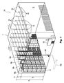
[0025] 図1および図2に示すのは、倉庫占有枠10および1つ以上の保管商品12の保護用防火システム100の好ましい実施形態である。本明細書において説明する好ましいシステムおよび方法は、倉庫占有枠の防火のために2つの原理を利用する。(i)火災の検出および位置突き止め、および(ii)火災に効果的に対処するため、そして更に好ましくは火災を鎮静化するために、火炎に対して水のような消火流体の、好ましくは一定の最小体積流量を制御して放出および配給することによって、閾値時機において火災に対して応答する。更に、好ましいシステムおよび方法は、火災に対処する、そして更に好ましくは鎮静化する好ましい手段に結合された流体配給デバイスを含む。
[0025] Shown in FIGS. 1 and 2 is a preferred embodiment of a
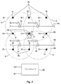
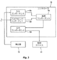
[0026] 本明細書において示し説明する好ましいシステムは、流体配給サブシステム100a、制御サブシステム100b、および検出サブシステム100cを有し、火災を鎮静化する手段を含む。図2を参照すると、流体配給および制御サブシステム100a、100bは、好ましくは、選択的に特定された流体配給デバイス110の動作を制御するために、1つ以上の制御信号CSの通信によって協働する。流体配給デバイス110は、火災に効果的に対処するため、更に好ましくは火災を鎮静化するために、検出された火災Fの現場の好ましくは実質的に上および周囲に消火流体の好ましい固定体積流量Vを送出し配給する好ましい放出アレイを形成する。固定体積流量Vは、配給される放出物(discharge)Va、Vb、Vc、およびVdの集合体によって定めることができる。検出サブシステム100cは、制御サブシステム100bと共に、直接または間接的に、(i)保管占有枠10における火災Fの場所および大きさを判定し、(ii)本明細書において説明するような好ましい態様において流体配給デバイス110を選択的に特定して動作を制御する。検出および制御サブシステム100b、100cは、好ましくは、1つ以上の検出信号DSの通信によって、火災Fを検出しその場所を突き止めるために協働する。図1に示すように、流体配給デバイスは、倉庫占有枠の天井の下、および商品の上における好ましい位置から、商品の「天井単独」防火を図るために、消火流体の分散のために配置されている。好ましくは、検出サブシステム100cは、好ましくは天井単独防火システムの支援のために、天井の下および商品の上に配置された複数の検出器130を含む。制御サブシステム100bは、好ましくは、1つ以上のコントローラ120を含み、更に好ましくは、選択的に特定されたデバイス110のグループの動作制御のために、検出器130および流体配給デバイス110に結合された集中コントローラ120を含む。
[0026] The preferred system shown and described herein has a
[0027] 検出サブシステム100cの検出器130は、占有枠を監視して、温度、熱エネルギ、スペクトル・エネルギ、煙、または占有枠における火炎の存在を示す他のパラメータの内任意の1つについて変化を検出する。検出器130は、熱電対、サーミスタ、赤外線検出器、煙検出器、およびその同等品の内任意の1つまたは組み合わせとすることができる。本システムにおいて使用できる既知の検出器には、SIMPLEX, TYCO FIRE PROTECTION PRODUCTS社のTrueAlarm(登録商標)Analog Sensingアナログ・センサが含まれる。天井単独システム100の好ましい実施形態では、図1の例について見られるように、倉庫占有枠10の監視用の1つ以上の検出器130は、好ましくは、流体配給デバイス110に近接して配置され、更に好ましくは、天井Cの下およびその近くに配置される。検出器130は、図2Aに模式的に示すように、スプリンクラ110と軸方向に整列されて装着することができ、または代わりに、図2および図2Bに模式的に示すように、配給デバイス110の上にあるのでもよく、更に配給デバイス110からずれてもよい。更に、検出器130が、天井単独保護をサポートするために商品の上に位置するのであれば、流体配給デバイス110から同じ高さまたは任意の異なる高さに配置することができる。検出器130は、本明細書において説明するような処理のために、検出データまたは信号をシステム100のコントローラ120に通信するために、コントローラ120に結合されている。火災を示す環境的変化を監視する検出器130の能力は、使用される検出器のタイプ、検出器の感度、検出器のカバレッジ・エリア、および/または検出器と火元との間の距離によって異なる可能性がある。したがって、検出器130は、個々にそして集合的に、説明する態様で占有枠10を監視して火災の状態を検出するために、しかるべく装着され、離間され、および/または配向される。
[0027] The
[0028] 検出器130および流体配給デバイス110の各々からおよび/またはへの種々の入力および出力信号を受信し、処理し、生成する、好ましい集中コントローラ120を模式的に図3に示す。機能的に、好ましいコントローラ120は、データ入力コンポーネント120a、プログラミング・コンポーネント120b、処理コンポーネント120c、および出力コンポーネント120dを含む。データ入力コンポーネント120aは、 例えば、連続または間欠温度データ、スペクトル・エネルギ・データ、煙データ、またはこのようなパラメータを表す生の電気データというような、例えば、生の検出データまたは較正したデータを含む、検出データまたは信号の内任意のもの、例えば、占有枠の測定された環境パラメータを示す電圧、電流、またはディジタル信号を検出器130から受信する。検出器130から収集される追加のデータ・パラメータには、検出器の時間データ、アドレス、または位置データを含むことができる。好ましいプログラミング・コンポーネント120bは、火災の検出、火災の場所、火災のプロファイル、火災の大きさ、および/または火災成長の閾値時機を定めることができる、ユーザ定義パラメータ、判断基準、または規則の入力を可能にする。更に、プログラミング・コンポーネント120bは、検出された火災に応答して、動作させる流体配給デバイスまたはアセンブリ110を特定するための選択パラメータまたはユーザ定義パラメータ、判断基準、あるいは規則の入力を可能にする。パラメータ、判断基準、あるいは規則は、以下の内1つ以上を含む。分散デバイス110間の関係、例えば、近接度、隣接性(adjacency)等を定める。動作させるデバイスの数、即ち、最大値および最小値の限度、動作時間、動作のシーケンス、動作のためのデバイスのパターンおよびジオメトリ(geometry)、これらの放出速度を定める。および/または検出器130に対する関連または関係を定める。本明細書において説明する好ましい制御方法において示されるように、検出器130を流体配給デバイス110と1対1に基づいて関連付けることができ、または代わりに1つよりも多い流体配給デバイスと関連付けることができる。加えて、入力および/またはプログラミング・コンポーネント120a、120bは、本明細書において説明するように分散デバイスの方法を実行するために、流体配給デバイス110とコントローラ120との間におけるフィードバックまたはアドレシングを可能にする。
[0028] A preferred
[0029] したがって、好ましい処理コントローラ120cは、火災を検出し場所を突き止め、流体配給デバイスを選択し、流体配給デバイスに優先順位を付け、および/または流体配給デバイスを特定し好ましい態様で動作を制御するためにするために、入力およびプログラミング・コンポーネント120a、120bからの入力およびパラメータを処理する。例えば、好ましい処理コントローラ120cは、概略的に、閾値時機に達したときを判定し、コントローラ120の出力コンポーネント120dと共に、好ましくは、1つ以上の本明細書において説明する方法にしたがって、特定された、そして好ましくはアドレス可能な配給デバイス110の動作を制御するために、しかるべき信号を生成する。システム100において使用可能な既知のコントローラの一例に、TYCO FIRE PROTECTION PRODUCTS社のSimplex(登録商標)4100 Fire Control Panelがある。プログラミングは、ハードワイヤされても、または論理的にプログラミングされもよく、システム・コンポーネント間の信号は、アナログ、ディジタル、または光ファイバ・データの内1つ以上とすることができる。更に、システム100のコンポーネント間の通信は、有線またはワイヤレス通信の内任意の1つ以上とすることができる。
[0029] Accordingly, the preferred process controller 120c detects and locates fires, selects fluid delivery devices, prioritizes fluid delivery devices, and / or identifies fluid delivery devices and controls operations in a preferred manner. In order to do so, it processes the inputs and parameters from the input and
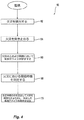
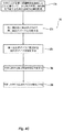
[0030] 図4に示すのは、システム100におけるコントローラ120の動作160を一般化した好ましい実施形態である。このシステムの動作状態では、処理コンポーネント120cは火災Fを検出し(162)場所を突き止める(164)ために入力データを処理する。本明細書における好ましい方法によれば、処理コンポーネント120cは、検出サブシステム100cからの検出および/またはその他の入力データまたは信号に基づいて、突き止められた火災Fの上および周囲に好ましいアレイを形成する流体配給デバイス110を特定し、その放出を制御する(166)。処理コンポーネント120cは、好ましくは、選択された流体配給デバイスのアレイの動作および放出のために、火災における閾値時機を判定する(168)。ステップ170において、処理コンポーネント120cは、出力コンポーネント120dと共に、特定した流体配給デバイスを動作させて火災に対処するため、更に好ましくは火災を鎮静化するために(170)、しかるべく通知する。
FIG. 4 illustrates a preferred embodiment that generalizes the operation 160 of the
[0031] 放出アレイは、好ましくは初期に、選択および優先された数の流体配給デバイス110、ならびに好ましくは検出された火災の上を中心に位置付けられた外形によって定められる。本明細書において説明するように、放出アレイにおける放出デバイス110の数は、予めプログラミングすることまたはユーザが定めることができ、更に好ましくは、アレイを形成するデバイスの最大数を予めプログラミングしまたはユーザが定め、この最大数までに制限される。更に、選択数またはユーザが定めた数の放出デバイスは、例えば、システム100の配給デバイス110のタイプ、間隔および水力要件を含むその設置構成(installation configuration)、検出器130のタイプおよび/または感度、保護対象商品の危険のタイプまたはカテゴリ、倉庫の構造(arrangement)、倉庫の高さ、および/または倉庫占有枠の天井の最大高さというような、システム100の1つ以上の係数および/または保護対象商品に基づくことができる。例えば、配給デバイスの直線格子の下に保管されたグループA露出発泡プラスチックのように、危険性が高い商品では、放出アレイを形成する流体配給デバイスの好ましい数は、好ましくは8(8つのデバイスによる3×3正方形周囲)とすることができ、また更に好ましくは9(デバイスの3×3格子アレイ)とすることができる。他の例では、グループA箱詰め非発泡プラスチックでは、図2に模式的に示すように、放出デバイスの好ましい数は4(デバイスの4×4格子アレイ)とすることができる。あるいは、危険性が低い商品では、アレイの放出デバイスの数は、1つ、2つ、または3つとすることができ、実質的に火災Fの上に中心がありその周囲に位置付けられる。この場合も、放出アレイにおけるデバイスの特定化された数(particularized number of devices)は、システムの種々の係数および保護対象商品に応じて定めることができる。好ましくは、結果的に得られた放出アレイが、効果的に火災に対処し、更に好ましくは火災を鎮静化するために、好ましくは、検出された火災Fの現場の実質的に上および周囲に、固定体積流量Vの消火流体を送出して配給する。
[0031] The discharge array is preferably initially defined by a selected and prioritized number of
[0032] 放出アレイ用の流体配給デバイス110の特定および/またはアレイの形状は、動的に決定することができ、または代わりに統一的決定でもよい。本明細書において使用する場合、「動的な決定」とは、放出アレイを形成するための特定の配給デバイス110の選択および特定が、好ましくは、ある時間期間にわたって、火災の最初の検出が確定した(define)時点から、火災における閾値時機が定められるまでの検出器読み取り値の関数として決定されることを意味する。対照的に、「統一的」決定では、放出アレイの配給デバイスの数、およびそのジェオメトリが予め決められており、アレイの中心または位置が、好ましくは、特定のレベルの検出または他の閾値時機の後に決定される。放出アレイの特定および動作のための以下の好ましいコントローラ動作によって、動的決定および統一的決定を実証する。
[0032] The identification of the
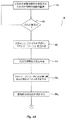
[0033] 図4Aおよび図4Bに示すのは、システム100のコントローラ120の他の好ましい動作実施形態例200のフローチャートである。最初のステップ200aにおいて、コントローラ120は検出器130からの検知出力または検出出力に基づいて、占有枠の環境を連続的に監視する。ステップ200bにおいて、コントローラ120は、データを処理して火災Fの存在を判定する。火災の指示は、例えば、急激な温度上昇、スペクトル・エネルギの急激な上昇、または他の測定パラメータの急激な上昇というような、検出器130からの検知データにおける急激な変化に基づくことができる。コントローラ120が火災の存在を判定した場合、コントローラ120はステップ200cにおいてこの火災のプロファイルを作成し(develop)、更に好ましくは、着信する検出データに基づいて成長の「ホット・ゾーン」即ち火災成長エリアを定める。好ましいプロファイルまたは「ホット・ゾーン」を確定すると、コントローラ120は次にステップ200dにおいて火災の火元即ち現場を突き止める。1つの特定的な実施形態では、好ましいコントローラ120はステップ200d1において火災プロファイル即ち「ホット・ゾーン」内にある全ての検出器130および配給デバイス110を判定する。次のステップ200d2において、コントローラ120は、火災に最も近い検出器130または配給デバイス110を判定する。1つの好ましい態様では、この判定は、ホット・ゾーンにおいて最も高い測定値を測定した検出器130の識別に基づくことができる。好ましくは、コントローラ120は、ステップ200eにおいて、最高値の検出器130に対する流体配給デバイス110の近接度を判定することができる。
[0033] Shown in FIGS. 4A and 4B are flowcharts of another example
[0034] 更に好ましくは、コントローラ120は、好ましい放出アレイを形成するために、火災の上、周囲、そして更に好ましくは最も近い流体配給デバイス110を特定する。例えば、コントローラ120は、好ましくは動的にそして繰り返し、ステップ200fにおいて、最も高い測定値の検出デバイス、または他の選択判断基準の検出デバイスの周囲上において、最も近い4つの放出デバイス110を特定する。あるいは、コントローラ120は、選択判断基準に基づいて、例えば、8つまたは9つの配給デバイスというような、任意の他の好ましくはユーザが定めた数の配給デバイス110を選択し特定することができる。次いで、ステップ200gにおいて、火災の周囲および上において動作させる最も近い4つの配給デバイス110を特定する。ステップ200hにおいて、コントローラ120は、好ましくは、火災の上および周囲においてこれら4つの配給デバイス110を動作させる閾値時機を決定する。コントローラ120には、好ましくは、ユーザが定めた閾値、温度に関する時機(moment)または判断基準、熱放出率、温度上昇率、または他の検出パラメータをプログラミングすることができる。閾値時機は、システム・パラメータの任意の1つまたは組み合わせから決定することができ、例えば、ユーザが定めた閾値よりも高いデータ読み取り値を有する検出器の数、「ホット・ゾーン」内においてユーザが定めた量に達した流体配給デバイスの数、閾値レベルに達した温度プロファイル、ユーザが指定した時間に対する傾斜に達した温度プロファイル、ユーザが定めた閾値レベルに達したスペクトル・エネルギ、および/またはユーザが定めた特定レベルに達した煙検出器から決定することができる。一旦閾値時機に達したなら、コントローラ120はステップ200iにおいて、4つの配給デバイス110に動作について通知する。更に好ましくは、コントローラ120は、火災に対処するため、そして更に好ましくは火災を鎮静化するために、放出アレイの選択された4つの配給デバイス110を実質的に同時に動作させる。
[0034] More preferably, the
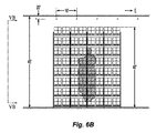
[0035] 図5Aに示すのは、ラック配列で保管された商品の上に配置された、好ましい天井単独システム100の平面図である。特に、流体配給デバイス110a〜100pおよび検出器130a〜103pの格子例を示す。方法200の一例では、検出器130が火災を検出し、プロセッサ120は火災Fの場所を判定する。例えば、検出器130gが最も高い読み取り値の検出器として特定された場合、流体配給デバイス110f、110g、110j、11kがコントローラ120によって、「ホット・ゾーン」において火災の上および周囲にあると特定される。コントローラ120は、「ホット・ゾーン」内においてユーザが定めた閾値に一致するまたはこれを超過する検出器に基づいて火災に対処するために、流体配給デバイス110f、110g、110j、110kを動作させる。
[0035] Shown in FIG. 5A is a plan view of a preferred ceiling-only
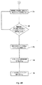
[0036] 図4Cに示すのは、システム100のコントローラの他の好ましい動作実施形態例300を示すフローチャートである。最初のステップ300aにおいて、コントローラ120は、占有枠の環境を監視して、火災において第1閾値時機と一致するまたはこれを超過する値を読み取った検出器130からの検知または検出入力に基づいて、火災の指示、そして好ましくはその場所を求める。例えば、1つ以上の検出器130が、温度上昇率閾値、閾値温度、または他の測定パラメータと一致するまたはこれを超過する読み取り値を戻す可能性がある。コントローラ120はデータを処理して、好ましくは、ステップ300bから、1つ以上の検出器130に最も近いまたはこれと関連付けられた第1配給デバイス110、そして更に好ましくは、判定された火災の場所に最も近い第1配給デバイス110を判定する。コントローラ120は、ステップ300cにおいて、以前に特定された第1配給デバイス110に好ましくは直接隣接する配給デバイス、そして更に好ましくは第1配給デバイス110を包囲する配給デバイスを特定することによって、検出された火災に対処するために好ましい放出アレイを特定する。隣接する配給デバイスの特定は、好ましくは、コントローラ120のプログラミングに基づき、このプログラミングは、デバイス間で識別された隣接性または相対的位置付けに関係付けることができる各デバイスのアドレスまたは位置を与える。更に、好ましいアレイにおけるデバイスの数は、ユーザが定めた数、または予めプログラミングされた数とすることもできる。次いで、コントローラ120は、ステップ300dにおいて、好ましくは、ステップ300aの最初の検出の判定において使用したのと同じパラメータまたは判断基準を使用して、あるいは好ましくはそれよりも高い閾値を使用して、火災における第2閾値時機を決定する。第2閾値は、1つ以上の検出器130から戻される読み取り値によって定めることができる。第2閾値時機が検出されると、次に、コントローラ120は、好ましいステップ300eにおいて、検出した火災に対処するために、好ましいアレイの特定されたデバイス110全てを動作させる。
FIG. 4C is a flowchart illustrating another preferred example
[0037] 再度図5を参照すると、例えば、検出器130kおよび関連する配給デバイス110kが本方法の下で第1閾値において最初に特定された場合、直接隣接し包囲する8つの配給デバイス110f、110g、110h、110j、110l、110n、110o、および110pを、好ましい放出アレイの選択のために、自動的に特定することができる。例えば第1検出器130kによって、好ましくは第1よりも高い第2閾値において検出された、火災における第2閾値時機の決定に続いて、検出された火災に対処するためそして好ましくは火災を鎮静化する放出のために、好ましいアレイをコントローラによって動作させることができる。あるいは、第2閾値時機は、例えば、第1検出器130kと同じまたはそれより高い閾値において読み取る第2検出器130gによって検出することもできる。このような好ましい実施形態では、隣接および包囲するデバイスの特定は、好ましくは、温度検出または他の測定熱パラメータとは独立しており、代わりに、予め設定された場所、あるいは隣接性または相対的位置付けを判定するため予めプログラミングされたデバイスのアドレスに基づく。
[0037] Referring again to FIG. 5, for example, if the detector 130k and associated delivery device 110k were first identified at the first threshold under the method, eight immediately adjacent and surrounding
[0038] 代わりにまたは加えて、ユーザが定めたパラメータが、例えば、4つの配給デバイスというように、好ましい放出アレイにおいてもっと少ない数の配給デバイス110を指定する場合、好ましい配給アレイをどのように突き止め中心を決めるか判断するために、第2検出器130の識別情報(identification)を使用することができる。再度図5Aを参照すると、検出器130kおよび関連する配給デバイス110kが第1閾値の下で最初に特定された場合、直接隣接するおよび包囲する8つの配給デバイス110f、110g、110h、110j、110l、110n、110o、および110pを、好ましい放水アレイの可能な選択のために特定することができる。ユーザが定めたまたは予めプログラミングされた第2の閾値において、検出器130fが特定された場合、コントローラは4つの流体配給デバイス110f、110g、110j、および110kを、好ましい4−デバイス放出アレイとして固定的に特定して動作を制御することができる。したがって、1つの態様では、この方法は、第1配給デバイスを特定する熱検出のときに、配給デバイス110のグループまたはゾーンの、好ましいユーザが定めた作動、予め設定された作動、一定の作動、または予めプログラミングされた作動を実行する(provide for)ことができる。
[0038] Alternatively or additionally, how to locate a preferred delivery array if a user defined parameter specifies a smaller number of
[0039] 図4Dに示すのは、システム100において使用する他の方法の代替実施形態である。本方法のこの実施形態は、各検出器130における火災の監視および検出に基づいて、出火地点の上および周囲、更に好ましくは、出火地点を中心に配されここを包囲する流体配給デバイス110のアレイを動的に特定し動作させる。各検出器130は、好ましくは、1つの放出デバイス110と関連付けられる。本方法は、2つの異なる検出器感度閾値を採用し、一方が他方よりも感度が高い、または閾値が低い。低い方の閾値は、検出された火災の上および周囲における好ましい数の配給デバイスを特定し動作を制御するために、好ましい予備警報閾値を定める。低い方の感度または高い方の閾値は、流体配給デバイスの識別されたグループの作動の時機(moment)を特定する。
[0039] Shown in FIG. 4D is an alternative embodiment of another method used in
[0040] 本システムおよび方法のこの実施形態では、コントローラ120は、好ましい予備警報閾値および好ましい上位警報閾値を定めるようにプログラミングされる。これらの閾値は、上昇率、温度、または検出器130の任意の他の検出パラメータの1つ以上の組み合わせとすることができる。更に好ましくは、コントローラ120には、好ましい放出アレイに特定される配給デバイスの最小数がプログラミングされる。好ましくは、予備警報閾値と一致したまたはこれを超過した検出器に関連する配給デバイスで構成されたデバイス・キューが定められる。プログラミングされた最小数のデバイス110は、プログラミングされた警報閾値においてコントローラ120によってアレイが作動または動作させられる前に、キュー内にあることが必要な最小数のデバイスを定める。更に好ましくは、コントローラ120によって動作させるデバイスの数を制限するために、デバイス・キューにおける配給デバイス110の最大数がコントローラ120にプログラミングされる。
[0040] In this embodiment of the system and method, the
[0041] 45フィート(45ft)の天井の下に40フィート(40ft)まで露出発泡プラスチックを保管する二重列ラックの保護のためにプログラミングされたコントローラ120の実施形態例では、警報閾値を135°F、そしてデバイスの最小数および最大数をそれぞれ4および6とした場合、予備警報閾値を毎分20°Fの上昇率に設定することができる。図4Dに示す方法400の実施形態例では、ステップ402において、コントローラ120は温度情報を検出器130から受信する。ステップ404において、コントローラ120はこれらの検出器130の各々からの履歴温度情報、および検出器130の各々によって検出された現在の温度を確認し、これらの検出器の各々における温度上昇率を判定する。ステップ406において、いずれかの検出器130の上昇率が、予備警報上昇率閾値よりも高いか否か判定を行う。検出器が予備警報閾値と一致したまたはこれを超過したと判定した場合、ステップ408において、この検出器130に関連する配給デバイス110がデバイス・キューに入れられる。ステップ410において、検出器130は、警報閾値以上の上昇率を検出するために、占有枠を監視し続ける。警報閾値と一致したまたはこれを超過し、更にデバイス・キューにおける配給デバイス110の数が、デバイスの最小数以上で、デバイス・キューにおける配給デバイスの最大数未満である場合、ステップ412においてキュー内にあるデバイスに動作を通知する。この場合も、コントローラ120のプログラムにおいて特定された最大数まで、コントローラ120はデバイス動作の総数を制限または制御することができる。
[0041] In an example embodiment of
[0042] 図5Aおよび火災事象例Fを参照すると、検出器130は倉庫占有枠を監視する。例えば、8つの検出器130が、プログラミングされた予備警報閾値を超過する温度および/または上昇率を検出した場合、デバイスのキューが順次最大数の6つまで配給デバイス110が積み上げられ、各デバイスには8つの検出器130の内1つが関連付けられる。このキューにおける配給デバイス110は、例えば、110b、110c、110f、110g、110j、110kを含むことができる。一旦警報閾値に等しくなったかまたは超過した場合、デバイス・キューを形成する6つのデバイスを動作させ、更に好ましくは、火災Fに対処するために同時に動作させることができる。
[0042] Referring to FIG. 5A and example fire event F,
[0043] 加えてまたは任意に、コントローラ120にはバックアップ閾値をプログラミングすることができる。バックアップ閾値は検出または導出されるパラメータであり、予備警報および警報閾値と同じであることまたは異なることができ、デバイス・キューが作動された後に、動作制御のために追加のデバイスを作動させる条件または時機を定める。既に説明した保護システムに対するバックアップ閾値例は、175°Fとすることができる。加えて、コントローラには、合計9つのデバイスの初期デバイス・キューの動作後に動作させる、例えば、3つのデバイスというような、追加の配給デバイス110の好ましい最大数をプログラミングすることができる。任意に動作400の方法の図4Dに示され、配給デバイス110のキューの動作の後に、検出器130が直接または間接的にバックアップ閾値に等しい値またはこれを超過する値を検出した場合、それぞれステップ414、416において、最大数の追加までの追加のデバイスを特定し動作させ、その動作を制御することができる。したがって、デバイス・キューを定めるための6つの最大配給デバイス、および3つの最大追加デバイスがプログラムにプログラミングされた場合、検出器130がバックアップ閾値以上の火災パラメータを検出し続けるとき、合計8つのデバイスをコントローラ120によって動作させることができる。例えば、デバイス110a、110e、110iの関連する検出器130がバックアップ閾値と一致したまたはこれを超過した場合、これらを作動させる。
[0043] Additionally or optionally, the
[0044] 図4Eに示すのは、システム100におけるコントローラ120の動作の方法500の他の実施形態である。本方法のこの実施形態では、火災の状態を継続的に監視し、必要に応じて、好ましくは火災に対処し放水の体積を最小限に抑える、所望の固定グループの流体配給デバイスによって、火災に対処する。方法500の流体配給デバイスの動作は、コントローラ120によって制御することができ、更に好ましくは、流体配給デバイスは、好ましくは、流体制御に合わせて構成され、コントローラ120が放水を中止および再開することができ、更に好ましくは、流体配給デバイス110からの流量を制御することができる。
FIG. 4E illustrates another embodiment of a method 500 of operation of the
[0045] 好ましい第1ステップ501において、例えば、閾値温度、上昇率、または他の検出パラメータのような、プログラミングされた警報閾値条件に等しいまたはこれを超過する検出読み取り値に応答して、好ましくは、コントローラ120によって第1検出器130を特定する。ステップ502において、好ましくは、特定された第1検出器130に対するプログラミングされた関連付けまたはプログラミングされた近接度に基づいて、1つ以上の流体配給デバイス110を動作させる。検出器130を流体配給デバイスと1対1で関連付けることができ、また代わりに、例えば、1つの検出器130を包囲しこれを中心に配された4つの配給デバイス110のグループというような、1つよりも多い流体配給デバイスを関連付けることもできる。図4Eおよび図5Aを参照すると、本方法およびステップ502の好ましい一実施形態では、制御される流体配給デバイスは、好ましくは、特定された第1検出器130gと関連付けられた1つの主配給デバイス110g、および主配給デバイス110gを中心に配された8つの副配給デバイス110b、110c、110d、110f、110h、110j、110k、110lの組み合わせを含む。ステップ502において、主および副デバイス110は、例えば、2分というような動作期間、第1放出パターンを定めるように起動させられる(activate)。
[0045] In a preferred
[0046] 第1放水パターン期間に続いて、ステップ504において、火災が抑制されたか、制御されたか、またはそれ以外で効果的に対処されたか否か判定を行う。本システムの検出器130およびコントローラ120は、この判定を行うために、占有枠を監視し続ける。火災が効果的に対処された、更に好ましくは鎮静化されたと判定した場合、流体配給デバイス110の全ての動作を停止させ、方法500を終了する。しかしながら、火災が効果的に対処されていないと判定した場合、同じ第1放水パターンで流体配給デバイス110を再度起動させ、または更に好ましくは、ステップ506において、異なる第2放水パターンが、消火流体を用いて火災を標的にし続ける。第2パターンを定める流体配給デバイス110は、プログラミングされた期間、例えば、30秒(30sec)の間、コントローラ120によって解放したままに維持される。火災に対処するために使用される水の総量は、好ましくは最小限に抑える。したがって、好ましい一実施形態では、第2放水パターンは、好ましくは、主配給デバイス110gを中心に配された4つの副配給デバイス110c、110f、110h、110kによって定められる。加えてまたは代わりに、第2放水パターンは、好ましい最小流体流量を得るために、1つ以上の配給デバイス110からの消火流体の流量、または放水期間を変更することにより、第1放水パターンとは異なるものにすることができる。
[0046] Following the first water discharge pattern period, in
[0047] 好ましいステップ508において、コントローラは、好ましくは、第3放水パターンを定めるために、主配給デバイスを中心とする副配給デバイス110を再度変更する。例えば、第3放水パターンを定めるために、副配給デバイス110b、110d、110j、110lを動作させる。第3パターンは、30秒(30sec)または他のプログラミングされた放水期間にわたる放水である。第2および第3放水パターンの好ましい順次起動により、水の使用を最小に抑え、したがって他のものに対する潜在的な水による損傷を最小に抑えつつ、好ましくは火災の上および周囲における流体配給デバイスの周囲境界(perimeter)の形成および維持を容易にする。ステップ506および508に続いて、ステップ510において、火災が効果的に対処されているか再度判定する。火災が効果的に対処されており、更に好ましくは鎮静化された場合、ステップ505において配給デバイスの全ての動作を停止する。しかしながら、火災が効果的に対処されていないと判定した場合、コントローラはステップ506から508までを繰り返して、既に説明した順次第2および第3パターンで消火流体を放出し続ける。
[0047] In a
[0048] 好ましい天井単独防火システムでは、火災に効果的に対処し、更に特定すれば鎮静化する能力は、倉庫占有枠、および保護対象保管商品の構成(configuration)によって左右される可能性がある。システムの設置および性能に影響を及ぼす占有枠および保管商品のパラメータには、倉庫占有枠10の天井高さHI、商品12の高さ、商品12の分類、ならびに保護しようとする商品12の保管配置および高さを含むことができる。したがって、天井単独システムにおける好ましい鎮火手段は、好ましい放水アレイを形成する好ましい数およびパターンの流体配給デバイスを動作させるために、火災を検出し位置を突き止めることができ、露出発泡グループAプラスチックまでを含む、危険が最大である商品分類の商品の最高天井および保管高さにおいて、火災に対処し更に好ましくは鎮静化することができる。
[0048] In a preferred ceiling-only fire protection system, the ability to effectively deal with fire, and more particularly to subside, can depend on the warehouse occupancy and the configuration of the protected goods to be protected. . The parameters of the occupancy frame and the stored product that affect the installation and performance of the system include the ceiling height HI of the warehouse occupancy frame 10, the height of the
[0049] 図1を参照すると、占有枠10の天井Cは、平坦天井、水平天井、傾斜天井、またはこれらの組み合わせの内任意の1つを含む任意の構成にすることができる。天井高さHIは、好ましくは、倉庫占有枠10の床と、保護対象保管エリア内上部の天井C(またはルーフ・デッキ)の下側との間の距離によって定義され、更に好ましくは、床と上部天井C(またはルーフ・デッキ)の下側との間の最大高さを定義する。商品アレイ12は、NFPA−13の第3.9.1章において規定され定義されているパラメータの内1つ以上によって特徴付けることができる。アレイ12は、倉庫高さH2まで格納することができ、倉庫高さH2は、好ましくは、倉庫の最大高さ、および天井と最も高い保管商品の上面との間の公称天井−保管物隙間CLを定義する。天井高さHIは、20フィート以上にすることができ、そして30フィート以上、例えば、公称45フィート(45ft)まで、あるいは、例えば、公称50フィート(50ft)、55(55ft)、60フィート(60ft)、またはそれよりも高く、具体的には65フィート(65ft)までといように、更に高くすることもできる。したがって、倉庫高さH2は12フィート以上にすることができ、公称上20フィート以上、例えば、公称25フィート(25ft)から公称60フィート以上まで、好ましくは公称上20フィートと60フィートとの間の範囲を取ることができる。例えば、倉庫高さは、45フィート(45ft)、50フィート(50ft)、55(55ft)、または60フィート(60ft)の最大公称倉庫高さH2までとすることができる。加えてまたは代わり、倉庫高さH2は、好ましくは、1フィート、2フィート、3フィート、4フィート、または5フィート、あるいはこれらの間の任意の数値の内任意の1つの最小公称天井−保管隙間CLを定めるように、天井Cの下で最大にすることもできる。
[0049] Referring to FIG. 1, the ceiling C of the occupying frame 10 may have any configuration including any one of a flat ceiling, a horizontal ceiling, an inclined ceiling, or a combination thereof. The ceiling height HI is preferably defined by the distance between the floor of the warehouse occupancy frame 10 and the lower side of the ceiling C (or roof deck) in the upper part of the protected storage area, more preferably the floor Defines the maximum height between the upper ceiling C (or roof deck) and the underside. The
[0050] 保管された商品のアレイ12は、好ましくは、例えば、一列ラック配置、好ましくは、多重列ラック保管配置、そして更に一層好ましくは二重列ラック保管配置というような、高積層保管(12フィート(12ft)を超える)ラック配置を定める。他の高積層保管構成もシステム100によって保護することができ、例えば、パレタイズド(palletized)、棒積み(solid-piled)(積み上げられた商品)、ビン・ボックス(五面箱における保管、箱の間には空間が殆どまたは全くない)、棚(少なくとも30インチ幅の通路によって分離された、奥行き30インチまでの構造体における保管)、または背中合わせ棚保管(垂直バリアによって分離され、長手方向煙道空間がなく、最大保管高さが15フィートである2つの棚)を含む非ラック保管配置(non-rack storage arrangement)を含む。また、保管エリアは、同じまたは異なる構成で通路幅Wだけ離間された同じまたは異なる商品の追加保管も含むことができる。更に好ましくは、アレイ12は主アレイ12a、および1つ以上の目標アレイ12b、12cを含むことができ、図5Aおよび図5Bにおいて見られるように、各々主アレイに対して通路幅W1、W2を定める。
[0050] The array of stored
[0051] 保管された商品12は、NFPA−13によって定義されたクラスI、II、III、またはIV商品、あるいはグループA、グループB、またはグループCプラスチック、エラストマ、およびラバーの内任意のもの、あるいは更にその代わりに燃焼挙動を特徴付けることができる任意のタイプの商品を含むことができる。グループAプラスチックの保護に関して、本システムおよび方法の好ましい実施形態は、発泡および露出プラスチックの保護に合わせて構成することができる。NFPA13、第3.9.1.13章によれば、「発泡(海綿状(foamed or cellular))プラスチック」とは、「質量全体に分散され、相互接続するまたはしない、多数の小さなキャビティ(セル)の存在によって密度が低下したプラスチック」と定義されている。NFPA13の第3,9,1,14章では、「露出グループAプラスチック商品」を「水を吸収するまたは燃焼の危険性を明らかに遅らせる包装や被覆がなされていないプラスチック」と定義する。
[0051] The stored
[0052] 本明細書において説明したようなやり方で保管商品における火災に応答することにより、更に特定すれば鎮静化することにより、好ましいシステム100は、保管商品に対する火災の影響を著しく限定する、そして更に好ましくは影響を低減するレベルの防火性能を図る。これは、例えば、抑制または火災制御というような、既に知られている防火活動(performance)と比較して、保管された商品に対する損傷を低減すると考えられる。更に、露出発泡プラスチック商品の保護では、好ましいシステムおよび方法は、現在の設置規格の下では利用できない高さおよび配置においても天井単独保護を可能にする。加えてまたは代わりに、好ましいシステムおよび方法は、例えば、垂直または水平バリアというような設備がなくても、露出発泡プラスチック商品の天井単独保護を可能にする。本明細書において説明したように、実際の火災検査を実行して、本明細書において説明した好ましいシステムおよび方法の好ましい鎮火性能を実証することができる。
[0052] By responding to fires in stored goods in the manner described herein, and more particularly by calming down, the
[0053] 好ましいシステム100の好ましい天井単独配置では、図1、図5A、および図5Bに模式的に示すように、流体配給デバイス110は天井Cと保管商品によって定められる平面との間に設置される。流体配給サブシステム100aは、占有枠の天井の下、および保護すべき商品の上に吊された部分を有する導管網150を含む。システム100の好ましい実施形態では、天井単独保護を可能にするために、複数の流体配給デバイス110が導管網150に装着または接続される。好ましくは、導管網150は、1本以上の主導管150aを含み、ここから1本以上の分岐導管150b、150c、150dが出て行く。配給デバイス110は、好ましくは、所望のデバイス同士間隔a×bを形成するために、離間された分岐導管150b、150c、150dに装着され、これらに沿って離間される。検出器130は、好ましくは各配給デバイス110の上に配置され、更に好ましくは各配給デバイス110と軸方向に整列される。配給デバイス110、分岐ライン、および主導管(1本または複数)は、格子状導管網または樹木状導管網のいずれかを形成するように編成することができる。更に、導管網は、システム100の流体配給部分および流体配給デバイス110に相互接続するために、コネクタ、エルボー、およびライザ等というような導管継ぎ手も含むことができる。
[0053] In a preferred ceiling alone arrangement of the
[0054] 導管網150は、例えば、給水本管150eまたは給水タンクのような、消火流体の供給元に、流体配給デバイス110を接続する。流体配給サブシステムは、更に、例えば、所望の流速および/または圧力で水を配給デバイス110に送出するために、消火ポンプまたは逆流防止器というような、追加のデバイス(図示せず)も含むことができる。更に好ましくは、流体配給サブシステムは、好ましくは流体供給元150eから導管本管150aまで延びるライザ管150fも含む。ライザ150fは、水配給サブシステム110aを通過する流体流を誘導、検出、測定、または制御するために追加のコンポーネントまたはアセンブリを含むことができる。例えば、本システムは、スプリンクラから逆に流体源に向かう流体流を防止するために、チェック・バルブを含むことができる。また、本システムは、ライザ150fおよびシステム100を通る流量を測定するために流量計を含むこともできる。更に、流体配給サブシステムおよびライザ150fは、例えば、差動流型(differential fluid-type)流体制御バルブのような、流体制御バルブを含むことができる。システム100の流体配給サブシステム100aは、好ましくは、ウェット・パイプ・システム(wet pipe system)(デバイス動作時に流体が直ちに放出する)またはその変形として構成され、即ち、非連動、単一連動、または二重連動プリアクション・システム(double-interlock preaction system)(システム配管には初期状態において気体が充填されており、次いで流体がデバイス動作時に配給デバイスからその動作圧力で放出するように、検出サブシステムからのシグナリングに応答して消火流体が充填される)を含む。
[0054] The
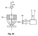
[0055] 流体配給デバイス110の好ましい実施形態は、図2Aおよび図2Bに模式的に示すように、フレーム・ボディに結合された流体偏向部材を含む。フレーム・ボディは、配管網への接続のための入口と、出口とを含み、これらの入口および出口の間に内部通路が延びている。偏向部材は、好ましくは、固定離間関係で、出口から軸方向に離間される。入口に送出される水または他の消火流体は、偏向部材に衝突する(impact)ために、出口から放出される。偏向部材は、火災に対処するため、そして更に好ましくは鎮静化するために好ましい集合的体積流量に寄与する体積流量を送出するために、消火流体を配給する。あるいは、偏向部材は、動作時に所望の態様で消火流体を配給するのであれば、出口に関して平行移動することができる。本明細書において説明する天井単独システムでは、図5Bに模式的に示すように、流体配給デバイス110の偏向部材が好ましくは天井から所望の偏向部材−天井間距離Sのところに位置付けられるように、流体配給デバイス110を設置することができる。あるいは、天井単独構成において保護対象商品上にデバイス110が位置付けられるのであれば、デバイス110を天井Cから任意の距離に設置することもできる。
[0055] A preferred embodiment of the
[0056] したがって、流体配給デバイス110は、当技術において理解されるような「防火スプリンクラ」のフレーム・ボディおよび偏向部材によって構造的に具現化することができ、そして本明細書において説明したような、作動の制御を可能にするために、しかるべく構成または変更することができる。この構成は、既知の防火スプリンクラのフレームおよびディフレクタを、本明細書において説明した変更を加えて、含むことができる。好ましいシステムおよび方法において使用するスプリンクラ・フレームおよびディフレクタ・コンポーネントは、例えば、標準的な噴霧、抑制、または拡大到達範囲、およびその等価物というような、指定されたスプリンクラ性能に対して容認可能であると業界で容認された組織によって検査および認定された既知のスプリンクラのコンポーネントを含むことができる。例えば、システム100における設置に好ましい流体配給デバイス110は、技術データ・シート「TFP312]において示され記載されているフレーム・ボディおよび偏向部材:公称25.2K−ファクタを有し、電気制御動作可能に構成された、TYCO FIRE PRODUCTS, LPからのモデルESFR−25早期抑制、高速応答、垂下スプリンクラ25.2K−ファクタ」(2012年11月)を含む。
[0056] Accordingly, the
[0057] 本明細書において使用する場合、K−ファクタとは、スプリンクラ放出係数を表す定数と定義し、スプリンクラの出口からの1分毎のガロンを単位とした流体の流量を、平方インチ毎のポンド(PSI)を単位とするスプリンクラ通路の入口に供給される流体の流量の圧力の二乗根で除算することによって定量化される。K−ファクタはGPM/(PSI)1/2で表現される。NFPA13は、スプリンクラの定格または公称K−ファクタあるいは定格放出係数を、K−ファクタ範囲にわたる平均値として規定する。例えば、K−ファクタが14以上である場合、NFPA13は、以下の公称K−ファクタを規定する(K−ファクタ範囲を括弧内に示す)。(i)14.0(13.5〜14.5)GPM/(PSI)1/2、(ii)16,8(16.0〜17.6)GPM/(PSI)1/2、(iii)19.6(18.6〜20.6)GPM/(PSI)1/2、(iv)22.4(21.3〜23.5)GPM/(PSI)1/2、(v)25.2(23.9〜26.5)GPM/(PSI)1/2、および(vi)28.0(26.6〜29.4)GPM/(PSI)1/2、あるいは約(31.8〜34.8GPM/(PSI)1/2)の範囲に及ぶ33.6GPM/(PSI)1/2の公称K−ファクタ。流体配給デバイス110の代替実施形態は、前述の公称K−ファクタまたはそれ以上を有するスプリンクラを含むことができる。
[0057] As used herein, K-factor is defined as a constant representing the sprinkler emission coefficient, and the fluid flow rate in gallons per minute from the sprinkler outlet is expressed in square inches. It is quantified by dividing by the square root of the pressure of the fluid flow rate supplied to the inlet of the sprinkler passage in pounds (PSI). The K-factor is expressed as GPM / (PSI) 1/2 . The NFPA 13 defines the rated or nominal K-factor or rated emission factor of the sprinkler as an average value over the K-factor range. For example, if the K-factor is 14 or greater, NFPA 13 defines the following nominal K-factor (K-factor range is shown in parentheses): (I) 14.0 (13.5 to 14.5) GPM / (PSI) 1/2 , (ii) 16, 8 (16.0 to 17.6) GPM / (PSI) 1/2 , (iii) ) 19.6 (18.6-20.6) GPM / (PSI) 1/2 , (iv) 22.4 (21.3-23.5) GPM / (PSI) 1/2 , (v) 25 .2 (23.9-26.5) GPM / (PSI) 1/2 , and (vi) 28.0 (26.6-29.4) GPM / (PSI) 1/2 , or about (31. 8~34.8GPM / (PSI) 1/2) 33.6GPM / (PSI) 1/2 of the nominal K- factor ranging from. Alternative embodiments of the
[0058] 米国特許第8,176,988号は、本明細書において説明したシステムにおいて使用する他の防火スプリンクラの構造例を示す。米国特許第8,176,988号において具体的に示され説明されているのは、本明細書において説明した好ましいシステムおよび方法において使用する、早期抑制高速応答スプリンクラ(ESFR)フレーム・ボディ、および偏向部材またはディフレクタの実施形態である。米国特許第8,176,988号および技術データ・シートTFP312において示されるスプリンクラは、垂下型スプリンクラである。しかしながら、本明細書において説明したシステムにおける使用のために、直立型スプリンクラを構成または変更することができる。システム100において使用する流体配給デバイス110の代替実施形態は、ノズル、噴霧デバイス、または本明細書において説明したように消火流体の体積流量を配給するように制御される動作を可能に構成された任意の他のデバイスを含むことができる。
[0058] US Patent No. 8,176,988 shows another example fire protection sprinkler structure for use in the system described herein. Specifically shown and described in U.S. Pat. No. 8,176,988 is an early suppression fast response sprinkler (ESFR) frame body and deflection for use in the preferred system and method described herein. 2 is an embodiment of a member or deflector. The sprinkler shown in US Pat. No. 8,176,988 and technical data sheet TFP 312 is a drooping sprinkler. However, an upright sprinkler can be configured or modified for use in the systems described herein. Alternative embodiments of
[0059] システム100の好ましい配給デバイス110は、例えば、米国特許第8,176,988号のスプリンクラにおいて見られるような密閉アセンブリ、または配給デバイス110からの放出を制御するために出口内部に配置され支持された他の内部バルブ構造を含むことができる。しかしながら、放出用流体配給デバイス110またはスプリンクラの動作は、倉庫占有枠における火災に対する熱応答または熱起動(heat-activated)応答によって直接または主に誘起されるのでも動作するのでもない。代わりに、流体配給デバイス110の動作は、本明細書において説明するように、本システムの好ましいコントローラ120によって制御される。更に具体的には、流体配給デバイス110は、デバイス110からの流体放出および配給を制御するために、コントローラ120と直接または間接的に結合されている。図2Aおよび図2Bに示すのは、配給デバイス・アセンブリ110とコントローラ120技術データ・シートTFP312との間における好ましい電気機械結合構成の模式図である。図2Aに示すのは、例えば、熱応答ガラス・バルブ・トリガ(glass bulb trigger)のような、着脱可能な構造によって適所に支持された内部密閉アセンブリを有するスプリンクラ・フレーム・ボディ110xを含む流体配給デバイス・アセンブリ110である。スプリンクラからの流体放出を可能にするために密閉アセンブリの支持構造およびその支持を破砕させる、破壊する、放逐する、および/またはそれ以外で除去することによって、支持構造を変位させるために、変換器および好ましくは電気動作型アクチュエータ110yが、内部または外部に、スプリンクラ110xと共に配置され、結合または組み立てられている。アクチュエータ110yは、好ましくは、コントローラ120に電気的に結合され、コントローラは、直接または間接的に、スプリンクラ110xからの消火流体の放出制御のために、支持構造および密閉アセンブリを変位させるアクチュエータの動作を通知する電気パルスまたは信号を供給する。
[0059] A preferred
[0060] 本システムにおいて使用する代わりのまたは等価な配給デバイスの電気機械構成が、米国特許第3,811,511号、第3,834,463号、または第4,217,959号に示されている。米国特許第3,811,511号の図2に示され説明されているのは、スプリンクラおよび電気応答爆発型アクチュエータ構成(explosive actuator arrangement)であり、スプリンクラ・ヘッドにおいてバルブ閉鎖を支持するバルブ(bulb)を破壊するために摺動可能なプランジャを変位させるように、起爆装置が電気的に動作する。米国特許第3,834,463号の図1に示され説明されているのは、出口オリフィスと、このオリフィスの上流側に破壊ディスク・バルブ(rupture disc valve)を有する敏感なスプリンクラ(sensitive sprinkler)である。電気応答爆発性爆管には、コントローラ120に結合することができる導電性ワイヤが設けられている。しかるべき信号を受信すると、爆管が爆発して、膨張ガスを生成し、ディスクを破壊してスプリンクラを開く。米国特許第4,217,959号の図2に示され説明されているのは、消火システム用の電気制御型流体ディスペンサであり、このディスペンサは、ディスペンサの出口オリフィスを閉鎖するための壊れやすい安全デバイスによって支持されたバルブ・ディスクを含む。電気リードを有する殴打メカニズムが、壊れやすい安全デバイスに向かって支持されている。この特許は、殴打メカニズムを解放し、安全デバイスを破砕することによって、バルブ・ディスクに対する支持を除去し、ディスペンサから消火材(extinguishment)を流出させるために、リードを通じて電気パルスを送ることができると記載している。
[0060] An electromechanical configuration of an alternative or equivalent delivery device for use in the present system is shown in US Pat. Nos. 3,811,511, 3,834,463, or 4,217,959. ing. FIG. 2 of U.S. Pat. No. 3,811,511 shows and describes a sprinkler and an explosive actuator arrangement that supports valve closure at the sprinkler head. The detonator is electrically operated to displace the slidable plunger to destroy FIG. 1 of U.S. Pat. No. 3,834,463 shows a sensitive sprinkler having an exit orifice and a rupture disc valve upstream of the orifice. It is. The electrically responsive explosive detonator is provided with a conductive wire that can be coupled to the
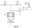
[0061] 図2Bに示すのは、作動を制御するための他の好ましい電気機械構成であり、デバイス・フレームからの放出を制御するために、電気動作型ソレノイド・バルブ110zを含む。この電気動作型ソレノイド・バルブ10zは、オープン・スプリンクラまたは他のフレーム・ボディ110xと一列となり、その上流にある。フレーム出口には密閉アセンブリがなく、ソレノイド・バルブ110zが常時閉鎖かまたは常時開放かに応じて、ソレノイド・バルブを開くためにしかるべく構成された電気信号をソレノイド・バルブ110zがコントローラ120から受信したときに、オープン・スプリンクラのフレーム・ボディ110xから水を流出させる。バルブ110zは、バルブ110zを開いたときにその動作圧力で流体をフレーム入口に送出するときに生ずる遅延が無視できる程度になるように、好ましくは、フレーム・ボディ110xに対して相対的に位置付けられる。システム100において使用する既知の電気動作型ソレノイド・バルブの例には、<http:// http://www.ascovalve.com/Common/PDFFiles/Product/8210R6.pdf>において入手可能な、ASCO(登録商標)技術データ・シート「2/2シリーズ8210:パイロット作動式一般サービス用ソレノイド・バルブ真鍮またはステンレス鋼本体3/8から21/2NPT」(2/2 Series 8210: Pilot Operated General Service Solenoid Valves Brass or Stainless Steel Bodies 3/8 to 2 1/2 NPT)に記載されている電気ソレノイド・バルブおよびその同等品を含むことができる。バルブ対フレーム・ボディが1対1の比率である1つの特定的なソレノイド・バルブ構成では、本システムは、火災に対処し、更に好ましくは鎮静化することにより、既知の浸水構成と比較して、占有枠および保管されている商品に対する損傷を更に限定し、更に好ましくは低減するように制御される、微小散水システム(controlled micro-deluge system)を効果的に設けることができる。
[0061] Shown in FIG. 2B is another preferred electromechanical configuration for controlling operation, including an electrically operated solenoid valve 110z for controlling release from the device frame. This electrically operated
[0062] 既に説明したような好ましいシステム100を設置し、実際の火災検査を受けた。5フィート(5ft)の公称隙間を定めるために45フィート(45ft)水平天井の下に、40フィート(40ft)の公称保管高さまで格納された、箱詰め非発泡グループAプラスチックのラック保管の上に、 複数の好ましい流体配給デバイス110および検出器130を設置した。更に具体的には、例えば、図2Bに示すように、19.2GPM/PSI1/2の実K−ファクタを定めるように、各々、25.2GPM/PSI1/2の公称K−ファクタを有する、ESFR型スプリンクラの16個のオープン・スプリンクラ・フレーム・ボディーおよび偏向部材を、流体配給アセンブリ内に、ソレノイド・バルブと共に配置した。各流体配給アセンブリの上および周囲には、1対の検出器130を配置した。配給デバイス110を10ft×10ftの間隔で設置し、25GPM/PSI1/2の公称K−ファクタと同等となる流量を供給するように、35psiの動作圧で水が供給される各スプリンクラから水を供給した。これらのアセンブリは、スプリンクラの偏向部材が天井よりも20インチ(20in)下に位置するように、天井の下に設置された。
[0062] A
[0063] スプリンクラ・アセンブリは、グループAプラスチック商品の上に設置した。この商品は、21in×21inの両面段ボール製のカートンを含み、カートン内には分離された部屋内に125個の結晶ポリスチレン製の空の16oxカップを収容した。双方向42in×42in×5inのスラットで作ったデッキ硬材製パレットによって、商品の各パレットを支持した。中央に二重列ラックを有するラック配置で、 商品を保管し、2つの単一列ターゲット・アレイ(single-row target array)を中央のラックの周囲に配置し、中央アレイとターゲット・アレイとの間に、図5Bに見られるように、4フィート(4ft)幅の通路幅W1、W2を定めた。中央の二重列ラック・アレイは、4つの96インチ・ベイと共に配置された高さ40ft、幅36インチのラック部材を含み、各列には8つの層があり、検査アレイ全域に公称6インチの長手方向および横断方向煙道空間がある。 [0063] The sprinkler assembly was installed on a Group A plastic item. This product contained a 21-inch by 21-inch double-sided cardboard carton that contained 125 empty 16 ox cups made of crystalline polystyrene in a separate room. Each pallet of the product was supported by a deck hardwood pallet made of bi-directional 42 in x 42 in x 5 in slats. In a rack arrangement with a double-row rack in the center, store goods and place two single-row target arrays around the center rack between the center array and the target array. As shown in FIG. 5B, passage widths W1 and W2 having a width of 4 feet (4 ft) were defined. The central double row rack array includes 40ft high, 36 inch wide rack members arranged with four 96 inch bays, each row has 8 layers, nominally 6 inches across the test array. There are longitudinal and transverse flue spaces.
[0064] 中央ラックの幾何学的中心を、4つの流体配給アセンブリ110の下に置いた。4オンス(4oz)のガソリンを滲入させポリエチレン・バッグ内に包んだ3in×3in長セルロース束によって、2つの半標準(half-standard)セルロース綿点火装置を製作した。中央の二重列ラック主アレイの中心から21インチずらして、点火装置を床上に位置付けた。点火装置を点火し、システム100の単一火災F検査を行った。システム100および好ましい方法は、検査火災を突き止め、既に説明したようにこの火災に対処するために、流体配給デバイス110を特定した。システム100は、32分の期間検査火災に対処し続け、検査の終了時に、商品を評価した。
[0064] The geometric center of the central rack was placed under the four
[0065] この検査火災は、鎮火のために構成された好ましいシステムが、保管されている商品に対する火災の影響を著しく低減する能力を例証する。動作させる合計9つの動作させる配給デバイスが特定され、点火の2分以内に動作した。9つの特定されたデバイスの中には、火災の直上および周囲にある4つの配給デバイス110q、110r、110s、110tが含まれる。これら4つの動作したデバイス110q、110r、110s、110tは、天井に向かう垂直方向、中央アレイ12aの端部に向かう前後方向、およびターゲット・アレイ12b、12cに向かう横方向において火災の伝搬を限定したことによって、点火を効果的に鎮静化した放出アレイを定めた。このようにこの火災の上および周囲において、4つの最も直接的で最も近い流体配給デバイス110q、110r、110s、110tによって、火災が閉じ込められた、または包囲された。
[0065] This inspection fire illustrates the ability of a preferred system configured for extinguishing to significantly reduce the impact of fire on stored goods. A total of nine operating delivery devices to be operated were identified and operated within 2 minutes of ignition. Among the nine identified devices are four distribution devices 110q, 110r, 110s, 110t directly above and around the fire. These four operated devices 110q, 110r, 110s, 110t limited fire propagation in the vertical direction towards the ceiling, in the front-rear direction towards the end of the central array 12a, and in the lateral direction towards the
[0066] 主アレイに対する損傷を、図5B、図6A、および図6Bにおいてグラフで示す。商品に対する損傷は、中央に配置されたパレットによって定められる中央アレイの中核部に集中した。この損傷を陰影で示す。アレイの端部に向かう方向では、火災の損傷は2つの中央ベイに限定された。カートンに対する損傷は最小に抑えられたことが観察された。したがって、1つの好ましい態様では、鎮火システムは、火災の上および周囲に最も近く配置された好ましい4つの流体配給デバイスによって定められた断面エリア内に火災を閉じ込めた。図6Aおよび図6Bを参照すると、火災の損傷は、縦方向でも、好ましい鎮火システムによって限定された、即ち、抑制された。更に具体的には、火災の損傷は、アレイの底部から、保管された商品の底部から6番目の層よりも上には広がらないように、垂直方向に限定された。鎮火の遂行が火災の伝搬を限定したと仮定すると、検査火災が通路を越えてターゲット・アレイ12b、12cに飛び火するのを防止する好ましいシステムの能力によっても、鎮火性能を更に特徴付けることができる。
[0066] Damage to the main array is shown graphically in FIGS. 5B, 6A, and 6B. Damage to the product was concentrated in the core of the central array defined by the centrally located pallet. This damage is indicated by shading. In the direction toward the end of the array, fire damage was limited to the two central bays. It was observed that damage to the carton was minimized. Thus, in one preferred embodiment, the fire suppression system confined the fire within a cross-sectional area defined by four preferred fluid delivery devices located closest to and around the fire. Referring to FIGS. 6A and 6B, fire damage was limited, i.e., suppressed by the preferred fire suppression system, also in the longitudinal direction. More specifically, fire damage was limited in the vertical direction so that it did not spread from the bottom of the array above the sixth layer from the bottom of the stored goods. Assuming that the performance of fire suppression limited fire propagation, fire suppression performance can also be further characterized by the ability of the preferred system to prevent inspection fires from jumping into the
[0067] 鎮静化の性能は、1つ以上のパラメータまたはその組み合わせを満たすか否かによって観察することができる。例えば、縦方向の損傷は、商品の6層以下に限定することができる。代わりにまたは加えて、縦方向の損傷は、検査商品の全層数の75%以下に限定することができる。また、横方向の損傷も、鎮静化性能を特徴付けるために定量化することができる。例えば、鎮静化性能に関与する(subject to)横方向の損傷は、2つのパレット以下に限定することができ、更に好ましくは、アレイの端部に向かう方向において1つ以下のパレットである。 [0067] Sedation performance can be observed by satisfying one or more parameters or combinations thereof. For example, longitudinal damage can be limited to six or fewer layers of merchandise. Alternatively or additionally, the longitudinal damage can be limited to 75% or less of the total number of layers of the inspected product. Lateral damage can also be quantified to characterize sedation performance. For example, lateral damage that is subject to sedation performance can be limited to no more than two pallets, and more preferably no more than one pallet in the direction toward the end of the array.
[0068] 追加の火災検査によって、本明細書において説明した好ましいシステムおよび方法は、現在の設置規格の下では利用できない高さおよび配置とした露出発泡プラスチック商品の天井単独保護においても使用できることが示された。例えば、1つの好ましいシステム設置では、複数の好ましい流体配給デバイス110および検出器130を、露出発泡グループAプラスチックのラック保管の上に設置することができる。露出発泡グループAプラスチックは、5フィート(5ft)から20フィート(20ft)までに及ぶ公称隙間を定めるために、45フィート(45ft)水平天井の下で、25(25ft)から40フィート(40ft)までに及ぶ公称保管高さに格納される。天井は十分な高さがあることを条件に、本明細書におけるシステムおよび方法の好ましい実施形態は、最大50から55フィート(50〜55ft)まで保護することができる。好ましい1つの保管配置では、天井の高さが48(48ft)であり、公称保管高さは43フィート(43ft)である。
[0068] Additional fire inspections show that the preferred systems and methods described herein can also be used in ceiling protection of exposed foam plastic items at heights and locations that are not available under current installation standards. It was done. For example, in one preferred system installation, a plurality of preferred
[0069] 好ましいシステムの1つの特定的な実施形態では、ESFRタイプのスプリンクラ・フレーム・ボディのグループが、好ましくは、例えば図2Aに示すように、内部密閉アセンブリおよび偏向部材を有し、各々25.2GPM/PSI1/2の公称K−ファクタを有する流体配給アセンブリにおける電気動作アクチュエータと共に配置される。各流体配給アセンブリの上および周囲には、1対の検出器130が配置されている。排水デバイス110は、好ましくは、ループ型配管システムにおいて10ft×10ftの間隔で設置され、1,95gpm・ft2という好ましい放出密度を得るために、60psiの動作圧力で水を供給される。流体配給デバイスは、好ましくは、天井の下において18インチ(18in)の好ましいディフレクタ/天井間距離Sのところに偏向部材を位置付けるように、天井の下に設置される。各ディフレクタおよび流体配給デバイスは、本明細書において説明したように、火災の検出および1つ以上の流体配給アセンブリを動作させるために、好ましくは集中コントローラに結合される。本システムおよびそのコントローラ120は、好ましくは、検出された火災に対処する初期放出アレイを形成するために、9つの配給デバイス110を特定するようにプログラミングされる。
[0069] In one particular embodiment of the preferred system, a group of ESFR type sprinkler frame bodies preferably has an internal sealing assembly and a deflecting member, for example as shown in FIG. Placed with an electrically actuated actuator in a fluid delivery assembly having a nominal K-factor of 2 GPM / PSI 1/2 . A pair of
[0070] 以上、ある種の実施形態を参照しながら本発明を開示したが、説明した実施形態には、添付した請求項に定められる、本発明の範囲(sphere and scope)から逸脱することなく、多数の修正、改変、および変更が可能である。したがって、本発明は、説明した実施形態に限定されるのではなく、以下の請求項の文言およびその均等物によって定められる最大範囲を有することを意図している。
[0070] While the invention has been disclosed with reference to certain embodiments, it will be understood that the embodiments described are not limited to the scope of the invention as defined in the appended claims. Numerous modifications, alterations, and changes are possible. Accordingly, the present invention is not intended to be limited to the embodiments described, but is to be construed as having the maximum scope defined by the following claims language and equivalents thereof.
Claims (54)
前記天井の下において、および公称20ftから最大公称保管高さの55ftまでに及ぶ公称保管高さを有する倉庫占有枠における高積層保管商品の上に配置された複数の流体配給デバイスと、
前記倉庫占有枠における火災を鎮静化する手段と、
を含む、システム。 A ceiling-only fire protection system for a warehouse occupancy frame having a ceiling that defines a nominal ceiling height of 30 feet or more,
A plurality of fluid delivery devices disposed under the ceiling and on a high stack storage article in a warehouse occupancy frame having a nominal storage height ranging from a nominal 20 ft to a maximum nominal storage height of 55 ft;
Means to mitigate the fire in the warehouse occupancy frame;
Including the system.
前記流体配給デバイスを給水所に相互接続する導管網を含む流体配給システムと、
前記占有枠を監視して火災を発見する複数の検出器と、
前記火災を検出し突き止めるために前記複数の検出器に結合されたコントローラであって、前記火災の上および周囲に放出アレイを形成するために、選択数の流体配給デバイスを特定しその動作を制御するために、前記複数の配給デバイスに結合された、コントローラと、
を含み、前記コントローラが、
前記検出器の各々からの入力信号の受信のために、前記複数の検出器の各々に結合された入力コンポーネントと、
前記火災の成長における閾値時機を判定する処理コンポーネントと、
前記閾値時機に応答して、前記選択流体配給デバイスの各々の動作のために出力信号を生成する出力コンポーネントと、
を含む、システム。 The system of claim 1, wherein said means is
A fluid distribution system including a conduit network interconnecting the fluid distribution device to a water station;
A plurality of detectors for monitoring the occupation frame and detecting a fire;
A controller coupled to the plurality of detectors for detecting and locating the fire, identifying a selected number of fluid delivery devices and controlling their operation to form a discharge array on and around the fire A controller coupled to the plurality of distribution devices;
The controller includes:
An input component coupled to each of the plurality of detectors for receiving an input signal from each of the detectors;
A processing component for determining a threshold timing in the growth of the fire;
An output component that generates an output signal for each operation of the selected fluid delivery device in response to the threshold timing;
Including the system.
公称20ftから最大公称保管高さの55ftまでに及ぶ公称保管高さを有する倉庫占有枠における保管商品において火災を検出するステップと、
前記倉庫占有枠における火災を鎮静化するステップと、
を含む、方法。 A ceiling-only fire prevention method for a warehouse occupancy frame having a ceiling with a nominal ceiling height of 30 feet or more,
Detecting a fire in stored goods in a warehouse occupancy having a nominal storage height ranging from a nominal 20 ft to a maximum nominal storage height of 55 ft;
Soothing the fire in the warehouse occupancy frame;
Including the method.
前記占有枠を監視している複数の検出器からのデータ読み取り値に基づいて、火災成長のエリアを定めるステップと、
前記火災成長のエリアにおいて検出器の数を決定するステップと、
読み取り値が最高の検出器を判定するステップと、
を含む、方法。 42. The method of claim 41, wherein the step of locating the source of the fire comprises
Determining a fire growth area based on data readings from a plurality of detectors monitoring the occupancy window;
Determining the number of detectors in the area of fire growth;
Determining the detector with the highest reading;
Including the method.
火災の閾値検出に関連付けられた第1配給デバイスを決定するステップと、
前記第1配給デバイスに隣接する複数の配給デバイスを特定するステップであって、前記複数の隣接する配給デバイスおよび前記第1配給デバイスが、4または9の内任意の1つである総数を定め、前記総数がユーザによって定められる、ステップと、
を含む、方法。 52. The method of claim 51, wherein the step of making a unified decision comprises:
Determining a first delivery device associated with fire threshold detection;
Identifying a plurality of distribution devices adjacent to the first distribution device, the total number of the plurality of adjacent distribution devices and the first distribution device being any one of 4 or 9, The total number is defined by a user; and
Including the method.
閾値と一致するまたはこれを超過する第1検出器を特定するステップと、
前記第1検出器と関連付けられた第1固定パターンの流体配給デバイスを動作させるステップと、
前記第1固定パターンとは異なる第2固定パターンの流体配給デバイスを動作させるステップと、
前記第1および第2固定パターンとは異なる第3固定パターンの流体配給デバイスを動作させるステップと、
を含む、方法。
52. The method of claim 51, wherein the step of making a unified decision comprises:
Identifying a first detector that matches or exceeds a threshold;
Operating a first fixed pattern fluid delivery device associated with the first detector;
Operating a fluid delivery device of a second fixed pattern different from the first fixed pattern;
Operating a fluid delivery device of a third fixed pattern different from the first and second fixed patterns;
Including the method.
Applications Claiming Priority (7)
| Application Number | Priority Date | Filing Date | Title |
|---|---|---|---|
| US201361920314P | 2013-12-23 | 2013-12-23 | |
| US201361920274P | 2013-12-23 | 2013-12-23 | |
| US61/920,274 | 2013-12-23 | ||
| US61/920,314 | 2013-12-23 | ||
| US201462009778P | 2014-06-09 | 2014-06-09 | |
| US62/009,778 | 2014-06-09 | ||
| PCT/US2014/072246 WO2015100367A1 (en) | 2013-12-23 | 2014-12-23 | Controlled system and methods for storage fire protection |
Publications (2)
| Publication Number | Publication Date |
|---|---|
| JP2017501818A true JP2017501818A (en) | 2017-01-19 |
| JP2017501818A5 JP2017501818A5 (en) | 2018-02-08 |
Family
ID=52350378
Family Applications (1)
| Application Number | Title | Priority Date | Filing Date |
|---|---|---|---|
| JP2016543146A Pending JP2017501818A (en) | 2013-12-23 | 2014-12-23 | Warehouse fire prevention control system and method |
Country Status (13)
| Country | Link |
|---|---|
| US (3) | US20170007864A1 (en) |
| EP (2) | EP4275765A3 (en) |
| JP (1) | JP2017501818A (en) |
| KR (1) | KR20160102302A (en) |
| CN (1) | CN105980017B (en) |
| AU (2) | AU2014369873B2 (en) |
| BR (1) | BR112016014763A2 (en) |
| CA (1) | CA2934680C (en) |
| CL (1) | CL2016001618A1 (en) |
| IL (1) | IL246323B (en) |
| RU (1) | RU2697112C2 (en) |
| SG (1) | SG11201604999RA (en) |
| WO (1) | WO2015100367A1 (en) |
Families Citing this family (15)
| Publication number | Priority date | Publication date | Assignee | Title |
|---|---|---|---|---|
| US10646735B2 (en) * | 2014-07-28 | 2020-05-12 | Tyco Fire Products Lp | System and methods for wet system fire protection |
| WO2017214624A2 (en) * | 2016-06-10 | 2017-12-14 | Tyco Fire Products Lp | Fire protection systems and methods for storage |
| US20180200552A1 (en) * | 2017-01-16 | 2018-07-19 | Shalom Wertsberger | Fire containment system, devices and methods for same and for firefighting systems |
| NL2020430B1 (en) * | 2017-07-18 | 2019-02-25 | Unica Fire Safety B V | Sprinkler system. |
| US11007388B2 (en) * | 2018-08-17 | 2021-05-18 | Viking Group, Inc. | Automatic fire sprinklers, systems and methods for suppression fire protection of high hazard commodities including commodities stored in rack arrangements beneath ceilings of up to fifty-five feet in height |
| KR101978745B1 (en) * | 2018-09-05 | 2019-05-15 | 정희섭 | Fire extinguishing control device using a sprinkler in a rack for extinguishing a fire generated in a warehouse rack having a plurality of stacking spaces and operating method thereof |
| US11511145B1 (en) * | 2019-06-19 | 2022-11-29 | Minimax Viking Research & Development Gmbh | Fast response glass bulb thermal trigger arrangements and methods thereof for large orifice suppression fire protection sprinklers |
| WO2021150606A1 (en) * | 2020-01-24 | 2021-07-29 | Minimax Viking Research & Development Gmbh | Zone validation test method for a fire suppression device |
| AU2021223188A1 (en) * | 2020-02-22 | 2022-10-20 | Water-Dome Ltd | Community outdoor fire defense |
| CN111577025A (en) * | 2020-04-24 | 2020-08-25 | 德施曼机电(中国)有限公司 | Intelligent lock with fire alarm function and alarm method |
| KR102179900B1 (en) * | 2020-07-07 | 2020-11-17 | 정희섭 | Fire control system apparatus capable of controling fire for loading space and operating method thereof |
| US20230356014A1 (en) * | 2020-10-29 | 2023-11-09 | Tyco Fire Products Lp | Controlled system and methods of automated storage and retrieval system fire protection |
| KR20220060028A (en) * | 2020-11-02 | 2022-05-11 | 삼성디스플레이 주식회사 | Window manufacturing system |
| AU2021402248A1 (en) * | 2020-12-17 | 2023-05-11 | Tyco Fire Products Lp | Controlled system and methods of storage structure fire protection |
| RU2760650C1 (en) * | 2021-01-29 | 2021-11-29 | Общество с ограниченной ответственностью «Инженерный центр пожарной робототехники «ЭФЭР» | Robotic fire extinguishing unit |
Citations (3)
| Publication number | Priority date | Publication date | Assignee | Title |
|---|---|---|---|---|
| JPH10248954A (en) * | 1997-03-17 | 1998-09-22 | Nohmi Bosai Ltd | Sprinkler fire extinguishing equipment |
| JP2008168114A (en) * | 2006-09-05 | 2008-07-24 | Reliable Automatic Sprinkler Co Inc | Automatic fire protection sprinkler with extended body |
| JP2009516533A (en) * | 2005-10-21 | 2009-04-23 | タイコ・フアイヤー・プロダクツ・エルピー | Ceiling-only dry sprinkler system and method for warehouse fires |
Family Cites Families (22)
| Publication number | Priority date | Publication date | Assignee | Title |
|---|---|---|---|---|
| BE786098A (en) | 1971-07-12 | 1972-11-03 | Graviner Colnbrook Ltd | FIRE EXTINGUISHING SYSTEMS |
| US3834463A (en) | 1973-02-28 | 1974-09-10 | Itt | Sensitive sprinkler |
| US3863720A (en) | 1974-03-13 | 1975-02-04 | Richard J Young | Electrical resistance fusible link for a sprinkler head |
| SE413579B (en) | 1977-10-20 | 1980-06-09 | Gw Sprinkler As | LIQUID DISTRIBUTOR FOR A FIRE LIGHTING ESTABLISHMENT |
| SE413626B (en) * | 1977-11-23 | 1980-06-16 | Bofors Ab | SET AND DEVICE FOR EFFECTING A FIREPROOF SPRINKLER |
| CA2036881C (en) | 1991-02-22 | 1994-06-28 | Jean-Pierre Asselin | Fire emergency, sprinkling control system and method thereof |
| US7165624B1 (en) | 1998-05-15 | 2007-01-23 | Grinnell Corporation | Early suppression fast response fire protection sprinkler |
| US6039124A (en) * | 1998-09-17 | 2000-03-21 | The United States Of America As Represented By The Secretary Of The Navy | Electrical detector actuated magazine sprinkler (EDAMS) system |
| DE19945856B4 (en) * | 1999-09-24 | 2005-12-29 | Robert Bosch Gmbh | Sprinkler device with a valve for extinguishing liquid |
| KR100342703B1 (en) * | 2000-02-21 | 2002-07-04 | 길종진 | Springkler apparatus and control method there of |
| US6685104B1 (en) * | 2002-07-17 | 2004-02-03 | Ardele Y. Float | Landscape sprinkling systems |
| US7201234B2 (en) * | 2004-12-01 | 2007-04-10 | Tyco Fire Products Lp | Residential fire sprinkler |
| US20060289174A1 (en) * | 2005-06-22 | 2006-12-28 | Hong-Zeng Yu | Deluge-like sprinkler fire scheme using high thermal sensitivity and high temperature rating sensing elements |
| CN100429679C (en) | 2005-12-19 | 2008-10-29 | 首安工业消防有限公司 | Data fusing warning method using one line type temperature sensing element |
| US10532236B2 (en) * | 2008-02-13 | 2020-01-14 | The Reliable Automatic Sprinkler Co., Inc. | Method of fire protection for storage occupancies utilizing a plurality of pendent control mode specific application extended coverage fire protection sprinklers |
| RU2517813C2 (en) * | 2008-12-31 | 2014-05-27 | Санг-Сун ЛИ | Sprinkler with integrated valve and fire extinguishing system using it |
| RU95528U1 (en) | 2009-02-05 | 2010-07-10 | Общество с ограниченной ответственностью "Холдинг Гефест" | FIRE EXTINGUISHING PLANT |
| RU2414966C1 (en) | 2009-09-14 | 2011-03-27 | Общество с ограниченной ответственностью "Холдинг Гефест" (ООО "Холдинг Гефест") | Water extinguishing system |
| US8511397B2 (en) * | 2010-01-12 | 2013-08-20 | Kidde Technologies, Inc. | Highly integrated data bus automatic fire extinguishing system |
| US20120118591A1 (en) * | 2010-11-12 | 2012-05-17 | Ping-Li Yen | Water, foam and compressed air protection against fire, in or associated with structures |
| WO2014026049A2 (en) * | 2012-08-10 | 2014-02-13 | The Reliable Automatic Sprinkler Co., Inc. | In-rack storage fire protection sprinkler system |
| EP2919863B1 (en) | 2012-11-13 | 2020-03-18 | Marioff Corporation Oy | Temperature derivative based launch method for fire suppression systems |
-
2014
- 2014-12-23 RU RU2016130279A patent/RU2697112C2/en active
- 2014-12-23 CA CA2934680A patent/CA2934680C/en active Active
- 2014-12-23 EP EP23200900.1A patent/EP4275765A3/en active Pending
- 2014-12-23 KR KR1020167020212A patent/KR20160102302A/en not_active Application Discontinuation
- 2014-12-23 WO PCT/US2014/072246 patent/WO2015100367A1/en active Application Filing
- 2014-12-23 BR BR112016014763A patent/BR112016014763A2/en not_active IP Right Cessation
- 2014-12-23 AU AU2014369873A patent/AU2014369873B2/en active Active
- 2014-12-23 US US15/107,049 patent/US20170007864A1/en not_active Abandoned
- 2014-12-23 EP EP14827683.5A patent/EP3086864B1/en active Active
- 2014-12-23 CN CN201480075537.2A patent/CN105980017B/en active Active
- 2014-12-23 SG SG11201604999RA patent/SG11201604999RA/en unknown
- 2014-12-23 JP JP2016543146A patent/JP2017501818A/en active Pending
-
2016
- 2016-06-19 IL IL246323A patent/IL246323B/en active IP Right Grant
- 2016-06-23 CL CL2016001618A patent/CL2016001618A1/en unknown
-
2019
- 2019-03-13 US US16/352,426 patent/US11033764B2/en active Active
-
2020
- 2020-01-10 AU AU2020200222A patent/AU2020200222B2/en active Active
-
2021
- 2021-05-24 US US17/327,913 patent/US20210275844A1/en active Pending
Patent Citations (3)
| Publication number | Priority date | Publication date | Assignee | Title |
|---|---|---|---|---|
| JPH10248954A (en) * | 1997-03-17 | 1998-09-22 | Nohmi Bosai Ltd | Sprinkler fire extinguishing equipment |
| JP2009516533A (en) * | 2005-10-21 | 2009-04-23 | タイコ・フアイヤー・プロダクツ・エルピー | Ceiling-only dry sprinkler system and method for warehouse fires |
| JP2008168114A (en) * | 2006-09-05 | 2008-07-24 | Reliable Automatic Sprinkler Co Inc | Automatic fire protection sprinkler with extended body |
Also Published As
| Publication number | Publication date |
|---|---|
| AU2014369873A1 (en) | 2016-07-07 |
| WO2015100367A1 (en) | 2015-07-02 |
| AU2020200222B2 (en) | 2021-07-15 |
| SG11201604999RA (en) | 2016-07-28 |
| CA2934680C (en) | 2022-03-15 |
| CN105980017B (en) | 2022-01-14 |
| RU2016130279A (en) | 2018-01-30 |
| RU2697112C2 (en) | 2019-08-12 |
| CL2016001618A1 (en) | 2017-03-24 |
| EP3086864A1 (en) | 2016-11-02 |
| EP4275765A3 (en) | 2024-02-14 |
| EP3086864B1 (en) | 2023-10-04 |
| RU2016130279A3 (en) | 2018-07-27 |
| US20210275844A1 (en) | 2021-09-09 |
| US20170007864A1 (en) | 2017-01-12 |
| AU2020200222A1 (en) | 2020-02-06 |
| EP4275765A2 (en) | 2023-11-15 |
| KR20160102302A (en) | 2016-08-29 |
| CN105980017A (en) | 2016-09-28 |
| BR112016014763A2 (en) | 2017-08-08 |
| US11033764B2 (en) | 2021-06-15 |
| IL246323A0 (en) | 2016-07-31 |
| CA2934680A1 (en) | 2015-07-02 |
| IL246323B (en) | 2021-04-29 |
| AU2014369873B2 (en) | 2019-10-10 |
| US20190209879A1 (en) | 2019-07-11 |
Similar Documents
| Publication | Publication Date | Title |
|---|---|---|
| AU2020200222B2 (en) | Controlled system and methods for storage fire protection | |
| JP7204707B2 (en) | Warehouse fire control system and method | |
| EP3151928B1 (en) | Controlled system and methods for storage fire protection | |
| US11752373B2 (en) | Wet fire protection systems and methods for storage |
Legal Events
| Date | Code | Title | Description |
|---|---|---|---|
| A521 | Request for written amendment filed |
Free format text: JAPANESE INTERMEDIATE CODE: A523 Effective date: 20171221 |
|
| A621 | Written request for application examination |
Free format text: JAPANESE INTERMEDIATE CODE: A621 Effective date: 20171221 |
|
| A521 | Request for written amendment filed |
Free format text: JAPANESE INTERMEDIATE CODE: A821 Effective date: 20180202 |
|
| A977 | Report on retrieval |
Free format text: JAPANESE INTERMEDIATE CODE: A971007 Effective date: 20181221 |
|
| A131 | Notification of reasons for refusal |
Free format text: JAPANESE INTERMEDIATE CODE: A131 Effective date: 20181227 |
|
| A02 | Decision of refusal |
Free format text: JAPANESE INTERMEDIATE CODE: A02 Effective date: 20190718 |