JP2017227767A - Display device - Google Patents
Display device Download PDFInfo
- Publication number
- JP2017227767A JP2017227767A JP2016123795A JP2016123795A JP2017227767A JP 2017227767 A JP2017227767 A JP 2017227767A JP 2016123795 A JP2016123795 A JP 2016123795A JP 2016123795 A JP2016123795 A JP 2016123795A JP 2017227767 A JP2017227767 A JP 2017227767A
- Authority
- JP
- Japan
- Prior art keywords
- liquid crystal
- crystal panel
- adhesive
- display device
- transparent substrate
- Prior art date
- Legal status (The legal status is an assumption and is not a legal conclusion. Google has not performed a legal analysis and makes no representation as to the accuracy of the status listed.)
- Pending
Links
Images


Abstract
Description
本発明は、表示装置に関する。 The present invention relates to a display device.
近年、ウィンドウガラス等の透明基板に、粘着剤を介して液晶パネルを貼付することにより、デジタルサイネージ等の表示装置を構成することが提案されている(例えば、特許文献1参照)。この表示装置によれば、通行人は、店舗、オフィスの外部からウィンドウガラスを介して液晶パネルの表示内容を確認できるため、看板、広告等として有効利用することができる。 In recent years, it has been proposed to construct a display device such as a digital signage by attaching a liquid crystal panel to a transparent substrate such as a window glass via an adhesive (see, for example, Patent Document 1). According to this display device, a passerby can check the display content of the liquid crystal panel from the outside of the store or office via the window glass, so that it can be effectively used as a signboard, an advertisement, or the like.
図9(A)、(B)、(C)は、従来の表示装置100の組立手順の一例を示した説明図である。
FIGS. 9A, 9 </ b> B, and 9 </ b> C are explanatory diagrams illustrating an example of an assembly procedure of the
図9(A)に示すように、透明基板102の被貼付面102Aに粘着剤104を塗布し、この粘着剤104に液晶パネル106の画像表示面106Aを隙間なく貼付する。次に、図9(B)に示すように、バックライト108とバックライト108を保持するケース110とからなる照明部材112を、液晶パネル106の背面106B側から液晶パネル106を覆うように被貼付面102Aに固定する。この固定作業は、まず、ケース110の枠部110Aの端面110Bを被貼付面102Aに当接し、液晶パネル106の周縁部106Cの端面106Dを、所定の隙間aを介して枠部110Aにより包囲する。この作業によって、ケース110(照明部材112)が液晶パネル106に対して位置決めされる。この後、図9(C)に示すように、L字状の取付部材114を利用してケース110を被貼付面102Aに固定する。具体的には、枠部110Aの外側に位置する被貼付面102Aに両面接着テープ116を接着し、この両面接着テープ116に取付部材114を貼合する。次に、ボルト等の締結部材118を利用して、取付部材114に枠部110Aを固定する。これにより、ケース110(照明部材112)が取付部材114と両面接着テープ116を介して被貼付面102Aに接合される。このような作業を経ることによって、表示装置100が組み立てられる。
As shown in FIG. 9A, the
このような構造の表示装置では、透明基板102の被貼付面102Aに形成される接着領域であって、両面接着テープ116の枠状の接着領域に、遮光部120が設けられる。この遮光部120によって囲まれる矩形領域が液晶パネル106の画像表示面の領域と一致する。また、遮光部120によって取付部材114や電気配線基板を隠すことにより、表示装置100の意匠性を損なわせないようにしている。
In the display device having such a structure, the light-
表示装置100のデザインバリエーションの一つとして、遮光部120の面積を小さくする需要が想定される。しかし、遮光部120の面積を小さくすると、両面接着テープ116の面積が小さくなり、両面接着テープ116の接着力の低下に起因して、両面接着テープ116のみで透明基板102に支えられている照明部材112が、透明基板102からずり落ちてしまい、バックライト108で液晶パネル106を適正に照明することができなくなるおそれがある。
As one of the design variations of the
したがって、従来の表示装置100では、照明部材112を保持する観点から、両面接着テープ116の面積を小さくできず、その結果、遮光部120の面積を小さくすることが困難であり、様々なデザインの表示装置を作れないという問題があった。
Therefore, in the
本発明は、このような事情に鑑みてなされたもので、画像表示面を囲む遮光部の面積を小さくするデザインを実現できる表示装置の提供を目的とする。 The present invention has been made in view of such circumstances, and an object of the present invention is to provide a display device capable of realizing a design for reducing the area of a light shielding portion surrounding an image display surface.
本発明の表示装置の第1態様は、本発明の目的を達成するために、略鉛直方向に沿って配置される透明基板の一方面に、液晶パネルおよび照明部材がこの順に有する表示装置であって、液晶パネルは、第1粘着剤を介して透明基板の一方面に貼合されており、照明部材は、バックライトと、バックライトを収容し枠部および底面を有する略凹状のケースとを有し、照明部材は、ケースの枠部の外側面に取り付けられる1以上の取付部材と、取付部材を透明基板の一方面に貼合する第2粘着剤とにより、透明基板の一方面に接合されており、ケースは、ケースの上側の枠部の内側面が液晶パネルの少なくとも上側の端面と接している。 In order to achieve the object of the present invention, a first aspect of the display device of the present invention is a display device in which a liquid crystal panel and an illuminating member are arranged in this order on one surface of a transparent substrate arranged along a substantially vertical direction. The liquid crystal panel is bonded to one surface of the transparent substrate via the first adhesive, and the illumination member includes a backlight and a substantially concave case that houses the backlight and has a frame portion and a bottom surface. The lighting member is bonded to one surface of the transparent substrate by one or more mounting members that are attached to the outer surface of the frame portion of the case and a second adhesive that bonds the mounting member to one surface of the transparent substrate. In the case, the inner side surface of the upper frame portion of the case is in contact with at least the upper end surface of the liquid crystal panel.
本発明の表示装置の第2態様は、本発明の目的を達成するために、略鉛直方向に沿って配置される透明基板の一方面に、液晶パネルおよび照明部材がこの順に有する表示装置であって、液晶パネルは、第1粘着剤を介して透明基板の一方面に貼合されており、照明部材は、バックライトと、バックライトを収容し枠部および底面を有する略凹状のケースとを有し、照明部材は、ケースの枠部の外側面に取り付けられる1以上の取付部材と、取付部材を透明基板の一方面に貼合する第2粘着剤とにより、透明基板の一方面に接合されており、取付部材は、液晶パネルの少なくとも上側の端面と接している。 In order to achieve the object of the present invention, a second aspect of the display device of the present invention is a display device in which a liquid crystal panel and an illumination member have in this order on one surface of a transparent substrate arranged along a substantially vertical direction. The liquid crystal panel is bonded to one surface of the transparent substrate via the first adhesive, and the illumination member includes a backlight and a substantially concave case that houses the backlight and has a frame portion and a bottom surface. The lighting member is bonded to one surface of the transparent substrate by one or more mounting members that are attached to the outer surface of the frame portion of the case and a second adhesive that bonds the mounting member to one surface of the transparent substrate. The attachment member is in contact with at least the upper end surface of the liquid crystal panel.
本発明によれば、照明部材を透明基板に支持する荷重の一部を、液晶パネル側の第1粘着剤に持たせることができるので、第2粘着剤にかかる荷重を小さくできる。そのため、第2粘着剤の接着面積を小さくできる。その結果、本発明の表示装置によれば、画像表示面を囲む遮光部の面積を小さくするデザインを実現できる。 According to the present invention, since the first pressure-sensitive adhesive on the liquid crystal panel side can have a part of the load for supporting the lighting member on the transparent substrate, the load applied to the second pressure-sensitive adhesive can be reduced. Therefore, the adhesion area of the second pressure-sensitive adhesive can be reduced. As a result, according to the display device of the present invention, it is possible to realize a design that reduces the area of the light shielding portion surrounding the image display surface.
第1態様では、ケースの上側の枠部の内側面と液晶パネルの上側の端面とを接触させることで、照明部材を透明基板に支持する荷重の一部を、液晶パネル側の第1粘着剤に持たせることができる。 In the first aspect, by bringing the inner side surface of the upper frame portion of the case into contact with the upper end surface of the liquid crystal panel, a part of the load for supporting the illumination member on the transparent substrate is used as the first pressure-sensitive adhesive on the liquid crystal panel side. Can have.
第2態様では、取付部材と液晶パネルの上側の端面とを接触させることで、照明部材を透明基板に支持する荷重の一部を、液晶パネル側の第1粘着剤に持たせることができる。 In the second aspect, the first pressure-sensitive adhesive on the liquid crystal panel side can have a part of the load for supporting the illumination member on the transparent substrate by bringing the attachment member and the upper end surface of the liquid crystal panel into contact with each other.
本発明の他の態様は、照明部材のケースの上側の枠部の内側面又は取付部材は、液晶パネルの少なくとも上側の端面に中間支持部材を介して接することが好ましい。 In another aspect of the present invention, it is preferable that the inner side surface or the mounting member of the upper frame portion of the case of the lighting member is in contact with at least the upper end surface of the liquid crystal panel via an intermediate support member.
本態様によれば、ケースの上側の枠部の内側面又は取付部材を、液晶パネルの上側の端面に中間支持部材を介して接触させることで、照明部材を透明基板に支持する荷重の一部を、液晶パネル側の第1粘着剤に持たせることができる。 According to this aspect, a part of the load for supporting the lighting member on the transparent substrate by bringing the inner side surface or the mounting member of the upper frame portion of the case into contact with the upper end surface of the liquid crystal panel via the intermediate support member Can be imparted to the first pressure-sensitive adhesive on the liquid crystal panel side.
また、本発明の他の態様では、中間支持部材のヤング率が0.5GPa〜3GPaであることが好ましい。 Moreover, in another aspect of the present invention, the intermediate support member preferably has a Young's modulus of 0.5 GPa to 3 GPa.
また、本発明の他の態様では、第1粘着剤は、25℃で1Hzにおけるせん断弾性率が1×10²Pa〜1×10⁶Paであることが好ましい。 Moreover, in another aspect of the present invention, the first pressure-sensitive adhesive preferably has a shear elastic modulus of 1 × 10 2 Pa to 1 × 10 6 Pa at 25 ° C. and 1 Hz.
また、本発明の他の態様は、透明基板は、第1透明基板と第2透明基板とを有し、第1透明基板の一方面と第2透明基板の他方面とが第3粘着剤によって貼付され、第2透明基板の一方面側に液晶パネル、第1粘着剤、照明部材、取付部材、第2粘着剤および遮光部が備えられることが好ましい。 According to another aspect of the present invention, the transparent substrate has a first transparent substrate and a second transparent substrate, and one surface of the first transparent substrate and the other surface of the second transparent substrate are formed by the third adhesive. It is preferable that a liquid crystal panel, a first pressure-sensitive adhesive, a lighting member, a mounting member, a second pressure-sensitive adhesive, and a light-shielding part are provided on one side of the second transparent substrate.
本発明の表示装置によれば、画像表示面を囲む遮光部の面積を小さくできるので、従来では実現が困難であったデザインの表示装置を提供できる。 According to the display device of the present invention, since the area of the light shielding portion surrounding the image display surface can be reduced, it is possible to provide a display device having a design that has been difficult to realize in the past.
以下、図面に従って、本発明に係る表示装置の好ましい実施形態について説明する。本発明は、以下の実施形態に限定されるものではなく、本発明の範囲であれば、以下の実施形態に種々の変形および置換を加えることができる。 Hereinafter, preferred embodiments of a display device according to the present invention will be described with reference to the drawings. The present invention is not limited to the following embodiments, and various modifications and substitutions can be made to the following embodiments within the scope of the present invention.
ここで、本願明細書で説明する「透明基板」とは、透明基板の一方面に液晶パネルが設けられ、透明基板の他方面から液晶パネルの表示画像を視認した際に、表示画像の全体又は一部が光学的な歪をほとんど受けることなく透明基板を通して視認できる程度の透明性を有する基板を指す。したがって、「透明基板」は、液晶パネルから透明基板に入射する光の一部が透明基板によって吸収されたり、反射されたりしても、又は光学的な位相の変化等によって可視光線透過率が低いものであっても、透明基板を通して光学的な歪がほとんどなく液晶パネルの表示画像を視認できるものであればよい。また、透明基板とは、複数枚の透明基板を粘着剤によって貼付した構成でもよい。この透明基板については、図面(図8)を用いて後述する。 Here, the “transparent substrate” described in the present specification means that a liquid crystal panel is provided on one surface of the transparent substrate, and when the display image of the liquid crystal panel is viewed from the other surface of the transparent substrate, the entire display image or It refers to a substrate having a transparency that is partially visible through a transparent substrate with almost no optical distortion. Therefore, the “transparent substrate” has a low visible light transmittance even if a part of light incident on the transparent substrate from the liquid crystal panel is absorbed or reflected by the transparent substrate or due to a change in optical phase or the like. Even if it is a thing, what is necessary is just to be able to visually recognize the display image of a liquid crystal panel with almost no optical distortion through a transparent substrate. Moreover, the structure which affixed the several transparent substrate with the adhesive may be sufficient as a transparent substrate. This transparent substrate will be described later with reference to the drawing (FIG. 8).
以下、主たる実施形態では略鉛直方向に沿って配置される透明基板として、ガラス板や、ポリカーボネート、ポリメチルメタクリレート等の透明の樹脂板を使用できる。また、透明基板として、複層ガラス、合わせガラス、ガラス板と樹脂板との積層体を使用できる。 Hereinafter, in the main embodiment, a transparent resin plate such as a glass plate, polycarbonate, or polymethyl methacrylate can be used as the transparent substrate disposed along the substantially vertical direction. Moreover, as a transparent substrate, a laminated glass, laminated glass, and a laminate of a glass plate and a resin plate can be used.
透明基板としては、液晶パネルからの射出光や反射光に対して透明性が高く、耐光性、低複屈折性、高い平面精度、耐表面擦傷性、高い機械的強度を有する観点から、ガラス板を用いることが好ましい。 As a transparent substrate, a glass plate is highly transparent with respect to light emitted from and reflected from a liquid crystal panel, and has light resistance, low birefringence, high planar accuracy, surface scratch resistance, and high mechanical strength. Is preferably used.
ガラス板の材料としては、ソーダライムガラス等の構造物の開口部や、内装部材などの建材として広く使用されているものが挙げられる。また、鉄分がより低く、青みの少ない高透過ガラスを用いることができる。更に、安全性を高めるために強化ガラスや合わせガラスを使用できる。 Examples of the material of the glass plate include those widely used as building materials such as openings of structures such as soda lime glass and interior members. In addition, a highly transmissive glass with lower iron content and less bluishness can be used. Furthermore, tempered glass or laminated glass can be used to increase safety.
本実施形態では、「透明基板」として1枚構成のウィンドウガラスを例示して説明する。また、実施形態で説明する各図面については、各構成要素を理解し易くするために、構成要素によっては寸法の縮尺を異ならせて示すことがある。 In the present embodiment, a single-piece window glass will be described as an example of the “transparent substrate”. Moreover, about each drawing demonstrated by embodiment, in order to make each component easy to understand, the scale of a dimension may be varied depending on the component.
<第1実施形態の表示装置>
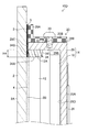
第1実施形態の表示装置10Aを図1〜図3に示す。図1は、第1実施形態の表示装置10Aの平面図であり、図2は、第1実施形態の表示装置10Aの背面図であり、図3は、図2のA−A´に沿う断面図である。すなわち、図3では、ウィンドウガラス2の一方面2Bに液晶パネル12が第1粘着剤4を介して貼付されて構成された表示装置10Aが示されている。なお、図3では、照明部材14を構成するバックライト16を分かり易く説明するために、簡略化して示している。
<Display Device of First Embodiment>
A
図1〜図3に示す第1実施形態の表示装置10Aは、略鉛直方向に沿って配置されるウィンドウガラス2の一方面2Bに、液晶パネル12および照明部材14がこの順に有する表示装置である。液晶パネル12は、第1粘着剤4を介してウィンドウガラス2の一方面2Bに貼合されており、照明部材14は、バックライト16と、バックライト16を収容し枠部28Bおよび底面28Dを有する略凹状のケース28とを有する。照明部材14は、ケース28の枠部28Bの外側面29Aに取り付けられる1以上の取付部材20と、取付部材20をウィンドウガラス2の一方面2Bに貼合する第2粘着剤5とにより、ウィンドウガラス2の一方面2Bに接合されており、ケース28は、ケース28の上側の枠部28Bの内側面29Bが液晶パネル12の少なくとも上側の端面12Aと接している。
The
〈ウィンドウガラス2〉
ウィンドウガラス2は、液晶パネル12および照明部材14を配置する一方面2Bと、他方面2Aとを有する。他方面2Aおよび一方面2Bの向きによって、表示面を自由に変えることができる。例えば、ウィンドウガラス2が構造物の開口部である場合、外側を他方面2Aとすれば、表示面を外側に向けることができる。一方で、内側を他方面2Aとすれば、表示面を構造物の内側に向けることができる。
<
ウィンドウガラス2の形状は、液晶パネル12の面積よりも大きければよい。ウィンドウガラス2の平面形状は、第1粘着剤4によって貼付しようとする矩形の液晶パネル12の画像表示面の面積よりも大きければ特に限定されない。図1において、ウィンドウガラス2の形状は一例としての矩形を示しているが、ウィンドウガラス2は曲線の辺を有してもよく、円形でもよい。ウィンドウガラス2の厚さは、機械的強度、透明性等の観点から、2.0mm〜5.0mm程度が好ましいが、これに限定されるものではない。
The shape of the
〈遮光部3〉
遮光部3は、ウィンドウガラス2の一方面2Bにおいて、取付部材20およびケース28の端面28Cを有する位置に設けられる。例えば、図1の如く、ウィンドウガラス2をウィンドウガラス2の法線方向から見て、矩形のウィンドウガラス2の4辺に沿って枠状に形成される。ここで、ウィンドウガラス2の全領域のうち、遮光部3で囲まれた矩形領域2C(以下、透光部ともいう。)が、液晶パネル12の画像表示面の領域とほぼ一致している。
<
The
遮光部3は、例えば、黒色顔料を含むセラミック塗料を、スクリーン印刷法を用いてウィンドウガラス2の一方面2Bに直接形成できる。また、図8を用いて後述するが、遮光部3を第2透明基板36の一方面36B又は他方面36A上に形成し、第2透明基板36を第1透明基板であるウィンドウガラス2の一方面2Bに第3粘着剤38によって固定した形態でもよい。
The
第1実施形態の表示装置10Aは、遮光部3を有するので、第1粘着剤4によって液晶パネル12をウィンドウガラス2の一方面2Bに貼付した後、ウィンドウガラス2を他方面2A側から見たときに、液晶パネル12の画像表示面の領域の外側領域を遮光部3によって隠すことができる。これにより、ウィンドウガラス2を他方面2A側から見たときに、液晶パネル12に接続されたフレキシブルプリント配線板等の配線部材が、遮光部3によって隠される。また、後述する照明部材14のケース28の枠部28B、およびケース28の枠部28Bに備えられた取付部材20も遮光部3によって隠される。これにより、ウィンドウガラス2を他方面2A側から見たときには、遮光部3によって囲まれた液晶パネル12の画像表示面のみが見える。なお、遮光部3の厚さは、例えば数ミクロンから数百ミクロンである。
Since the
〈第1粘着剤4〉
第1実施形態の表示装置10Aは、ウィンドウガラス2の一方面2Bに液晶パネル12を貼付する第1粘着剤4を有する。この第1粘着剤4により、液晶パネル12は、ウィンドウガラス2に保持される。
<First adhesive 4>
The display device 10 </ b> A of the first embodiment includes a
第1粘着剤4の25℃で1Hzにおけるせん断弾性率は、1×10²Pa〜1×10⁶Paであることが好ましい。せん断弾性率がこの範囲にある第1粘着剤4を使用すれば、液晶パネル12をウィンドウガラス2に充分保持できる。同様の理由で、前記せん断弾性率は、1×10³Pa〜1×10⁵Paであることがより好ましく、1×10³Pa〜1×10⁴Paでることがさらに好ましい。第1粘着剤4の厚さは、0.1〜2.0mm程度が好ましく、0.2〜0.8mm程度がより好ましい。
The shear modulus of the first pressure-
第1粘着剤4の原料としては、光硬化性樹脂組成物が挙げられ、具体的にはアクリル系の樹脂組成物、シリコーン系の樹脂組成物、エポキシ系の樹脂組成物が挙げられる。
As a raw material of the
〈第2粘着剤5〉
第1実施形態の表示装置10Aは、取付部材20をウィンドウガラス2の一方面2Bに貼付する第2粘着剤5を有する。第2粘着剤5は、ウィンドウガラス2の一方面2Bの、遮光部3を有する領域に貼付される。そのため、取付部材20は、遮光部3を有する領域に貼付される。
<
The display device 10 </ b> A of the first embodiment has a
第2粘着剤5は、第1粘着剤4と同一の材料を用いてもよく、異なる材料を用いてもよい。例えば、両面接着テープ(3M社製のアクリルフォーム構造用接合テープVHB(登録商標))を使用できる。
The
〈液晶パネル12〉
液晶パネル12は、液晶ディスプレイ(不図示)から図2に示す照明部材14、駆動回路22、電源回路24および接続コネクタ26等を取り外した主要構成部材である。液晶パネル12の構成は周知であるが、例えば、薄膜トランジスタ(Thin Film Transistor)を備えたTFT素子基板とカラーフィルター(Color Filter)を備えたCF基板との間に液晶を封入し、このTFT素子基板とCF基板とを一対の偏光板によって挟持することにより構成されている。そして、前述の一対の偏光板のうち、ウィンドウガラス2の一方面2Bに対面する偏光板が第1粘着剤4によってウィンドウガラス2の一方面2Bに貼付される。これによって、液晶パネル12がウィンドウガラス2に固定される。液晶パネル12の厚さは、例えば0.2mm〜1.0mmである。
<
The
液晶パネル12の駆動方式は、特に限定されないが、例えば、インプレイン・スイッチング(In-Plane Switching)等の横電界方式が挙げられる。また、実施形態では、液晶パネル12を第1粘着剤4によってウィンドウガラス2の一方面2Bに直接貼付する形態を説明するが、これに限定されるものではない。例えば、ウィンドウガラス2の一方面2Bと液晶パネル12との間に第2透明基板を介在させた形態でもよい。この形態は、図8において後述する。この形態の場合、第3粘着剤38によって第2透明基板36とウィンドウガラス2とが積層されてなる透明部材が、本発明の透明基板に相当する。
The driving method of the
〈照明部材14〉
照明部材14は、ウィンドウガラス2の一方面2Bに配置され、液晶パネル12を照明する板状のバックライト16、およびバックライト16を収容し枠部28Bおよび底面28Dを有し、液晶パネル12を覆う矩形のケース28を含む。このケース28の背面板28Aの所定の位置に駆動回路22、電源回路24および接続コネクタ26等が固定される。
<Lighting
The illuminating
面光源であるバックライト16は、発光ダイオード等の発光素子と、導光板と、必要に応じてプリズムシート、光拡散シート等の1枚又は複数枚の光学フィルムと、ミラーと、を備える。発光素子から射出された光は、導光板に入射して内部を導光する間にミラーで反射し、光学フィルムを介して液晶パネル12に向けて射出される。光学フィルムは、導光板から射出された光の強度を均一化したり、視野角を変更したり、光の利用効率を改善する機能を有する。そのため、光学フィルムと液晶パネル12とは、必要に応じて間隔をおいて配置されている。
The
ケース28は例えば、金属製であり、底面28Dを有する背面板28Aと、背面板28Aに対して略垂直な位置に有する枠部28Bと、を有する。枠部28Bは、背面板28Aの全周縁部に沿って設けられていてもよく、一部が切り欠かれて間欠的に設けられていてもよい。ケース28は、例えば板厚1mmのアルミニウム製板状材を、プレス成型することによって構成されており、軽量化が図られている。
The
図3の如くケース28の枠部28Bの端面28Cがウィンドウガラス2の一方面2Bの遮光部3の領域に設けられている。本実施形態においては、端面28Cは、遮光部3に当接される。そして、ケース28の上側の枠部28Bの内側面29Bと液晶パネル12の上側の端面12Aとが接している。なお、本明細書において、枠部28Bの内側面29Bとは、液晶パネル12の端面12Aに対向する面を指す。上記した構成を有するので、照明部材14は、後述する取付部材20をウィンドウガラス2に貼付する第2粘着剤5および液晶パネル12を貼付する第1粘着剤4の二つの密着力を利用して、ウィンドウガラス2の一方面2Bに接合される。このような構成とすることにより、遮光部3の面積が小さくなることに伴い第2粘着剤5の面積が小さくなる場合、照明部材14が重くなる場合があっても、照明部材14をウィンドウガラス2に対してズレや剥がれ落ちることなく固定できる。
As shown in FIG. 3, the
〈取付部材20〉
照明部材14は、ケース28の枠部28Bの外側面29Aと接合する1以上の取付部材20を有する。取付部材20を利用して、照明部材14がウィンドウガラス2の一方面2Bに固定される。具体的に説明すると、取付部材20の基部20Aを、ウィンドウガラス2の一方面2Bの遮光部3を有する領域に第2粘着剤5によって貼付する。そして、取付部材20とケース28の枠部28Bの外側面29Aとを接合する。これにより、照明部材14が、取付部材20を介してウィンドウガラス2の一方面2Bに接合される。第1実施形態においては、取付部材20としてアングルを使用し、取付部材20と、ケース28の枠部28Bの外側面29Aとをボルト30によって接合している。ボルト30として、日本工業規格(JIS B1176:2006)で規定される、ねじ呼び径がM3である六角穴付きボルトが挙げられる。なお、取付部材20とケース28の枠部28Bの外側面29Aとの接合方法はボルトを用いた方法には限定されない。
<Mounting
The
また、取付部材20は、ケース28の枠部28Bの外側面29Aに配置される。図2に示すように、各辺に1の取付部材20を用いて枠部28Bの周囲に配置することができる。また、図4に示すように、各辺に1以上の取付部材20を配置してもよい。図4の形態では、短片の取付部材20を所定の間隔をもって配置したり、長片の取付部材20を所定の間隔をもって、また、端部同士を突き合わせて配置したりしている。
Further, the
〔第1実施形態の表示装置10Aの組立手順〕
第1実施形態の表示装置10Aは、図3の如く、ウィンドウガラス2の一方面2Bに、第1粘着剤4を介して液晶パネル12の画像表示面を隙間なく貼付し、次いで、照明部材14を液晶パネル12に対して決まった位置に配置して固定することにより製造する。
[Assembly Procedure of
As shown in FIG. 3, the display device 10 </ b> A according to the first embodiment affixes the image display surface of the
照明部材14は、ケース28の枠部28Bの端面28Cを、遮光部3に当接させるとともに、ケース28の上側の枠部28Bの内側面29Bを液晶パネル12の上側の端面12Aに接触させて、照明部材14を液晶パネル12に対して位置決めする。このとき、照明部材14は、液晶パネル12によって鉛直方向に支持される。
The illuminating
次に、取付部材20の基部20Aを第2粘着剤5に接着し、取付部材20の壁部20Bとケース28の枠部28Bの外側面29Aとをボルト30によって締結する。これにより、照明部材14がウィンドウガラス2の一方面2Bに対し、液晶パネル12と取付部材20とによって鉛直方向に支持される。上記の手順によって表示装置10Aが組み立てられる。
Next, the
第1実施形態の表示装置10Aは、ケース28の上側の枠部28Bの内側面29Bと、液晶パネル12の上側の端面12Aとが接している。すなわち、ケース28の上側の枠部28Bの内側面29Bを、液晶パネル12の上側の端面12Aに載置することで、ウィンドウガラス2に照明部材14を支持させる荷重の一部を、液晶パネル12側の第1粘着剤4に持たせている。第1粘着剤4の面積は、第2粘着剤5の面積に対して数倍ある。これにより、第2粘着剤5にかかっていた荷重、つまり、照明部材14を支持する荷重が大幅に小さくなるので、その分だけ第2粘着剤5の接着面積を小さくすることができる。よって、液晶パネル12の画像表示面を囲む遮光部3の面積を小さくすることができるので、従来では実現が困難であったデザインの表示装置10Aを提供できる。
In the display device 10 </ b> A of the first embodiment, the inner side surface 29 </ b> B of the
遮光部3の面積については、遮光部3の幅H1と図9に示した従来の遮光部120の幅H2とを比較すると、幅H1を幅H2に対して55%程度小さくすることができた。例えば、従来では40mm〜45mmの幅H2が必要であったものを、18mm〜20mmの幅H1にすることができた。もちろんであるが、第1実施形態では、その幅H1に対応したサイズの取付部材20が使用されている。
As for the area of the light-shielding
なお、表示装置10Aでは、金属製のケース28の枠部28Bの内側面29Bを、液晶パネル12の端面12Aに直接接触させるため、枠部28Bの内側面29Bを例えばフッ素樹脂でコーティングすることが好ましい。これにより、接触時に端面12Aが破損することを防止することができ、かつ接触させて位置決めする際に、ケース28の枠部28Bの内側面29Bが端面12Aに対して円滑に滑るので、組立性が向上する。
In the
〔第2実施形態の表示装置10B〕
図5は、第2実施形態の表示装置10Bの上部の拡大断面図である。なお、図3に示した第1実施形態の表示装置10Aと同一又は類似の部材については同一の符号を付し、その説明は省略する。
[
FIG. 5 is an enlarged cross-sectional view of the upper portion of the
第2実施形態の表示装置10Bでは、略鉛直方向に沿って配置されるウィンドウガラス2の一方面2Bに、液晶パネル12および照明部材14がこの順に有する表示装置であって、液晶パネル12は、第1粘着剤4を介してウィンドウガラス2の一方面2Bに貼合されている。照明部材14は、バックライト16と、バックライト16を収容し枠部28Bおよび底面28Dを有する略凹状のケース28とを有する。また、照明部材14は、ケース28の枠部28Bの外側面29Aに取り付けられる1以上の取付部材32と、取付部材32をウィンドウガラス2の一方面2Bに貼合する第2粘着剤5とにより、ウィンドウガラス2の一方面2Bに接合されており、取付部材32は、液晶パネル12の少なくとも上側の端面12Aと接している。具体的には、上側に位置する取付部材20の内面32Dが液晶パネル12の上側の端面12Aと接している。なお、図5では、取付部材32の内面32Dのみが液晶パネル12の端面12Aと接しているが、取付部材32の内面32Dおよびケース28の上側の枠部28Bの内側面29Bが液晶パネル12の端面12Aと接していてもよい。なお、本明細書において、取付部材32の内面32Dとは、取付部材32の液晶パネル12の端面12Aに対向する面を指す。
In the
具体的に説明すると、本実施形態における取付部材32は基部32A、壁部32B、フランジ部32Cおよび内面32Dからなる断面T字状に構成される。基部32Aとフランジ部32Cとが第2粘着剤5によってウィンドウガラス2の一方面2Bに固定され、この部分が遮光部3によって隠される。また、取付部材32は、フランジ部32Cの下部に形成された内面32Dを液晶パネル12の上側の端面12Aに接触させた状態でウィンドウガラス2の一方面2Bに第2粘着剤5によって接着される。そして、壁部32Bにケース28の枠部28Bがボルト30によって固定される。
More specifically, the
第2実施形態の表示装置10Bは、上記の通り、少なくとも取付部材32の内面32Dと液晶パネル12の上側の端面12Aとを接触させることで、照明部材14をウィンドウガラス2に支持する荷重の一部を、液晶パネル12側の第1粘着剤4に持たせている。これにより、第2粘着剤5にかかっていた荷重、つまり、照明部材14を支持する荷重が小さくなるので、第2粘着剤5の接着面積を小さくすることができる。よって、遮光部3の面積を小さくすることができるので、従来では実現が困難であったデザインの表示装置10Bを提供できる。
As described above, the display device 10 </ b> B according to the second embodiment is a load that supports the
ここで、図5の表示装置10Bは、図3の表示装置10Aと比較して、遮光部3の幅は、ケース28の枠部28Bから液晶パネル12の端面12Aに当接する長さ分の幅H3だけ大きくなる。しかし、この幅H3は1mm程度なので、本発明による遮光部3の幅の55%程度の減少分と比較すれば影響を与えない。この観点から、幅H3は、0以上であって、遮光部3の幅の減少分に影響を与えない幅に設定することが好ましい。
Here, in the
なお、表示装置10Bでは、取付部材32の内面32Dが液晶パネル12の端面12Aに直接接触するため、取付部材32を樹脂製としたり、取付部材32が金属製の場合には内面32Dにフッ素樹脂をコーティングしたりすることが好ましい。これにより、取付部材32の内面32Dが液晶パネル12の端面12Aに接触した時に端面12Aが破損することを防止することができる。
In the
〔第3実施形態の表示装置10C〕
図6は、第3実施形態の表示装置10Cの上部の拡大断面図である。なお、図4に示した第1実施形態の表示装置10Aと同一又は類似の部材については同一の符号を付し、その説明は省略する。
[
FIG. 6 is an enlarged cross-sectional view of the upper part of the
第3実施形態の表示装置10Cでは、取付部材20と液晶パネル12の上側の端面12Aとを、中間支持部材34を介して接触させた形態である。第3の実施形態においては、このような構成により、照明部材14をウィンドウガラス2に支持する荷重の一部を、液晶パネル12側の第1粘着剤4に持たせている。
In the display device 10 </ b> C of the third embodiment, the mounting
具体的に説明すると、中間支持部材34は、液晶パネル12の上側の端面12Aに沿って連続的又は間欠的に配置されている。中間支持部材34の下面34Aを液晶パネル12の上側の端面12Aに接触させ、中間支持部材34の基面34Bを第2粘着剤5に接着させ、基面34Bに対向する位置決め面34Cに、ケース28の枠部28Bの端面28Cを当接し、照明部材14を液晶パネル12に対して位置決めしている。また、取付部材20の取り付け、および取付部材20とケース28の固定は表示装置10Aと同様である。
Specifically, the
第3実施形態の表示装置10Cは、上記の通り、取付部材20と液晶パネル12の上側の端面12Aとを、中間支持部材34を介して接触させることで、照明部材14をウィンドウガラス2に支持する荷重の一部を、液晶パネル12側の第1粘着剤4に持たせている。これにより、第2粘着剤5にかかっていた荷重、つまり、照明部材14を支持する荷重が小さくなるので、第2粘着剤5の接着面積を小さくすることができる。よって、第2粘着剤5を隠す遮光部3の面積を小さくすることができるので、従来では実現が困難であったデザインの表示装置10Cを提供できる。
As described above, the display device 10 </ b> C of the third embodiment supports the
〔第4実施形態の表示装置10D〕
図7は、第4実施形態の表示装置10Dの上部の拡大断面図である。なお、図6に示した第3実施形態の表示装置10Cと同一又は類似の部材については同一の符号を付し、その説明は省略する。
[
FIG. 7 is an enlarged cross-sectional view of the upper part of the
第4実施形態の表示装置10Dは、ケース28の上側の枠部28Bの内側面29Bと液晶パネル12の上側の端面12Aとを、中間支持部材34を介して接触させた形態である。第4実施形態の表示装置Dも同様に、照明部材14をウィンドウガラス2に支持する荷重の一部を、液晶パネル12側の第1粘着剤4に持たせることができるので、第2粘着剤5の接着面積を小さくすることができる。
The display device 10 </ b> D of the fourth embodiment has a configuration in which the inner side surface 29 </ b> B of the
ここで、図6、図7の表示装置10C、10Dは、図3の表示装置10Aと比較して、遮光部3の幅は、ケース28の枠部28Bから液晶パネル12の端面12Aに当接する長さ分の幅H4だけ大きくなる。しかし、この幅H4は、数mm程度なので、本発明による遮光部3の幅の55%程度の減少分と比較すれば影響を与えない。この観点から、幅H4は、0以上であって、遮光部3の幅の減少分に影響を与えない幅に設定することが好ましい。
Here, in the
なお、表示装置10C、10Dでは、中間支持部材34の下面34Aが液晶パネル12の端面12Aに直接接触するため、中間支持部材34を樹脂製としたり、中間支持部材34が金属製の場合には下面34Aにフッ素樹脂をコーティングしたりすることが好ましい。これにより、中間支持部材34の下面34Aが液晶パネル12の端面12Aに接触した時に端面12Aが破損することを防止することができる。
In the
さらに、照明部材の荷重がかかっても、中間部材の変形が抑えられる点で、中間支持部材34のヤング率は0.5GPa〜3GPaが好ましい。中間支持部材34が変形し、バックライトの位置がずれると、表示画像の品質が低下するおそれがあるので、その問題を解消するためである。
Furthermore, the Young's modulus of the
〔第5実施形態の表示装置10E〕
図8は、第5実施形態の表示装置10Eの上部の拡大断面図である。なお、図3に示した第1実施形態の表示装置10Aと同一又は類似の部材については同一の符号を付し、その説明は省略する。
[
FIG. 8 is an enlarged cross-sectional view of the upper part of the
第5実施形態の表示装置10Eでは、透明基板として、第1透明基板であるウィンドウガラス2と第2透明基板36とを有し、ウィンドウガラス2の一方面2Bと第2透明基板36の他方面36Aが第3粘着剤38によって貼付されて透明基板を構成している。そして、第2透明基板36の一方面36B側に液晶パネル12、第1粘着剤4、照明部材14、取付部材20、第2粘着剤5および遮光部3が備えられている。なお、図8においては、遮光部3は、第2透明基板の一方面36B側に設けているが、他方面36A側に設けてもよい。遮光部3を他方面36Aに設ける場合には、遮光部3を有する領域と重複する位置に取付部材20およびケース28の端面28Cを設ける。
The
第5実施形態の表示装置10Eは、第1透明基板であるウィンドウガラス2と第2透明基板36とからなる透明基板であっても、第1実施形態の表示装置10Aと同様の効果、すなわち、第2粘着剤5の接着面積を小さくすることができる。よって、第2粘着剤5を隠す遮光部3の面積を小さくすることができるので、従来では実現が困難であったデザインの表示装置10Eを提供できる。なお、第3粘着剤38については、第1粘着剤4と同一の粘着剤を使用することができる。これにより、第2透明基板36がウィンドウガラス2に確実に固定される。
Even if the
本発明の実施形態として表示装置10A、10B、10C、10D、10Eについて説明したが、本発明の思想は、従来では照明部材の荷重を第2粘着剤のみで支持していたものを、第1粘着剤によって照明部材の荷重の一部を負担させることで遮光部の面積を小さくすることにある。この思想を達成するために、既存の部品(ケース28の枠部28Bおよび取付部材32)を用いる第1、第2および第5実施形態を説明し、他の部品(中間支持部材34)を用いる第3および第4実施形態を説明した。しかしながら、本発明の思想は前述通りなので、第1乃至第5実施形態に限定されず、本発明の思想を達成することが可能な形態であれば適用することができる。
Although the
2…ウィンドウガラス、2A…他方面、2B…一方面、3…遮光部、4…第1粘着剤、5…第2粘着剤、6…保護フィルム、10A…第1実施形態の表示装置、10B…第2実施形態の表示装置、10C…第3実施形態の表示装置、10D…第4実施形態の表示装置、10E…第5実施形態の表示装置、12…液晶パネル、12A…端面、14…照明部材、20…取付部材、20A…基部、20B…壁部、22…駆動回路、24…電源回路、26…接続コネクタ、28…ケース、28A…背面板、28B…枠部、28C…端面、28D…底面、29A…外側面、29B…内側面、30…ボルト、32…取付部材、32A…基部、32B…壁部、32C…フランジ部、32D…内面、34…中間支持部材、34A…下面、34B…基面、34C…位置決め面、36…第2透明基板、38…第3粘着剤
DESCRIPTION OF
Claims (6)
前記液晶パネルは、第1粘着剤を介して前記透明基板の一方面に貼合されており、
前記照明部材は、バックライトと、前記バックライトを収容し枠部および底面を有する略凹状のケースとを有し、
前記照明部材は、前記ケースの枠部の外側面に取り付けられる1以上の取付部材と、前記取付部材を前記透明基板の一方面に貼合する第2粘着剤とにより、前記透明基板の一方面に接合されており、
前記ケースは、前記ケースの上側の枠部の内側面が前記液晶パネルの少なくとも上側の端面と接している表示装置。 A display device having a liquid crystal panel and a lighting member in this order on one surface of a transparent substrate arranged along a substantially vertical direction,
The liquid crystal panel is bonded to one surface of the transparent substrate via a first adhesive,
The illumination member includes a backlight, and a substantially concave case that houses the backlight and has a frame portion and a bottom surface,
The lighting member includes one or more mounting members that are attached to the outer surface of the frame portion of the case, and a second adhesive that bonds the mounting member to one surface of the transparent substrate. Are joined to
The case is a display device in which an inner side surface of an upper frame portion of the case is in contact with at least an upper end surface of the liquid crystal panel.
前記液晶パネルは、第1粘着剤を介して前記透明基板の一方面に貼合されており、
前記照明部材は、バックライトと、前記バックライトを収容し枠部および底面を有する略凹状のケースとを有し、
前記照明部材は、前記ケースの枠部の外側面に取り付けられる1以上の取付部材と、前記取付部材を前記透明基板の一方面に貼合する第2粘着剤とにより、前記透明基板の一方面に接合されており、
前記取付部材は、前記液晶パネルの少なくとも上側の端面と接している表示装置。 A display device having a liquid crystal panel and a lighting member in this order on one surface of a transparent substrate arranged along a substantially vertical direction,
The liquid crystal panel is bonded to one surface of the transparent substrate via a first adhesive,
The illumination member includes a backlight, and a substantially concave case that houses the backlight and has a frame portion and a bottom surface,
The lighting member includes one or more mounting members that are attached to the outer surface of the frame portion of the case, and a second adhesive that bonds the mounting member to one surface of the transparent substrate. Are joined to
The display device, wherein the attachment member is in contact with at least an upper end surface of the liquid crystal panel.
前記第1透明基板の一方面と前記第2透明基板の他方面とが第3粘着剤によって貼付され、
前記第2透明基板の一方面側に前記液晶パネル、前記第1粘着剤、前記照明部材、前記取付部材、前記第2粘着剤および遮光部が備えられる請求項1〜5のいずれかに記載の表示装置。 The transparent substrate has a first transparent substrate and a second transparent substrate,
The one surface of the first transparent substrate and the other surface of the second transparent substrate are affixed by a third adhesive,
The said liquid crystal panel, the said 1st adhesive, the said illumination member, the said attachment member, the said 2nd adhesive, and the light-shielding part are provided in the one surface side of the said 2nd transparent substrate. Display device.
Priority Applications (1)
| Application Number | Priority Date | Filing Date | Title |
|---|---|---|---|
| JP2016123795A JP2017227767A (en) | 2016-06-22 | 2016-06-22 | Display device |
Applications Claiming Priority (1)
| Application Number | Priority Date | Filing Date | Title |
|---|---|---|---|
| JP2016123795A JP2017227767A (en) | 2016-06-22 | 2016-06-22 | Display device |
Publications (1)
| Publication Number | Publication Date |
|---|---|
| JP2017227767A true JP2017227767A (en) | 2017-12-28 |
Family
ID=60891649
Family Applications (1)
| Application Number | Title | Priority Date | Filing Date |
|---|---|---|---|
| JP2016123795A Pending JP2017227767A (en) | 2016-06-22 | 2016-06-22 | Display device |
Country Status (1)
| Country | Link |
|---|---|
| JP (1) | JP2017227767A (en) |
Cited By (1)
| Publication number | Priority date | Publication date | Assignee | Title |
|---|---|---|---|---|
| JP2021189328A (en) * | 2020-06-01 | 2021-12-13 | 三菱電機株式会社 | Display device |
Citations (4)
| Publication number | Priority date | Publication date | Assignee | Title |
|---|---|---|---|---|
| JP2006065008A (en) * | 2004-08-27 | 2006-03-09 | Casio Comput Co Ltd | Holding tool of panel element |
| JP2006235082A (en) * | 2005-02-23 | 2006-09-07 | Sony Corp | Liquid crystal display device |
| JP2014029448A (en) * | 2012-07-31 | 2014-02-13 | Toshiba Corp | Liquid crystal module and liquid crystal display device |
| WO2015072380A1 (en) * | 2013-11-15 | 2015-05-21 | 旭硝子株式会社 | Transparent face plate with adhesive layer and display device |
-
2016
- 2016-06-22 JP JP2016123795A patent/JP2017227767A/en active Pending
Patent Citations (4)
| Publication number | Priority date | Publication date | Assignee | Title |
|---|---|---|---|---|
| JP2006065008A (en) * | 2004-08-27 | 2006-03-09 | Casio Comput Co Ltd | Holding tool of panel element |
| JP2006235082A (en) * | 2005-02-23 | 2006-09-07 | Sony Corp | Liquid crystal display device |
| JP2014029448A (en) * | 2012-07-31 | 2014-02-13 | Toshiba Corp | Liquid crystal module and liquid crystal display device |
| WO2015072380A1 (en) * | 2013-11-15 | 2015-05-21 | 旭硝子株式会社 | Transparent face plate with adhesive layer and display device |
Cited By (2)
| Publication number | Priority date | Publication date | Assignee | Title |
|---|---|---|---|---|
| JP2021189328A (en) * | 2020-06-01 | 2021-12-13 | 三菱電機株式会社 | Display device |
| JP7179034B2 (en) | 2020-06-01 | 2022-11-28 | 三菱電機株式会社 | Display device |
Similar Documents
| Publication | Publication Date | Title |
|---|---|---|
| US9904003B2 (en) | Backlight module | |
| JP4575486B2 (en) | Display device | |
| US9341875B2 (en) | Electronic device | |
| JP5261082B2 (en) | Electro-optical device and electronic apparatus | |
| KR20080082462A (en) | Display device | |
| JP5126033B2 (en) | Display device | |
| US9274362B2 (en) | Curved liquid crystal display device | |
| WO2017190380A1 (en) | Liquid crystal display apparatus having adhesive-free frame and packaging method thereof | |
| CN105938272B (en) | Ultrathin backlight module and touch all-in-one machine based on same | |
| US20180107062A1 (en) | Backlight module and assembly method thereof | |
| JP2010027333A (en) | Backlight unit and its assembly method | |
| TW201335677A (en) | Backlight module and display device using the same | |
| JP5646744B2 (en) | Display module and display device including the module | |
| US20170045671A1 (en) | Backlight modules and liquid crystal devices (lcds) | |
| JP2017120310A (en) | Display device, adhesive sheet used for display device, and method for manufacturing the display device | |
| JP5287415B2 (en) | Backlit LCD module | |
| US8947615B2 (en) | Frameless liquid crystal display device | |
| CN100487536C (en) | Liquid crystal display device | |
| GB2546054A (en) | Display | |
| JP2017227767A (en) | Display device | |
| JP5389712B2 (en) | Liquid crystal display device and electronic apparatus including the same | |
| US9323086B2 (en) | Curved liquid crystal display device | |
| JP2015094842A (en) | Display device | |
| US10031280B2 (en) | Display device | |
| WO2011152158A1 (en) | Liquid crystal display device and planar light source device provided to liquid crystal display device |
Legal Events
| Date | Code | Title | Description |
|---|---|---|---|
| A621 | Written request for application examination |
Free format text: JAPANESE INTERMEDIATE CODE: A621 Effective date: 20190129 |
|
| A977 | Report on retrieval |
Free format text: JAPANESE INTERMEDIATE CODE: A971007 Effective date: 20191129 |
|
| A131 | Notification of reasons for refusal |
Free format text: JAPANESE INTERMEDIATE CODE: A131 Effective date: 20191210 |
|
| A521 | Request for written amendment filed |
Free format text: JAPANESE INTERMEDIATE CODE: A523 Effective date: 20200127 |
|
| A02 | Decision of refusal |
Free format text: JAPANESE INTERMEDIATE CODE: A02 Effective date: 20200417 |