JP2017227422A - Manifold for gas supply - Google Patents
Manifold for gas supply Download PDFInfo
- Publication number
- JP2017227422A JP2017227422A JP2016125930A JP2016125930A JP2017227422A JP 2017227422 A JP2017227422 A JP 2017227422A JP 2016125930 A JP2016125930 A JP 2016125930A JP 2016125930 A JP2016125930 A JP 2016125930A JP 2017227422 A JP2017227422 A JP 2017227422A
- Authority
- JP
- Japan
- Prior art keywords
- gas supply
- body member
- main body
- supply manifold
- lid member
- Prior art date
- Legal status (The legal status is an assumption and is not a legal conclusion. Google has not performed a legal analysis and makes no representation as to the accuracy of the status listed.)
- Granted
Links
Images


Classifications
-
- F—MECHANICAL ENGINEERING; LIGHTING; HEATING; WEAPONS; BLASTING
- F23—COMBUSTION APPARATUS; COMBUSTION PROCESSES
- F23D—BURNERS
- F23D14/00—Burners for combustion of a gas, e.g. of a gas stored under pressure as a liquid
- F23D14/02—Premix gas burners, i.e. in which gaseous fuel is mixed with combustion air upstream of the combustion zone
- F23D14/04—Premix gas burners, i.e. in which gaseous fuel is mixed with combustion air upstream of the combustion zone induction type, e.g. Bunsen burner
- F23D14/06—Premix gas burners, i.e. in which gaseous fuel is mixed with combustion air upstream of the combustion zone induction type, e.g. Bunsen burner with radial outlets at the burner head
-
- F—MECHANICAL ENGINEERING; LIGHTING; HEATING; WEAPONS; BLASTING
- F23—COMBUSTION APPARATUS; COMBUSTION PROCESSES
- F23D—BURNERS
- F23D14/00—Burners for combustion of a gas, e.g. of a gas stored under pressure as a liquid
- F23D14/02—Premix gas burners, i.e. in which gaseous fuel is mixed with combustion air upstream of the combustion zone
- F23D14/04—Premix gas burners, i.e. in which gaseous fuel is mixed with combustion air upstream of the combustion zone induction type, e.g. Bunsen burner
Abstract
Description
本発明は、ガス燃焼装置の構成要素として用いられるガス供給用マニホールドに関する。 The present invention relates to a gas supply manifold used as a component of a gas combustion apparatus.
ガス給湯装置に具備されるガス燃焼装置は、燃料ガスを燃焼させるための複数のバーナヘッド(燃焼管)が、バーナケース内に並べて配され、かつ前記複数のバーナヘッドには、ガス供給用マニホールドから燃料ガスが供給される構成とされているのが一般的である。
ここで、ガス供給用マニホールドとしては、たとえば特許文献1,2に記載のものがある。
これらの文献に記載されたガス供給用マニホールドは、複数のガス噴出ノズルが設けられた本体部材と、この本体部材にシール用パッキンを介して重ね合わされる蓋部材とを備えている。蓋部材は、本体部材との間にガス供給流路を形成するための部材であり、本体部材に対し、たとえばビス止めによる締結が図られている。蓋部材および本体部材は、たとえば金属板にプレス加工を施すなどして形成されている。
このような構成によれば、ガス供給用マニホールドの部品総数を少なくして製造コストの低減化を図ることが可能である。また、全体の薄型化や軽量化も図ることが可能である。
A gas combustion apparatus provided in a gas hot water supply device includes a plurality of burner heads (combustion pipes) for burning fuel gas arranged side by side in a burner case, and the plurality of burner heads include a gas supply manifold. In general, the fuel gas is supplied from above.
Here, as a manifold for gas supply, there exist a thing of
The gas supply manifold described in these documents includes a main body member provided with a plurality of gas ejection nozzles, and a lid member that is overlapped with the main body member via a seal packing. The lid member is a member for forming a gas supply channel between itself and the main body member, and is fastened to the main body member by, for example, screwing. The lid member and the main body member are formed by, for example, pressing a metal plate.
According to such a configuration, it is possible to reduce the manufacturing cost by reducing the total number of parts of the gas supply manifold. Further, it is possible to reduce the overall thickness and weight.
しかしながら、前記従来技術においては、次に述べるように、改善すべき余地がある。 However, the prior art has room for improvement as described below.
すなわち、ガス供給用マニホールドについては、その製造コストを従来よりもさらに低減し、また全体の軽量化なども促進することが望まれる。そのための一手段として、蓋部材の厚み(板厚)を薄くすることが考えられる。ところが、蓋部材の厚みをただ単に薄くしただけでは、蓋部材が歪み易くなり、反りなどの変形を生じる虞がある。蓋部材のそのような変形は、蓋部材と本体部材との相互間に形成されているガス供給流路内の燃料ガスが外部に漏出する要因となるため、これを適切に防止する必要がある。
なお、蓋部材の反り変形などを抑制する手段としては、たとえば本体部材に対する蓋部材のビス止め箇所の数を多くすることが考えられる。ただし、これでは、ビス止め作業が煩雑となり、製造コストが却って高くなる。また、ビス止め箇所の数を多くしたとしても、それだけでは蓋部材の反り変形などを十分に抑制することは難しい。
That is, it is desired to reduce the manufacturing cost of the gas supply manifold further than before and to promote the weight reduction of the whole. As one means for that, it is conceivable to reduce the thickness (plate thickness) of the lid member. However, simply reducing the thickness of the lid member tends to cause distortion of the lid member, which may cause deformation such as warpage. Such a deformation of the lid member causes the fuel gas in the gas supply flow path formed between the lid member and the main body member to leak to the outside, and it is necessary to appropriately prevent this. .
As a means for suppressing warp deformation of the lid member, for example, it is conceivable to increase the number of screwing portions of the lid member with respect to the main body member. However, this makes the screwing operation complicated, and the manufacturing cost increases. Even if the number of screwing points is increased, it is difficult to sufficiently suppress warping deformation of the lid member.
本発明は、前記したような事情のもとで考え出されたものであり、蓋部材に大きな歪みが生じるような不具合を発生させることなく、蓋部材の薄肉化を図り、軽量化や製造コストの低減化などを適切に図ることが可能なガス供給用マニホールドを提供することを、その課題としている。 The present invention has been conceived under the circumstances as described above, and it is possible to reduce the thickness of the lid member and reduce the weight and the manufacturing cost without causing a problem that a large distortion occurs in the lid member. An object of the present invention is to provide a gas supply manifold that can appropriately reduce the amount of gas.
上記の課題を解決するため、本発明では、次の技術的手段を講じている。 In order to solve the above problems, the present invention takes the following technical means.
本発明により提供されるガス供給用マニホールドは、複数のガス噴出ノズルが設けられている本体部材と、この本体部材の片面に重ねられ、かつ前記本体部材に連結されている蓋部材と、を備えており、前記蓋部材と前記本体部材との間には、前記複数のガス噴出ノズルに連通するガス供給流路が形成されている、ガス供給用マニホールドであって、前記蓋部材は、前記本体部材との重ね合わせ方向において、前記本体部材とは反対側に屈曲して起立した屈曲起立壁部を備え、かつこの屈曲起立壁部は、前記蓋部材と前記本体部材との重ね合わせ方向視において、前記ガス供給流路およびその周辺領域の全周を囲むループ状に形成されていることを特徴としている。 A gas supply manifold provided by the present invention includes a main body member provided with a plurality of gas ejection nozzles, and a lid member which is overlapped on one side of the main body member and connected to the main body member. A gas supply manifold is formed between the lid member and the main body member so as to communicate with the plurality of gas ejection nozzles, and the lid member includes the main body A bending upright wall portion that is bent and raised in a direction opposite to the main body member in the overlapping direction with the member, and the bent upright wall portion is viewed in the overlapping direction of the lid member and the main body member. The gas supply channel and the surrounding region are formed in a loop shape surrounding the entire periphery.
このような構成によれば、次のような効果が得られる。
すなわち、蓋部材と本体部材との重ね合わせ方向視においてループ状に形成されている屈曲起立壁部は、蓋部材のガス供給流路形成領域およびその周辺領域の強度を大きく向上させる。このため、蓋部材の厚みを従来よりも薄くした場合であっても、蓋部材のガス供給流路形成領域およびその周辺領域に歪みを生じ難くし、本体部材との間でガス供給流路からのガス漏れの要因となる隙間を生じないようにすることが可能である。ガス漏れ防止策として、蓋部材と本体部材とのビス止め箇所などの数をかなり多くするといった必要もなくすことが可能である。このようなことから、本発明によれば、蓋部材の薄肉化を適切に図り、ガス供給用マニホールド全体の軽量化や製造コストの低減化などを好適に図ることが可能である。
According to such a configuration, the following effects can be obtained.
That is, the bent upright wall portion formed in a loop shape when viewed from the overlapping direction of the lid member and the main body member greatly enhances the strength of the gas supply flow path formation region of the lid member and its peripheral region. For this reason, even when the thickness of the lid member is thinner than the conventional one, the gas supply flow path formation region of the lid member and its peripheral region are less likely to be distorted and the It is possible to prevent a gap that causes gas leakage. As a measure for preventing gas leakage, it is possible to eliminate the necessity of considerably increasing the number of screwing points between the lid member and the main body member. For this reason, according to the present invention, it is possible to appropriately reduce the thickness of the lid member and to suitably reduce the weight of the entire gas supply manifold, reduce the manufacturing cost, and the like.
本発明において、好ましくは、前記重ね合わせ方向視において、前記屈曲起立壁部の略全周域は、前記本体部材に重なった配置に形成されている。 In the present invention, preferably, when viewed in the overlapping direction, substantially the entire peripheral area of the bent upright wall portion is formed so as to overlap the main body member.
このような構成によれば、次のような効果が得られる。
すなわち、図8などを参照して後述する内容からも理解されるように、たとえば屈曲起立壁部の多くの部分が、本体部材に重なった配置にはなく、本体部材からはみ出した配置に設けられているような場合と比較すると、前記構成によれば、蓋部材のガス供給流路の形成領域およびその周辺領域の強度をより向上させることが可能である。したがって、それらの領域の歪みなどを一層効果的に防止することができる。
According to such a configuration, the following effects can be obtained.
That is, as will be understood from the contents described later with reference to FIG. 8 and the like, for example, many portions of the bent upright wall portion are not disposed so as to overlap the main body member but are disposed so as to protrude from the main body member. Compared with the case where it is, according to the said structure, it is possible to improve the intensity | strength of the formation area of the gas supply flow path of a cover member, and its peripheral region more. Therefore, distortion of those regions can be more effectively prevented.
本発明において、好ましくは、前記蓋部材と前記本体部材との相互間に介装されるシール用のパッキンを、備えており、前記蓋部材には、前記パッキンに設けられている孔部に挿通する位置決め用凸部が形成されており、前記本体部材には、前記位置決め用凸部の先端部が進入するように前記位置決め用凸部の突出方向に窪んだ非貫通孔状の凹部が設けられている。 In the present invention, preferably, a sealing packing interposed between the lid member and the main body member is provided, and the lid member is inserted into a hole provided in the packing. A positioning projection is formed, and the main body member is provided with a non-through-hole-shaped recess that is recessed in the protruding direction of the positioning projection so that the tip of the positioning projection enters. ing.
このような構成によれば、前記位置決め用凸部を利用してシール用のパッキンの位置決めを適切に図ることが可能である。また、前記位置決め用凸部の先端部は、本体部材に設けられた凹部に進入させることができるため、前記位置決め用凸部の突出寸法を、シール用のパッキンの厚みよりも大きくすることができる。したがって、ガス供給用マニホールドの組み立て作業時において、シール用のパッキンの孔部から位置決め用凸部が容易に抜けないようにすることもできる。さらに、本体部材に設けられた凹部は、非貫通孔状であるため、この部分から外部にガス漏れを生じないようにすることが可能である。 According to such a configuration, it is possible to appropriately position the seal packing by using the positioning convex portion. Moreover, since the front-end | tip part of the said convex part for positioning can be made to enter into the recessed part provided in the main body member, the protrusion dimension of the said convex part for positioning can be made larger than the thickness of the packing for sealing. . Therefore, it is possible to prevent the positioning convex portion from being easily removed from the hole portion of the seal packing during the assembly operation of the gas supply manifold. Furthermore, since the recessed part provided in the main body member is a non-through-hole shape, it is possible to prevent a gas leak from this part outside.
本発明において、好ましくは、前記蓋部材には、前記屈曲起立壁部の先端部に繋がって屈曲し、かつ前記重ね合わせ方向視において、前記本体部材の外方にはみ出したフランジ部が設けられており、このフランジ部は、所望の取付け対象部位への取付け部として用いられるように構成されている。 In the present invention, preferably, the lid member is provided with a flange portion that is connected to a distal end portion of the bent upright wall portion and is bent outward from the main body member when viewed in the overlapping direction. And this flange part is comprised so that it may be used as an attachment part to a desired attachment object site | part.
このような構成によれば、フランジ部を利用することにより、ガス供給用マニホールドを所望の取付け対象部位に適切に取付けることが可能となる。このため、蓋部材にループ状の屈曲起立壁部を設けたことに起因してガス供給用マニホールドの取付けが困難になるといった不具合を生じないようにすることができる。屈曲起立壁部は、フランジ部を補強する役割も果たすため、フランジ部の強度も適切に確保される。 According to such a configuration, it is possible to appropriately attach the gas supply manifold to a desired attachment target site by using the flange portion. For this reason, it is possible to prevent a problem that it is difficult to attach the gas supply manifold due to the provision of the looped bent upright wall portion on the lid member. Since the bent upright wall portion also serves to reinforce the flange portion, the strength of the flange portion is appropriately ensured.
本発明において、好ましくは、前記フランジ部は、前記本体部材の起立姿勢状態において、前記本体部材の上側および左右両側にはみ出すように設けられており、このガス供給用マニホールドを前記取付け対象部位に取付ける際には、シール用のループ状パッキンの一部分が、前記本体部材の前面側のうち、前記複数のガス噴出ノズルの下側に位置して左右横幅方向に延び、かつ前記ループ状パッキンの他の部分が、前記フランジ部の前面側に位置するように設定される構成とされている。 In the present invention, preferably, the flange portion is provided so as to protrude from the upper side and the left and right sides of the main body member in the standing posture state of the main body member, and the gas supply manifold is attached to the attachment target site. In this case, a part of the seal-like loop packing is located on the lower side of the plurality of gas ejection nozzles on the front surface side of the main body member and extends in the lateral width direction. The portion is set to be positioned on the front side of the flange portion.
このような構成によれば、ガス供給用マニホールドを取付け対象部位に取付ける場合に、フランジ部と取付け対象部位との間に、シール用のループ状パッキンを適切に介在させ、複数のガス噴出ノズルから噴出されるガスが外部に漏れを生じないように設定することが可能である。 According to such a configuration, when the gas supply manifold is attached to the attachment target portion, the seal loop packing is appropriately interposed between the flange portion and the attachment target portion, and the plurality of gas ejection nozzles are arranged. It is possible to set so that the gas to be ejected does not leak outside.
本発明のその他の特徴および利点は、添付図面を参照して以下に行なう発明の実施の形態の説明から、より明らかになるであろう。 Other features and advantages of the present invention will become more apparent from the following description of embodiments of the present invention with reference to the accompanying drawings.
以下、本発明の好ましい実施の形態について、図面を参照して具体的に説明する。
図面には、矢印Frが適宜示されており、この方向を前方として説明する。
Hereinafter, preferred embodiments of the present invention will be specifically described with reference to the drawings.
In the drawing, an arrow Fr is appropriately shown, and this direction will be described as the front.
図1および図2に示すガス供給用マニホールドAは、ガス給湯装置のガス燃焼装置を構成する部品の1つであり、たとえば図6に示すように、燃焼装置のバーナケース90内に収容された複数のバーナヘッド(燃焼管)91に燃料ガスを供給するためのものである。バーナケース90やバーナヘッド91の基本的な構成は、たとえば特許文献1に記載されたものと同様である。
The gas supply manifold A shown in FIGS. 1 and 2 is one of the components constituting the gas combustion apparatus of the gas water heater, and is accommodated in the
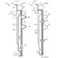
図1および図2において、ガス供給用マニホールドAは、本体部材2、この本体部材2の裏面側に重ねられた蓋部材1、およびこれら本体部材2と蓋部材1との間に介装されたシール用のパッキン3を備えている。本体部材2および蓋部材1は、いずれも金属製プレ
ートにプレス加工を施すことにより形成されたものである。
In FIG. 1 and FIG. 2, the gas supply manifold A is interposed between the
本体部材2は、その上部寄り領域に本体部材2の前方に向けて突出する複数のガス噴出ノズル25が設けられたいわゆるノズルプレートである。本体部材2と蓋部材1との間には、複数のガス噴出ノズル25に連通する複数のガス供給流路29が形成されており、これら複数のガス供給流路29内には、本体部材2の下部領域に設けられた複数の開口部26から燃料ガスを流入させることが可能である。複数のガス供給流路29を形成するための手段として、蓋部材1には、本体部材2とは離間する方向に膨出して背面視筋状をなす複数の膨出部18が形成されている。各膨出部18の内側部分が、ガス供給流路29である。
The
蓋部材1は、屈曲起立壁部11(11a,11b)、フランジ部12、およびシール用のパッキン3の位置決めを図るための左右一対の位置決め用凸部13を有している(図5も参照)。
The
屈曲起立壁部11は、蓋部材1のうち、複数のガス供給流路29の形成領域の周辺領域から蓋部材1の背面側に屈曲して起立した部分であり、蓋部材1の前後方向視において、複数のガス供給流路29およびその周辺領域の全周を囲むループ状である。ここで「前後方向視」は、本発明でいう蓋部材と本体部材との重ね合わせ方向視に相当する。屈曲起立壁部11は、より具体的には、前後方向視における本体部材2の外形の輪郭と略同様な形態のループ状である。屈曲起立壁部11は、蓋部材1の上部寄りに位置し、かつフランジ部12が先端部に連設されている上側屈曲起立壁部11a(11)と、この上側屈曲起立壁部11aに一体的に繋がり、かつ蓋部材1の下部寄りに位置する下側屈曲起立壁部11b(11)とに区分することができる。本実施形態においては、図2(b)に示すように、上側および下側の屈曲起立壁部11a,11bの起立高さHa,Hbは、Ha>Hbの関係とされているが、本発明はこれに限定されず、それらの高さHa,Hbは、同一、非同一のいずれであってもよい。
The bent
ループ状の屈曲起立壁部11の略全周域は、ガス供給用マニホールドAの前後方向視において、本体部材2に重なった配置に形成されている。このことにより、蓋部材1のうち、ループ状の屈曲起立壁部11によって囲まれた領域の略全体は、本体部材2に重なった重なり領域10となっている。蓋部材1の重なり領域10は、複数のビス50を用いて本体部材2にビス止めされている。
The substantially entire circumferential area of the loop-like bent
一対の位置決め用凸部13は、蓋部材1の重なり領域10の左右両端部またはその近傍に設けられている。この位置決め用凸部13は、蓋部材1に孔部13aを形成してその隣接箇所を起立させる加工(切り起こし加工)を施すことにより形成されたものであり、前方を向いて突出している。ガス供給用マニホールドAを組み立てる場合には、たとえば図4に示すように、蓋部材1の前面部上にパッキン3を載せ、かつその後にそれらの上に本体部材2を載せてから、これらを締結する手段が採用される。位置決め用凸部13は、蓋部材1の前面部上にパッキン3を載せる際に、このパッキン3の左右両端部またはその近傍に設けられている孔部30に挿通させ、パッキン3の位置決めを図るのに利用される。
The pair of
本体部材2のうち、一対の位置決め用凸部13に対応する位置の裏面側には、本体部材2の前方側に窪んだ凹部22が形成されている。図3に示すように、この凹部22に、位置決め用凸部13の先端部が進入する。凹部22は、本体部材2に対していわゆる段押し加工を施すことにより形成されており、非貫通孔状である。
In the
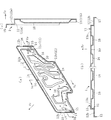
フランジ部12は、屈曲起立壁部11の先端部に繋がって屈曲起立壁部11とは交差する方向に屈曲しており、かつ本体部材2の上側および左右両側にそれぞれはみ出す上部1
2aおよび左右両側部12bを有している。このフランジ部12には、ビス止め用の複数の孔部14が設けられており、このフランジ部12を利用してガス供給用マニホールドAを所望の取付け対象部位に取付け可能である。フランジ部12の外周縁には、このフランジ部12を補強するための屈曲片部15が設けられている。フランジ部12の外周縁には、屈曲片部15が設けられていない箇所16があるが、この箇所16は、蓋部材1を順送プレス加工により製作する場合に、この蓋部材1を支持するための部分に該当する。
The
2a and left and
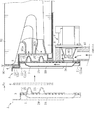
前記したガス供給用マニホールドAは、たとえば図6に示すような態様で用いられる。すなわち、本体部材2の前面部の下部には、開閉弁Vを備えた燃料ガス供給用の補助部材8が取付けられる。ガス管(不図示)から供給されてくる燃料ガスは、補助部材8内のガス供給流路81、および本体部材2の開口部26を通過してガス供給流路29に流入する。開閉弁Vは、開口部26を開閉自在である。補助部材8には、不図示の流量制御弁や元電磁弁なども適宜取り付けられる。
The above-described gas supply manifold A is used in a manner as shown in FIG. 6, for example. That is, an auxiliary member 8 for supplying fuel gas having an on-off valve V is attached to the lower part of the front surface portion of the
ガス供給用マニホールドAは、フランジ部12をバーナケース90にビス止め(不図示)することによりバーナケース90に取付けられ、複数のガス噴出ノズル25がバーナヘッド91のガス給気口92a,92bに対向接近するように設定される。このことにより、バーナヘッド91への燃料ガス供給が可能となり、バーナヘッド91において燃料ガスを燃焼させることができる。
The gas supply manifold A is attached to the
ガス供給用マニホールドAには、弾性部材からなるシール用のループ状パッキン4が付属して設けられている。このループ状パッキン4は、図7に示すように、たとえば正面視略矩形のループ状であり、その一部分は、本体部材2の前面側のうち、複数のガス噴出ノズル25の下側に位置して左右横幅方向に延びている。ループ状パッキン4の他の部分は、蓋部材1のフランジ部12の前面側に位置するように設定されている。ガス供給用マニホールドAの前後方向において、フランジ部12の前面と本体部材2の前面との間には、段差を生じているが、ループ状パッキン4は、可撓性に優れた材質とされ、そのような段差部分の位置に隙間を生じないように設定されている。図6に示すガス供給用マニホールドAの取付け状態において、ループ状パッキン4は、バーナケース90の正面視において、複数のガス噴出ノズル25の配置領域の周囲全周を囲んだ配置にあり、かつガス供給用マニホールドAとバーナケース90との間で圧縮された状態にある。このため、複数のガス噴出ノズル25から噴出された燃料ガスがループ状パッキン4の外部に不当に漏出することは適切に防止される。
The gas supply manifold A is provided with a sealing loop packing 4 made of an elastic member. As shown in FIG. 7, the loop packing 4 has, for example, a substantially rectangular loop shape when viewed from the front. A part of the loop packing 4 is located below the plurality of gas ejection nozzles 25 on the front side of the
次に、前記したガス供給用マニホールドAの作用について説明する。 Next, the operation of the gas supply manifold A will be described.
まず、蓋部材1に設けられたループ状の屈曲起立壁部11は、前後方向視において複数のガス供給流路29およびその周辺領域の全周を囲むように設けられており、それらの領域の強度を大きく向上させる。本実施形態とは異なり、蓋部材1にたとえば非ループ状の屈曲起立壁部を部分的に設けただけでは、ガス供給流路29およびその周辺領域の広い範囲を効率良く補強することはできず、また特定方向に反り変形を生じるといったことを適切に解消できないようなことも生じ得る。これに対し、ループ状の屈曲起立壁部11は、特定方向に反り変形を生じ易くなるといったこともなくし、ガス供給流路29およびその周辺領域に歪みを生じ難くする効果をもたらせる。
First, the loop-like bent
さらに、ループ状の屈曲起立壁部11の略全周域は、前後方向視において本体部材2と重なった配置に設けられているため、ガス供給流路29およびその周辺領域がより効率良く補強される。図8は、本実施形態との対比例であり、上側および下側の屈曲起立壁部11a,11b(11)が、本体部材2から適当な幅La,Lbではみ出している。この対比例も、本発明の技術的範囲に包摂されるものであるが、対比例においては、剛性の高い
屈曲起立壁部11を本体部材2に強く圧接させることができない。これに対し、本実施形態によれば、剛性の高い屈曲起立壁部11を本体部材2に強く圧接させることができる。また、これに加え、ループ状の屈曲起立壁部11によって囲まれる部分の面積を対比例の場合よりも小さくすることができる。このため、本実施形態では、ガス供給流路29およびその周辺領域を、一層効果的に補強することができる。
Furthermore, since the substantially entire circumferential area of the loop-shaped bent
このようなことから、蓋部材1の厚みを比較的薄くしたとしても、蓋部材1のガス供給流路29およびその周辺領域に大きな歪みを生じないようにし、本体部材2と蓋部材1との間に、ガス漏れの要因となる隙間を生じないようにすることが可能である。ガス漏れを防止するための手段として、蓋部材1と本体部材2とのビス止め箇所を多くするといった必要もなくすことが可能である。このようなことから、ガス供給用マニホールドAの軽量化や製造コストの低減化などを適切に図ることができる。
For this reason, even if the thickness of the
図3に示したように、シール用のパッキン3の位置決めを図る位置決め用凸部13は、本体部材2の凹部22に進入可能であるため、この位置決め用凸部13の突出寸法をパッキン3の厚みよりも大きくすることが可能である。これは、蓋部材1にパッキン3を組み付ける際に、パッキン3の孔部30から位置決め用凸部13が外れる虞を少なくし、パッキン3の組み付け作業性をよくする上で好ましい。一方、本体部材2の凹部22は、非貫通孔状であるため、この部分から外部へガス漏れを生じるようなこともない。
As shown in FIG. 3, the positioning
その他、本実施形態においては、図6および図7を参照して説明したように、蓋部材1のフランジ部12をバーナケース90への取付け部として用いることができるため、蓋部材1にループ状の屈曲起立壁部11を設けたことに起因してガス供給用マニホールドAの取付け性が悪くなるといった不具合もない。また、複数のガス噴出ノズル25から噴出された燃料ガスが外部に漏出することは、ループ状パッキン4を利用して適切に防止されるが、このループ状パッキン4は、フランジ部12および本体部材2の前面側に好適に配置させることができ、その装着作業なども容易である。
In addition, in this embodiment, as described with reference to FIGS. 6 and 7, since the
本発明は、上述した実施形態の内容に限定されない。本発明に係るガス供給用マニホールドの各部の具体的な構成は、本発明の意図する範囲内において種々に設計変更自在である。 The present invention is not limited to the contents of the above-described embodiment. The specific configuration of each part of the gas supply manifold according to the present invention can be variously modified within the range intended by the present invention.
本発明における屈曲起立壁部の具体的な形状(ループ形状)や起立寸法などは限定されない。
蓋部材と本体部材との連結は、ビス止めに限らず、たとえばビス以外のネジ体を用いる手段や、カシメなどの手段を用いて行なうことも可能である。
本発明に係るガス供給用マニホールドは、給湯装置の燃焼装置用に限定されず、その具体的な用途は限定されない。
The specific shape (loop shape) and the standing dimension of the bent upright wall portion in the present invention are not limited.
The connection between the lid member and the main body member is not limited to the screw fastening, and may be performed using, for example, a means using a screw body other than a screw or a caulking means.
The gas supply manifold according to the present invention is not limited to the combustion device of the hot water supply device, and its specific application is not limited.
A ガス供給用マニホールド
1 蓋部材
11 屈曲起立壁部
12 フランジ部
13 位置決め用凸部
2 本体部材
22 凹部(本体部材の)
25 ガス噴出ノズル
29 ガス供給流路
3 シール用のパッキン
30 孔部(シール用のパッキンの)
4 ループ状パッキン
90 バーナケース(取付け対象部位)
A
25
4 Loop packing 90 Burner case (attachment target part)
Claims (5)
この本体部材の片面に重ねられ、かつ前記本体部材に連結されている蓋部材と、
を備えており、
前記蓋部材と前記本体部材との間には、前記複数のガス噴出ノズルに連通するガス供給流路が形成されている、ガス供給用マニホールドであって、
前記蓋部材は、前記本体部材との重ね合わせ方向において、前記本体部材とは反対側に屈曲して起立した屈曲起立壁部を備え、かつこの屈曲起立壁部は、前記蓋部材と前記本体部材との重ね合わせ方向視において、前記ガス供給流路およびその周辺領域の全周を囲むループ状に形成されていることを特徴とする、ガス供給用マニホールド。 A main body member provided with a plurality of gas ejection nozzles;
A lid member overlaid on one side of the body member and connected to the body member;
With
A gas supply manifold in which gas supply passages communicating with the plurality of gas ejection nozzles are formed between the lid member and the main body member,
The lid member includes a bent upright wall portion that is bent and stands upright in an overlapping direction with the main body member, and the bent upright wall portion includes the lid member and the main body member. The gas supply manifold is formed in a loop shape that surrounds the entire circumference of the gas supply flow path and its peripheral region.
前記重ね合わせ方向視において、前記屈曲起立壁部の略全周域は、前記本体部材に重なった配置に形成されている、ガス供給用マニホールド。 The gas supply manifold according to claim 1,
A gas supply manifold in which substantially the entire peripheral area of the bent upright wall portion is formed so as to overlap the main body member when viewed in the overlapping direction.
前記蓋部材と前記本体部材との相互間に介装されるシール用のパッキンを、備えており、
前記蓋部材には、前記パッキンに設けられている孔部に挿通する位置決め用凸部が形成されており、
前記本体部材には、前記位置決め用凸部の先端部が進入するように前記位置決め用凸部の突出方向に窪んだ非貫通孔状の凹部が設けられている、ガス供給用マニホールド。 The gas supply manifold according to claim 1 or 2,
A seal packing interposed between the lid member and the main body member,
The lid member is formed with a positioning convex portion that is inserted into a hole provided in the packing,
A gas supply manifold, wherein the main body member is provided with a non-through-hole-shaped recess that is recessed in a protruding direction of the positioning convex portion so that a distal end portion of the positioning convex portion enters.
前記蓋部材には、前記屈曲起立壁部の先端部に繋がって屈曲し、かつ前記重ね合わせ方向視において、前記本体部材の外方にはみ出したフランジ部が設けられており、
このフランジ部は、所望の取付け対象部位への取付け部として用いられるように構成されている、ガス供給用マニホールド。 A gas supply manifold according to any one of claims 1 to 3,
The lid member is provided with a flange portion that is connected to the distal end portion of the bent upright wall portion and is bent and protrudes outward from the main body member in the overlapping direction view.
This flange portion is a gas supply manifold configured to be used as an attachment portion to a desired attachment target site.
前記フランジ部は、前記本体部材の起立姿勢状態において、前記本体部材の上側および左右両側にはみ出すように設けられており、
このガス供給用マニホールドを前記取付け対象部位に取付ける際には、シール用のループ状パッキンの一部分が、前記本体部材の前面側のうち、前記複数のガス噴出ノズルの下側に位置して左右横幅方向に延び、かつ前記ループ状パッキンの他の部分が、前記フランジ部の前面側に位置するように設定される構成とされている、ガス供給用マニホールド。 The gas supply manifold according to claim 4,
The flange portion is provided so as to protrude from the upper side and the left and right sides of the main body member in the standing posture state of the main body member,
When the gas supply manifold is attached to the attachment target portion, a part of the sealing loop-shaped packing is positioned below the plurality of gas ejection nozzles on the front side of the body member. A gas supply manifold that extends in a direction and is configured so that the other part of the loop packing is positioned on the front side of the flange portion.
Priority Applications (3)
| Application Number | Priority Date | Filing Date | Title |
|---|---|---|---|
| JP2016125930A JP6751258B2 (en) | 2016-06-24 | 2016-06-24 | Gas supply manifold |
| US15/624,393 US10309645B2 (en) | 2016-06-24 | 2017-06-15 | Gas supply manifold and gas combustion device provided with the same |
| CN201710457682.2A CN107543200B (en) | 2016-06-24 | 2017-06-16 | Gas supply manifold and gas combustion apparatus having the same |
Applications Claiming Priority (1)
| Application Number | Priority Date | Filing Date | Title |
|---|---|---|---|
| JP2016125930A JP6751258B2 (en) | 2016-06-24 | 2016-06-24 | Gas supply manifold |
Publications (2)
| Publication Number | Publication Date |
|---|---|
| JP2017227422A true JP2017227422A (en) | 2017-12-28 |
| JP6751258B2 JP6751258B2 (en) | 2020-09-02 |
Family
ID=60676825
Family Applications (1)
| Application Number | Title | Priority Date | Filing Date |
|---|---|---|---|
| JP2016125930A Active JP6751258B2 (en) | 2016-06-24 | 2016-06-24 | Gas supply manifold |
Country Status (3)
| Country | Link |
|---|---|
| US (1) | US10309645B2 (en) |
| JP (1) | JP6751258B2 (en) |
| CN (1) | CN107543200B (en) |
Cited By (1)
| Publication number | Priority date | Publication date | Assignee | Title |
|---|---|---|---|---|
| JP2021025739A (en) * | 2019-08-08 | 2021-02-22 | リンナイ株式会社 | Water heater |
Families Citing this family (2)
| Publication number | Priority date | Publication date | Assignee | Title |
|---|---|---|---|---|
| US10288313B2 (en) * | 2015-12-25 | 2019-05-14 | Noritz Corporation | Gas supply manifold and production method of gas supply manifold |
| JP6751258B2 (en) * | 2016-06-24 | 2020-09-02 | 株式会社ノーリツ | Gas supply manifold |
Citations (2)
| Publication number | Priority date | Publication date | Assignee | Title |
|---|---|---|---|---|
| JP2003065507A (en) * | 2001-08-23 | 2003-03-05 | Noritz Corp | Manifold device for supplying gas and gas combustion equipment having the device |
| JP2015143588A (en) * | 2014-01-31 | 2015-08-06 | リンナイ株式会社 | Manifold for gas supply |
Family Cites Families (13)
| Publication number | Priority date | Publication date | Assignee | Title |
|---|---|---|---|---|
| JP2004197971A (en) | 2002-12-16 | 2004-07-15 | Noritz Corp | Manifold device to supply gas, and gas combustor provided with the same |
| JP2011252671A (en) * | 2010-06-03 | 2011-12-15 | Rinnai Corp | Combustion apparatus |
| CN102537962B (en) * | 2010-12-16 | 2015-06-03 | 株式会社能率 | Rich-lean combustion burner |
| US20120219920A1 (en) * | 2011-02-28 | 2012-08-30 | Noritz Corporation | Rich-lean combustion burner |
| JP5716551B2 (en) * | 2011-05-30 | 2015-05-13 | 株式会社ノーリツ | Tint burning burner |
| CN103162290B (en) * | 2011-12-09 | 2016-08-03 | 株式会社能率 | Rich-lean combustion burner and burner |
| CN103185339B (en) * | 2011-12-28 | 2016-08-03 | 株式会社能率 | Rich-lean combustion burner and burner |
| CN103727133A (en) * | 2012-10-15 | 2014-04-16 | 洛阳伊崧精密轴承技术开发有限公司 | Whole-stamping retainer structure for tapered roller bearings |
| JP5997872B2 (en) * | 2014-04-02 | 2016-09-28 | リンナイ株式会社 | Manifold for gas supply |
| US20150369479A1 (en) * | 2014-06-20 | 2015-12-24 | Rinnai Corporation | Flat burner |
| JP6504520B2 (en) * | 2015-03-26 | 2019-04-24 | 株式会社ノーリツ | Combustion device |
| US10288313B2 (en) * | 2015-12-25 | 2019-05-14 | Noritz Corporation | Gas supply manifold and production method of gas supply manifold |
| JP6751258B2 (en) * | 2016-06-24 | 2020-09-02 | 株式会社ノーリツ | Gas supply manifold |
-
2016
- 2016-06-24 JP JP2016125930A patent/JP6751258B2/en active Active
-
2017
- 2017-06-15 US US15/624,393 patent/US10309645B2/en active Active
- 2017-06-16 CN CN201710457682.2A patent/CN107543200B/en active Active
Patent Citations (2)
| Publication number | Priority date | Publication date | Assignee | Title |
|---|---|---|---|---|
| JP2003065507A (en) * | 2001-08-23 | 2003-03-05 | Noritz Corp | Manifold device for supplying gas and gas combustion equipment having the device |
| JP2015143588A (en) * | 2014-01-31 | 2015-08-06 | リンナイ株式会社 | Manifold for gas supply |
Cited By (2)
| Publication number | Priority date | Publication date | Assignee | Title |
|---|---|---|---|---|
| JP2021025739A (en) * | 2019-08-08 | 2021-02-22 | リンナイ株式会社 | Water heater |
| JP7274255B2 (en) | 2019-08-08 | 2023-05-16 | リンナイ株式会社 | Water heater |
Also Published As
| Publication number | Publication date |
|---|---|
| CN107543200B (en) | 2021-05-07 |
| US10309645B2 (en) | 2019-06-04 |
| US20170370574A1 (en) | 2017-12-28 |
| CN107543200A (en) | 2018-01-05 |
| JP6751258B2 (en) | 2020-09-02 |
Similar Documents
| Publication | Publication Date | Title |
|---|---|---|
| JP2017227422A (en) | Manifold for gas supply | |
| KR20190009266A (en) | all primary combustion type burner | |
| JP2006284127A (en) | Gas turbine combustor | |
| US8117835B2 (en) | Gasket | |
| JP5921584B2 (en) | Manifold for gas supply | |
| WO2019181657A1 (en) | Fluid device | |
| JP4967811B2 (en) | Metal member joining structure and metal case having this structure | |
| KR20090057362A (en) | Structure for exhaust pipe connection section of muffler | |
| JP4560007B2 (en) | Cylinder head gasket | |
| CN107461923B (en) | Heat source machine | |
| JP6475092B2 (en) | Combustion device | |
| JP2005114053A (en) | Metal gasket | |
| JP2017116209A (en) | Manifold for gas supply and manufacturing method of the same | |
| JP6691439B2 (en) | Heat source machine | |
| JP2010505068A (en) | Sealing tool | |
| JP2007120467A (en) | Secondary air supply structure for internal combustion engine | |
| JP2008223581A (en) | Metal gasket | |
| JP2005155713A (en) | Metallic gasket | |
| JP6880399B2 (en) | gasket | |
| JP6176473B2 (en) | Cylinder head gasket | |
| JP2008107020A (en) | Heat source machine | |
| JP2018054151A (en) | Burner device | |
| JP4707699B2 (en) | Exhaust manifold in internal combustion engines | |
| TWI621573B (en) | Water storage device | |
| JP2017198288A (en) | gasket |
Legal Events
| Date | Code | Title | Description |
|---|---|---|---|
| A621 | Written request for application examination |
Free format text: JAPANESE INTERMEDIATE CODE: A621 Effective date: 20190530 |
|
| A977 | Report on retrieval |
Free format text: JAPANESE INTERMEDIATE CODE: A971007 Effective date: 20200311 |
|
| A131 | Notification of reasons for refusal |
Free format text: JAPANESE INTERMEDIATE CODE: A131 Effective date: 20200318 |
|
| A521 | Request for written amendment filed |
Free format text: JAPANESE INTERMEDIATE CODE: A523 Effective date: 20200507 |
|
| TRDD | Decision of grant or rejection written | ||
| A01 | Written decision to grant a patent or to grant a registration (utility model) |
Free format text: JAPANESE INTERMEDIATE CODE: A01 Effective date: 20200715 |
|
| A61 | First payment of annual fees (during grant procedure) |
Free format text: JAPANESE INTERMEDIATE CODE: A61 Effective date: 20200728 |
|
| R150 | Certificate of patent or registration of utility model |
Ref document number: 6751258 Country of ref document: JP Free format text: JAPANESE INTERMEDIATE CODE: R150 |