JP2017227117A - Sleeper, sleeper laying method, and sleeper manufacturing method - Google Patents
Sleeper, sleeper laying method, and sleeper manufacturing method Download PDFInfo
- Publication number
- JP2017227117A JP2017227117A JP2017120441A JP2017120441A JP2017227117A JP 2017227117 A JP2017227117 A JP 2017227117A JP 2017120441 A JP2017120441 A JP 2017120441A JP 2017120441 A JP2017120441 A JP 2017120441A JP 2017227117 A JP2017227117 A JP 2017227117A
- Authority
- JP
- Japan
- Prior art keywords
- sleeper
- laying
- sleepers
- rail
- core
- Prior art date
- Legal status (The legal status is an assumption and is not a legal conclusion. Google has not performed a legal analysis and makes no representation as to the accuracy of the status listed.)
- Pending
Links
Images


Abstract
Description
本発明は、鉄道軌道に用いられる枕木およびその敷設方法並びに枕木の製造方法に関し、特に軽量化可能な合成枕木およびその敷設方法並びに製造方法に利用して有効な技術に関する。 The present invention relates to a sleeper used for a railway track, a method for laying the sleeper, and a method for manufacturing the sleeper, and more particularly, to a technique effective for use in a synthetic sleeper that can be reduced in weight, and a method for laying and manufacturing the sleeper.
従来、鉄道軌道の枕木としては、バラスト軌道で用いられる木製の枕木やプレストレスト・コンクリート製のPC枕木が一般的である。また、軽量化を目的として、ガラス繊維と硬質発泡ウレタンなどの合成樹脂で構成された複合材料からなる合成枕木も一部で使用されている。
なお、従来提案されている合成枕木に関する発明としては、例えば特許文献1や特許文献2に開示されているものがある。
Conventionally, sleepers for railroad tracks are generally wooden sleepers used on ballast tracks and PC sleepers made of prestressed concrete. In addition, for the purpose of weight reduction, a synthetic sleeper made of a composite material made of a synthetic resin such as glass fiber and rigid urethane foam is also used in part.
In addition, as invention regarding the synthetic sleeper proposed conventionally, there exist some which are disclosed by patent document 1 and patent document 2, for example.
特許文献1や特許文献2に開示されている合成枕木は、いずれも芯材とその周囲を囲む表層材とで構成することによって、軽量で曲げ強度の高い枕木を提供するものである。
ところで、バラスト軌道において、木製の枕木を耐久性の高いPC枕木に置き換える工事が行われることがあるが、その場合、枕木を1本ずつ置き換える方法と、レールと枕木とを梯子状に組み立てた軌きょうの状態で設置する方法がある。
The synthetic sleepers disclosed in Patent Document 1 and Patent Document 2 are both composed of a core material and a surface layer material surrounding the core material, thereby providing a light sleeper with high bending strength.
By the way, in a ballast track, there are cases where construction work is performed to replace wooden sleepers with highly durable PC sleepers. In that case, a method of replacing sleepers one by one, and a rail with rails and sleepers assembled in a ladder shape. There is a method to install in the current state.
枕木を1本ずつ置き換える場合には、先ず枕木上のレールを締結器から解放し、枕木周囲のバラストを除去してから木製枕木を引き抜き、代わりにPC枕木を差し込んで、バラストを埋め戻した後、レールを締結器で固定する作業を行うこととなる。このような作業を人手で行うことができるが、PC枕木は重量が非常に重いため、かなりの労力と時間を必要としており、作業効率が悪いという課題があった。
一方、軌きょうの状態で設置する方法の場合、軌きょうの重量が非常に重くなるため、特殊な大型重機を使用する大掛かりな工事になってしまうという課題がある。
When replacing sleepers one by one, first release the rails on the sleepers from the fasteners, remove the ballast around the sleepers, pull out the wooden sleepers, insert the PC sleepers instead, and backfill the ballast Then, the work of fixing the rail with a fastener is performed. Although such operations can be performed manually, the PC sleepers are extremely heavy, requiring considerable labor and time, and there is a problem that the work efficiency is poor.
On the other hand, in the case of the method of installing in the state of a rail, since the weight of a rail becomes very heavy, there exists a subject that it will be a large-scale construction using a special large sized heavy machine.
そこで、特許文献1や特許文献2に開示されているような軽量の合成枕木を使用することで、枕木の取替え工事の負担を減らすことができる。
ところで、バラスト軌道においては、レールを支える枕木が上下方向や横方向に変位を起こしてレールが変形するおそれがあるため、変位を防止する対策が要望されている。なお、枕木の変位を防止する上では、枕木の重量が重く、道床に対する抵抗力が大きい方が良いことが知られている。
Therefore, by using a lightweight synthetic sleeper as disclosed in Patent Document 1 and Patent Document 2, it is possible to reduce the burden of sleeper replacement work.
By the way, in a ballast track, since the sleepers supporting the rail may be displaced in the vertical direction or the horizontal direction and the rail may be deformed, a countermeasure for preventing the displacement is desired. In order to prevent displacement of sleepers, it is known that the weight of sleepers is heavier and the resistance to the road bed is greater.
しかしながら、合成枕木は軽量であるので、取替えや敷設の工事は容易となるが、道床横抵抗力が小さいという課題がある。
なお、特許文献1や特許文献2の発明に係る合成枕木は、軽量化を図るため芯材と表層材のいずれも合成樹脂を使用しており、道床横抵抗力を高めるという発想がない。
However, since synthetic sleepers are lightweight, replacement and laying work are easy, but there is a problem that the lateral resistance of the road bed is small.
Note that the synthetic sleepers according to the inventions of Patent Document 1 and Patent Document 2 use a synthetic resin for both the core material and the surface layer material in order to reduce the weight, and there is no idea of increasing the lateral resistance of the road bed.
本発明は、上記のような課題に鑑みてなされたものであり、敷設時には軽量で取り扱いが容易であり、敷設後は重量が重く道床での変位を充分に防止することができる枕木およびその敷設方法並びに製造方法を提供することを目的とする。
本発明の他の目的は、営業列車が走行しない夜間等の比較的短い時間内に暫定的な敷設作業を完了することができる枕木およびその敷設方法を提供することにある。
The present invention has been made in view of the problems as described above, and is lightweight and easy to handle at the time of laying, and after laying, a sleeper capable of sufficiently preventing displacement on the roadbed and its laying. It aims at providing a method and a manufacturing method.
Another object of the present invention is to provide a sleeper capable of completing provisional laying work within a relatively short time such as at night when a commercial train does not travel, and a laying method thereof.
上記目的を達成するため、この発明に係る枕木は、
複合材料で形成された直方体状の枕木本体内部に空洞部が設けられているとともに、表面のいずれかの部位から前記空洞部に連通する連通部が設けられているようにしたものである。
In order to achieve the above object, a sleeper according to the present invention is:
A hollow portion is provided inside a rectangular parallelepiped sleeper main body formed of a composite material, and a communication portion communicating with the hollow portion from any part of the surface is provided.
上記のような構成によれば、枕木本体に空洞部が形成されているため、敷設時には軽量で取り扱いが容易であるとともに、敷設後には上記空洞部内に枕木本体の材料よりも比重の大きい充填材を注入することで重量を増加させることでき、これによって道床横抵抗力を高め、レールの変位を充分に防止することができる。 According to the configuration as described above, since the hollow portion is formed in the sleeper body, it is light and easy to handle when laying, and after laying, the filler has a larger specific gravity than the material of the sleeper body in the hollow portion. The weight can be increased by injecting, thereby increasing the lateral resistance of the road bed and sufficiently preventing the rail from being displaced.
また、望ましくは、前記枕木本体の敷設後にレールが載置される箇所に対応した部位に、上面が当該枕木本体の上面と連続し前記空洞部を分断する仕切り部が設けられているようにする。
かかる構成によれば、枕木本体の敷設後、空洞部内に充填材を注入する前に、レールを載置して締結器で固定することで、営業列車が走行しない夜間等の比較的短い時間内に暫定的な敷設作業を完了することができる。
In addition, preferably, a partition portion that is continuous with the upper surface of the sleeper main body and that divides the cavity portion is provided at a portion corresponding to a position where the rail is placed after the sleeper main body is laid. .
According to such a configuration, after laying the sleeper main body and before injecting the filler into the cavity, the rail is placed and fixed with a fastener, so that the business train does not run in a relatively short time such as at night. Provisional laying work can be completed.
さらに、望ましくは、前記仕切り部の上面に、レール締結器の部品が係止される係止金具が設けられている構成とする。
このような構成によれば、レールを載置して締結器で固定する作業を短時間に完了することができる。また、予め枕木とレールとを結合して軌きょうを作成し、この軌きょうを道床上に敷設するという手順を採用することで、枕木の交換作業に要する時間を短縮することができるとともに、枕木本体が軽量であるため、特殊な大型重機を使用することなく、クレーンを備えた一般的な軌陸車によって軌きょうを持ち上げて敷設することができる。
Furthermore, it is desirable that a locking bracket for locking a part of the rail fastener is provided on the upper surface of the partition part.
According to such a structure, the operation | work which mounts a rail and fixes with a fastener can be completed in a short time. In addition, it is possible to reduce the time required for the sleeper replacement work by adopting a procedure in which sleepers and rails are combined in advance to create a rail and laying this rail on the roadbed. Since the main body is lightweight, the rail can be lifted and laid by a general rail vehicle equipped with a crane without using special large heavy machinery.
また、望ましくは、前記枕木本体内に、当該枕木本体の長手方向に沿って複数の筒状空洞部が設けられ、そのうち1つは壁体を有して他の筒状空洞部と非連通とされているように構成する。
かかる構成によれば、枕木本体内に他の円筒状空洞部と非連通の空洞部が設けられるため、この空洞部を、軌道を横断するように配設したいケーブルを挿通する空間として利用することができ、従来に比べてケーブルの配設作業を容易に行うことができるとともに、配設したケーブルを覆うカバーを設ける必要もない。
Desirably, a plurality of cylindrical cavities are provided in the sleeper main body along the longitudinal direction of the sleeper main body, one of which has a wall and is not in communication with other cylindrical cavities. Configure as it is.
According to such a configuration, since a hollow portion that is not in communication with the other cylindrical hollow portion is provided in the sleeper body, this hollow portion can be used as a space for inserting a cable to be disposed so as to cross the track. As compared with the prior art, the cable can be arranged more easily and there is no need to provide a cover for covering the arranged cable.
また、本出願の他の発明に係る枕木の敷設方法は、
上記のように構成された枕木本体を道床上に敷設する工程と、
敷設された前記枕木本体の前記仕切り部の上面にレールを載置する工程と、
前記仕切り部の上に載置されたレールをレール締結器で固定する工程と、
前記枕木本体の前記空洞部内に当該枕木本体の材料よりも比重の大きい充填材を注入する工程と、
を有するようにしたものである。
かかる方法によれば、営業列車が走行しない夜間等の比較的短い時間内に暫定的な敷設作業を完了することができる。そして、枕木敷設後に、枕木内の空洞部に比重の大きい充填材を注入することで重量を増加させ、道床横抵抗力を高めすることができる。
In addition, a method for laying sleepers according to another invention of the present application,
Laying a sleeper body configured as described above on the roadbed;
Placing a rail on the upper surface of the partition portion of the sleeper body laid,
Fixing the rail placed on the partition with a rail fastener;
Injecting a filler having a specific gravity greater than the material of the sleeper body into the cavity of the sleeper body;
It is made to have.
According to this method, provisional laying work can be completed within a relatively short time such as at night when the business train does not travel. And after laying a sleeper, weight can be increased by inject | pouring a filler with large specific gravity into the cavity part in a sleeper, and a roadbed lateral resistance can be heightened.
さらに、本出願の他の発明に係る枕木の製造方法は、
枕木の外形に対応したほぼ長方形の空洞を有する型枠の空洞底部に強化用繊維を所定の厚みに敷き詰める工程と、
強化用繊維が敷き詰められた前記型枠内の所定位置に、中子を設置する工程と、
前記中子の周囲に強化用繊維を挿入する工程と、
前記型枠内に樹脂を流し込み硬化させる工程と、
を有するようにしたものである。
かかる方法によれば、内部に空洞部を有することで軽量化され、移送および配設作業が容易な枕木を安価に製造することができる。
Furthermore, the manufacturing method of the sleeper according to another invention of the present application,
Laying reinforcing fibers in a predetermined thickness on the cavity bottom of a formwork having a substantially rectangular cavity corresponding to the outer shape of the sleepers;
A step of installing a core at a predetermined position in the mold frame laid with reinforcing fibers;
Inserting reinforcing fibers around the core;
Pouring a resin into the mold and curing it;
It is made to have.
According to this method, it is possible to manufacture a sleeper that is reduced in weight by having a hollow portion therein and that can be easily transferred and disposed at low cost.
また、望ましくは、前記中子は、内部に空間を有し壁体の一部が開口可能であって型崩れしない強度を有する箱体の内部に流動性物質が充填されたものであり、
前記型枠内に樹脂を流し込み硬化させる工程の後に、前記流動性物質を前記箱体内から取り出す工程を有するようにする。
かかる方法によれば、中子を構成する箱体として安価な段ボールやプラスチックケースを使用できるとともに、内部に充填する流動性物質として砂等の安価な材料を使用することができるため、軽量化のための空洞を有する枕木の製造コストをさらに低減することができる。
Preferably, the core has a space inside, a part of the wall body can be opened, and the inside of the box body having a strength that does not lose its shape is filled with a fluid substance.
After the step of pouring the resin into the mold and curing it, there is a step of taking out the fluid substance from the box.
According to such a method, an inexpensive cardboard or plastic case can be used as a box constituting the core, and an inexpensive material such as sand can be used as a fluid substance to be filled therein. Therefore, it is possible to further reduce the manufacturing cost of the sleepers having the cavities.
さらに、望ましくは、前記中子は、流動性物質が充填された複数の箱体を並べて配置したものであり、
前記型枠内に樹脂を流し込み硬化させる工程の後に、前記複数の箱体の接合部の一部を破断する工程を有するようにする。
かかる方法によれば、流動性物質が充填された複数の箱体を並べて配置することで中子を構成するので、中子の設置作業が容易に行なえるとともに、型枠内に樹脂を流し込み硬化させる工程の後に、複数の箱体の接合部の一部を破断する工程を有するので、脱型後にすべての箱体内の流動性物質を取り出すことができる。
Furthermore, desirably, the core is a plurality of boxes that are filled with a fluid substance and arranged side by side.
After the step of pouring the resin into the mold and curing it, there is a step of breaking a part of the joint portions of the plurality of boxes.
According to this method, since the core is configured by arranging a plurality of boxes filled with a fluid substance side by side, the core can be easily installed and the resin is poured into the mold and cured. Since it has the process of fracture | rupturing a part of junction part of a some box body after the process to make, the fluid substance in all the boxes can be taken out after mold release.
本発明に係る枕木および敷設方法によれば、敷設時には軽量で取り扱いが容易であり、敷設後に重量を重くすることができ、道床での変位を充分に防止することができる。また、本発明に係る枕木およびその敷設方法によれば、営業列車が走行しない夜間等の比較的短い時間内に暫定的な敷設作業を完了することができるという効果がある。 According to the sleeper and the laying method according to the present invention, it is lightweight and easy to handle when laying, can be increased in weight after laying, and displacement on the roadbed can be sufficiently prevented. Moreover, according to the sleeper and its laying method according to the present invention, there is an effect that provisional laying work can be completed within a relatively short time such as at night when the business train does not travel.
以下、図面を参照して、本発明に係る枕木の実施形態について詳細に説明する。
(第1実施形態)
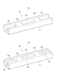
図1は、第1実施形態の枕木の構成を示すものである。このうち、(A)は敷設前もしくは敷設直後の枕木の全体を示す斜視図、(B)は敷設後に充填材の注入を行なった完成状態の枕木の斜視図である。
Hereinafter, embodiments of sleepers according to the present invention will be described in detail with reference to the drawings.
(First embodiment)
FIG. 1 shows the structure of a sleeper according to the first embodiment. Among these, (A) is a perspective view showing the whole sleeper before laying or just after laying, and (B) is a perspective view of a sleeper in a completed state in which a filler is injected after laying.
図1(A)に示すように、本実施形態の枕木10は、直方体状の枕木本体11の上部に、3個の凹部12a,12b,12cが空洞部として形成されている。枕木本体11は、ガラス繊維と硬質発泡ウレタンなどの合成樹脂で構成された複合材料からなる合成枕木である。凹部12aと12bとの間の仕切り部13aおよび凹部12bと12cとの間の仕切り部13bは、道床への敷設後にレールが載置される箇所に対応して形成されている。仕切り部13a,13bには、図2(A)に示すように、ショルダーや植え込みボルトのようなレール締結器(クリップ等)が係止される係止金具15が予め埋設されていても良い。
As shown in FIG. 1 (A), the
本実施形態の枕木10は、上記凹部12a,12b,12c内に、例えばコンクリートあるいはモルタルのような、枕木本体11を構成する複合材料よりも比重の大きな材料が充填され固化することで、図1(B)に示すような完成状態となる。図1(B)において、符号20が付されている部位が、固化した充填材である。凹部12a,12b,12c内にコンクリートのような流動性のある材料を充填する際には、枕木本体11の両側部にそれぞれ型枠を設置しておくと良い。
The
充填材20の中には、鉄等の金属塊をインサートしておくことにより枕木全体の重量が、コンクリートのみからなる枕木よりも重くなるように構成しても良い。また、充填材20として、コンクリートの代わりに、鉄や鉛などの金属ブロックを挿入したものであっても良い。このような金属ブロックを使用する場合には、別途上記凹部12a,12b,12cの形状に対応した形状の金属ブロックを製造し、枕木の敷設後に、それらの金属ブロックを凹部12a,12b,12cに嵌合させ、金属ブロックと枕木本体11との隙間に接着剤等を装填して一体化させることができる。
You may comprise in the
バラスト軌道の木製枕木を1本ずつ、本実施形態の枕木10で置き換える場合には、先ず枕木上のレール締結器を解放し、枕木周囲のバラストを除去してから木製枕木を引き抜き、代わりに本実施形態の枕木10を差し込んで、バラストを埋め戻した後、レールを締結器で固定する作業を行う。
When replacing the wooden sleepers on the ballast track one by one with the
本実施形態の枕木10は、敷設直後は凹部12a,12b,12cが空洞のままであるが、このような空洞がある状態でも、木製の枕木と同等もしくはそれ以上の曲げ強度を有するように、凹部12a,12b,12cのサイズが予め設定されている。もともと合成枕木は、木製の枕木に比べて充分な曲げ強度を有しており、凹部を形成しても木製枕木の曲げ強度以上の曲げ強度を有する合成枕木を形成することは充分に可能である。
In the
そのため、上記のように空洞がある状態で敷設されている枕木の上を列車が走行しても何ら問題はない。そして、上記の枕木敷設工事が終了したあとで、時間をかけて順番に、凹部12a,12b,12c内にコンクリートのような充填材を流し込んで固化させることができ、それによって枕木の重量を増加させて、道床横抵抗力を高めることができる。
Therefore, there is no problem even if the train runs on the sleepers that are laid with a cavity as described above. Then, after the sleeper laying work is completed, a filler such as concrete can be poured into the
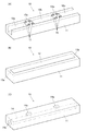
なお、枕木敷設直後に列車を走行させなくてもよい場合には、仕切り部13a,13bを、レールに対応する位置でなく、例えば図2(B)に示すように、枕木の両端に設け、連続した凹部12を形成することも可能である。
また、図2(C)に示すように、枕木本体11の内部に長手方向に延びる空洞14を形成し、上面等の一部に上記空洞14と連通した連通する連通部14aを設けるようにすることも可能である。
In addition, when it is not necessary to run the train immediately after laying the sleepers, the
Further, as shown in FIG. 2C, a
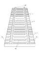
また、本実施形態の枕木10は、図3に示すように、レールと枕木とを梯子状に組み立てた軌きょうの状態で道床上に設置することが可能である。
そして、本実施形態の枕木10は、前述したように、敷設前は凹部を有しており、従来の合成枕木に比べて重量が約半分であるため、軌きょうに組み立てた状態の重量を大幅に低減することができる。その結果、特殊な大型重機を使用せずに、クレーンを有する一般的な軌陸車で敷設工事を行うことが可能となる。なお、図3においては、レール締結器の図示を省略している。
Moreover, as shown in FIG. 3, the
And the
以上本発明者によってなされた発明を実施形態に基づき具体的に説明したが、本発明は前記実施形態に限定されるものではない。例えば、前記実施形態においては、図1(B)の状態をもって完成状態であると説明したが、枕木本体11と凹部内のコンクリートやモルタルなどの充填材20の上に樹脂などからなる表面保護層を形成して完成状態としても良い。 また、前記実施形態においては、充填材が注入される凹部を枕木本体11の上面に設けたものを示したが、凹部の位置は上面に限定されず側面、前面、後面等であっても良い。
Although the invention made by the present inventor has been specifically described based on the embodiment, the present invention is not limited to the embodiment. For example, in the above-described embodiment, the state shown in FIG. 1B is described as a completed state. However, the surface protective layer made of resin or the like on the
(第2実施形態)
次に、本発明に係る枕木の第2実施形態およびその製造方法について説明する。
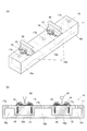
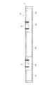
第2実施形態の枕木10の第1実施例は、図4(A)に示すように、複合材料からなる枕木本体11内に、上面にショルダー15が設けられる仕切り部13a,13bを挟むようにして、3つの直方体状の空洞部16a,16b,16cを形成し、本体上部に各空洞部16a,16b,16cを外部空間に連通させるための連通口17a,17b,17cを設けたものである。
(Second Embodiment)
Next, a second embodiment of a sleeper according to the present invention and a manufacturing method thereof will be described.
In the first example of the
図4(B)には、図4(A)に示す枕木10を長手方向に沿って断面した構造が示されている。図4(B)において、符号18が付されているのは、ショルダー15を固定するための植え込みボルトであり、枕木本体11の仕切り部13a,13bを構成する複合材料内に埋設されている。また、符号19が付されているのは、ショルダー15に挿通されレール30のフランジを締結するためクリップである。
FIG. 4B shows a structure in which the
図5には第2実施形態の枕木10の第2実施例が示されている。
第2実施例の枕木10は、図5(A)に示すように、枕木本体11内の3つの空洞部16a,16b,16cの下部にこれらの空洞部を連通させるように連通空洞部16dを設けたもので、この点以外は図4の第1実施例の枕木の構成と同じである。
図4の第1実施例および図5の第2実施例の枕木においては、後に詳しく説明するように、中子を用いて空洞部16a〜16dが形成される。また、枕木10は、製造後、空洞状態のまま移送され、枕木が道床に設置された後で、連通口17a,17b,17cより各空洞部16a〜16d内にコンクリートやモルタルなどが充填され、固化される。これによって、枕木の重量を増加させて、道床横抵抗力を高めることができる。
The 2nd Example of the
As shown in FIG. 5 (A), the
In the sleepers of the first embodiment of FIG. 4 and the second embodiment of FIG. 5,
図6には第2実施形態の枕木10の第3実施例が示されている。
第3実施例の枕木10は、図6(A)に示すように、枕木本体11内に、3個の円筒を横に並べた2段計4つの空洞部16A,16B,16C,16Dを設けたもので、上段の空洞部16A,16B,16Cは仕切り部13a,13bを挟むようにして分割されているとともに、下段の空洞部16Dは長手方向に連続して形成されている。これらの円筒状空洞部16A〜16Dは、図4の第1実施例および図5の第2実施例と同様に中子(形状は直方体ではなく円筒状)を用いて形成されるとともに、互いに接線の一部でそれぞれ連通されるように構成されている。
FIG. 6 shows a third example of the
As shown in FIG. 6 (A), the
また、下段の空洞部16Dの3本の円筒状部のうち1本は、他の空洞部(16A,16B,16Cを含む)と非連通になるように形成されていても良い。このような非連通の空洞部を設けることで、該空洞部を、軌道を横切るように配設されるケーブルを挿通するための空間として利用することができる。
従来の枕木を使用した軌道においては、軌道を横切るようにケーブルを配設する場合、枕木とバラストとの間に隙間を作るなどの作業や配設後にケーブルをカバーで覆う作業などが必要であったが、本実施例のようにケーブルを挿通するための空洞部を有する枕木を使用することで、軌道を横断するケーブルを配設したい場合に、その配設作業を容易に行うことができるようになるとともに、配設したケーブルを覆うカバーを設ける必要もないという利点がある。
Further, one of the three cylindrical portions of the lower
In a track using conventional sleepers, when a cable is arranged so as to cross the track, an operation such as creating a gap between the sleeper and the ballast, and a work of covering the cable with a cover after the arrangement are necessary. However, when a sleeper having a hollow portion for inserting a cable as in this embodiment is used, when a cable that traverses the track is to be arranged, the arrangement work can be easily performed. In addition, there is an advantage that it is not necessary to provide a cover for covering the arranged cable.
次に、上記2実施形態のような軽量化した枕木の製造方法の
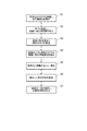
例について、図7のフローチャートを用いて説明する。
先ず、製造したい枕木の枕木本体11の外形に対応した凹部を有する成形用の型枠と、枕木内部に形成したい空洞の形状に対応した外形(直方体、円筒状等)を有する中子とを準備し、型枠の底に、空洞部16a〜16dの底壁部分の厚みに相当する厚さとなるよう、ガラス繊維のような強化用繊維を敷き詰める(ステップS1)。続いて、敷き詰めた強化用繊維層の上に中子を配置し、中子の周囲の型枠との隙間に強化用繊維を挿入する(ステップS2)。
Next, an example of a method for manufacturing a lightweight sleeper as in the above-described two embodiments will be described with reference to the flowchart of FIG.
First, a forming mold having a recess corresponding to the outer shape of the sleeper
中子は、例えば段ボールもしくは厚紙あるいはポリプロピレン等、シート状態において型崩れを起こさない程度の強度を有する材料で形成された容器を用いる。そして、各容器の中に砂のような流動性物質を充填する。上記容器形成材料のうち特に段ボールを使用した場合には、極めて安価に中子を形成することができる。流動性物質は、砂に限定されず、ガラスビーズなどの粒状物あるいは液状物を使用しても良い。 For the core, for example, a container formed of a material having a strength that does not cause deformation in the sheet state, such as cardboard, cardboard, or polypropylene, is used. Then, each container is filled with a fluid substance such as sand. In the case where corrugated cardboard is used among the container forming materials, the core can be formed at a very low cost. The fluid substance is not limited to sand, and may be a granular material such as glass beads or a liquid material.
また、例えば図5の第2実施例のような枕木においては、連続している中子全体を1つの容器として構成することも可能であるが、図8に示すように、5個の容器C1〜C5を並べることで構成しても良い。図8の場合、枕木1個に対し、大きさの異なる3種類5個の容器が必要となる。なお、中子を構成する容器の数は5個に限定されず、さらに多くの数の容器に分けても良い。また、例えばより小さな同一形状の容器を並べて所定の大きさの中子を構成するようにしても良い。 Further, for example, in the sleeper as in the second embodiment of FIG. 5, it is possible to configure the entire continuous core as one container, but as shown in FIG. 8, there are five containers C1. ˜C5 may be arranged. In the case of FIG. 8, three types of five containers having different sizes are required for one sleeper. The number of containers constituting the core is not limited to five, and may be divided into a larger number of containers. Further, for example, smaller cores having the same shape may be arranged to form a core having a predetermined size.
ステップS2に続いて、連通口17a,17b,17cに相当する位置に筒状中子を縦向きにして配置する(ステップS3)。なお、埋め込みボルトを設ける枕木においては、ステップS3で、枕木本体の仕切り部となる部位に埋め込みボルトを配置する。次に、空洞部形成用の中子(容器C1〜C5)の上方および連通口形成用の筒状中子の周囲に強化用繊維を敷き詰め(ステップS4)、ウレタン等の合成樹脂を型枠内に注入し、硬化させる(ステップS5)。筒状中子は、容器C1〜C5と同様に流動性物質を充填したものでも良いし、容器C1〜C5よりも厚みを厚くすることで、空の状態のまま配置しても良い。
Subsequent to step S2, the cylindrical core is disposed vertically at a position corresponding to the
ステップS5の後、固化した枕木本体を型枠から外し(ステップS6)、枕木本体を横向きあるいは逆さにして筒状中子から流動性物質を除去し、該筒状中子の内側にカッター等の工具を差し込んで、中子として使用した容器C1〜C5の接合面の一部を破断させてすべての容器から流動性物質を流出させ(ステップS7)、完成状態となる。 After step S5, the solidified sleeper body is removed from the mold (step S6), the sleeper body is turned sideways or upside down to remove the fluid substance from the cylindrical core, and a cutter or the like is placed inside the cylindrical core. A tool is inserted, a part of the joint surface of the containers C1 to C5 used as the core is broken, and the flowable substance is allowed to flow out from all the containers (step S7), thereby completing a completed state.
なお、上記手順は一例であり、種々の変形が可能である。例えば連通口17a,17b,17cに相当する位置に、筒状中子を縦向きにして配置するステップS3をなくし、代わりに、ステップS6の後に、連通口17a,17b,17cに相当する位置にドリル等で穴をあける工程を設けるようにしても良い。
また、上記手順では、枕木を正規の姿勢(道床設置時に上面となる面が製造時に上となる状態)で製造する場合を想定して説明したが、枕木が逆さの姿勢で完成するように製造することも可能である。
In addition, the said procedure is an example and various deformation | transformation are possible. For example, the step S3 in which the cylindrical core is disposed vertically in the position corresponding to the
Moreover, in the above procedure, the case where the sleepers are manufactured in a normal posture (the state where the upper surface when the roadbed is installed is the upper side when manufactured) has been described, but the sleepers are manufactured so that the sleepers are completed in an inverted posture. It is also possible to do.
さらに、円筒状の中子を使用する図6に示す第3実施例の枕木は、下段の3本のうち1本は型枠内に樹脂を注入した際に変形しないような強度を有する樹脂製中子を使用し、ステップS7で中子となる円筒状容器のうち変形しない強度の樹脂製中子は隣接する中子との接合部を破断させないようにすることで、この中子を、枕木を道床に設置した後に、ケーブルを挿通させる空間として利用することができる。また、このケーブル挿通孔を形成する中子は、その両端が枕木の両側端面に臨むような長さとするのが良いが、枕木の長さよりも少し短い長さの中子を用いて、枕木本体の樹脂硬化後に端面に穴を開けて開通させるようにしても良い。 Further, the sleeper of the third embodiment shown in FIG. 6 using a cylindrical core is made of a resin having such a strength that one of the lower three is not deformed when the resin is injected into the mold. The core made of resin and having a non-deformable resin core in the cylindrical container that becomes the core in step S7 is prevented from breaking the joint with the adjacent core. Can be used as a space through which the cable is inserted. In addition, the core that forms this cable insertion hole should have a length so that both ends thereof face both end faces of the sleeper, but the sleeper body is a little shorter than the length of the sleeper. After the resin is cured, a hole may be made in the end face and opened.
なお、図4〜図6に示す枕木は、プリプレグ(強化用繊維に樹脂を含浸させた半硬化状態のシート)を所定の形状になるように積層した後、加熱処理して硬化させることでも製造することができるが、現在、市場で入手できるプリプレグは比較的高価である。そのため、上記実施例のように、段ボールと砂のような安価な材料で形成された中子を使用して枕木を製造することで、極めて安価に本発明に係る軽量化枕木を製造することができるという利点がある。 The sleepers shown in FIGS. 4 to 6 are manufactured by laminating a prepreg (a semi-cured sheet in which a reinforcing fiber is impregnated with a resin) so as to have a predetermined shape, and then curing by heat treatment. However, currently available prepregs are relatively expensive. Therefore, as in the above embodiment, a lightweight sleeper according to the present invention can be manufactured at a very low cost by manufacturing a sleeper using a core formed of an inexpensive material such as cardboard and sand. There is an advantage that you can.
10 枕木
11 枕木本体
12a,12b,12c 凹部(空洞部)
13a,13b 仕切り部
15 ショルダー(係止金具)
16a〜16d、16A〜16D 空洞部
17a〜17c 連通口
20 充填材
30 レール
10
13a,
16a-16d, 16A-
Claims (8)
敷設された前記枕木本体の前記仕切り部の上面にレールを載置する工程と、
前記仕切り部の上に載置されたレールをレール締結器で固定する工程と、
前記枕木本体の前記空洞部内に当該枕木本体の材料よりも比重の大きい充填材を注入する工程と、
を有することを特徴とする枕木の敷設方法。 Laying the sleeper body according to any one of claims 2 to 4 on the roadbed;
Placing a rail on the upper surface of the partition portion of the sleeper body laid,
Fixing the rail placed on the partition with a rail fastener;
Injecting a filler having a specific gravity greater than the material of the sleeper body into the cavity of the sleeper body;
A method for laying sleepers, characterized by comprising:
強化用繊維が敷き詰められた前記型枠内の所定位置に、中子を設置する工程と、
前記中子の周囲に強化用繊維を挿入する工程と、
前記型枠内に樹脂を流し込み硬化させる工程と、
を有することを特徴とする枕木の製造方法。 Laying reinforcing fibers in a predetermined thickness on the cavity bottom of a formwork having a substantially rectangular cavity corresponding to the outer shape of the sleepers;
A step of installing a core at a predetermined position in the mold frame laid with reinforcing fibers;
Inserting reinforcing fibers around the core;
Pouring a resin into the mold and curing it;
A method for manufacturing sleepers, comprising:
前記型枠内に樹脂を流し込み硬化させる工程の後に、前記流動性物質を前記箱体内から取り出す工程を有することを特徴とする請求項6に記載の枕木の製造方法。 The core has a space inside, a part of the wall body can be opened, and the inside of the box body having a strength that does not lose its shape is filled with a fluid substance,
The sleeper manufacturing method according to claim 6, further comprising a step of removing the fluid substance from the box after the step of pouring the resin into the mold and curing the resin.
前記型枠内に樹脂を流し込み硬化させる工程の後に、前記複数の箱体の接合部の一部を破断する工程を有することを特徴とする請求項7に記載の枕木の製造方法。 The core is arranged by arranging a plurality of boxes filled with a fluid substance,
The method for manufacturing a sleeper according to claim 7, further comprising a step of breaking a part of a joint portion of the plurality of box bodies after the step of pouring and curing the resin into the mold.
Applications Claiming Priority (2)
| Application Number | Priority Date | Filing Date | Title |
|---|---|---|---|
| JP2016122233 | 2016-06-21 | ||
| JP2016122233 | 2016-06-21 |
Publications (1)
| Publication Number | Publication Date |
|---|---|
| JP2017227117A true JP2017227117A (en) | 2017-12-28 |
Family
ID=60891197
Family Applications (1)
| Application Number | Title | Priority Date | Filing Date |
|---|---|---|---|
| JP2017120441A Pending JP2017227117A (en) | 2016-06-21 | 2017-06-20 | Sleeper, sleeper laying method, and sleeper manufacturing method |
Country Status (1)
| Country | Link |
|---|---|
| JP (1) | JP2017227117A (en) |
Cited By (3)
| Publication number | Priority date | Publication date | Assignee | Title |
|---|---|---|---|---|
| JP2019124091A (en) * | 2018-01-19 | 2019-07-25 | 公益財団法人鉄道総合技術研究所 | Railway tie, railway tie structure and track |
| USD910487S1 (en) | 2019-07-15 | 2021-02-16 | Voestalpine Railway Systems Nortrak Inc. | Railroad tie |
| CN114072556A (en) * | 2019-05-24 | 2022-02-18 | 布拉斯科有限公司 | Railway sleeper |
Citations (16)
| Publication number | Priority date | Publication date | Assignee | Title |
|---|---|---|---|---|
| JPS4617282Y1 (en) * | 1966-08-25 | 1971-06-16 | ||
| JPS5449008U (en) * | 1977-09-13 | 1979-04-05 | ||
| JPS5532856A (en) * | 1978-08-31 | 1980-03-07 | Ono Ietatsu | Crosstie |
| JPS56121701U (en) * | 1980-02-08 | 1981-09-17 | ||
| JPH0653601U (en) * | 1991-07-12 | 1994-07-22 | 東日本旅客鉄道株式会社 | Sleepers for cable storage |
| JPH09165702A (en) * | 1995-12-19 | 1997-06-24 | Sekisui Chem Co Ltd | Sleeper and laying method thereof |
| JPH10131103A (en) * | 1996-11-01 | 1998-05-19 | Sekisui Chem Co Ltd | Railroad tie |
| JPH11256501A (en) * | 1998-03-12 | 1999-09-21 | Koa Kensetsu Kk | Sleeper |
| JP2000117845A (en) * | 1998-10-20 | 2000-04-25 | Nhk Spring Co Ltd | Core for holding lengthy product |
| JP2005054469A (en) * | 2003-08-05 | 2005-03-03 | Sekisui Chem Co Ltd | Sleeper, formed article and laying method of the sleeper |
| US20070187522A1 (en) * | 2003-11-03 | 2007-08-16 | Bryan Kirchmer | Composite railroad tie and method of manufacture |
| JP2008050912A (en) * | 2006-08-28 | 2008-03-06 | Sekisui Chem Co Ltd | Sleeper for railway |
| JP2008069526A (en) * | 2006-09-13 | 2008-03-27 | Sekisui Chem Co Ltd | Sleeper for railroad |
| JP2008069512A (en) * | 2006-09-12 | 2008-03-27 | Sekisui Chem Co Ltd | Sleeper for railroad |
| JP2009209677A (en) * | 2008-02-06 | 2009-09-17 | Sekisui Chem Co Ltd | Railroad sleeper |
| JP2011504823A (en) * | 2007-11-28 | 2011-02-17 | ダイムラー・アクチェンゲゼルシャフト | Method for producing fiber composite hollow body with fiber orientation optimized for force transmission and stress |
-
2017
- 2017-06-20 JP JP2017120441A patent/JP2017227117A/en active Pending
Patent Citations (16)
| Publication number | Priority date | Publication date | Assignee | Title |
|---|---|---|---|---|
| JPS4617282Y1 (en) * | 1966-08-25 | 1971-06-16 | ||
| JPS5449008U (en) * | 1977-09-13 | 1979-04-05 | ||
| JPS5532856A (en) * | 1978-08-31 | 1980-03-07 | Ono Ietatsu | Crosstie |
| JPS56121701U (en) * | 1980-02-08 | 1981-09-17 | ||
| JPH0653601U (en) * | 1991-07-12 | 1994-07-22 | 東日本旅客鉄道株式会社 | Sleepers for cable storage |
| JPH09165702A (en) * | 1995-12-19 | 1997-06-24 | Sekisui Chem Co Ltd | Sleeper and laying method thereof |
| JPH10131103A (en) * | 1996-11-01 | 1998-05-19 | Sekisui Chem Co Ltd | Railroad tie |
| JPH11256501A (en) * | 1998-03-12 | 1999-09-21 | Koa Kensetsu Kk | Sleeper |
| JP2000117845A (en) * | 1998-10-20 | 2000-04-25 | Nhk Spring Co Ltd | Core for holding lengthy product |
| JP2005054469A (en) * | 2003-08-05 | 2005-03-03 | Sekisui Chem Co Ltd | Sleeper, formed article and laying method of the sleeper |
| US20070187522A1 (en) * | 2003-11-03 | 2007-08-16 | Bryan Kirchmer | Composite railroad tie and method of manufacture |
| JP2008050912A (en) * | 2006-08-28 | 2008-03-06 | Sekisui Chem Co Ltd | Sleeper for railway |
| JP2008069512A (en) * | 2006-09-12 | 2008-03-27 | Sekisui Chem Co Ltd | Sleeper for railroad |
| JP2008069526A (en) * | 2006-09-13 | 2008-03-27 | Sekisui Chem Co Ltd | Sleeper for railroad |
| JP2011504823A (en) * | 2007-11-28 | 2011-02-17 | ダイムラー・アクチェンゲゼルシャフト | Method for producing fiber composite hollow body with fiber orientation optimized for force transmission and stress |
| JP2009209677A (en) * | 2008-02-06 | 2009-09-17 | Sekisui Chem Co Ltd | Railroad sleeper |
Cited By (3)
| Publication number | Priority date | Publication date | Assignee | Title |
|---|---|---|---|---|
| JP2019124091A (en) * | 2018-01-19 | 2019-07-25 | 公益財団法人鉄道総合技術研究所 | Railway tie, railway tie structure and track |
| CN114072556A (en) * | 2019-05-24 | 2022-02-18 | 布拉斯科有限公司 | Railway sleeper |
| USD910487S1 (en) | 2019-07-15 | 2021-02-16 | Voestalpine Railway Systems Nortrak Inc. | Railroad tie |
Similar Documents
| Publication | Publication Date | Title |
|---|---|---|
| JP2017227117A (en) | Sleeper, sleeper laying method, and sleeper manufacturing method | |
| CN105134253B (en) | Tunnel inverted arch composite entity template and pouring construction method | |
| KR101584070B1 (en) | Loop steel bottom mounted precast bridge deck module | |
| CN107097331A (en) | Sectional die, casting method and precast wall body structure for pouring precast wall body | |
| CN105672064A (en) | Construction method for cable trough and protective shoulder of high-speed railway roadbed | |
| KR20160001011U (en) | Precast Concrete Panel for Concrete Ballast of the Railway | |
| KR20150128465A (en) | Roadbed concrete or asphalt concrete block construction on the railway track roadbed for the device and installation structure and the installation using the same installation method roadbed | |
| CN103590841A (en) | Supporting method for primary support of underground excavated chamber | |
| KR101614833B1 (en) | Mold and manufacturing method for concrete structure | |
| CN205712204U (en) | A kind of multiple waterstop and waterproof construction thereof | |
| KR20170035386A (en) | Precast concrete slabs using joint block | |
| KR101580521B1 (en) | railway concrete roadbed anti-crack sleepers and it's construction method | |
| JP6097554B2 (en) | Pillow | |
| CN105951891A (en) | Concrete engineering deformation seam perpendicular water stopping cavity die with protrusions and reinforced fibers | |
| JP2006002562A (en) | Filling method for horizontal hole hollow part | |
| KR20150128466A (en) | Roadbed concrete or asphalt concrete block construction on the railway track roadbed for the device and installation structure and the installation using the same installation method roadbed | |
| JP6892799B2 (en) | Truck berth expansion platform and how to build it | |
| KR101086885B1 (en) | Manufacturing method of a lot of concrete blocks | |
| KR101532430B1 (en) | Methods for manufacture and construction of hybrid-type rib slab having increased rib height | |
| CN205348002U (en) | Adopt extension bridge floor slab bridge construction structures of fine sand packing | |
| KR20150006493A (en) | Drivit finishing block and construction method of the drivit finishing block | |
| CN102296969A (en) | Tunnel compartment wall lining construction method | |
| CN113073509A (en) | Prefabricated pavement and construction method thereof | |
| CN207032602U (en) | A kind of Prefabricated stacking floor | |
| JP2011052458A (en) | Method for constructing resin-fixed track |
Legal Events
| Date | Code | Title | Description |
|---|---|---|---|
| AA64 | Notification of invalidation of claim of internal priority (with term) |
Free format text: JAPANESE INTERMEDIATE CODE: A241764 Effective date: 20170718 |
|
| A521 | Request for written amendment filed |
Free format text: JAPANESE INTERMEDIATE CODE: A523 Effective date: 20170719 |
|
| A621 | Written request for application examination |
Free format text: JAPANESE INTERMEDIATE CODE: A621 Effective date: 20200415 |
|
| A977 | Report on retrieval |
Free format text: JAPANESE INTERMEDIATE CODE: A971007 Effective date: 20210226 |
|
| A131 | Notification of reasons for refusal |
Free format text: JAPANESE INTERMEDIATE CODE: A131 Effective date: 20210302 |
|
| A02 | Decision of refusal |
Free format text: JAPANESE INTERMEDIATE CODE: A02 Effective date: 20210907 |