JP2017226887A - Film deposition method - Google Patents
Film deposition method Download PDFInfo
- Publication number
- JP2017226887A JP2017226887A JP2016124478A JP2016124478A JP2017226887A JP 2017226887 A JP2017226887 A JP 2017226887A JP 2016124478 A JP2016124478 A JP 2016124478A JP 2016124478 A JP2016124478 A JP 2016124478A JP 2017226887 A JP2017226887 A JP 2017226887A
- Authority
- JP
- Japan
- Prior art keywords
- film
- aluminum oxide
- vacuum chamber
- water vapor
- targets
- Prior art date
- Legal status (The legal status is an assumption and is not a legal conclusion. Google has not performed a legal analysis and makes no representation as to the accuracy of the status listed.)
- Granted
Links
- 238000000151 deposition Methods 0.000 title abstract description 9
- 239000007789 gas Substances 0.000 claims abstract description 45
- TWNQGVIAIRXVLR-UHFFFAOYSA-N oxo(oxoalumanyloxy)alumane Chemical compound O=[Al]O[Al]=O TWNQGVIAIRXVLR-UHFFFAOYSA-N 0.000 claims abstract description 42
- 238000004544 sputter deposition Methods 0.000 claims abstract description 26
- XAGFODPZIPBFFR-UHFFFAOYSA-N aluminium Chemical compound [Al] XAGFODPZIPBFFR-UHFFFAOYSA-N 0.000 claims abstract description 9
- QVGXLLKOCUKJST-UHFFFAOYSA-N atomic oxygen Chemical compound [O] QVGXLLKOCUKJST-UHFFFAOYSA-N 0.000 claims abstract description 9
- 239000001301 oxygen Substances 0.000 claims abstract description 9
- 229910052760 oxygen Inorganic materials 0.000 claims abstract description 9
- 229910052782 aluminium Inorganic materials 0.000 claims abstract description 8
- XLYOFNOQVPJJNP-UHFFFAOYSA-N water Chemical compound O XLYOFNOQVPJJNP-UHFFFAOYSA-N 0.000 claims description 38
- 230000015572 biosynthetic process Effects 0.000 claims description 29
- 238000000034 method Methods 0.000 claims description 15
- UFHFLCQGNIYNRP-UHFFFAOYSA-N Hydrogen Chemical compound [H][H] UFHFLCQGNIYNRP-UHFFFAOYSA-N 0.000 claims description 6
- 230000008021 deposition Effects 0.000 abstract description 6
- 239000000463 material Substances 0.000 abstract description 6
- MYMOFIZGZYHOMD-UHFFFAOYSA-N Dioxygen Chemical compound O=O MYMOFIZGZYHOMD-UHFFFAOYSA-N 0.000 abstract description 5
- 229910001882 dioxygen Inorganic materials 0.000 abstract description 5
- 239000007795 chemical reaction product Substances 0.000 abstract description 3
- 239000010408 film Substances 0.000 description 82
- 239000000758 substrate Substances 0.000 description 14
- 230000002093 peripheral effect Effects 0.000 description 5
- XKRFYHLGVUSROY-UHFFFAOYSA-N Argon Chemical compound [Ar] XKRFYHLGVUSROY-UHFFFAOYSA-N 0.000 description 4
- 238000002474 experimental method Methods 0.000 description 4
- 230000002159 abnormal effect Effects 0.000 description 3
- 230000000694 effects Effects 0.000 description 3
- 239000012495 reaction gas Substances 0.000 description 3
- 238000005546 reactive sputtering Methods 0.000 description 3
- AZDRQVAHHNSJOQ-UHFFFAOYSA-N alumane Chemical group [AlH3] AZDRQVAHHNSJOQ-UHFFFAOYSA-N 0.000 description 2
- 229910052786 argon Inorganic materials 0.000 description 2
- 230000006835 compression Effects 0.000 description 2
- 238000007906 compression Methods 0.000 description 2
- 239000010949 copper Substances 0.000 description 2
- 239000011521 glass Substances 0.000 description 2
- 230000005415 magnetization Effects 0.000 description 2
- 239000010409 thin film Substances 0.000 description 2
- RYGMFSIKBFXOCR-UHFFFAOYSA-N Copper Chemical compound [Cu] RYGMFSIKBFXOCR-UHFFFAOYSA-N 0.000 description 1
- CBENFWSGALASAD-UHFFFAOYSA-N Ozone Chemical compound [O-][O+]=O CBENFWSGALASAD-UHFFFAOYSA-N 0.000 description 1
- 230000000052 comparative effect Effects 0.000 description 1
- 238000001816 cooling Methods 0.000 description 1
- 229910052802 copper Inorganic materials 0.000 description 1
- 230000003247 decreasing effect Effects 0.000 description 1
- 229910052738 indium Inorganic materials 0.000 description 1
- APFVFJFRJDLVQX-UHFFFAOYSA-N indium atom Chemical compound [In] APFVFJFRJDLVQX-UHFFFAOYSA-N 0.000 description 1
- 239000012212 insulator Substances 0.000 description 1
- 150000002500 ions Chemical class 0.000 description 1
- 239000000696 magnetic material Substances 0.000 description 1
- 229910001172 neodymium magnet Inorganic materials 0.000 description 1
- 229910052756 noble gas Inorganic materials 0.000 description 1
- 238000002161 passivation Methods 0.000 description 1
- 230000001681 protective effect Effects 0.000 description 1
- 239000004065 semiconductor Substances 0.000 description 1
Images

Classifications
-
- C—CHEMISTRY; METALLURGY
- C23—COATING METALLIC MATERIAL; COATING MATERIAL WITH METALLIC MATERIAL; CHEMICAL SURFACE TREATMENT; DIFFUSION TREATMENT OF METALLIC MATERIAL; COATING BY VACUUM EVAPORATION, BY SPUTTERING, BY ION IMPLANTATION OR BY CHEMICAL VAPOUR DEPOSITION, IN GENERAL; INHIBITING CORROSION OF METALLIC MATERIAL OR INCRUSTATION IN GENERAL
- C23C—COATING METALLIC MATERIAL; COATING MATERIAL WITH METALLIC MATERIAL; SURFACE TREATMENT OF METALLIC MATERIAL BY DIFFUSION INTO THE SURFACE, BY CHEMICAL CONVERSION OR SUBSTITUTION; COATING BY VACUUM EVAPORATION, BY SPUTTERING, BY ION IMPLANTATION OR BY CHEMICAL VAPOUR DEPOSITION, IN GENERAL
- C23C14/00—Coating by vacuum evaporation, by sputtering or by ion implantation of the coating forming material
- C23C14/22—Coating by vacuum evaporation, by sputtering or by ion implantation of the coating forming material characterised by the process of coating
- C23C14/34—Sputtering
- C23C14/3492—Variation of parameters during sputtering
-
- C—CHEMISTRY; METALLURGY
- C23—COATING METALLIC MATERIAL; COATING MATERIAL WITH METALLIC MATERIAL; CHEMICAL SURFACE TREATMENT; DIFFUSION TREATMENT OF METALLIC MATERIAL; COATING BY VACUUM EVAPORATION, BY SPUTTERING, BY ION IMPLANTATION OR BY CHEMICAL VAPOUR DEPOSITION, IN GENERAL; INHIBITING CORROSION OF METALLIC MATERIAL OR INCRUSTATION IN GENERAL
- C23C—COATING METALLIC MATERIAL; COATING MATERIAL WITH METALLIC MATERIAL; SURFACE TREATMENT OF METALLIC MATERIAL BY DIFFUSION INTO THE SURFACE, BY CHEMICAL CONVERSION OR SUBSTITUTION; COATING BY VACUUM EVAPORATION, BY SPUTTERING, BY ION IMPLANTATION OR BY CHEMICAL VAPOUR DEPOSITION, IN GENERAL
- C23C14/00—Coating by vacuum evaporation, by sputtering or by ion implantation of the coating forming material
- C23C14/06—Coating by vacuum evaporation, by sputtering or by ion implantation of the coating forming material characterised by the coating material
- C23C14/08—Oxides
-
- C—CHEMISTRY; METALLURGY
- C23—COATING METALLIC MATERIAL; COATING MATERIAL WITH METALLIC MATERIAL; CHEMICAL SURFACE TREATMENT; DIFFUSION TREATMENT OF METALLIC MATERIAL; COATING BY VACUUM EVAPORATION, BY SPUTTERING, BY ION IMPLANTATION OR BY CHEMICAL VAPOUR DEPOSITION, IN GENERAL; INHIBITING CORROSION OF METALLIC MATERIAL OR INCRUSTATION IN GENERAL
- C23C—COATING METALLIC MATERIAL; COATING MATERIAL WITH METALLIC MATERIAL; SURFACE TREATMENT OF METALLIC MATERIAL BY DIFFUSION INTO THE SURFACE, BY CHEMICAL CONVERSION OR SUBSTITUTION; COATING BY VACUUM EVAPORATION, BY SPUTTERING, BY ION IMPLANTATION OR BY CHEMICAL VAPOUR DEPOSITION, IN GENERAL
- C23C14/00—Coating by vacuum evaporation, by sputtering or by ion implantation of the coating forming material
- C23C14/0021—Reactive sputtering or evaporation
- C23C14/0036—Reactive sputtering
-
- C—CHEMISTRY; METALLURGY
- C23—COATING METALLIC MATERIAL; COATING MATERIAL WITH METALLIC MATERIAL; CHEMICAL SURFACE TREATMENT; DIFFUSION TREATMENT OF METALLIC MATERIAL; COATING BY VACUUM EVAPORATION, BY SPUTTERING, BY ION IMPLANTATION OR BY CHEMICAL VAPOUR DEPOSITION, IN GENERAL; INHIBITING CORROSION OF METALLIC MATERIAL OR INCRUSTATION IN GENERAL
- C23C—COATING METALLIC MATERIAL; COATING MATERIAL WITH METALLIC MATERIAL; SURFACE TREATMENT OF METALLIC MATERIAL BY DIFFUSION INTO THE SURFACE, BY CHEMICAL CONVERSION OR SUBSTITUTION; COATING BY VACUUM EVAPORATION, BY SPUTTERING, BY ION IMPLANTATION OR BY CHEMICAL VAPOUR DEPOSITION, IN GENERAL
- C23C14/00—Coating by vacuum evaporation, by sputtering or by ion implantation of the coating forming material
- C23C14/06—Coating by vacuum evaporation, by sputtering or by ion implantation of the coating forming material characterised by the coating material
- C23C14/08—Oxides
- C23C14/081—Oxides of aluminium, magnesium or beryllium
-
- C—CHEMISTRY; METALLURGY
- C23—COATING METALLIC MATERIAL; COATING MATERIAL WITH METALLIC MATERIAL; CHEMICAL SURFACE TREATMENT; DIFFUSION TREATMENT OF METALLIC MATERIAL; COATING BY VACUUM EVAPORATION, BY SPUTTERING, BY ION IMPLANTATION OR BY CHEMICAL VAPOUR DEPOSITION, IN GENERAL; INHIBITING CORROSION OF METALLIC MATERIAL OR INCRUSTATION IN GENERAL
- C23C—COATING METALLIC MATERIAL; COATING MATERIAL WITH METALLIC MATERIAL; SURFACE TREATMENT OF METALLIC MATERIAL BY DIFFUSION INTO THE SURFACE, BY CHEMICAL CONVERSION OR SUBSTITUTION; COATING BY VACUUM EVAPORATION, BY SPUTTERING, BY ION IMPLANTATION OR BY CHEMICAL VAPOUR DEPOSITION, IN GENERAL
- C23C14/00—Coating by vacuum evaporation, by sputtering or by ion implantation of the coating forming material
- C23C14/22—Coating by vacuum evaporation, by sputtering or by ion implantation of the coating forming material characterised by the process of coating
- C23C14/228—Gas flow assisted PVD deposition
-
- C—CHEMISTRY; METALLURGY
- C23—COATING METALLIC MATERIAL; COATING MATERIAL WITH METALLIC MATERIAL; CHEMICAL SURFACE TREATMENT; DIFFUSION TREATMENT OF METALLIC MATERIAL; COATING BY VACUUM EVAPORATION, BY SPUTTERING, BY ION IMPLANTATION OR BY CHEMICAL VAPOUR DEPOSITION, IN GENERAL; INHIBITING CORROSION OF METALLIC MATERIAL OR INCRUSTATION IN GENERAL
- C23C—COATING METALLIC MATERIAL; COATING MATERIAL WITH METALLIC MATERIAL; SURFACE TREATMENT OF METALLIC MATERIAL BY DIFFUSION INTO THE SURFACE, BY CHEMICAL CONVERSION OR SUBSTITUTION; COATING BY VACUUM EVAPORATION, BY SPUTTERING, BY ION IMPLANTATION OR BY CHEMICAL VAPOUR DEPOSITION, IN GENERAL
- C23C14/00—Coating by vacuum evaporation, by sputtering or by ion implantation of the coating forming material
- C23C14/22—Coating by vacuum evaporation, by sputtering or by ion implantation of the coating forming material characterised by the process of coating
- C23C14/34—Sputtering
Landscapes
- Chemical & Material Sciences (AREA)
- Chemical Kinetics & Catalysis (AREA)
- Engineering & Computer Science (AREA)
- Materials Engineering (AREA)
- Mechanical Engineering (AREA)
- Metallurgy (AREA)
- Organic Chemistry (AREA)
- Physical Vapour Deposition (AREA)
- Formation Of Insulating Films (AREA)
Abstract
Description
本発明は、成膜方法に関し、より詳しくは、スパッタリングにより被成膜物の表面に酸化アルミニウム膜を成膜するものに関する。 The present invention relates to a film forming method, and more particularly to a method for forming an aluminum oxide film on the surface of an object to be formed by sputtering.
酸化アルミニウム膜は、表示装置や半導体装置にて薄膜トランジスタなどの素子の保護膜(パッシベーション膜)や絶縁膜として従来から用いられる場合がある。このような酸化アルミニウム膜の成膜にはスパッタリング法によるものが一般に知られ(例えば、特許文献1、2参照)、その中でも、所謂反応性スパッタリング法を用いるものが一般に利用されている。この場合、ターゲットとしてアルミニウム製のものを用い、当該ターゲットと被成膜物とを真空チャンバ内に配置して真空引きし、所定圧力に達すると、放電用の希ガスと酸素等の反応ガスとを導入し、ターゲットに例えば負の電位を持った所定電力を投入してターゲットをスパッタリングする。これにより、ターゲットから飛散したアルミニウム原子と酸素との反応生成物が被成膜物に付着、堆積してその表面に酸化アルミニウム膜が成膜される。
An aluminum oxide film is conventionally used as a protective film (passivation film) or an insulating film for an element such as a thin film transistor in a display device or a semiconductor device. For the formation of such an aluminum oxide film, a sputtering method is generally known (for example, see
上記のようにして成膜された酸化アルミニウム膜は、通常、圧縮方向の応力を持つが、その圧縮応力が大きくなると、基板の反りが大きくなる等の問題を招来する。この場合、ターゲットに投入する電力を高くしていくと、これに従い圧縮応力が増加し、また、スパッタリングによる成膜時に放電用の希ガスの流量を減少させて真空チャンバ内の圧力を低くしていくと、同様に圧縮応力が増加する。このため、ターゲットに投入する電力を低くしたり、成膜時の真空チャンバの圧力を高くすれば、応力が所定値(例えば、±500MPa)以内の酸化アルミニウム膜を成膜できるが、これでは、成膜レートが低下してしまう。 The aluminum oxide film formed as described above usually has a stress in the compression direction. However, when the compressive stress increases, problems such as an increase in warpage of the substrate are caused. In this case, as the power supplied to the target is increased, the compressive stress increases accordingly, and the flow rate of the rare gas for discharge is decreased during the film formation by sputtering to lower the pressure in the vacuum chamber. Similarly, the compressive stress increases as well. For this reason, an aluminum oxide film having a stress within a predetermined value (for example, ± 500 MPa) can be formed by lowering the electric power supplied to the target or increasing the pressure of the vacuum chamber at the time of film formation. The film formation rate is lowered.
本発明は、以上の点に鑑み、所定の成膜レートを維持したまま、応力が所定値以内の酸化アルミニウム膜を効率よく成膜することができる成膜方法を提供することをその課題とするものである。 In view of the above, it is an object of the present invention to provide a film forming method capable of efficiently forming an aluminum oxide film having a stress within a predetermined value while maintaining a predetermined film forming rate. Is.
上記課題を解決するために、本発明は、真空チャンバ内に被成膜物と、アルミニウム製または酸化アルミニウム製のターゲットとを配置し、真空雰囲気中の真空チャンバ内に希ガス及び酸素含有の反応ガスまたは希ガスのみを導入し、ターゲットに所定電力を投入してターゲットをスパッタリングすることで被成膜物の表面に酸化アルミニウム膜を成膜する成膜方法において、真空チャンバ内に水素ガスまたは水蒸気を導入することを特徴とする。 In order to solve the above-described problems, the present invention provides a deposition object and an aluminum or aluminum oxide target in a vacuum chamber, and a reaction containing a rare gas and oxygen in the vacuum chamber in a vacuum atmosphere. In a film formation method for forming an aluminum oxide film on the surface of an object to be deposited by introducing only a gas or a rare gas, applying a predetermined power to the target, and sputtering the target, hydrogen gas or water vapor is placed in a vacuum chamber It is characterized by introducing.
本発明によれば、ターゲットへの投入電力、成膜時における真空チャンバ内の希ガス及び反応ガスの分圧(スパッタガスの導入量)を変えずに水素ガスまたは水蒸気を導入することで、所定の成膜レートを維持したまま、水素ガスまたは水蒸気を導入しない場合と比較して低い応力の酸化アルミニウム膜を成膜することができる。 According to the present invention, by introducing hydrogen gas or water vapor without changing the input power to the target and the partial pressure of the rare gas and reaction gas in the vacuum chamber during deposition (introduction amount of sputtering gas), a predetermined value is obtained. Thus, an aluminum oxide film having a lower stress can be formed as compared with the case where hydrogen gas or water vapor is not introduced while maintaining the film formation rate.
本発明においては、真空チャンバ内に水蒸気を導入する場合、前記スパッタリングによる成膜時、真空チャンバ内の前記水蒸気の分圧を1×10⁻³Pa〜0.1Paの範囲にすることが好ましい。これによれば、所定の成膜レートを維持したまま、酸化アルミニウム膜の応力を確実に低下させることができ、水蒸気の分圧が1×10⁻²Paのときには、圧縮応力を約−50MPaにできることが確認された。なお、水蒸気の分圧が1×10⁻³Paより低くなると、効果的に応力を小さくした状態で酸化アルミニウム膜を成膜することができず、また、水蒸気の分圧が0.1Paより高くなると、例えば異常放電が誘発されて酸化アルミニウム膜を成膜することができない場合がある。 In this invention, when water vapor | steam is introduce | transduced in a vacuum chamber, it is preferable to make the partial pressure of the said water vapor | steam in a vacuum chamber into the range of 1 * 10 < -3 > Pa-0.1Pa at the time of the film-forming by the said sputtering. According to this, the stress of the aluminum oxide film can be reliably reduced while maintaining a predetermined film formation rate. When the partial pressure of water vapor is 1 × 10 −2 Pa, the compressive stress is reduced to about −50 MPa. It was confirmed that it was possible. When the partial pressure of water vapor is lower than 1 × 10 −3 Pa, an aluminum oxide film cannot be formed in a state where stress is effectively reduced, and the partial pressure of water vapor is higher than 0.1 Pa. In this case, for example, an abnormal discharge may be induced and an aluminum oxide film may not be formed.
以下、図面を参照して、ターゲットをアルミニウム製、被成膜物を矩形のガラス基板(以下、基板Sという)とし、反応性スパッタリングにより酸化アルミニウム膜を成膜する場合を例に本発明の実施形態の成膜方法を説明する。 Hereinafter, referring to the drawings, the present invention is implemented by taking as an example the case where an aluminum oxide film is formed by reactive sputtering with a target made of aluminum and a film formation object as a rectangular glass substrate (hereinafter referred to as substrate S). A film forming method of the embodiment will be described.
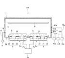
図1を参照して、SMは、本発明の成膜方法を実施することができるマグネトロン方式のスパッタリング装置である。スパッタリング装置SMは成膜室11を画成する真空チャンバ1を備える。以下においては、「上」、「下」といった方向を示す用語は、図1に示すスパッタリング装置SMの姿勢を基準にする。真空チャンバ1の側壁には排気口12が開設され、排気口12には、ロータリーポンプ、ドライポンプ、ターボ分子ポンプなどで構成される真空排気手段Pからの排気管13が接続され、成膜室11内を真空引きして所定圧力(例えば、1×10⁻⁵Pa)に保持できるようになっている。
Referring to FIG. 1, SM is a magnetron type sputtering apparatus capable of performing the film forming method of the present invention. The sputtering apparatus SM includes a
真空チャンバ1の下部には、アルミニウム製(例えば、純度99.999%)のターゲット21,22と磁石ユニット31,32とで構成される2個のカソードユニットCuが設けられている。各ターゲット21,22は、同一の略直方体形状に夫々形成されたものであり、その下面には、スパッタリングによる成膜中、当該ターゲット21,22を冷却する銅製のバッキングプレート22がインジウムなどのボンディング材(図示せず)を介して夫々接合されている。そして、バッキングプレート22に接合した状態で各ターゲット21,22が真空チャンバ1の下部内面に真空シール兼用の絶縁体23を介して設置される。この場合、各ターゲット21,22は、成膜室11の左右方向に所定の間隔を置いて、かつ、未使用時のターゲット21,22の上面が、後述の基板Sに平行な同一平面内に位置するようになっている。各ターゲット21,22には、交流電源Psからの出力Pkが夫々接続され、交流電源Psにより各ターゲット21,22間に所定周波数(例えば、1kHz〜100kHz)の交流電力が投入されるようになっている。
In the lower part of the
各バッキングプレート22の下方(真空チャンバ1の外側)に位置させて夫々配置された磁石ユニット31,32は同一の形態を有し、磁石ユニット31,32は、バッキングプレート22に平行に設けられ、磁性材料製の平板から構成される支持板31(ヨーク)を備える。支持板31上には、当該支持板31の中心線上に位置させて配置した中央磁石32と、この中央磁石32の周囲を囲うように、支持板31の上面外周に沿って環状に配置した周辺磁石33とがターゲット21,22側の極性をかえて設けられている。この場合、例えば、中央磁石32の同磁化に換算したときの体積をその周囲を囲う周辺磁石33の同磁化に換算したときの体積の和(周辺磁石:中央磁石:周辺磁石=1:2:1(図1参照))程度になるように設計される。これにより、各ターゲット21,22の上方で釣り合ったトンネル状の漏洩磁場(図示せず)が夫々形成される。中央磁石32及び周辺磁石33は、ネオジム磁石等の公知のものであり、これらの中央磁石及び周辺磁石は一体のものでも、または、所定体積の磁石片を複数列設して構成してもよい。なお、例えばターゲット21,22の利用効率を高めるために、磁石ユニット31,32に駆動手段(図示せず)を接続し、スパッタリングによる成膜中、上下方向または左右方向の少なくとも一方向に所定のストロークで往復動させるようにしてもよい。
The magnet units 3 1 and 3 2 arranged below the respective backing plates 22 (outside the vacuum chamber 1) have the same configuration, and the magnet units 3 1 and 3 2 are parallel to the
また、真空チャンバ1の側壁にはガス供給口41a,41bが開設され、ガス供給口41a,41bにはガス管42a,42bが夫々接続されている。ガス管42a,42bは、マスフローコントローラ43a,43bを介して、図示省略のアルゴン等の希ガスのガス源と、酸素ガスやオゾン等の酸素含有の反応ガスのガス源とに夫々連通し、成膜室11内に流量制御された希ガスと反応ガスとを導入できるようにしている。
上記スパッタリング装置SMにより各ターゲット21,22をスパッタリングして基板S表面に反応性スパッタリングにより酸化アルミニウム膜を成膜する場合、図外の真空搬送ロボットにより、並設した各ターゲット21,22に対向する成膜室11上部の所定位置に基板Sをセットし、成膜室11を所定圧力まで真空引きする。成膜室11が所定圧力に達すると、マスフローコントローラ43a,43bを制御して希ガス及び反応ガスを導入し、交流電源Psにより各ターゲット21,22の間に交流電力を投入する。これにより、各ターゲット21,22の上方にレーストラック状に高密度のプラズマが発生する。そして、プラズマ中の希ガスのイオンでターゲット21,22が夫々スパッタされる。これにより、ターゲット21,22から飛散したアルミニウム原子と酸素との反応生成物が基板S表面に付着、堆積して酸化アルミニウム膜が成膜される。
When sputtering the targets 2 1 and 2 2 by the sputtering apparatus SM and forming an aluminum oxide film on the surface of the substrate S by reactive sputtering, the targets 2 1 and 2 arranged in parallel by a vacuum transfer robot (not shown). The substrate S is set at a predetermined position above the
ここで、上記のようにして成膜された酸化アルミニウム膜は、通常、圧縮方向の応力を持つが、その圧縮応力が大きくなると、基板の反りが大きくなる等の問題を招来する。このため、所定の成膜レートを維持したまま、応力が所定値(例えば、±500MPa)以内の酸化アルミニウム膜を成膜することができるようにする必要がある。本実施形態では、真空チャンバ1の側壁に更にガス供給口41cを開設し、ガス供給口41cに、マスフローコントローラ43cを介在させたガス管42cを接続し、成膜室11内に流量制御された水蒸気を導入できるようにした。そして、例えばスパッタリングによる成膜時、マスフローコントローラ43cを制御して成膜室11に水蒸気を導入することとした。この場合、成膜時の成膜室11内の水蒸気の分圧が1×10⁻³Pa〜0.1Paの範囲となるようにマスフローコントローラ43cにより水蒸気の流量を制御することが好ましい。
Here, the aluminum oxide film formed as described above usually has a stress in the compression direction. However, when the compressive stress increases, problems such as an increase in the warpage of the substrate are caused. For this reason, it is necessary to be able to form an aluminum oxide film having a stress within a predetermined value (for example, ± 500 MPa) while maintaining a predetermined film formation rate. In the present embodiment, a
以上によれば、ターゲット21,22への投入電力、成膜時の希ガスと酸素ガスとの分圧(即ち、マスフローコントローラ43a,43bの制御による希ガスと反応ガスとの導入量)を変えずに水蒸気を導入することで、所定の成膜レートを維持したまま、水蒸気を導入しない場合と比較して低い応力の酸化アルミニウム膜を成膜することができる。このとき、水蒸気の分圧を1×10⁻³Pa〜0.1Paの範囲にすれば、酸化アルミニウム膜の応力を確実に低下させることができ、例えば、水蒸気の分圧が1×10⁻²Paのときには、圧縮応力を約−50MPaにできることが確認された。なお、水蒸気の分圧が1×10⁻³Paより低くなると、効果的に応力を小さくした状態で酸化アルミニウム膜を成膜することができず、また、水蒸気の分圧が0.1Paより高くなると、例えば異常放電が誘発されて酸化アルミニウム膜を成膜することができない場合がある。
According to the above, the input power to the targets 2 1 and 2 2 , the partial pressure of the rare gas and the oxygen gas at the time of film formation (that is, the introduction amount of the rare gas and the reactive gas by the control of the
以上の効果を確認するために、図1に示すスパッタリング装置SMを用い、基板Sの表面に酸化アルミニウム膜を成膜する実験を行った。先ず、比較実験として、各ターゲット21,22と基板Sとの間の距離を180mm、交流電源Psによるターゲット21,22間への投入電力(交流電力)を40kW、スパッタ時間を271秒に設定し、また、真空排気されている成膜室11内の圧力が0.5Paに保持されるように、マスフローコントローラ43a,43bを制御して希ガスとしてのアルゴンと酸素ガスとを8:2の流量比で導入した。そして、基板Sの中央において、基板S表面に成膜された酸化アルミニウム膜の成膜レートと応力を測定したところ、成膜レートは10.56nm/minであり、応力は約−1000MPa(圧縮応力)であった。なお、膜厚は、エリプソメータを用いて、また、応力は、薄膜応力測定装置を用いて夫々測定した。
In order to confirm the above effects, an experiment was performed in which an aluminum oxide film was formed on the surface of the substrate S using the sputtering apparatus SM shown in FIG. First, as a comparative experiment, the distance between the targets 2 1 and 2 2 and the substrate S is 180 mm, the input power (AC power) between the targets 2 1 and 2 2 by the AC power source Ps is 40 kW, and the sputtering time is 271. And the
次に、本発明の効果を示す実験として、スパッタ条件を上記と同様にし、成膜時、マスフローコントローラ43cを制御して水蒸気も所定の流量で導入した。この場合、水蒸気の分圧を5×10−4Pa〜1Paの範囲で変化させ、そのときの酸化アルミニウム膜の応力(MPa)の変化を図2に示す。これによれば、水蒸気を導入すると、酸化アルミニウム膜の応力が低下し、水蒸気の分圧が1×10⁻³Paのとき、酸化アルミニウム膜の応力を約−500MPa近くまで低下できたことが判る。このときの成膜レートは10.48nm/minであり、成膜レートが殆ど変化しないことが確認された。そして、水蒸気の分圧が1×10−2Paまでは、当該水蒸気の分圧に逆比例して酸化アルミニウム膜の応力がより低下し、水蒸気の分圧が1×10−2Paのときに、酸化アルミニウム膜の応力を約−50MPaにできたことが確認された。このときの成膜レートは11.00nm/minであった。更に、水蒸気の分圧を増加させると、酸化アルミニウム膜は引張方向の応力(引張応力)を持つようになり、水蒸気の分圧が0.1Paのときでも、酸化アルミニウム膜の応力を約+100MPaにできたことが確認された。このときの成膜レートは11.20nm/minであった。但し、分圧が0.1Paより高くなると、異常放電が誘発され、酸化アルミニウム膜を正常に成膜することができなかった。
Next, as an experiment showing the effect of the present invention, the sputtering conditions were the same as described above, and water vapor was also introduced at a predetermined flow rate by controlling the
以上、本発明の成膜方法の実施形態について説明したが、本発明は上記のものに限定されるものではない。上記実施形態では、スパッタリングによる成膜中、水蒸気を所定の分圧で導入する場合を例に説明したが、これに限定されるものではなく、水素ガスを所定の分圧で導入する場合にも、酸化アルミニウム膜の応力を低下できることが確認された。なお、上記実施形態では、真空チャンバ1の側壁に開設したガス供給口41a,41b,41cから希ガス、酸素ガス及び水蒸気を導入するものを例に説明したが、これに限定されるものではない。特に図示して説明しないが、例えば真空チャンバ1の底璧にガス管を貫装し、ターゲット21,22の周囲に位置するガス管の先端から、希ガス、酸素ガスや水蒸気を噴出するようにしてもよい。
Although the embodiments of the film forming method of the present invention have been described above, the present invention is not limited to the above. In the above embodiment, the case where water vapor is introduced at a predetermined partial pressure during film formation by sputtering has been described as an example. However, the present invention is not limited to this, and the case where hydrogen gas is introduced at a predetermined partial pressure is also described. It was confirmed that the stress of the aluminum oxide film can be reduced. In the above embodiment, the case where the rare gas, the oxygen gas, and the water vapor are introduced from the
また、上記実施形態でも、ターゲット21,22をアルミニウム製としたものを例に説明したが、ターゲット21,22を酸化アルミニウム製として、希ガスのみ、または、希ガスに加えて酸素を導入しながら、高周波電力を投入してターゲット21,22をスパッタリングし、成膜する場合にも本発明は適用できる。更に、複数枚のターゲット21,22を並設し、対をなすものに交流電源Psにより交流電力を投入するものを例に説明したが、これに限定されるものではなく、ターゲットを一枚とし、DC電源にて直流電力を投入するような場合にも本発明は適用し得る。更に、上記実施形態では、被成膜物をガラス基板とした場合を例に説明したが、例えば被成膜物を樹脂製の基材としてもよい。この場合、シート状の基材を駆動ローラと巻取りローラとの間で一定の速度で移動させながら基材の片面にスパッタリングにより酸化アルミニウム膜を成膜するようなものにも本発明は適用できる。 In the above embodiment, the target 2 1 , 2 2 is made of aluminum. However, the target 2 1 , 2 2 is made of aluminum oxide, and only the rare gas or oxygen added to the rare gas is used. The present invention can also be applied to the case where the target 2 1 , 2 2 is sputtered by forming a film while introducing high frequency power. Furthermore, the description has been given by taking as an example the case where a plurality of targets 2 1 and 2 2 are arranged side by side and AC power is supplied to the pair of targets by the AC power supply Ps, but the present invention is not limited to this, and the targets are not limited. The present invention can also be applied to a case in which DC power is supplied from a DC power source. Furthermore, although the said embodiment demonstrated to the example the case where a film-forming thing was used as the glass substrate, it is good also considering a film-forming thing as a resin-made base material, for example. In this case, the present invention can also be applied to an apparatus in which an aluminum oxide film is formed on one surface of a base material by sputtering while moving the sheet-like base material at a constant speed between a driving roller and a take-up roller. .
SM…スパッタリング装置、1…真空チャンバ、21,22…ターゲット、42a…ガス管(希ガス用)、43a…マスフローコントローラ(希ガス用)、42b…ガス管(反応ガス用)、43b…マスフローコントローラ(反応ガス用)、42c…ガス管(水蒸気用)、43c…マスフローコントローラ(水蒸気用)、S…基板(被成膜物)。 SM ... Sputtering device, 1 ... Vacuum chamber, 2 1 , 2 2 ... Target, 42a ... Gas pipe (for rare gas), 43a ... Mass flow controller (for rare gas), 42b ... Gas pipe (for reactive gas), 43b ... Mass flow controller (for reaction gas), 42c ... gas pipe (for water vapor), 43c ... mass flow controller (for water vapor), S ... substrate (film formation).
上記課題を解決するために、本発明は、真空チャンバ内に被成膜物と、アルミニウム製または酸化アルミニウム製のターゲットとを配置し、真空雰囲気中の真空チャンバ内に希ガス及び酸素含有の反応ガスまたは希ガスのみを導入し、ターゲットに所定電力を投入してターゲットをスパッタリングすることで被成膜物の表面に酸化アルミニウム膜を成膜する成膜方法において、真空チャンバ内に水素ガスまたは水蒸気を導入し、スパッタリングによる成膜時、真空チャンバ内に水蒸気が所定の分圧で存在する状態とし、応力が所定値以内の酸化アルミニウム膜を得ることを特徴とする。この場合、前記水蒸気の分圧を2×10 −3 Pa〜0.1Paの範囲にすることがより好ましい。また、真空チャンバ内に、前記ターゲットの少なくとも2枚を設け、対をなすターゲット間に所定周波数の交流電力を投入して各ターゲットをスパッタリングすることが好ましい。
In order to solve the above-described problems, the present invention provides a deposition object and an aluminum or aluminum oxide target in a vacuum chamber, and a reaction containing a rare gas and oxygen in the vacuum chamber in a vacuum atmosphere. In a film formation method for forming an aluminum oxide film on the surface of an object to be deposited by introducing only a gas or a rare gas, applying a predetermined power to the target, and sputtering the target, hydrogen gas or water vapor is placed in a vacuum chamber. When forming a film by sputtering, water vapor is present in the vacuum chamber at a predetermined partial pressure, and an aluminum oxide film having a stress within a predetermined value is obtained . In this case, it is more preferable that the partial pressure of the water vapor is in the range of 2 × 10 −3 Pa to 0.1 Pa. Preferably, at least two of the targets are provided in a vacuum chamber, and each target is sputtered by supplying AC power of a predetermined frequency between the paired targets.
Claims (2)
真空チャンバ内に水素ガスまたは水蒸気を導入することを特徴とする成膜方法。 An object to be deposited and a target made of aluminum or aluminum oxide are placed in a vacuum chamber, and only a rare gas and an oxygen-containing reactive gas or a rare gas are introduced into the vacuum chamber in a vacuum atmosphere, and a predetermined target is applied to the target. In a film formation method for forming an aluminum oxide film on the surface of an object to be deposited by applying power and sputtering a target,
A film forming method, wherein hydrogen gas or water vapor is introduced into a vacuum chamber.
前記スパッタリングによる成膜時、真空チャンバ内の前記水蒸気の分圧を1×10⁻³Pa〜0.1Paの範囲にしたことを特徴とする請求項1記載の成膜方法。 The film forming method according to claim 1, wherein water vapor is introduced into the vacuum chamber.
The film forming method according to claim 1, wherein the partial pressure of the water vapor in the vacuum chamber is set to a range of 1 × 10 −3 Pa to 0.1 Pa during the film formation by sputtering.
Priority Applications (5)
| Application Number | Priority Date | Filing Date | Title |
|---|---|---|---|
| JP2016124478A JP6322669B2 (en) | 2016-06-23 | 2016-06-23 | Stress adjustment method |
| PCT/JP2017/020216 WO2017221650A1 (en) | 2016-06-23 | 2017-05-31 | Film formation method |
| CN201780038184.2A CN109328243A (en) | 2016-06-23 | 2017-05-31 | Film build method |
| KR1020187026465A KR20180115731A (en) | 2016-06-23 | 2017-05-31 | Stress adjustment method |
| TW106119666A TWI686489B (en) | 2016-06-23 | 2017-06-13 | Stress adjustment method |
Applications Claiming Priority (1)
| Application Number | Priority Date | Filing Date | Title |
|---|---|---|---|
| JP2016124478A JP6322669B2 (en) | 2016-06-23 | 2016-06-23 | Stress adjustment method |
Publications (2)
| Publication Number | Publication Date |
|---|---|
| JP2017226887A true JP2017226887A (en) | 2017-12-28 |
| JP6322669B2 JP6322669B2 (en) | 2018-05-09 |
Family
ID=60784678
Family Applications (1)
| Application Number | Title | Priority Date | Filing Date |
|---|---|---|---|
| JP2016124478A Active JP6322669B2 (en) | 2016-06-23 | 2016-06-23 | Stress adjustment method |
Country Status (5)
| Country | Link |
|---|---|
| JP (1) | JP6322669B2 (en) |
| KR (1) | KR20180115731A (en) |
| CN (1) | CN109328243A (en) |
| TW (1) | TWI686489B (en) |
| WO (1) | WO2017221650A1 (en) |
Families Citing this family (1)
| Publication number | Priority date | Publication date | Assignee | Title |
|---|---|---|---|---|
| WO2022059277A1 (en) * | 2020-09-16 | 2022-03-24 | 株式会社アルバック | Laminated structure, and method for manufacturing laminated structure |
Citations (8)
| Publication number | Priority date | Publication date | Assignee | Title |
|---|---|---|---|---|
| JPH0364451A (en) * | 1989-07-31 | 1991-03-19 | Sharp Corp | Production of insulation coating film |
| JPH06248420A (en) * | 1993-02-25 | 1994-09-06 | Kyocera Corp | Hard film coated member |
| JPH0770749A (en) * | 1993-09-03 | 1995-03-14 | Canon Inc | Formation of thin film and device therefor |
| JPH0925571A (en) * | 1995-07-06 | 1997-01-28 | Canon Inc | Film formation of oxide thin film |
| JPH0995773A (en) * | 1995-10-03 | 1997-04-08 | Kobe Steel Ltd | Production of window material for vacuum device |
| JP2002030432A (en) * | 2000-07-19 | 2002-01-31 | Hitachi Ltd | System and method for sputtering |
| JP2005138208A (en) * | 2003-11-05 | 2005-06-02 | Sumitomo Electric Hardmetal Corp | Surface coated cutting tool and its manufacturing method |
| JP2014141698A (en) * | 2013-01-23 | 2014-08-07 | Dainippon Screen Mfg Co Ltd | Film deposition method for aluminium oxide |
Family Cites Families (4)
| Publication number | Priority date | Publication date | Assignee | Title |
|---|---|---|---|---|
| US5911856A (en) * | 1993-09-03 | 1999-06-15 | Canon Kabushiki Kaisha | Method for forming thin film |
| KR100691168B1 (en) * | 2003-02-27 | 2007-03-09 | 섬모픽스, 인코포레이티드 | Dielectric barrier layer films |
| WO2006005067A2 (en) * | 2004-07-07 | 2006-01-12 | General Electric Company | Protective coating on a substrate and method of making thereof |
| CN104480442A (en) * | 2014-12-05 | 2015-04-01 | 中国科学院电工研究所 | Method for preparing transparent conductive film containing aluminum zinc hydroxide |
-
2016
- 2016-06-23 JP JP2016124478A patent/JP6322669B2/en active Active
-
2017
- 2017-05-31 KR KR1020187026465A patent/KR20180115731A/en not_active Application Discontinuation
- 2017-05-31 CN CN201780038184.2A patent/CN109328243A/en active Pending
- 2017-05-31 WO PCT/JP2017/020216 patent/WO2017221650A1/en active Application Filing
- 2017-06-13 TW TW106119666A patent/TWI686489B/en active
Patent Citations (8)
| Publication number | Priority date | Publication date | Assignee | Title |
|---|---|---|---|---|
| JPH0364451A (en) * | 1989-07-31 | 1991-03-19 | Sharp Corp | Production of insulation coating film |
| JPH06248420A (en) * | 1993-02-25 | 1994-09-06 | Kyocera Corp | Hard film coated member |
| JPH0770749A (en) * | 1993-09-03 | 1995-03-14 | Canon Inc | Formation of thin film and device therefor |
| JPH0925571A (en) * | 1995-07-06 | 1997-01-28 | Canon Inc | Film formation of oxide thin film |
| JPH0995773A (en) * | 1995-10-03 | 1997-04-08 | Kobe Steel Ltd | Production of window material for vacuum device |
| JP2002030432A (en) * | 2000-07-19 | 2002-01-31 | Hitachi Ltd | System and method for sputtering |
| JP2005138208A (en) * | 2003-11-05 | 2005-06-02 | Sumitomo Electric Hardmetal Corp | Surface coated cutting tool and its manufacturing method |
| JP2014141698A (en) * | 2013-01-23 | 2014-08-07 | Dainippon Screen Mfg Co Ltd | Film deposition method for aluminium oxide |
Also Published As
| Publication number | Publication date |
|---|---|
| TWI686489B (en) | 2020-03-01 |
| JP6322669B2 (en) | 2018-05-09 |
| TW201816150A (en) | 2018-05-01 |
| WO2017221650A1 (en) | 2017-12-28 |
| CN109328243A (en) | 2019-02-12 |
| KR20180115731A (en) | 2018-10-23 |
Similar Documents
| Publication | Publication Date | Title |
|---|---|---|
| JP5875462B2 (en) | Sputtering method | |
| JP6559233B2 (en) | Magnetron sputtering equipment | |
| KR20080064125A (en) | Spattering and film forming method | |
| US20170004995A1 (en) | Film Forming Apparatus and Film Forming Method | |
| JP5527894B2 (en) | Sputtering equipment | |
| JP2010013724A (en) | Penning type sputtering system | |
| JP5186152B2 (en) | Thin film formation method | |
| JP5718767B2 (en) | Sputtering equipment | |
| JP6322669B2 (en) | Stress adjustment method | |
| JP2014148703A (en) | Sputtering device | |
| JP2010248576A (en) | Magnetron sputtering apparatus | |
| JP6887230B2 (en) | Film formation method | |
| JP6734711B2 (en) | Deposition method | |
| JP2013001943A (en) | Sputtering apparatus | |
| JP2012062573A (en) | Discharge electrode and discharge method | |
| WO2019163439A1 (en) | Film formation method | |
| JP2009046714A (en) | Film deposition system and film deposition method | |
| JP2004124171A (en) | Plasma processing apparatus and method | |
| JP7219140B2 (en) | Deposition method | |
| KR102376098B1 (en) | film formation method | |
| JP2018204061A (en) | Sputtering apparatus | |
| JP2017115215A (en) | Manufacturing apparatus for organic el display device | |
| JP5475843B2 (en) | Film formation method, film formation apparatus, piezoelectric film, piezoelectric element, and liquid ejection apparatus | |
| JP2013194300A (en) | Sputtering apparatus | |
| JP2020143356A (en) | Sputtering apparatus and sputtering method |
Legal Events
| Date | Code | Title | Description |
|---|---|---|---|
| A131 | Notification of reasons for refusal |
Free format text: JAPANESE INTERMEDIATE CODE: A131 Effective date: 20171128 |
|
| A521 | Request for written amendment filed |
Free format text: JAPANESE INTERMEDIATE CODE: A523 Effective date: 20180111 |
|
| TRDD | Decision of grant or rejection written | ||
| A01 | Written decision to grant a patent or to grant a registration (utility model) |
Free format text: JAPANESE INTERMEDIATE CODE: A01 Effective date: 20180327 |
|
| A61 | First payment of annual fees (during grant procedure) |
Free format text: JAPANESE INTERMEDIATE CODE: A61 Effective date: 20180409 |
|
| R150 | Certificate of patent or registration of utility model |
Ref document number: 6322669 Country of ref document: JP Free format text: JAPANESE INTERMEDIATE CODE: R150 |
|
| R250 | Receipt of annual fees |
Free format text: JAPANESE INTERMEDIATE CODE: R250 |
|
| R250 | Receipt of annual fees |
Free format text: JAPANESE INTERMEDIATE CODE: R250 |
|
| R250 | Receipt of annual fees |
Free format text: JAPANESE INTERMEDIATE CODE: R250 |
|
| R250 | Receipt of annual fees |
Free format text: JAPANESE INTERMEDIATE CODE: R250 |