JP2017226491A - Sheet material transport unit, sheet material transport device and device for discharging liquid - Google Patents
Sheet material transport unit, sheet material transport device and device for discharging liquid Download PDFInfo
- Publication number
- JP2017226491A JP2017226491A JP2016121729A JP2016121729A JP2017226491A JP 2017226491 A JP2017226491 A JP 2017226491A JP 2016121729 A JP2016121729 A JP 2016121729A JP 2016121729 A JP2016121729 A JP 2016121729A JP 2017226491 A JP2017226491 A JP 2017226491A
- Authority
- JP
- Japan
- Prior art keywords
- suction
- sheet material
- plate
- drum
- groove
- Prior art date
- Legal status (The legal status is an assumption and is not a legal conclusion. Google has not performed a legal analysis and makes no representation as to the accuracy of the status listed.)
- Pending
Links
Images


Abstract
Description
本発明は、シート材搬送ユニット、シート材搬送装置及び液体を吐出する装置に関する。 The present invention relates to a sheet material conveyance unit, a sheet material conveyance device, and a device for discharging a liquid.
従来、用紙等の記録媒体を搬送ドラムに固定して、搬送ドラムの外周面に近接して配置された記録ヘッドから記録媒体に向かってインクを吐出して画像を形成するインクジェット記録装置が知られている。
搬送ドラムへの用紙の固定方法としては、エアー吸引方式が知られている。この方式では、搬送ドラムの表面に複数の吸引穴を有する薄肉の吸引プレートを巻き付けるように密着させる構成となっている。搬送ドラムの内部をエアーポンプで吸引すると、搬送ドラムの表面に設けられたドラム吸引溝に連通する吸引プレートの吸引穴が負圧となり、用紙は吸引プレートに吸着される。
2. Description of the Related Art Conventionally, there is known an ink jet recording apparatus that forms an image by fixing a recording medium such as paper to a conveyance drum and ejecting ink from a recording head arranged close to the outer peripheral surface of the conveyance drum toward the recording medium. ing.
An air suction method is known as a method for fixing the paper to the transport drum. In this system, a thin suction plate having a plurality of suction holes is wound around the surface of the conveying drum so as to be wound around. When the inside of the transport drum is sucked by the air pump, the suction hole of the suction plate communicating with the drum suction groove provided on the surface of the transport drum becomes negative pressure, and the sheet is adsorbed by the suction plate.
しかしながら、エアー吸引力が不足すると用紙が搬送ドラムの表面から離れる「浮き」という現象が発生する。浮きは、インクジェット方式で重要な用紙とヘッドとの間のギャップが各ヘッド間で大きく変動することにつながり、所望の画像が得られない懸念がある。ヘッド間ギャップの変動はインク滴の着弾位置精度に影響するからである。
浮きの例としては、小サイズの用紙の場合に塞がれない吸引穴からのエアー漏れによる吸引力低下によるものが挙げられる。また、厚みの大きい用紙のコシ力が大きいことに起因する用紙端部(搬送ドラムの回転方向における先端部や後端部)の浮きなどが挙げられる。
However, if the air suction force is insufficient, a phenomenon of “floating” in which the paper is separated from the surface of the transport drum occurs. There is a concern that the gap between the paper and the head, which is important in the ink jet method, greatly fluctuates between the heads, and a desired image cannot be obtained. This is because the variation in the gap between the heads affects the landing position accuracy of the ink droplets.
As an example of the float, there is a case in which the suction force is reduced due to air leakage from a suction hole that is not blocked in the case of a small-size sheet. Further, there is a lifting of a paper edge (a leading edge or a trailing edge in the rotation direction of the transport drum) due to the large stiffness of the thick paper.
ヘッド間ギャップの変動につながる浮きを抑制するため、従来より様々な工夫がされている。
搬送ドラムの外周面にエアーポンプからのエアー吸引経路となる溝を複数本配置し、その外周に吸引プレートを一枚巻く構成が記載されている(例えば、特許文献1参照)。吸引プレートには搬送ドラムの溝と接続するプレート溝や吸引穴が設けられ、ハーフエッチング加工で製作されている。
プレート溝には流量を制限する絞り部が設けられており、この絞り部は用紙吸着位置に応じて形状を変えている。特に大きな吸引力を必要とする用紙後端部に対応する部位では、流量を大きくして吸引力を大きくする狙いから、他の領域よりも大きい絞り部を設ける構成となっている。
Various devices have been devised in the past in order to suppress floating that leads to fluctuations in the gap between the heads.
A configuration is described in which a plurality of grooves serving as air suction paths from the air pump are arranged on the outer peripheral surface of the transport drum, and a single suction plate is wound around the outer periphery (see, for example, Patent Document 1). The suction plate is provided with plate grooves and suction holes connected to the grooves of the transport drum, and is manufactured by half-etching.
The plate groove is provided with a restricting portion for restricting the flow rate, and the restricting portion changes its shape according to the sheet suction position. In particular, a portion corresponding to the rear end portion of the sheet that requires a large suction force is configured to have a throttle portion that is larger than other regions in order to increase the suction force by increasing the flow rate.
しかしながら、特許文献1に記載の構成では、搬送ドラムの溝とプレート溝との接続箇所に絞り部がある。換言すれば、吸引穴から離れた位置に絞り部がある。このため、用紙サイズが小さくなって塞がれない吸引穴が存在する場合に、開放された吸引穴からプレート溝へ外部空気が流入することに対する絞り部の抵抗が低い。これにより、用紙を吸着するための負圧が小さくなり、用紙の周囲部(先端部、後端部、側端部、角部等)の特に開放された吸引穴近傍で吸引力が低下し、浮きが生じやすいという問題があった。
However, in the configuration described in
本発明は、このような現状に鑑みてなされたもので、記録媒体の浮きを高精度に抑制できるシート材搬送ユニットの提供を目的とする。 SUMMARY An advantage of some aspects of the invention is that it provides a sheet material conveyance unit capable of suppressing the floating of a recording medium with high accuracy.
上記目的を達成するために、本発明のシート材搬送ユニットは、エアー吸引路を有するドラム状の搬送体と、吸引穴を複数有して前記搬送体の表面に巻き付けるように装着され、シート材を前記搬送体の表面形状に沿うように吸着するための吸引部材と、
を備え、前記吸引部材の前記吸引穴と反対側には、前記エアー吸引路と前記吸引穴とを連通させる吸引溝が複数形成され、前記吸引穴から外部空気が流入する際に、流入方向における前記吸引溝よりも上流側に流入抵抗部が存在する。
In order to achieve the above object, a sheet material conveyance unit of the present invention has a drum-shaped conveyance body having an air suction path, a plurality of suction holes, and is mounted so as to be wound around the surface of the conveyance body. A suction member for adsorbing so as to conform to the surface shape of the carrier,
A plurality of suction grooves that connect the air suction path and the suction holes are formed on the side opposite to the suction holes of the suction member, and when external air flows in from the suction holes, An inflow resistance portion exists on the upstream side of the suction groove.
本発明によれば、記録媒体の浮きを高精度に抑制できるシート材搬送ユニットを提供できる。 ADVANTAGE OF THE INVENTION According to this invention, the sheet | seat material conveyance unit which can suppress the floating of a recording medium with high precision can be provided.
以下、本発明の実施形態を図を参照して説明する。
まず、図1乃至図7に基づいて第1の実施形態を説明する。図1は、液体を吐出する装置としてのインクジェット記録装置の全体構成図である。
インクジェット記録装置1は、記録媒体としての用紙2が積層して収容された給紙部3と、インク滴の吐出による画像形成部としての印字部4と、インク画像を乾燥させる乾燥部5と、画像形成後の用紙2が排出されてスタックされる排出部6とを有している。
本実施形態では、給紙部3、印字部4、排出部6をそれぞれキャスター付きの分離可能な構成とし、これらを組み合わせてインクジェット記録装置1をシステムとして構成している。この構成に限らず、インクジェット記録装置1全体を一体不可分の構成としてもよい。
Embodiments of the present invention will be described below with reference to the drawings.
First, a first embodiment will be described with reference to FIGS. FIG. 1 is an overall configuration diagram of an ink jet recording apparatus as an apparatus for ejecting liquid.
The ink
In the present embodiment, the
印字部4には、給紙部3から給紙された用紙2を周面に吸着して搬送するシート材搬送ユニット7と、液体吐出ヘッドとしての記録ヘッド8とが設けられている。
記録ヘッド8は、イエローのインクを吐出する記録ヘッド8Yと、マゼンタのインクを吐出する記録ヘッド8Mと、シアンのインクを吐出する記録ヘッド8Cと、黒のインクを吐出する記録ヘッド8Bkとを有し、これらはシート材搬送ユニット7の周面に沿って配置されている。
記録ヘッド8は、用紙2の搬送方向と直交する幅方向における画像形成領域の最大幅に対応する長さを有するフルライン型の記録ヘッドである。
The printing unit 4 is provided with a sheet material conveyance unit 7 that adsorbs and conveys the
The recording head 8 includes a recording head 8Y that discharges yellow ink, a
The recording head 8 is a full-line recording head having a length corresponding to the maximum width of the image forming area in the width direction orthogonal to the conveyance direction of the
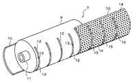
図2に示すように、シート材搬送ユニット7は、ドラム状の搬送体としての搬送ドラム9と、搬送ドラム9の表面に巻き付けるように装着され、用紙2を搬送ドラム9の表面形状に沿うように吸着するための吸引部材としての吸引プレート10とを有している。
搬送ドラム9は長手方向(軸方向)の両端に回転軸11を有しているとともに、外周面に複数のエアー吸引路としてのドラム吸引溝12を有している。
ドラム吸引溝12は搬送ドラム9の周方向に沿って形成され、その周方向端部には、図3に示すように、搬送ドラム9の内部に連通する接続穴13が形成されている。図2に示すように、吸引プレート10は多数の小さな吸引穴14を有し、搬送ドラム9の周面に沿った形状を有している。
As shown in FIG. 2, the sheet material conveyance unit 7 is mounted so as to be wound around the surface of the conveyance drum 9 and the conveyance drum 9 as a drum-shaped conveyance body so that the
The transport drum 9 has rotating
The
吸引プレート10は、1枚又は2枚の分割構成を有し、搬送ドラム9の外面に設けられるグリップ手段(省略)で周方向の先端部を止められて固定される。
ドラム吸引溝12やグリップ手段は、例えば特許文献1に記載の構成を採用できる。
The
As the
図2において、符号15は吸引プレート10における非開口部を示し、吸引穴14が存在しない非開口部15は搬送ドラム9のドラム吸引溝12の部位を塞ぐように配置されている。
図4は吸引プレート10を搬送ドラム9に装着した状態を示している。
搬送ドラム9の内部には、接続穴13に連通する吸引用流路が設けられている。該吸引用流路は、搬送ドラム9の側面に設けられた配管やジョイント及び搬送ドラム9の回転軸11の内部に設けられた流路を介して、搬送ドラム9の外部に設けられたエアーポンプ等の吸引手段に接続されている。
エアーポンプを動作させて負圧を発生させると、吸引穴14を介して用紙2が吸引プレート10の表面に吸着されて保持される。
In FIG. 2,
FIG. 4 shows a state where the
A suction flow path communicating with the
When a negative pressure is generated by operating the air pump, the
シート材搬送ユニット7とエアーポンプ等の吸引手段とによりシート材搬送装置が構成される。 A sheet material conveying apparatus is configured by the sheet material conveying unit 7 and suction means such as an air pump.
図5に示すように、吸引プレート10は、ドラム吸引溝12に連通する吸引溝としての複数のプレート吸引溝16が形成された下層プレート17と、吸引穴14が形成された上層プレート18と、下層プレート17と上層プレート18との間に配置された流入抵抗部としての通気性を有する多孔体19とを積層した構成となっている。
吸引プレート10は、プレート吸引溝16の長手方向が搬送ドラム9のドラム吸引溝12の長手方向と直交するように搬送ドラム9に装着される。
多孔体19としては、例えば、フェルト材、スポンジ材、フィルタ材などを採用することができる。
As shown in FIG. 5, the
The
As the
図6に示すように、小さいサイズの用紙2を吸着する場合、用紙2で塞がれる吸引穴4aに対し塞がれずに開放される吸引穴4bが存在する。外部に開放された吸引穴4bから気流20が流入すると、吸引プレート10のプレート吸引溝16内の負圧が低下し、用紙2の端部に浮きを発生させる要因となる。
特許文献1では、上記のようにドラム吸引溝とプレート吸引溝との接続箇所においてプレート吸引溝に絞り部を設けて流入抵抗を得る構成としている。しかしながら、絞り部と開口した吸引穴との間が離れているため、絞り部の流体抵抗作用が発揮される前にプレート吸引溝に気流が流入して負圧低下を来たすこととなる。
As shown in FIG. 6, when a small-
In
これに対し、本実施形態では、開放された吸引穴4bからの外部空気による気流20の流入方向において、プレート吸引溝16よりも上流側に多孔体19が存在する。このため、開放された吸引穴4bから流入する気流20は、プレート吸引溝16に入り込む前に多孔体19を通過するため、ここで流体抵抗が生じ、プレート吸引溝16の負圧低下が抑制される。
プレート吸引溝16の負圧低下が抑制されるので、用紙2で塞がれた吸引穴4aの吸引力も殆ど低下しない。このため、開口した吸引穴4bに近い用紙2の端部の浮きが抑制される。
本実施形態では吸引プレート10を、2枚のプレートと多孔体19とを重ねて構成したが、多孔体構造を下層プレート17と上層プレート18のうち少なくとも一方にハーフエッチング加工等により一体に形成してもよい。
On the other hand, in this embodiment, the
Since the negative pressure drop of the
In the present embodiment, the
本発明と従来例(特許文献1)との違いを、図7に基づいて、ドレイン溝(ドラム吸引溝12)内の負圧と風量との関係から模式的に説明する。
A点は、サイズの大きい用紙の場合で、全ての吸引穴が塞がれている状態である。この場合には流路抵抗が大きいので、本発明、従来例共に差はない。
用紙サイズが小さくなって吸引穴の一部が開放されると、従来例では絞り部が吸引穴から離れているので、流路抵抗が低い。このためドレイン溝内に入り込む風量が大きくなり、ドレイン溝内の負圧は目標値を下回るB点レベルとなる。
本発明では、吸引穴の近傍に位置する多孔体により流路抵抗を大きくしているので、用紙サイズが小さくなって吸引穴の一部が開放されても目標値を上回るC点レベルの負圧を確保することができる。
The difference between the present invention and the conventional example (Patent Document 1) will be schematically described based on the relationship between the negative pressure in the drain groove (drum suction groove 12) and the air volume based on FIG.
Point A is a large size paper, and is a state where all the suction holes are closed. In this case, since the flow path resistance is large, there is no difference between the present invention and the conventional example.
When the paper size is reduced and a part of the suction hole is opened, the flow path resistance is low because the throttle portion is separated from the suction hole in the conventional example. For this reason, the air volume entering the drain groove is increased, and the negative pressure in the drain groove is at a point B level lower than the target value.
In the present invention, since the flow path resistance is increased by the porous body located in the vicinity of the suction hole, even if the paper size is reduced and a part of the suction hole is opened, the negative pressure at the C point level exceeding the target value. Can be secured.
上記のように、本実施形態によれば、浮きを高精度に抑制できるとともに、さまざまなサイズの用紙や厚紙への対応が可能となる。
特に、より剛性の大きくコシの強い記録媒体(厚紙)を搬送ドラムに吸引することができ、用紙対応力の向上につながる。また大きな吸引力を必要とする用紙後端の吸引力を改善して浮きを抑え、ヘッド間ギャップの安定による着弾位置精度の向上に寄与することができる。
ヘッド間ギャップの変動を高精度に抑制できるので、画質向上を図ることができる。
As described above, according to the present embodiment, the floating can be suppressed with high accuracy, and various sizes of paper and cardboard can be handled.
In particular, a recording medium (thick paper) that is stiffer and stronger can be sucked to the transport drum, leading to an improvement in paper handling capability. In addition, it is possible to improve the suction force at the trailing edge of the sheet, which requires a large suction force, to suppress floating, and to contribute to the improvement of the landing position accuracy by stabilizing the gap between the heads.
Since fluctuations in the gap between the heads can be suppressed with high accuracy, the image quality can be improved.
図8乃至図13に基づいて、第2の実施形態を説明する。
上記実施形態と同一部分は同一符号で示し、既にした構成上及び機能上の説明は省略して要部のみ説明する。
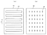
図8は本実施形態における吸引部材としての吸引プレート22を搬送ドラム9への装着面と反対側から見た平面図である。
吸引プレート22は、搬送ドラム9への装着面側に複数の吸引溝としてのプレート吸引溝23を有し、表面側には複数の矩形状の吸引穴24を有している。各プレート吸引溝23は矢印Fで示す搬送ドラム9の回転方向と直交する方向に延びている。
The second embodiment will be described with reference to FIGS.
The same parts as those of the above-described embodiment are denoted by the same reference numerals, and the description of the configuration and functions already described is omitted, and only the main parts will be described.
FIG. 8 is a plan view of the
The
図9に示すように、吸引プレート22は、プレート吸引溝23が複数形成された下層プレート25と、複数の吸引穴24が形成された上層プレート26とを重ね合わせた構成である。ハーフエッチング加工等により、1枚のプレートにプレート吸引溝23と吸引穴24を形成してもよい。
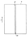
図10に示すように、搬送ドラム9の表面には、搬送ドラム9の回転方向に平行にエアー吸引路としてのドラム吸引溝27が形成され、ドラム吸引溝27の一端部には吸引手段への接続穴28が形成されている。接続穴28は上記実施形態における接続穴13と同様の目的で形成されている。
As shown in FIG. 9, the
As shown in FIG. 10, a
図11は、吸引プレート22を搬送ドラム9の表面に装着した状態の平面展開図である。ドラム吸引溝27を接続穴28を介して吸引手段により吸引すると、ドラム吸引溝27に連通したプレート吸引溝23が負圧となり、プレート吸引溝23に連通した吸引穴24により用紙2が吸着される。
FIG. 11 is a plan development view showing a state in which the
本実施形態では、流入抵抗部が吸引穴24自体であり、吸引穴24の矩形形状により流入抵抗作用が発現する。
吸引穴24の縦横比が大きければ、面積に対して吸引穴24の外周が長くなるため、通風抵抗が大きくなり、流量が制限される。
図12は、吸引穴の縦横比と流量との関係を実験により調べた結果である。横軸は吸引穴の縦横比を対数表示で表しており、縦軸は吸引穴を通過する流量を表している。
なお、吸引穴面積は固定である。
In this embodiment, the inflow resistance portion is the
If the aspect ratio of the
FIG. 12 shows the result of an experiment examining the relationship between the aspect ratio of the suction hole and the flow rate. The horizontal axis represents the aspect ratio of the suction hole in logarithmic display, and the vertical axis represents the flow rate passing through the suction hole.
The suction hole area is fixed.
図12から、縦横比を10以上にすると通風抵抗が大きくなことが分かる。従って、吸引穴24を縦横比10以上の形状とすることで、開放された吸引穴24を通過する空気の流量を減らすことができ、負圧低下を抑制することができる。
図13に示すように、吸引プレート22のプレート吸引溝23をジグザグ形状にし、該形状に沿って吸引穴24を千鳥状に配置してもよい。
このようにすれば、用紙2で塞がれずに開放された吸引穴24から流入する空気はプレート吸引溝23がストレートな場合に比べて流れが阻害されるので、吸引穴24の形状による通風抵抗と相まって、負圧低下の抑制機能をさらに高めることができる。
FIG. 12 shows that the ventilation resistance increases when the aspect ratio is 10 or more. Therefore, when the
As shown in FIG. 13, the
In this way, air flowing from the
本実施形態では、プレート吸引溝23の流量を大きくしつつ吸引穴24の流入抵抗を大きくできるので、用紙の吸引力を大きくして浮きを高精度に抑制できるとともに、さまざまなサイズの用紙や厚紙への対応が可能となる。すなわち、用紙対応力の向上を図ることができる。
ヘッド間ギャップの変動を高精度に抑制できるので、画質向上を図ることができる。
また、吸引穴の形状のみで浮き抑制に対応できるため、吸引プレートの構成の簡易化、ひいては製造コストの低減にも寄与できる。
In the present embodiment, since the inflow resistance of the
Since fluctuations in the gap between the heads can be suppressed with high accuracy, the image quality can be improved.
In addition, since it is possible to cope with floating suppression only by the shape of the suction hole, it is possible to contribute to simplification of the configuration of the suction plate, and thus reduction of manufacturing cost.
上記実施形態では、シート材の一例として用紙(記録媒体)を例示したが、本発明はこれに限定されず、OHP(オーバーヘッドプロジェクタ)用フィルムや銅箔等のシート状で搬送ドラムの形状に沿って吸着・搬送可能なシート材全てを対象とすることができる。
また、インク以外の液体を吐出する装置にも同様に実施することができる。
In the above embodiment, a sheet (recording medium) is illustrated as an example of a sheet material, but the present invention is not limited to this, and is in the form of a sheet for an OHP (overhead projector) film or copper foil and follows the shape of the transport drum. Thus, all sheet materials that can be sucked and conveyed can be targeted.
Further, the present invention can be similarly applied to an apparatus that discharges liquid other than ink.
以上、本発明の好ましい実施の形態について説明したが、本発明はかかる特定の実施形態に限定されるものではなく、上述の説明で特に限定しない限り、特許請求の範囲に記載された本発明の趣旨の範囲内において、種々の変形・変更が可能である。
本発明の実施の形態に記載された効果は、本発明から生じる最も好適な効果を例示したに過ぎず、本発明による効果は、本発明の実施の形態に記載されたものに限定されるものではない。
The preferred embodiments of the present invention have been described above. However, the present invention is not limited to such specific embodiments, and unless specifically limited by the above description, the present invention described in the claims is not limited. Various modifications and changes are possible within the scope of the gist.
The effects described in the embodiments of the present invention are merely examples of the most preferable effects resulting from the present invention, and the effects of the present invention are limited to those described in the embodiments of the present invention. is not.
1 液体を吐出する装置としてのインクジェット記録装置
2 記録媒体としての用紙
7 シート材搬送ユニット
9 搬送体としての搬送ドラム
10、22 吸引プレート
12、27 エアー吸引路としてのドラム吸引溝
14、24 吸引穴
19 多孔体
23 吸引溝としてのプレート吸引溝
DESCRIPTION OF
Claims (7)
吸引穴を複数有して前記搬送体の表面に巻き付けるように装着され、シート材を前記搬送体の表面形状に沿うように吸着するための吸引部材と、
を備え、
前記吸引部材の前記吸引穴と反対側には、前記エアー吸引路と前記吸引穴とを連通させる吸引溝が複数形成され、
前記吸引穴から外部空気が流入する際に、流入方向における前記吸引溝よりも上流側に流入抵抗部が存在するシート材搬送ユニット。 A drum-shaped transport body having an air suction path;
A suction member that has a plurality of suction holes and is wound around the surface of the transport body, and sucks the sheet material along the surface shape of the transport body;
With
On the opposite side of the suction member from the suction hole, a plurality of suction grooves that connect the air suction path and the suction hole are formed,
A sheet material transport unit in which an inflow resistance portion exists on the upstream side of the suction groove in the inflow direction when external air flows from the suction hole.
前記流入抵抗部が、前記吸引穴と前記吸引溝との間に設けられた多孔体であるシート材搬送ユニット。 In the sheet material conveyance unit according to claim 1,
The sheet material conveyance unit, wherein the inflow resistance portion is a porous body provided between the suction hole and the suction groove.
前記流入抵抗部が、前記吸引穴自体であり、前記吸引穴は矩形状をなすシート材搬送ユニット。 In the sheet material conveyance unit according to claim 1,
The inflow resistance portion is the suction hole itself, and the suction hole is a sheet material conveyance unit having a rectangular shape.
前記吸引穴の縦横比が10以上であるシート材搬送ユニット。 In the sheet material conveyance unit according to claim 3,
A sheet material conveyance unit in which the suction hole has an aspect ratio of 10 or more.
前記吸引溝がジグザグ形状を有するシート材搬送ユニット。 In the sheet material conveyance unit according to any one of claims 1 to 4,
A sheet material conveying unit in which the suction groove has a zigzag shape.
Priority Applications (1)
| Application Number | Priority Date | Filing Date | Title |
|---|---|---|---|
| JP2016121729A JP2017226491A (en) | 2016-06-20 | 2016-06-20 | Sheet material transport unit, sheet material transport device and device for discharging liquid |
Applications Claiming Priority (1)
| Application Number | Priority Date | Filing Date | Title |
|---|---|---|---|
| JP2016121729A JP2017226491A (en) | 2016-06-20 | 2016-06-20 | Sheet material transport unit, sheet material transport device and device for discharging liquid |
Publications (1)
| Publication Number | Publication Date |
|---|---|
| JP2017226491A true JP2017226491A (en) | 2017-12-28 |
Family
ID=60890966
Family Applications (1)
| Application Number | Title | Priority Date | Filing Date |
|---|---|---|---|
| JP2016121729A Pending JP2017226491A (en) | 2016-06-20 | 2016-06-20 | Sheet material transport unit, sheet material transport device and device for discharging liquid |
Country Status (1)
| Country | Link |
|---|---|
| JP (1) | JP2017226491A (en) |
Cited By (1)
| Publication number | Priority date | Publication date | Assignee | Title |
|---|---|---|---|---|
| US11548295B2 (en) | 2020-10-23 | 2023-01-10 | Ricoh Company, Ltd. | Image forming apparatus |
Citations (7)
| Publication number | Priority date | Publication date | Assignee | Title |
|---|---|---|---|---|
| JPS5984538U (en) * | 1983-09-16 | 1984-06-07 | 大日本スクリ−ン製造株式会社 | Photosensitive material contact printing equipment |
| JPH0539135A (en) * | 1991-07-31 | 1993-02-19 | Fuso Tekko Kk | Sheet material take-up device |
| JP2003002543A (en) * | 2001-06-15 | 2003-01-08 | Konica Corp | Winding core for photograph photosensitive material |
| JP2006103327A (en) * | 2004-10-04 | 2006-04-20 | Oce Technologies Bv | Sheet handling apparatus |
| JP2012184044A (en) * | 2011-03-03 | 2012-09-27 | Fujifilm Corp | Paper sheet conveying device and inkjet recording device |
| JP2013212922A (en) * | 2012-04-04 | 2013-10-17 | Dymco:Kk | Suction type conveyance device |
| JP5384121B2 (en) * | 2009-01-07 | 2014-01-08 | 富士フイルム株式会社 | Media fixing device |
-
2016
- 2016-06-20 JP JP2016121729A patent/JP2017226491A/en active Pending
Patent Citations (7)
| Publication number | Priority date | Publication date | Assignee | Title |
|---|---|---|---|---|
| JPS5984538U (en) * | 1983-09-16 | 1984-06-07 | 大日本スクリ−ン製造株式会社 | Photosensitive material contact printing equipment |
| JPH0539135A (en) * | 1991-07-31 | 1993-02-19 | Fuso Tekko Kk | Sheet material take-up device |
| JP2003002543A (en) * | 2001-06-15 | 2003-01-08 | Konica Corp | Winding core for photograph photosensitive material |
| JP2006103327A (en) * | 2004-10-04 | 2006-04-20 | Oce Technologies Bv | Sheet handling apparatus |
| JP5384121B2 (en) * | 2009-01-07 | 2014-01-08 | 富士フイルム株式会社 | Media fixing device |
| JP2012184044A (en) * | 2011-03-03 | 2012-09-27 | Fujifilm Corp | Paper sheet conveying device and inkjet recording device |
| JP2013212922A (en) * | 2012-04-04 | 2013-10-17 | Dymco:Kk | Suction type conveyance device |
Cited By (1)
| Publication number | Priority date | Publication date | Assignee | Title |
|---|---|---|---|---|
| US11548295B2 (en) | 2020-10-23 | 2023-01-10 | Ricoh Company, Ltd. | Image forming apparatus |
Similar Documents
| Publication | Publication Date | Title |
|---|---|---|
| JP5125678B2 (en) | Recording device | |
| US8182081B2 (en) | Inkjet recording apparatus | |
| JP5239827B2 (en) | Recording device | |
| US20110069115A1 (en) | Image forming apparatus | |
| JP6065386B2 (en) | Mist collection device | |
| JP6199790B2 (en) | Conveying apparatus and inkjet recording apparatus | |
| JP2017226491A (en) | Sheet material transport unit, sheet material transport device and device for discharging liquid | |
| JP4462832B2 (en) | RECORDING MEDIUM CONVEYING DEVICE AND RECORDING DEVICE | |
| JP6984606B2 (en) | Recording medium transfer device and image recording device | |
| JP6166213B2 (en) | Conveying apparatus and inkjet recording apparatus | |
| JP6166214B2 (en) | Conveying apparatus and inkjet recording apparatus | |
| JP6702005B2 (en) | Sheet material conveying unit, sheet material conveying apparatus and apparatus for ejecting liquid | |
| JP2009291982A (en) | Inkjet recording apparatus | |
| JP2016172599A (en) | Image formation device | |
| JP2015164781A (en) | Transport device and ink jet recorder | |
| JP6204254B2 (en) | Conveying apparatus and inkjet recording apparatus | |
| JP6078015B2 (en) | Conveying apparatus and inkjet recording apparatus | |
| JP2010188698A (en) | Printer | |
| JP6204279B2 (en) | Conveying apparatus and inkjet recording apparatus | |
| JP2016198882A (en) | Inkjet recorder | |
| JP7087433B2 (en) | Inkjet recording device | |
| JP2017164916A (en) | Suction member, recording medium conveyance body, and liquid discharge device | |
| JP2015199269A (en) | Conveying device and ink jet recording device | |
| JP4111014B2 (en) | RECORDING MEDIUM CONVEYING DEVICE AND RECORDING DEVICE | |
| JP4123984B2 (en) | RECORDING MEDIUM CONVEYING DEVICE AND RECORDING DEVICE |
Legal Events
| Date | Code | Title | Description |
|---|---|---|---|
| A621 | Written request for application examination |
Free format text: JAPANESE INTERMEDIATE CODE: A621 Effective date: 20190403 |
|
| A977 | Report on retrieval |
Free format text: JAPANESE INTERMEDIATE CODE: A971007 Effective date: 20200217 |
|
| A131 | Notification of reasons for refusal |
Free format text: JAPANESE INTERMEDIATE CODE: A131 Effective date: 20200225 |
|
| A02 | Decision of refusal |
Free format text: JAPANESE INTERMEDIATE CODE: A02 Effective date: 20200901 |