JP2017226257A - Steering device - Google Patents
Steering device Download PDFInfo
- Publication number
- JP2017226257A JP2017226257A JP2016122139A JP2016122139A JP2017226257A JP 2017226257 A JP2017226257 A JP 2017226257A JP 2016122139 A JP2016122139 A JP 2016122139A JP 2016122139 A JP2016122139 A JP 2016122139A JP 2017226257 A JP2017226257 A JP 2017226257A
- Authority
- JP
- Japan
- Prior art keywords
- hole
- column
- steering
- fixed
- inner column
- Prior art date
- Legal status (The legal status is an assumption and is not a legal conclusion. Google has not performed a legal analysis and makes no representation as to the accuracy of the status listed.)
- Granted
Links
Images


Abstract
Description
本発明は、自動車などに搭載されるステアリング装置に関する。より詳しくは、アウタコラムとインナコラムを備えることにより、運転者の体格や運転姿勢に応じてステアリングホイールのテレスコピック位置(車両前後方向の位置)を調整可能に構成されたステアリング装置において、アウタコラムとインナコラムの相対移動を制限する構造に関する。 The present invention relates to a steering device mounted on an automobile or the like. In more detail, in the steering device configured to adjust the telescopic position (position in the vehicle longitudinal direction) of the steering wheel according to the physique and driving posture of the driver by providing the outer column and the inner column, The present invention relates to a structure that restricts the relative movement of the inner column.
ステアリングホイールのテレスコピック位置を調整可能なステアリング装置においては、ステアリングコラムの移動を制限する構造が採用されている。 In a steering device that can adjust the telescopic position of the steering wheel, a structure that restricts the movement of the steering column is employed.
例えば、下記特許文献1に記載のステアリング装置においては、ステアリングコラムに溶接して固定された部材が、ロックレバー軸のボルトと当接することにより、ステアリングコラムの軸方向の移動を制限している。 For example, in the steering device described in Patent Document 1 below, a member fixed to the steering column by welding is in contact with a bolt of the lock lever shaft, thereby restricting the movement of the steering column in the axial direction.
また、下記特許文献2においては、アウタコラムに螺合したネジのネジ軸の先端がインナコラムに形成された軸方向に長い長孔に挿入されていることで、アウタコラムとインナコラムの相対回転を阻止している。 In Patent Document 2 below, the relative rotation between the outer column and the inner column is achieved by inserting the tip of the screw shaft of the screw threaded into the outer column into a long hole formed in the axial direction in the inner column. Is blocking.
アウタコラムとインナコラムの相対移動を制限する部材をインナコラムに取り付ける場合、上記特許文献1のように溶接を用いると、精度が求められるインナコラムが溶接熱の影響によって変形するおそれがある。また、相対移動を制限する部材をカシメによってインナコラムに取り付ける場合、カシメ時の応力によってインナコラムが変形するおそれがある。 When a member that restricts the relative movement of the outer column and the inner column is attached to the inner column, if welding is used as in Patent Document 1, the inner column that requires high accuracy may be deformed by the influence of welding heat. Further, when a member that restricts relative movement is attached to the inner column by caulking, the inner column may be deformed by stress during caulking.
また、アウタコラムとインナコラムの相対移動を制限する部材をインナコラムに取り付ける場合、上記特許文献2のようにボルト締めを用いると、タップを切った部品を用意するか、ボルトを螺合する部分にタップを切る等の作業が必要となる。これにより、製造の手間が増えることで、製造コストが増加するという問題がある。 Also, when attaching a member that restricts the relative movement of the outer column and the inner column to the inner column, if bolt tightening is used as in the above-mentioned Patent Document 2, a part with a tapped portion is prepared or a bolt is screwed It is necessary to cut the tap. Accordingly, there is a problem that the manufacturing cost increases due to an increase in manufacturing effort.
このような問題に鑑み、本発明は、組み立てが容易であり、製造コストの増加を抑えることができるステアリング装置を提供することを目的とする。 In view of such a problem, an object of the present invention is to provide a steering device that can be easily assembled and can suppress an increase in manufacturing cost.
上記課題を解決するため、本発明は、
操舵力を伝達するステアリングシャフトと、
軸方向に延びるガイド溝部を備え、前記ステアリングシャフトを回転可能に支持するアウタコラムと、
軸方向の相対移動を可能に、車両前方側部分が前記アウタコラムに内嵌し、前記アウタコラムと共に前記ステアリングシャフトを回転可能に支持するインナコラムと、
前記ガイド溝部内に収容され、前記インナコラムに取り付けられ、テレスコピック調整の際に所定の位置で固定側ストッパーに当接することでテレスコピック調整範囲を制限する可動側ストッパーと、を有し、
前記インナコラムには、径方向に貫通した第1の孔と、前記第1の孔と軸方向に並んで配置され、径方向に貫通した第2の孔とが形成されており、
前記第2の孔は、前記第1の孔に対して、前記固定側ストッパーの側に形成されており、
前記可動側ストッパーは、前記第1の孔に挿入され、前記固定側ストッパーに当接する際の荷重を前記インナコラムに伝える芯金と、前記芯金に固定され、前記芯金が前記インナコラムから外れるのを防ぐ芯金押さえとを有し、
前記芯金押さえは、径方向内側に延び、前記第2の孔に挿入された係止爪を有することを特徴とするステアリング装置を提供する。
これにより、組立が容易であり、製造コストの増加を抑えることが可能なステアリング装置を提供することができる。
In order to solve the above problems, the present invention provides:
A steering shaft that transmits steering force;
An outer column having a guide groove extending in the axial direction and rotatably supporting the steering shaft;
An inner column in which a front portion of the vehicle is fitted into the outer column so as to allow relative movement in the axial direction, and the steering shaft is rotatably supported together with the outer column;
A movable-side stopper that is accommodated in the guide groove portion, is attached to the inner column, and restricts a telescopic adjustment range by contacting the fixed-side stopper at a predetermined position during telescopic adjustment;
The inner column is formed with a first hole penetrating in the radial direction, and a second hole penetrating in the radial direction, arranged side by side with the first hole,
The second hole is formed on the fixed stopper side with respect to the first hole,
The movable-side stopper is inserted into the first hole and transmits a load when contacting the fixed-side stopper to the inner column, and is fixed to the cored bar, and the cored bar is removed from the inner column. It has a mandrel presser that prevents it from coming off,
The metal core presser extends inward in the radial direction and has a locking claw inserted into the second hole.
Accordingly, it is possible to provide a steering device that is easy to assemble and can suppress an increase in manufacturing cost.
本発明において好ましくは、前記第1の孔と前記第2の孔は軸方向に連続した1つの孔として形成されている。
これにより、インナコラムの加工が容易となる。
In the present invention, preferably, the first hole and the second hole are formed as one hole continuous in the axial direction.
This facilitates the machining of the inner column.
また、本発明において好ましくは、前記ガイド溝部は、前記アウタコラムの径方向内側で車両後方端まで形成された有底溝であり、
前記固定側ストッパーは、前記ガイド溝部に径方向に貫通して形成された第3の孔を通して前記アウタコラムの径方向外側から径方向内側に挿入された遮断部と、前記遮断部と一体に形成され、前記アウタコラムの外周面に固定された基部とを有する。
これにより、可動側ストッパーをインナコラムに取り付けるための開口部をアウタコラムに形成する必要がなくなり、アウタコラムの剛性が高まる。
Preferably, in the present invention, the guide groove portion is a bottomed groove formed to the vehicle rear end on the radially inner side of the outer column,
The fixed-side stopper is formed integrally with a blocking portion inserted from the radially outer side to the radially inner side of the outer column through a third hole formed through the guide groove portion in the radial direction. And a base fixed to the outer peripheral surface of the outer column.
This eliminates the need to form an opening in the outer column for attaching the movable side stopper to the inner column, and increases the rigidity of the outer column.
また、本発明において好ましくは、前記芯金押さえが樹脂から形成されている。
これにより、芯金押さえが固定側ストッパーに当接した際に異音が発生するのを防ぐことができる。
In the present invention, preferably, the core metal presser is made of resin.
Thereby, it is possible to prevent abnormal noise from being generated when the mandrel presser contacts the fixed stopper.
また、本発明において好ましくは、前記可動側ストッパーは、前記芯金または前記芯金押さえに固定され、前記芯金および前記アウタコラムに接する通電部材を有する。
これにより、インナコラムとアウタコラムを電気的に接続し、ステアリングホイールから車体への通電経路を確保することができる。
In the present invention, it is preferable that the movable-side stopper includes an energization member fixed to the core metal or the core metal presser and in contact with the core metal and the outer column.
As a result, the inner column and the outer column can be electrically connected, and an energization path from the steering wheel to the vehicle body can be secured.
また、本願において好ましくは、前記通電部材は、弾性変形して前記ガイド溝部に所定の圧力で接触している。
これにより、可動側ストッパーとアウタコラムの間のガタ詰めを行うことができ、また、通電部材が確実にアウタコラムに接触するものとなる。
Preferably, in the present application, the energization member is elastically deformed and is in contact with the guide groove portion with a predetermined pressure.
As a result, backlash between the movable side stopper and the outer column can be performed, and the energization member reliably contacts the outer column.
また、本願において好ましくは、前記芯金押さえは前記芯金と一体成型されている。
これにより、部品点数を減らし、製造コストの増加を抑えることができる。
In the present application, preferably, the core metal presser is integrally formed with the core metal.
Thereby, the number of parts can be reduced and the increase in manufacturing cost can be suppressed.
本発明のステアリング装置によれば、組み立てが容易であり、製造コストの増加を抑えることができるステアリング装置を提供することができる。 According to the steering device of the present invention, it is possible to provide a steering device that is easy to assemble and can suppress an increase in manufacturing cost.
以下、本発明をチルト・テレスコピック調整式のラックアシスト型電動パワーステアリング機構(以下、単にステアリング機構と記す)に用いるステアリング装置に適用した実施形態について、図面を参照しながら詳細に説明する。なお、説明にあたっては、図面中に前後・左右・上下を矢印で示し、各部材の位置や方向をこれに沿って説明する。これらの方向は、ステアリング装置を車両に搭載した状態において車両の方向と一致する。 DESCRIPTION OF THE PREFERRED EMBODIMENTS Embodiments in which the present invention is applied to a steering device used in a tilt / telescopic adjustment type rack-assisted electric power steering mechanism (hereinafter simply referred to as a steering mechanism) will be described in detail with reference to the drawings. In the description, front and rear, left and right, and top and bottom are indicated by arrows in the drawings, and the position and direction of each member will be described along this. These directions coincide with the direction of the vehicle when the steering device is mounted on the vehicle.
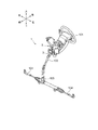
図1は本願の実施形態に係るステアリング装置2を用いたステアリング機構1を斜め前方から見た斜視図である。図1に示すように、本実施形態のステアリング装置2は、ステアリングコラムに回転可能に支持され、ステアリングホイール101からの操舵力を伝達するステアリングシャフト3および中間シャフト102からステアリングギヤ103に伝達された操舵力によって図示しないラック軸を左右に往復運動させることでラック軸に連結した左右のタイロッド104を介して前輪を転舵する。
FIG. 1 is a perspective view of a steering mechanism 1 using a steering device 2 according to an embodiment of the present application as viewed obliquely from the front. As shown in FIG. 1, the steering device 2 of the present embodiment is rotatably supported by a steering column, and is transmitted to a
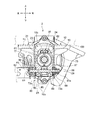
図2は、本願の実施形態に係るステアリング装置2の縦断面図である。図2に示すように、ステアリング装置2は、中間部を構成するアルミ合金ダイキャスト成形品で筒状のアウタコラム10と、車体100に取り付けられ、アウタコラム10の車両後方側部分を保持するチルトブラケット12と、アウタコラム10の車両後方側に内嵌したインナコラム11と、アウタコラム10の車両前方側に取り付けられた電動アシスト機構4と、インナコラム11および電動アシスト機構4によって中心軸線を中心とする回転を可能に支持されたステアリングシャフト3とを主要構成要素としている。
FIG. 2 is a longitudinal sectional view of the steering device 2 according to the embodiment of the present application. As shown in FIG. 2, the steering device 2 is an aluminum alloy die-cast molded product that constitutes an intermediate portion, and is attached to the tubular
(ステアリングコラム)
ステアリングコラムは、アウタコラム10とインナコラム11とから軸方向に伸縮可能に構成されている。アウタコラム10にはインナコラム11の外径よりも僅かに大きい内径を有する保持筒孔13が軸方向に沿って形成されており、この保持筒孔13にインナコラム11の車両前方側部分が内嵌している。
(Steering column)
The steering column is configured to extend and contract in the axial direction from the
インナコラム11のうち保持筒孔13と嵌合する部位の外周面には、低摩擦係数の樹脂コーティングが施されており、後述する二次衝突時にはインナコラム11が比較的小さな締付摩擦力に抗して車両前方側へ移動する。
A resin coating with a low friction coefficient is applied to the outer peripheral surface of a portion of the
図2に示すように、電動アシスト機構4のハウジング5の前側上部には、左右方向に貫通するボス孔22aに鋼管製のカラー21を保持したピボットボス22が形成されている。アウタコラム10は、径方向外方へ広がった前端部10fがボルト56によってハウジング5に固定されている。電動アシスト機構4、アウタコラム10、インナコラム11およびステアリングシャフト3は、ピボットボス22内を通した不図示のピボットボルトによって回動可能に車体100に取り付けられる。
As shown in FIG. 2, a
図3は本願の実施形態に係るステアリング装置2の図2に示すIII−III切断面を示す断面図である。図2、図3に示すように、アウタコラム10の上部には、上方に突出し、車両前後方向に延びる左右一対のガイド壁23、24を備えたガイド溝部25が形成されている。ガイド溝部25は、上側(径方向外側)が覆われた有底溝であり、アウタコラム10の径方向内側で車両後方端まで形成されている。アウタコラム10の下部には、図2に示すように、径方向に貫通し前後方向(軸方向)に延び、後方側が開放したスリット部26が設けられている。
FIG. 3 is a cross-sectional view showing the III-III cut surface shown in FIG. 2 of the steering device 2 according to the embodiment of the present application. As shown in FIGS. 2 and 3, a
図4は、図3に示す断面のアウタコラム10とその内側に収容された部材を拡大した拡大断面図である。アウタコラム10の車両後方側の下部には、下方に突出した一対のクランプ部10a、10aが形成されている。一対のクランプ部10a、10aには左右方向(車幅方向)に貫通した締付ボルト用の貫通孔28が穿孔されている。図3に示すように、この貫通孔28には、後述するチルト・テレスコピック調整機構80の締付ボルト81が通されている。後述するチルト・テレスコピック調整機構80によってインナコラム11を締付けるアウタコラム10の締付部10g(図4参照)は、クランプ部10aから更に車両後方側へ延びている。車両後方側へ延びた締付部10gの下端には、概略U字型をした変形抑制部10cが一体に形成されている(図2参照)。変形抑制部10cは、締付部10gの車両後方側部分の剛性を高めることで、締付部10gを後述するチルト・テレスコピック調整機構80によって締め付けた際に、締付部10gの車両後方側が車両前方側に比べて大きく変形し過ぎるのを防ぐ。
FIG. 4 is an enlarged cross-sectional view of the
インナコラム11の後端部内側には、図2に示すように、ステアリングシャフト3の車両後方側部分を構成するアッパーステアリングシャフト62を回転自在に支持するボールベアリング29が嵌装されている。
As shown in FIG. 2, a
(ストッパー)
図5は本願の実施形態に係るステアリング装置2の図2に示す縦断面図のうち可動側ストッパー30周辺を拡大して示す拡大断面図である。図5に示すように、インナコラム11の前方側の上部にはアウタコラム10のガイド溝部25内に収容された可動側ストッパー30が装着されている。アウタコラム10とインナコラム11との相対回転は、ガイド溝部25の内側側面と可動側ストッパー30との係合によって阻止される。
(stopper)
FIG. 5 is an enlarged cross-sectional view showing the periphery of the
ガイド溝部25の車両後方側部分には、断面がL字型をした固定側ストッパー33が取り付けられている。固定側ストッパー33は、ガイド溝部25の上面(アウタコラム10の外周面)に面接触してネジ止めされた板状の基部33aと、基部33aと一体に形成され、基部33aの車両前方側部分からガイド溝部25を径方向に貫通した孔(第3の孔)25cを通って下方へ延びる板状の遮断部33bとを有している。遮断部33bは、車両後方側にテレスコピック調整が行われた際に、可動側ストッパー30が当接することで、車両後方側のテレスコピック調整範囲(図2、図5において符号「TAr」にて示す。)を制限する。
A fixed-
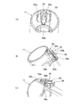
図6は本願の実施形態に係るステアリング装置2のインナコラム11と可動側ストッパー30を示す斜視図である。図6(a)は可動側ストッパー30を組み立てる前の状態を示し、(b)は可動側ストッパー30を組み立て、インナコラム11に取り付けた後の状態を示している。可動側ストッパー30は、金属材料から形成された芯金59と、芯金59に取り付けられた樹脂製の芯金押さえ60と、芯金59および芯金押さえ60に取り付けられた通電部材58とを有している。なお、図6(a)において芯金59と芯金押さえ60は別体に図示しているが、芯金押さえ60が芯金59と一体に成型されたものとしても良い。
FIG. 6 is a perspective view showing the
図7は本願の実施形態に係るステアリング装置2の可動側ストッパー30を示す斜視図である。(a)は車両右後方の下側から見た状態を示し、(b)は車両左後方の上側から見た状態を示し、(c)は車両左前方の下側から見た状態を示している。
FIG. 7 is a perspective view showing the
芯金59は、概略四角形の板状部59aと、板状部59aの中央から下方に突出した直方体状の凸部59bとを有している。
The
芯金押さえ60は、芯金59の板状部59aの外縁部を囲む囲繞部60aと、囲繞部60aの車両後方側中央部から下方(径方向内側)へ延びる係止爪60bとを有している。係止爪60bは、軸方向に対して垂直に配置された板状をしており、車両後方側面の下端から上下方向の中間部まで厚みを漸次厚くして傾斜面を形成し、その上部に概略水平な面を形成した突起を有している。
The cored
通電部材58は、芯金59および芯金押さえ60の上側を車幅方向に横切って芯金押さえ60の左右両側で下方へ延び、芯金押さえ60を挟み込み、中央が下方に屈曲して芯金59の板状部59aに接触した固定部58aと、固定部58aの両端部から車両前後方向にそれぞれ延びる摺接部58b、58c、58d、58eを有している。通電部材58は、金属などの導電性を有する材料から形成することができる。
The energizing
図6(a)に示すように、インナコラム11の車両前方側の上部には、径方向に貫通して形成された孔11b(第1の孔)と、孔11bの車両後方側に並んで配置された孔11c(第2の孔)とが形成されている。孔11bは、概略四角形状に形成されている。孔11cは、車幅方向に長い長方形状に形成されている。
As shown in FIG. 6 (a), a
可動側ストッパー30は、組み立てた後、芯金59の凸部59bを孔11bに差し込み、芯金押さえ60の係止爪60bを孔11cに差し込むことで、インナコラム11に容易に取り付けることができる。可動側ストッパー30は、インナコラム11をアウタコラム10に差し込む前に、インナコラム11に取り付ける。図5に示す固定側ストッパー33は、可動側ストッパー30が取り付けられたインナコラム11をアウタコラム10に差し込んだ後にアウタコラム10にネジ止めする。なお、固定側ストッパー33の代わりに、アウタコラム10の車両後方側部分に可動側ストッパー30に当接する部分を、アウタコラム10と一体に形成して固定側ストッパーとしてもよい。この場合、アウタコラム10のガイド溝部25を上下方向(径方向)に貫通した開口部を設け、インナコラム11をアウタコラム10に差し込んだ後にこの開口部から可動側ストッパー30を挿入してインナコラム11に取り付けるものとしても良い。
After the assembly, the
図8は、本願の実施形態に係るステアリング装置2のインナコラム11に取り付けた可動側ストッパー30を示す斜視図である。(a)は車両前方の下側から見た状態、(b)は車両左前方の下側から見た状態、(c)は車両左後方の上側から見た状態を示している。図9は、本願の実施形態に係るステアリング装置2の図4に示すIX−IX切断面を示す断面図である。
FIG. 8 is a perspective view showing the
図9に示すように、通電部材58の摺接部58b、58c、58d、58eは、芯金押さえ60とガイド壁23、24の間で弾性変形し、それぞれガイド溝部25の内壁25a、25bに所定の圧力で接触している。
As shown in FIG. 9, the sliding
自動車のステアリングホイール101にはホーンやエアバッグなどの電装部品が取り付けられ、これら電装部品の多くがボディアースであることから、ステアリングホイール101から車体100までの通電経路を確保する必要がある。ところが、上述のようにアウタコラム10の内周面又はインナコラム11の外周面に低摩擦材コーティングが施されると、当該コーティングによってインナコラム11とアウタコラム10との接触面を経由した通電経路による通電が困難となる。また、後述のようにステアリングシャフト3のスプライン嵌合部に樹脂コーティングが施されると、当該樹脂コーティングによってスプライン嵌合部を経由した通電経路による通電が困難となる。そこで、導電性を有する通電部材58がインナコラム11に接した芯金59とアウタコラム10のガイド溝部25に接することで、インナコラム11とアウタコラム10を電気的に接続し、ステアリングホイール101から車体100への通電経路を確保するものとしている。また、摺接部58b、58c、58d、58eが弾性変形してガイド溝部25の内壁25a、25bに所定の圧力で接触することで、アウタコラム10と可動側ストッパー30の間のガタ詰めを行っている。
Electrical components such as a horn and an airbag are attached to the
(チルトブラケット)
図3に示すように、チルトブラケット12は、左右方向に延びる上板71と、この上板71の下面に溶接された左右側板72、73とを有している。上板71は、ボルト等によって車体100に締結される。左右側板72、73の間隔は、自由状態でアウタコラム10の左右方向の幅よりも若干大きく設定されている。左右側板72、73には、チルト調整用長孔72a、73aが形成されている。チルト調整用長孔72a、73aは、前述したピボットボス22を中心とする円弧状に形成されている。
(Tilt bracket)
As shown in FIG. 3, the
図3に示すように、チルトブラケット12の下部には、ステアリングコラムのチルト調整およびテレスコピック調整に供されるチルト・テレスコピック調整機構80が設けられている。チルト・テレスコピック調整機構80は、アウタコラム10のクランプ部10a、10aに形成された締付ボルト用の貫通孔28に左方から挿入された締付ボルト81によって、使用者の操作に応じた締め付けとその解除を行い、これによりチルト・テレスコピック位置の固定とその解除を行う。
As shown in FIG. 3, a tilt /
図3に示すように、締付ボルト81には、その頭部とチルトブラケット12の左側板72との間に、運転者によって回転操作される操作レバー82と、操作レバー82と一体に回転する可動カム83と、右端がチルト調整用長孔72aに回転不能に係合した固定カム84とが外嵌している。固定カム84と可動カム83の対向する端面には、相補的な形状をした傾斜カム面が形成されている。固定カム84と可動カム83は、操作レバー82の回転に応じて、互いに噛み合って近接することで締付ボルト81による締め付けを解除し、互いに反発して遠ざかることで締付ボルト81に張力を発生させ、締め付けを行う。
As shown in FIG. 3, the tightening
図3に示すように、チルトブラケット12の左右側板72、73とアウタコラム10との間で、締付ボルト81には、後述するロアストッパ50から左右に延びる係止腕に先端が係合した左右各2枚の摩擦板85と、左右端板部86a、86bが左右両側でそれぞれ2枚の摩擦板85の間に挟まれた中間摩擦板86とが外嵌している。摩擦板85は、上述のようにロアストッパ50に係合しており、摩擦面を増やすことでアウタコラム10によるインナコラム11の保持を補強している。
As shown in FIG. 3, between the left and
図2に示すように、摩擦板85には、締付が解除された状態で締付ボルト81との相対移動を許し、テレスコピック調整を可能とすべく、前後方向に延びた長孔85aが設けられている。中間摩擦板86は、四角い板状の部材の中央に締付ボルト81が通る丸孔が形成され、摩擦板85に面接触する左右一対の端板部を連結板部によって連結した形状を呈している。
As shown in FIG. 2, the
図3に示すように、右側板73の外側では、押圧板87とスラスト軸受88とが締付ボルト81に外嵌しており、これらが締付ボルト81の雄ねじ81aにねじ込まれるナット89によって他の部材と共に締め付けられている。
As shown in FIG. 3, on the outside of the
(ロアストッパ)
図2に示すように、インナコラム11の前方側部分の下面には、スリット部26に遊嵌するアルミ合金ダイキャスト成型品のロアストッパ50が装着されている。ロアストッパ50の前端には軸方向かつ上下方向に切断した断面が略L字形状のバッファ保持部52が下方に向けて突出して形成されており、このバッファ保持部52にゴム製のバッファブロック53が保持されている。
(Lower stopper)
As shown in FIG. 2, a
バッファブロック53は、スリット部26の前端部に当接することにより、インナコラム11の前方へのテレスコピック調整範囲(図5中に符号「TAf」で示す)を制限する。
The
ロアストッパ50は、前後一対の樹脂ピン51によってインナコラム11に固定されている。2次衝突時において、バッファブロック53がスリット部26の前端部に衝突すると、樹脂ピン51が破断してロアストッパ50がインナコラム11から脱落する。これにより、インナコラム11の前方への更なる移動を許し、符号「CP」により示す範囲の移動が可能になることで、2次衝突の衝撃を緩和する。
The
(ステアリングシャフト)
図2に示すように、ステアリングシャフト3は、テレスコピック調整を可能とすべくステアリングコラム内で互いにスプライン結合されたロアステアリングシャフト61およびアッパーステアリングシャフト62と、トーションバー44を介してロアステアリングシャフト61と連結された出力軸39とによって構成されている。ステアリングシャフト3は、インナコラム11の後方側部分に嵌挿されたボールベアリング29と、電動アシスト機構4のハウジング5に嵌挿されたボールベアリング37、38とによって回転自在に支持されている。
(Steering shaft)
As shown in FIG. 2, the steering
ロアステアリングシャフト61は、鋼丸棒を素材として転造やブローチ加工などによって成型可能であり、後半部の外周に雄スプライン61aを有している。一方、アッパーステアリングシャフト62は、鋼管を素材として絞り加工やブローチ加工などによって成型可能であり、前半部の内周にロアステアリングシャフト61の雄スプライン61aに嵌合する雌スプライン62aを有している。
The
ロアステアリングシャフト61の雄スプライン61aには、アッパーステアリングシャフト62の雌スプライン62aとのがた付きを防止すべく、樹脂コーティングが施されている。なお、樹脂コーティングに代えて低摩擦材のコーティングとすることもできる。
A resin coating is applied to the
アッパーステアリングシャフト62の後端にはステアリングホイール101のボス101a(図2にて破線で示す)が外嵌するセレーション62bが形成されている。
A
<実施形態の作用>
図3に示すように、運転者が操作レバー82を締め付け側に回動させると、固定カム84の傾斜カム面の山に可動カム83の傾斜カム面の山が乗り上げ、締付ボルト81を左側に引っ張る一方で固定カム84を右側に押圧する。これにより、左右側板72、73がアウタコラム10のクランプ部10a、10aを左右から締め付け、ステアリングコラムのチルト方向の移動を制限するのと同時に、アウタコラム10がインナコラム11を締め付ける締付摩擦力と摩擦板85に生じる摩擦力とによってインナコラム11の軸方向の移動が制限される。
<Operation of Embodiment>
As shown in FIG. 3, when the driver rotates the
一方、運転者が操作レバー82を解除方向に回動させると、上述のように自由状態における間隔がアウタコラム10の幅より広いチルトブラケット12の左右側板72、73がそれぞれ弾性復帰する。これにより、アウタコラム10のチルト方向の移動の制限とインナコラム11の軸方向の移動の制限がともに解除され、使用者がステアリングホイール101の位置の調整を行うことができるようになる。
On the other hand, when the driver rotates the
この状態において、使用者は、図2、図5に符号「TAr」で示すように、可動側ストッパー30と固定側ストッパー33の間の軸方向距離だけステアリングホイール101を車両後方側へ移動させることができる。車両後方側へのテレスコピック調整によって可動側ストッパー30が所定の位置(「TAr」だけ後方へ移動した位置)に達すると、固定側ストッパー33の遮断部33bに可動側ストッパー30が当接する。固定側ストッパー33に当接する際に可動側ストッパー30が受ける荷重は、芯金55からインナコラム11に伝えられる。
In this state, the user moves the
図5、図6に示すように、芯金押さえ60の係止爪60bが挿入される孔(第2の孔)11cは、芯金59の凸部59bが挿入される孔(第1の孔)11bに対して、可動側ストッパー30が固定側ストッパー33に当接する側に配置されている。したがって、孔11bと孔11cの間のインナコラム11の部分(横断部11d)は、可動側ストッパー30が固定側ストッパー33に当接した際、芯金59からの荷重を受けない。仮に、孔11bと孔11cを入れ替えて配置した場合、芯金59からインナコラム11へ伝わる荷重が孔11bと孔11cの間の横断部11dにかかり、横断部11dが破損しやすくなる。このことは、孔11bと孔11cを円周方向に並べて配置した場合にも同様のことが言える。この場合、インナコラム11が中心軸線を中心としていずれかの方向に回転し、可動側ストッパー30がアウタコラム10のガイド溝部25に押し当てられた場合に、孔11bと孔11cとの間のインナコラム11の部分は、可動側ストッパー30がアウタコラム10からの荷重を受けることになるため、好ましくない。
As shown in FIGS. 5 and 6, the hole (second hole) 11 c into which the locking
以上に説明した実施形態によれば、組み立てが容易であり、製造コストの増加を抑えることができるステアリング装置を提供することができる。 According to the embodiment described above, it is possible to provide a steering device that is easy to assemble and can suppress an increase in manufacturing cost.
上記実施形態の説明においては、本発明の理解を助けるために具体的な説明を行ったが、本発明はこれらに限られるものではなく、変更、改良などが可能である。 In the description of the above embodiment, specific explanations have been given in order to help understanding of the present invention, but the present invention is not limited to these, and modifications, improvements, and the like are possible.
例えば、上記実施形態はコラムアシスト型電動パワーステアリング装置に本発明を適用したものであるが、ラックアシスト型電動パワーステアリング装置などの他のステアリング装置にも当然に適用可能である。また、固定側ストッパーをアウタコラムの車輌前方側部分に設け、第2の穴を第1の穴の車両前方側に配置し、可動側ストッパーの係止爪を芯金の車両前方側に配置することで、車両前方側へのテレスコピック調整の範囲を制限するものとしても良い。 For example, although the above embodiment is an application of the present invention to a column assist type electric power steering device, it is naturally applicable to other steering devices such as a rack assist type electric power steering device. In addition, a fixed stopper is provided on the vehicle front side portion of the outer column, the second hole is disposed on the vehicle front side of the first hole, and the locking claw of the movable stopper is disposed on the vehicle front side of the core metal. Thus, the range of telescopic adjustment to the front side of the vehicle may be limited.
また、ステアリングコラムやチルト・テレスコピック調整機構80、可動側ストッパー30などの具体的構成や形状についても、本発明の趣旨を逸脱しない範囲で適宜変更可能である。
In addition, specific configurations and shapes of the steering column, the tilt /
例えば、係止爪60bは、上記実施形態のものに限らず、インナコラム11に形成された孔11cに挿入して、可動側ストッパー30がインナコラム11から外れるのを防ぐものであれば、どのような形状であってもよい。また、通電部材58は、インナコラム11とアウタコラム10とを電気的に接続するものであれば良く、例えば、インナコラム11に直接接していても良い。なお、可動側ストッパー30は、通電部材58を有さなくても良い。
For example, the latching
また、固定側ストッパー33の形状や取付方法も上記実施形態のものに限らず、インナコラム11をアウタコラム10に差し込んだ後にガイド溝部25内に可動側ストッパー30と当接する部分を構成するものであればよい。
Further, the shape and mounting method of the fixed-
また、インナコラム11の第1の孔11bと第2の孔11cの間に横断部11dを設けず、第1の孔11bと第2の孔11cを軸方向に連続した1つの孔として形成もよい。例えば、第1の孔11bの軸方向前端から第2の孔11cの軸方向後端に至る長孔としてもよい。
Further, the crossing
1 ステアリング機構
2 ステアリング装置
3 ステアリングシャフト
4 電動アシスト機構
5 ハウジング
10 アウタコラム
10a クランプ部
10c 変形抑制部
10f 前端部
10g 締付部
11 インナコラム
11b、11c 孔
11d 横断部
12 チルトブラケット
13 保持筒孔
21 カラー
22 ピボットボス
22a ボス孔
23、24 ガイド壁
25 ガイド溝部
25a、25b 内壁
25c 孔
26 スリット部
28 貫通孔
29 ボールベアリング
30 可動側ストッパー
33 固定側ストッパー
33a 基部
33b 遮断部
37、38 ボールベアリング
39 出力軸
44 トーションバー
50 ロアストッパ
51 樹脂ピン
52 バッファ保持部
53 バッファブロック
56 ボルト
58 通電部材
58a 固定部
58b、58c、58d、58e 摺接部
59 芯金
59a 板状部
59b 凸部
60 芯金押さえ
60a 囲繞部
60b 係止爪
61 ロアステアリングシャフト
61a 雄スプライン
62 アッパーステアリングシャフト
62a 雌スプライン
62b セレーション
71 上板
72 左側板
72a チルト調整用長孔
73 右側板
73a チルト調整用長孔
80 チルト・テレスコピック調整機構
81 締付ボルト
81a 雄ねじ
82 操作レバー
83 可動カム
84 固定カム
85 摩擦板
85a 長孔
86 中間摩擦板
87 押圧板
88 スラスト軸受
89 ナット
100 車体
101 ステアリングホイール
101a ボス部
102 中間シャフト
103 ステアリングギヤ
104 タイロッド
DESCRIPTION OF SYMBOLS 1 Steering mechanism 2 Steering device 3 Steering shaft 4 Electric assist mechanism 5 Housing 10 Outer column 10a Clamp part 10c Deformation suppression part 10f Front end part 10g Tightening part 11 Inner column 11b, 11c hole 11d Crossing part 12 Tilt bracket 13 Holding cylinder hole 21 Collar 22 Pivot Boss 22a Boss Hole 23, 24 Guide Wall 25 Guide Groove 25a, 25b Inner Wall 25c Hole 26 Slit 28 Through Hole 29 Ball Bearing 30 Movable Stopper 33 Fixed Side Stopper 33a Base 33b Blocking Section 37, 38 Ball Bearing 39 Output Shaft 44 Torsion bar 50 Lower stopper 51 Resin pin 52 Buffer holding part 53 Buffer block 56 Bolt 58 Current supply member 58a Fixing part 58b, 58c, 58d 58e Sliding contact part 59 Core metal 59a Plate-like part 59b Convex part 60 Core metal presser 60a Surrounding part 60b Locking claw 61 Lower steering shaft 61a Male spline 62 Upper steering shaft 62a Female spline 62b Serration 71 Upper plate 72 Left side plate 72a Tilt adjustment Long hole 73 Right side plate 73a Tilt adjustment long hole 80 Tilt / telescopic adjustment mechanism 81 Tightening bolt 81a Male screw 82 Operation lever 83 Movable cam 84 Fixed cam 85 Friction plate 85a Long hole 86 Intermediate friction plate 87 Press plate 88 Thrust bearing 89 Nut 100 Car body 101 Steering wheel 101a Boss part 102 Intermediate shaft 103 Steering gear 104 Tie rod
Claims (7)
軸方向に延びるガイド溝部を備え、前記ステアリングシャフトを回転可能に支持するアウタコラムと、
軸方向の相対移動を可能に、車両前方側部分が前記アウタコラムに内嵌し、前記アウタコラムと共に前記ステアリングシャフトを回転可能に支持するインナコラムと、
前記ガイド溝部内に収容され、前記インナコラムに取り付けられ、テレスコピック調整の際に所定の位置で固定側ストッパーに当接することでテレスコピック調整範囲を制限する可動側ストッパーと、を有し、
前記インナコラムには、径方向に貫通した第1の孔と、前記第1の孔と軸方向に並んで配置され、径方向に貫通した第2の孔とが形成されており、
前記第2の孔は、前記第1の孔に対して、前記固定側ストッパーの側に形成されており、
前記可動側ストッパーは、前記第1の孔に挿入され、前記固定側ストッパーに当接する際の荷重を前記インナコラムに伝える芯金と、前記芯金に固定され、前記芯金が前記インナコラムから外れるのを防ぐ芯金押さえとを有し、
前記芯金押さえは、径方向内側に延び、前記第2の孔に挿入された係止爪を有することを特徴とするステアリング装置。 A steering shaft that transmits steering force;
An outer column having a guide groove extending in the axial direction and rotatably supporting the steering shaft;
An inner column in which a front portion of the vehicle is fitted into the outer column so as to allow relative movement in the axial direction, and the steering shaft is rotatably supported together with the outer column;
A movable-side stopper that is accommodated in the guide groove portion, is attached to the inner column, and restricts a telescopic adjustment range by contacting the fixed-side stopper at a predetermined position during telescopic adjustment;
The inner column is formed with a first hole penetrating in the radial direction, and a second hole penetrating in the radial direction, arranged side by side with the first hole,
The second hole is formed on the fixed stopper side with respect to the first hole,
The movable-side stopper is inserted into the first hole and transmits a load when contacting the fixed-side stopper to the inner column, and is fixed to the cored bar, and the cored bar is removed from the inner column. It has a mandrel presser that prevents it from coming off,
The metal core presser has a locking claw extending inward in the radial direction and inserted into the second hole.
前記固定側ストッパーは、前記ガイド溝部に径方向に貫通して形成された第3の孔を通して前記アウタコラムの径方向外側から径方向内側に挿入された遮断部と、前記遮断部と一体に形成され、前記アウタコラムの外周面に固定された基部とを有することを特徴とする請求項1または2に記載のステアリング装置。 The guide groove is a bottomed groove formed to the vehicle rear end on the radially inner side of the outer column,
The fixed-side stopper is formed integrally with a blocking portion inserted from the radially outer side to the radially inner side of the outer column through a third hole formed through the guide groove portion in the radial direction. The steering apparatus according to claim 1, further comprising a base fixed to an outer peripheral surface of the outer column.
Priority Applications (1)
| Application Number | Priority Date | Filing Date | Title |
|---|---|---|---|
| JP2016122139A JP6759746B2 (en) | 2016-06-20 | 2016-06-20 | Steering device |
Applications Claiming Priority (1)
| Application Number | Priority Date | Filing Date | Title |
|---|---|---|---|
| JP2016122139A JP6759746B2 (en) | 2016-06-20 | 2016-06-20 | Steering device |
Publications (2)
| Publication Number | Publication Date |
|---|---|
| JP2017226257A true JP2017226257A (en) | 2017-12-28 |
| JP6759746B2 JP6759746B2 (en) | 2020-09-23 |
Family
ID=60890771
Family Applications (1)
| Application Number | Title | Priority Date | Filing Date |
|---|---|---|---|
| JP2016122139A Active JP6759746B2 (en) | 2016-06-20 | 2016-06-20 | Steering device |
Country Status (1)
| Country | Link |
|---|---|
| JP (1) | JP6759746B2 (en) |
Cited By (1)
| Publication number | Priority date | Publication date | Assignee | Title |
|---|---|---|---|---|
| JP7363646B2 (en) | 2019-04-25 | 2023-10-18 | 株式会社ジェイテクト | steering device |
Citations (6)
| Publication number | Priority date | Publication date | Assignee | Title |
|---|---|---|---|---|
| JPS62192955U (en) * | 1986-05-30 | 1987-12-08 | ||
| JPS63117757U (en) * | 1987-01-27 | 1988-07-29 | ||
| WO2005023622A1 (en) * | 2003-09-03 | 2005-03-17 | Nsk Ltd. | Impact absorbing steering column device with telescopic mechanism |
| GB2510822A (en) * | 2013-02-13 | 2014-08-20 | Nsk Deutschland Gmbh | Steering column |
| WO2015190301A1 (en) * | 2014-06-13 | 2015-12-17 | 日本精工株式会社 | Steering device |
| WO2016076266A1 (en) * | 2014-11-10 | 2016-05-19 | 日本精工株式会社 | Shock absorbing steering device |
-
2016
- 2016-06-20 JP JP2016122139A patent/JP6759746B2/en active Active
Patent Citations (6)
| Publication number | Priority date | Publication date | Assignee | Title |
|---|---|---|---|---|
| JPS62192955U (en) * | 1986-05-30 | 1987-12-08 | ||
| JPS63117757U (en) * | 1987-01-27 | 1988-07-29 | ||
| WO2005023622A1 (en) * | 2003-09-03 | 2005-03-17 | Nsk Ltd. | Impact absorbing steering column device with telescopic mechanism |
| GB2510822A (en) * | 2013-02-13 | 2014-08-20 | Nsk Deutschland Gmbh | Steering column |
| WO2015190301A1 (en) * | 2014-06-13 | 2015-12-17 | 日本精工株式会社 | Steering device |
| WO2016076266A1 (en) * | 2014-11-10 | 2016-05-19 | 日本精工株式会社 | Shock absorbing steering device |
Cited By (1)
| Publication number | Priority date | Publication date | Assignee | Title |
|---|---|---|---|---|
| JP7363646B2 (en) | 2019-04-25 | 2023-10-18 | 株式会社ジェイテクト | steering device |
Also Published As
| Publication number | Publication date |
|---|---|
| JP6759746B2 (en) | 2020-09-23 |
Similar Documents
| Publication | Publication Date | Title |
|---|---|---|
| JP6350639B2 (en) | Steering device | |
| JP5999288B2 (en) | Steering device | |
| JP5428582B2 (en) | Steering device | |
| JP6028872B2 (en) | Steering device | |
| JP6620880B2 (en) | Steering device | |
| EP3118084B1 (en) | Steering device | |
| US20100139439A1 (en) | Steering column system | |
| JP2005075250A (en) | Shock absorbing type steering column device with telescopic mechanism | |
| JP2008168892A (en) | Steering device | |
| JP6390295B2 (en) | Steering device | |
| WO2018181304A1 (en) | Steering device | |
| JP6562103B2 (en) | Steering device | |
| JP2017226257A (en) | Steering device | |
| WO2013187124A1 (en) | Steering lock device | |
| JP6819241B2 (en) | Steering device | |
| JP2019142500A (en) | Steering apparatus | |
| JP2019116274A (en) | Steering device | |
| JP2019089557A (en) | Steering device | |
| JP6699781B2 (en) | Steering device | |
| JP6349891B2 (en) | Steering device | |
| JP6733774B2 (en) | Steering device | |
| WO2019016947A1 (en) | Steering device | |
| JP2019116275A (en) | Steering device | |
| JP2019116273A (en) | Steering device | |
| JP2019116272A (en) | Steering device |
Legal Events
| Date | Code | Title | Description |
|---|---|---|---|
| A621 | Written request for application examination |
Free format text: JAPANESE INTERMEDIATE CODE: A621 Effective date: 20190516 |
|
| RD02 | Notification of acceptance of power of attorney |
Free format text: JAPANESE INTERMEDIATE CODE: A7422 Effective date: 20190516 |
|
| A977 | Report on retrieval |
Free format text: JAPANESE INTERMEDIATE CODE: A971007 Effective date: 20200227 |
|
| A131 | Notification of reasons for refusal |
Free format text: JAPANESE INTERMEDIATE CODE: A131 Effective date: 20200317 |
|
| A521 | Request for written amendment filed |
Free format text: JAPANESE INTERMEDIATE CODE: A523 Effective date: 20200518 |
|
| TRDD | Decision of grant or rejection written | ||
| A01 | Written decision to grant a patent or to grant a registration (utility model) |
Free format text: JAPANESE INTERMEDIATE CODE: A01 Effective date: 20200804 |
|
| A61 | First payment of annual fees (during grant procedure) |
Free format text: JAPANESE INTERMEDIATE CODE: A61 Effective date: 20200817 |
|
| R150 | Certificate of patent or registration of utility model |
Ref document number: 6759746 Country of ref document: JP Free format text: JAPANESE INTERMEDIATE CODE: R150 |