JP2017223916A - Printer - Google Patents
Printer Download PDFInfo
- Publication number
- JP2017223916A JP2017223916A JP2016121133A JP2016121133A JP2017223916A JP 2017223916 A JP2017223916 A JP 2017223916A JP 2016121133 A JP2016121133 A JP 2016121133A JP 2016121133 A JP2016121133 A JP 2016121133A JP 2017223916 A JP2017223916 A JP 2017223916A
- Authority
- JP
- Japan
- Prior art keywords
- discharge tray
- discharge
- airflow
- printing apparatus
- port
- Prior art date
- Legal status (The legal status is an assumption and is not a legal conclusion. Google has not performed a legal analysis and makes no representation as to the accuracy of the status listed.)
- Pending
Links
Images


Landscapes
- Accessory Devices And Overall Control Thereof (AREA)
- Paper Feeding For Electrophotography (AREA)
- Electrophotography Configuration And Component (AREA)
- Control Or Security For Electrophotography (AREA)
- Pile Receivers (AREA)
- Facsimiles In General (AREA)
Abstract
Description
本発明は印刷装置に関する。 The present invention relates to a printing apparatus.
画像形成装置などの印刷装置にあっては、特にゴミや粉塵などの塵埃の多い環境下で使用される場合でも、装置内部に塵埃が侵入しないようにする必要がある。 In a printing apparatus such as an image forming apparatus, it is necessary to prevent dust from entering the inside of the apparatus even when used in an environment with a lot of dust, such as dust or dust.
従来、例えば、操作、点検、消耗品交換などのときに使用する開口部を開閉可能に覆う開閉手段を有する防塵カバーを備えたものがある(特許文献1)。また、装置の配線を通す開口部の外側に内部への外気流入を遮断する空気流を形成する空気供給装置を備えるものがある(特許文献2)。 2. Description of the Related Art Conventionally, for example, there is one provided with a dustproof cover having an opening / closing means that covers an opening used for operation, inspection, replacement of consumables and the like so as to be opened and closed (Patent Document 1). In addition, there is an apparatus provided with an air supply device that forms an air flow that blocks an outside air inflow outside the opening through which the wiring of the device passes (Patent Document 2).
ところで、印刷装置においては、媒体を排出トレイ上に排出する排出口が必要であり、この排出口から粉塵が内部に侵入することを防止しなければならないという課題がある。 By the way, in a printing apparatus, the discharge port which discharges | emits a medium on a discharge tray is required, and there exists a subject that it must prevent that a dust penetrate | invades from this discharge port.
本発明は上記の課題に鑑みてなされたものであり、排出口からの粉塵の侵入を抑制することを目的とする。 This invention is made | formed in view of said subject, and it aims at suppressing the penetration | invasion of the dust from a discharge port.
上記の課題を解決するため、本発明に係る印刷装置は、
画像が印刷された媒体が排出される排出トレイと、
前記排紙トレイの上方に配置され、前記媒体の排出口よりも排出方向と直交する方向の幅が広い吹き出し口と、
前記吹き出し口から前記排出トレイに向けて吹き出す気流を発生させる気流発生手段と、を備えている
構成とした。
In order to solve the above problems, a printing apparatus according to the present invention includes:
A discharge tray for discharging the medium on which the image is printed;
A blow-out port disposed above the discharge tray and having a wider width in a direction perpendicular to the discharge direction than the discharge port of the medium;
An airflow generating means for generating an airflow that blows out from the outlet toward the discharge tray.
本発明によれば、排出口からの粉塵の侵入を抑制することができる。 According to the present invention, intrusion of dust from the discharge port can be suppressed.
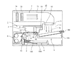
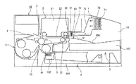
以下、本発明の実施の形態について添付図面を参照して説明する。本発明の第1実施形態について図1ないし図5を参照して説明する。図1は同実施形態に係る印刷装置の斜視説明図、図2は同じく機構部の側面説明図、図3は同じく正面説明図、図4は同じく気流経路の説明に供する正面説明図、図5は同じく排出トレイに用紙が積載された状態での正面説明図である。 Embodiments of the present invention will be described below with reference to the accompanying drawings. A first embodiment of the present invention will be described with reference to FIGS. 1 is a perspective explanatory view of the printing apparatus according to the embodiment, FIG. 2 is also a side explanatory view of the mechanism, FIG. 3 is also a front explanatory view, and FIG. 4 is a front explanatory view for explaining the air flow path. FIG. 4 is a front explanatory view in a state where sheets are stacked on the discharge tray.
この印刷装置は、装置本体10内に、印刷機構部1として、媒体である用紙100に画像を印刷する印刷部2と、用紙100を搬送する搬送部3とを備えている。また、搬送部3に給送する用紙100を収容する給紙カセット104を含む給紙部4と、画像が印刷された用紙100が排出される排出トレイ105を含む排出部5とを備えている。また、一面に印刷が施された用紙100を反転する反転部6を備えている。
This printing apparatus includes, in the apparatus
また、装置本体10の前面(正面)側には、排出トレイ105上の用紙100を取出す開口部11が設けられている。また、装置本体10の前面上側には操作パネル19が設けられている。
An
そして、印刷機構部1は、給紙部4の給紙カセット104の用紙100を給紙コロ41で一枚ずつ分離して送り出し、搬送部3に給送する。
Then, the
搬送部3は、駆動ローラ32及び従動ローラ33に掛け回されて周回移動する搬送ベルト31に給送された用紙100を吸着して印刷部2に対向して搬送する。一方、印刷部2は、例えば紙面垂直方向に往復移動するキャリッジ21に搭載された液体吐出ヘッド22から用紙100に向けてインクを吐出する。これにより、用紙100に所要の画像が印刷される。
The
その後、画像が印刷された用紙100は、一方を拍車コロとする排紙ローラ対52によって排出口51から排出トレイ105上に排出されて積載される。排出トレイ105上に排出された用紙100は、装置本体10の筐体開口部11から取出すことができる。
Thereafter, the
なお、両面印刷を行うときには、一面への印刷が完了した用紙100を、搬送ベルト31を逆転して反転部6に送り込んで表裏反転して再度搬送部3に給送して、他面への印刷を行って排出する。
When performing double-sided printing, the
ここで、装置本体10の内部には上下左右が囲まれ、開口部11で開口する胴内空間12を設け、胴内空間12の奥部に排出口51を配置し、胴内空間12に排出トレイ105を配置している。これにより、排出トレイ105が装置本体10の外側面からはみ出す量を少なくしている。
Here, the inside of the apparatus
そして、装置本体10内の上部部分に気流発生機構部7を配置している。
And the airflow
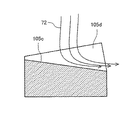
気流発生機構部7は、胴内空間12において、排出トレイ105の上方に配置され、排出トレイ105に向かって開口する吹き出し口71と、吹き出し口71から排出トレイ105に向けて吹出す気流72を発生させる気流発生手段としてファン73とを備えている。なお、ファン73の外気を取り入れ側にはフィルタ74が配置され、ファン73から吹き出し口71まではダクト75で経路が形成されている。
The airflow
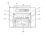
ここで、図3に示すように、吹き出し口71の排出方向と直交する方向の幅L2は、排出口51の幅L1よりも広くしている。
Here, as shown in FIG. 3, the width L <b> 2 in the direction orthogonal to the discharge direction of the
このように構成したので、気流発生機構部7の吹き出し口71から排出トレイ105に向けて気流72を吹出すことによって、排出口51の外側に、排出口51よりも幅の広い範囲にわたって気流72のカーテン(エアーカーテン)を形成することができる。
Since it comprised in this way, the
これにより、排出口51から粉塵が装置本体10の内部に侵入することを防止できる。
Thereby, dust can be prevented from entering the inside of the apparatus
また、胴内空間12内では、排出トレイ105の排出方向と直交する方向の両側端部の側方に、気流発生機構部7の吹き出し口71から排出トレイ105に向けて吹出された気流72を装置本体10の外方に逃す逃がし路171を設けている。
Further, in the in-
すなわち、上述したように、吹き出し口71は装置本体10の胴内空間12に配置することで、排出口51の排出方向下流側に効率的にエアーカーテンを形成することができる。
That is, as described above, the
このとき、装置本体10の開口部11以外に吹き出し口71から吹き出される気流72の逃げ場がないと、排出トレイ105に当たった気流72が乱れてエアーカーテンができなくなるおそれがある。
At this time, if there is no escape place for the
そこで、胴内空間12において、排出トレイ105の側方に気流72を逃す逃がし路171を配置することで、吹き出し口71から排出トレイ105に当たった気流72が排出トレイ105の側方の逃がし路171から逃げることができる。これにより、気流72の流れが安定し、エアーカーテンを安定して形成することができる。
Therefore, in the in-
なお、ここでは、逃がし路171は、装置本体10の外方に開口している例で示しているが、装置本体10内の空冷用にフィルタなどで粉塵を除去した後に、装置内を循環させる構成とすることもできる。
Here, although the
また、排出トレイ105は、図3及び図4に示すように、排出方向と直交する方向において、中央部から両側端部に向かって下がる方向に湾曲して傾斜する傾斜面(湾曲面)105a、105aを有する形状である。この場合、傾斜面105aは直線的に傾斜する傾斜形状であってもよい。
Further, as shown in FIGS. 3 and 4, the
このように、排出トレイ105は中央部が凸で左右に気流72を誘導する形状とすることで、排出トレイ105の上方からの気流72が左右に分岐し、左右に設けられた逃がし路171へ案内される。これにより、より安定した空気の流れが生じ、排出口51の開口下流側に安定してエアーカーテンを形成することができる。
In this way, the
この場合、図5に示すように、用紙100が排出トレイ105上にスタック(積載)された状態であっても、排出トレイ105の中央部が凸部となっていることで、用紙100が傾斜面105aに沿って撓む。
In this case, as shown in FIG. 5, even when the
この用紙100の撓みに沿って気流72が逃がし路171に誘導されるので、用紙100が排出トレイ105上にスタックされていても、エアーカーテンの形成に影響はない。
Since the
次に、本発明の第2実施形態について図6を参照して説明する。図6は同実施形態に係る印刷装置の正面説明図である。 Next, a second embodiment of the present invention will be described with reference to FIG. FIG. 6 is an explanatory front view of the printing apparatus according to the embodiment.
本実施形態では、逃がし路171内に、吸引手段である吸引ファン172を配置し、強制的に気流72を逃がし路171内に吸引している。
In the present embodiment, a
これにより、排出口51の幅が広く吹き出し口71の幅が広くなる場合でも、安定した気流の流れを生成してエアーカーテンの形成をより確実に行うことができる。
Thereby, even when the width of the
この場合、吸引ファン172の上流側に粉塵を除去するフィルタ173を設けることが好ましい。
In this case, it is preferable to provide a
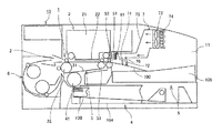
次に、本発明の第3実施形態について図7を参照して説明する。図7は同実施形態に係る印刷装置の機構部の側面説明図である。 Next, a third embodiment of the present invention will be described with reference to FIG. FIG. 7 is an explanatory side view of the mechanism unit of the printing apparatus according to the embodiment.
本実施形態では、吹き出し口71を、排紙方向斜め下流側に向けて気流72を吹き出す構成としている。
In the present embodiment, the
これにより、外気が排出口51により入りにくくなる。
Thereby, it becomes difficult for outside air to enter through the
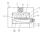
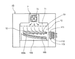
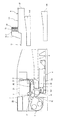
次に、本発明の第4実施形態について図8及び図9を参照して説明する。図8は同実施形態に係る印刷装置の正面説明図、図9は同じく排出トレイに用紙が積載された状態での正面説明図である。 Next, a fourth embodiment of the present invention will be described with reference to FIGS. FIG. 8 is a front explanatory view of the printing apparatus according to the embodiment, and FIG. 9 is a front explanatory view in a state where sheets are similarly stacked on the discharge tray.
本実施形態では、排出トレイ105は、排出方向と直交する方向において、一方側から他方側に向かって下がる方向に湾曲して傾斜する傾斜面(湾曲面)105bを有する形状である。この場合、傾斜面105bは直線的に傾斜する傾斜形状であってもよい。
In the present embodiment, the
そして、傾斜面105bを下った先に逃がし路171を配置している。逃がし路171内には、吸引ファン172、フィルタ173が配置されている。
And the
このように構成したので、排出トレイ105の上方からの気流72が排出トレイ105の傾斜面105bが低くなった側の側方の逃がし路171へ案内される。これにより、より安定した空気の流れが生じ、排出口51の開口下流側に安定してエアーカーテンを形成することができる。
Since it comprised in this way, the
この場合、排出トレイ105上に用紙100が積載されても、用紙100が傾斜面105bに倣うので、気流72を逃がし路171に誘導することができ、エアーカーテンの形成に影響はない。
In this case, even when the
これにより、逃がし路171及び吸引ファン172を1つにすることができ、装置構成の自由度が増える。
Thereby, the
次に、本発明の第5実施形態について図10を参照して説明する。図10は同実施形態に係る印刷装置の機構部の側面説明図である。 Next, a fifth embodiment of the present invention will be described with reference to FIG. FIG. 10 is an explanatory side view of the mechanism unit of the printing apparatus according to the embodiment.
装置本体10の胴内空間12で気流72を排出トレイ105に上方から排出トレイ105に向けて吹き出し、装置本体10の開口部11から排出トレイ105の一部が突き出す構成としている。
In the
これにより、用紙100を取り出そうとする使用者の手Hがエアーカーテンの内部に入ることがなくなり、使用者が用紙100を取り出しやすくなると共に、用紙100を取り出すときに、気流72を乱してエアーカーテンを維持できない状態や、使用者に付着した塵埃がエアーカーテンの内部に直接入ることを避けることができる。
This prevents the user's hand H who is trying to take out the
次に、本発明の第6実施形態について図11ないし図14を参照して説明する。図11は同実施形態に係る印刷装置の正面説明図、図12は同じく排出トレイ上での気流の流れの説明に供する斜視説明図、図13は同じく排出トレイ上での気流の流れの説明に供する断面説明図である。図15は同じく排出トレイ上に用紙が積載された状態での正面説明図である。 Next, a sixth embodiment of the present invention will be described with reference to FIGS. 11 is a front explanatory view of the printing apparatus according to the embodiment, FIG. 12 is a perspective explanatory view for explaining the flow of airflow on the discharge tray, and FIG. 13 is also for explaining the flow of airflow on the discharge tray. It is sectional explanatory drawing to provide. FIG. 15 is an explanatory front view showing a state in which sheets are similarly stacked on the discharge tray.
排出トレイ105には、排出方向と直交する方向において、両側に向かう傾斜面105a、105aとともに、中央部に排出方向に沿って下方向に向かう傾斜面105cを有する凹部105dが設けられている。この場合、傾斜面105cは、気流72を装置本体10の開口部11側に向かって誘導する傾斜形状となる。
The
これにより、排出トレイ105に排出された用紙100を支える接点が増えて、用紙100をより安定的にストックすることができる。
As a result, the number of contacts that support the
この場合、凹部105dを設けると、気流72のすべてを左右の逃がし路171に誘導できなくなってしまうため、凹部105dは、排出トレイ105上方からの気流72を装置本体10の開口部11に誘導するための傾斜面105cとし、気流72を開口部11に案内して逃がしている。
In this case, if the
これにより、凹部105dがあっても、装置本体10の内部に侵入する方向の気流は生じることがなくなり、装置本体100内部への塵埃の侵入を防ぐことができる。
Thereby, even if there exists the recessed
この場合、図14に示すように、排出トレイ105上に用紙100が排出されると、気流72は両側の逃がし路171に誘導されるので、気流72は排出トレイ105の中央部の凹部105dの形状の影響は受けなくなる。
In this case, as shown in FIG. 14, when the
次に、本発明の第7実施形態について図15を参照して説明する。図15は同実施形態に係る印刷装置の正面模式説明図である。 Next, a seventh embodiment of the present invention will be described with reference to FIG. FIG. 15 is a schematic front view of the printing apparatus according to the embodiment.
本実施形態では、装置本体10内に、気流発生機構部7と逃がし路171とをつなぐ循環路174を設けている。
In the present embodiment, a
これにより、逃がし路171から気流72を吸引する吸引ファンを別途設けることなく、気流発生機構部7のファン73で吸引を行うことができ、ファンの数を少なくすることができる。
Thereby, it is possible to perform the suction with the
また、循環路174内でフィルタ173を通過した空気を循環させることで、外気を取り込む量が減り、外気からの塵埃の侵入を抑制することができ、フィルタ173の寿命を延ばすこともできる。
Further, by circulating the air that has passed through the
なお、エアーカーテンの流量やフィルタを通した空気を送ることを優先させて、循環路174内にも吸引ファンを別途配置する構成とすることもできる。
Note that a suction fan may be separately arranged in the
次に、本発明の第8実施形態について図16を参照して説明する。図16は同実施形態に係る印刷装置の正面模式説明図である。 Next, an eighth embodiment of the present invention will be described with reference to FIG. FIG. 16 is a schematic front view of the printing apparatus according to the embodiment.
排出トレイ105は、装置本体10の胴内空間12内にすべて収容されている。そして、装置本体10には、胴内空間12の開口である開口部11を開閉する第1カバー部材である蓋部材14を開閉可能に設けている。
The
これにより、装置の電源が切断されてエアーカーテンを形成できない場合にも、図16(b)に示すように、蓋部材14を閉じることで、内部への塵埃の侵入を防ぐことができる。そして、装置の電源を入れて起動し、排出トレイ105に用紙100を排出するときには、図16(a)に示すように蓋部材14を開放し、エアーカーテンを形成する。
Thereby, even when the power source of the apparatus is cut off and an air curtain cannot be formed, as shown in FIG. 16B, it is possible to prevent dust from entering the inside by closing the
なお、エアーカーテンの形成はファン73が起動してから若干のタイムラグが必要なため、エアーカーテンが形成されるタイミングを検知し、蓋部材14を自動開閉したり、エアーカーテンが形成されるまでは蓋部材14をロックする機構を設けるなどすることもできる。
In addition, since the air curtain formation requires a slight time lag after the
次に、本発明の第9実施形態について図17ないし図19を参照して説明する。図17は同実施形態に係る印刷装置の機構部の側面説明図、図18及び図19は同じく作用説明に供する側面説明図である。 Next, a ninth embodiment of the present invention will be described with reference to FIGS. FIG. 17 is an explanatory side view of the mechanism of the printing apparatus according to the embodiment, and FIGS. 18 and 19 are side explanatory views for explaining the operation.
排出口51の近傍外側に、排出口51を開閉するスライド式の第2カバー部材であるシャッタ部材81を配置している。
A
そして、気流発生機構部7の吹き出し口71は、シャッタ部材81による開閉位置の下流側で排出トレイ105に向けて上方から気流を吹き出す位置に配置している。
The
このように構成したので、印刷停止中は、図17(a)に示すように、シャッタ部材8で排出口51を閉じることにより、排出口51から内部に塵埃が侵入することを抑制できる。
Since it comprised in this way, during printing stop, as shown to Fig.17 (a), it can suppress that a dust penetrates into the inside from the
そして、印刷動作を行っているときには、図17(b)に示すように、シャッタ部材81を開放して排出口51を開放するとともに、気流発生機構部7によって排出トレイ105に向けて気流72を吹き出してエアーカーテンを形成する。これにより、排出口51から内部に塵埃が侵入することを抑制できる。
When the printing operation is being performed, as shown in FIG. 17B, the
また、図18に示すように、画像が印刷された直後の用紙100に気流72を吹き付けることで印刷面の乾燥が促進され、両面印刷を行うときの乾燥待ち時間を短縮でき、両面印刷の印刷速度が向上する。
Also, as shown in FIG. 18, the
また、図19に示すように、排出トレイ105にスタックされる用紙100の後端部に気流72が吹き付けられることで、用紙100の後端部を排出トレイ105に押し付けることができる。これにより、排出された用紙100が排出口51に引っかかり排出口51を塞いだり、用紙100がカールしたりすることを抑えることができて、スタック性が向上する。
Further, as shown in FIG. 19, the rear end portion of the
次に、本発明の第10実施形態について図20を参照して説明する。図20は同実施形態に係る印刷装置の機構部の側面説明図である。 Next, a tenth embodiment of the present invention will be described with reference to FIG. FIG. 20 is an explanatory side view of the mechanism unit of the printing apparatus according to the embodiment.
ここでは、回転することで排出口51を閉じる遮蔽位置と排出口51を開く開放位置(退避位置)との間で変位する第2カバー部材であるシャッタ部材82を備えている。シャッタ部材82は、排出される用紙100の通過領域を境に、気流発生機構部7の吹き出し口71が配置される側と反対側に退避移動する。
Here, there is provided a
このように、シャッタ部材82の退避位置を、吹き出し口71を配置する側と反対側にすることで、吹き出し口71をより排出口51に近づけて配置することができる。また、気流72が形成されない排紙される用紙100の裏面側の空隙を排紙されてスタックされた用紙100とシャッタ部材82とで塞ぎ、この隙間からの粉塵の装置内への侵入を抑制することが可能となる。
Thus, by setting the retracted position of the
次に、本発明の第11実施形態について図21ないし図23を参照して説明する。図21は同実施形態に係る印刷装置の機構部の側面説明図、図22及び図23は同じく作用説明に供する側面説明図である。 Next, an eleventh embodiment of the present invention will be described with reference to FIGS. FIG. 21 is an explanatory side view of the mechanism unit of the printing apparatus according to the embodiment, and FIGS. 22 and 23 are side explanatory views for explaining the operation.
ここでは、吹き出し口71には、気流72の吹き出し方向を変更可能なルーバ部材76を変位可能に設けている。
Here, a
このように構成したので、例えば、図21に示すように、排出トレイ105に用紙100が排出されていないときには、ルーバ76を略鉛直下方向に向けて気流72を吹き出せ、排出口51の外側にエアーカーテンを形成する。
With this configuration, for example, as shown in FIG. 21, when the
これにより、シャッタ部材81の開放時においても塵埃の装置内への侵入を防止する。
This prevents dust from entering the apparatus even when the
また、図22に示すように、排出トレイ105に用紙100が排出されるときには、ルーバ76を変化させて気流72を排出方向斜め前方に向けて吹き出させる。
As shown in FIG. 22, when the
これにより、塵埃の装置内への侵入を防止し、用紙100の乾燥を促進する。それとともに、排出される用紙100に排出方向への力を作用させることで、用紙100が排出口51に引っかかることを防止できる。
As a result, entry of dust into the apparatus is prevented, and drying of the
また、図23に示すように、排出トレイ105に用紙100が排出された後には、ルーバ76を変化させて気流72を排出方向斜め後方に向けてスタックされる用紙100の後端部に吹き出させる。
Further, as shown in FIG. 23, after the
これにより、塵埃の装置内への侵入を防止するとともに、排出される用紙100の後端部を気流72で抑えることで、カールを抑制し、スタック性を向上し、用紙100が排出口51を塞ぐことを防止できる。
This prevents dust from entering the apparatus and suppresses the trailing edge of the discharged
次に、本発明の第12実施形態について図24ないし図26を参照して説明する。図24は同実施形態に係る印刷装置の機構部の側面説明図、図25は同じく作用説明に供する機構部の側面説明図、図26は同じく作用説明に供する排出トレイユニットの説明図である。 Next, a twelfth embodiment of the present invention will be described with reference to FIGS. FIG. 24 is an explanatory side view of the mechanism unit of the printing apparatus according to the embodiment, FIG. 25 is an explanatory side view of the mechanism unit for explaining the operation, and FIG. 26 is an explanatory view of the discharge tray unit for explaining the operation.
ここでは、排出トレイ105単体に代えて、排出トレイユニット9を装置本体10に着脱可能に装着可能としている。
Here, instead of the
排出トレイユニット9は、排出トレイ105と、気流発生機構部7と、排出トレイ105の周囲(左右及び上方)を覆うカバー131と、排出トレイ105から用紙100の取り出しを可能にするための開閉可能なカバー132と、を一体に備えている。
The
これにより、装置本体10に対してエアーカーテンを形成する機能を備える場合には、図24に示すように、排出トレイユニット9を装置本体10に装着する。また、エアーカーテンを形成する機能が不要な場合には、図25に示す排出トレイ105単体を装置本体10に装着する。
As a result, when the apparatus
ここで、排出トレイユニット9を装置本体10に装着したときには、図26に示すように、カバー132を開放した状態でファン73を駆動することで、気流発生機構部7の吹き出し口71から吹き出される気流72は排出トレイ105にスタックされた用紙100の表面に倣ってカバー132が開かれた開口部から外部に流出し、塵埃の侵入を抑制できる。また、カバー132を閉じた状態では、排出された用紙100に気流72を当てることで乾燥を促進できる。
Here, when the
次に、本発明の第13実施形態について図27を参照して説明する。図27は同実施形態における排出ユニットの側面説明図である。 Next, a thirteenth embodiment of the present invention will be described with reference to FIG. FIG. 27 is an explanatory side view of the discharge unit in the same embodiment.
ここでは、気流発生機構部7は、排出トレイ105の排出方向下端部の下流側に気流72を吹出す経路及び吹き出し口78を形成するダクト75を有している。また、ダクト75で案内される気流72を排出トレイ105の排出方向上端部の上方の吹き出し口71に案内する経路を形成するダクト77及びカバー131を有している。更に、カバー132には、ダクト75で案内される気流72をダクト77側に切り替える切替板134を設けている。
Here, the
このように構成したので、図27(a)に示すように、カバー132に開放状態にしたときには、吹き出し口78から気流72が排出トレイ105の排出方向下端部の下流側に吹出される。これにより、装置本体10内への塵埃の侵入を抑制できる。
With this configuration, as shown in FIG. 27A, when the
また、図27(b)に示すように、カバー132を閉じたときには、気流72がダクト77を通じて排出口51から吹き出される。これにより、これにより、装置本体10内への塵埃の侵入を抑制できるとともに、排出された用紙100の乾燥を促進できる。
As shown in FIG. 27B, when the
なお、上記各実施形態においては、液体吐出ヘッドを使用する印刷装置で説明しているが、電子写真方式の印刷手段を使用する印刷装置にも本発明を適用することができる。電子写真方式の印刷装置に適用した場合、用紙に付着した液体の乾燥に代えて、送風によって用紙を冷却することで、排出トレイでの温度上昇を抑制することができる。また、両面印刷を行う場合には、冷却した用紙を装置内に取り込むので、装置内温度上昇を抑制できる。 In each of the above-described embodiments, the printing apparatus using the liquid discharge head is described. However, the present invention can also be applied to a printing apparatus that uses electrophotographic printing means. When applied to an electrophotographic printing apparatus, the temperature rise in the discharge tray can be suppressed by cooling the paper by blowing instead of drying the liquid adhering to the paper. In addition, when performing double-sided printing, the cooled paper is taken into the apparatus, so that the temperature rise in the apparatus can be suppressed.
1 印刷機構部
2 印刷部
3 搬送部
4 給紙部
5 排紙部
7 気流発生機構部
9 排出トレイユニット
10 装置本体
11 開口部
12 胴内空間
14 蓋部材
51 排出口
71 吹き出し口
72 気流
73 ファン(気流発生手段)
81、82 シャッタ部材
105 排出トレイ
DESCRIPTION OF
81, 82
Claims (10)
前記排出トレイの上方に配置され、前記媒体の排出口よりも排出方向と直交する方向の幅が広い吹き出し口と、
前記吹き出し口から前記排出トレイに向けて吹き出す気流を発生させる気流発生手段と、を備えている
ことを特徴とする印刷装置。 A discharge tray for discharging the medium on which the image is printed;
A blowout port disposed above the discharge tray and having a wider width in a direction perpendicular to the discharge direction than the discharge port of the medium;
An airflow generating means for generating an airflow that blows out from the outlet toward the discharge tray.
前記吹き出し口は、前記胴内空間で前記排出口の排出方向下流側において、前記排出トレイに向けて気流を吹き出す位置に配置されている
ことを特徴とする請求項1に記載の印刷装置。 The discharge port is disposed so as to be opened in the body space of the apparatus main body,
2. The printing apparatus according to claim 1, wherein the blow-out port is disposed at a position where the air flow is blown toward the discharge tray on the downstream side in the discharge direction of the discharge port in the internal space.
ことを特徴とする請求項1又は2に記載の印刷装置。 3. The printing apparatus according to claim 1, wherein the air outlet blows out the airflow toward an obliquely downstream side in a discharging direction.
ことを特徴とする請求項1ないし3のいずれかに記載の印刷装置。 4. An escape passage for escaping an airflow blown from the outlet to the discharge tray is disposed on a side in a direction perpendicular to the discharge direction of the discharge tray. The printing apparatus as described in.
前記排出トレイの前記両側端部の側方には、前記吹き出し口から前記排出トレイに吹き出された気流を逃がす逃がし路が配置されている
ことを特徴とする請求項1ないし3のいずれかに記載の印刷装置。 The discharge tray has a shape that has an inclined surface that is inclined in a direction descending from the center toward both side ends in a direction perpendicular to the discharge direction,
4. An escape passage for escaping an airflow blown from the outlet to the discharge tray is disposed on a side of the both end portions of the discharge tray. Printing device.
前記排出トレイの前記他方側の端部の側方には、前記吹き出し口から前記排出トレイに吹き出された気流を逃がす逃がし路が配置されている
ことを特徴とする請求項1ないし3のいずれかに記載の印刷装置。 The discharge tray has a shape having an inclined surface inclined in a direction descending from one end portion toward the other end portion in a direction orthogonal to the discharge direction,
4. An escape passage for escaping an airflow blown from the outlet to the discharge tray is disposed on a side of the other end of the discharge tray. The printing apparatus as described in.
ことを特徴とする請求項4ないし6のいずれかに記載の印刷装置。 The printing apparatus according to claim 4, wherein suction means for sucking air from the discharge tray side is disposed in the escape path.
前記第1カバー部材が開かれたときに前記気流発生手段が気流を発生する
ことを特徴とする請求項1ないし7のいずれかに記載の印刷装置。 A first cover member for opening and closing the opening of the apparatus body;
The printing apparatus according to claim 1, wherein the airflow generation unit generates an airflow when the first cover member is opened.
前記第2カバー部材が開かれたときに前記気流発生手段が気流を発生する
ことを特徴とする請求項1ないし7のいずれかに記載の印刷装置。 A second cover member for opening and closing the discharge port;
The printing apparatus according to claim 1, wherein the airflow generation unit generates an airflow when the second cover member is opened.
ことを特徴とする請求項1ないし9のいずれかに記載の印刷装置。 The printing apparatus according to claim 1, wherein a louver member capable of changing a blowing direction is provided at the blowing port so as to be displaceable.
Priority Applications (1)
| Application Number | Priority Date | Filing Date | Title |
|---|---|---|---|
| JP2016121133A JP2017223916A (en) | 2016-06-17 | 2016-06-17 | Printer |
Applications Claiming Priority (1)
| Application Number | Priority Date | Filing Date | Title |
|---|---|---|---|
| JP2016121133A JP2017223916A (en) | 2016-06-17 | 2016-06-17 | Printer |
Related Child Applications (1)
| Application Number | Title | Priority Date | Filing Date |
|---|---|---|---|
| JP2020184931A Division JP2021044817A (en) | 2020-11-05 | 2020-11-05 | Printer |
Publications (2)
| Publication Number | Publication Date |
|---|---|
| JP2017223916A true JP2017223916A (en) | 2017-12-21 |
| JP2017223916A5 JP2017223916A5 (en) | 2018-05-10 |
Family
ID=60686419
Family Applications (1)
| Application Number | Title | Priority Date | Filing Date |
|---|---|---|---|
| JP2016121133A Pending JP2017223916A (en) | 2016-06-17 | 2016-06-17 | Printer |
Country Status (1)
| Country | Link |
|---|---|
| JP (1) | JP2017223916A (en) |
Cited By (2)
| Publication number | Priority date | Publication date | Assignee | Title |
|---|---|---|---|---|
| US10759171B2 (en) | 2018-02-08 | 2020-09-01 | Ricoh Company, Ltd. | Liquid discharge apparatus |
| US11167567B2 (en) | 2019-03-15 | 2021-11-09 | Ricoh Company, Ltd. | Printing device |
Citations (29)
| Publication number | Priority date | Publication date | Assignee | Title |
|---|---|---|---|---|
| JPH01162458U (en) * | 1988-04-28 | 1989-11-13 | ||
| JPH11348377A (en) * | 1998-06-10 | 1999-12-21 | Fuji Photo Film Co Ltd | Image or information recorder |
| JP2000177167A (en) * | 1998-12-16 | 2000-06-27 | Fuji Xerox Co Ltd | Image forming apparatus |
| US20020076233A1 (en) * | 2000-12-18 | 2002-06-20 | Toshiba Tec Kabushiki Kaisha | Image forming apparatus with a blower to cool a scanning unit |
| JP2002229419A (en) * | 2001-01-31 | 2002-08-14 | Canon Inc | Image forming device |
| JP2003220695A (en) * | 2002-01-31 | 2003-08-05 | Hitachi Printing Solutions Ltd | Ink jet recording apparatus |
| JP2003223093A (en) * | 2002-01-31 | 2003-08-08 | Canon Inc | Image forming apparatus |
| JP2004130531A (en) * | 2002-10-08 | 2004-04-30 | Canon Inc | Inkjet recorder |
| JP2005239364A (en) * | 2004-02-26 | 2005-09-08 | Kyocera Mita Corp | Image formation device |
| JP2006030415A (en) * | 2004-07-13 | 2006-02-02 | Nagano Japan Radio Co | Paper ejection mechanism for printing device |
| JP2006290574A (en) * | 2005-04-13 | 2006-10-26 | Kyocera Mita Corp | Image forming apparatus |
| JP2007086337A (en) * | 2005-09-21 | 2007-04-05 | Sharp Corp | Fixing device |
| JP2007188043A (en) * | 2005-12-16 | 2007-07-26 | Fuji Xerox Co Ltd | Image forming apparatus |
| JP2008151886A (en) * | 2006-12-15 | 2008-07-03 | Canon Inc | Image forming device |
| JP2008165110A (en) * | 2007-01-04 | 2008-07-17 | Ricoh Co Ltd | Air exhaust mechanism for image forming apparatus |
| JP2008170629A (en) * | 2007-01-10 | 2008-07-24 | Ricoh Co Ltd | Image forming device and heat exhaust method |
| JP2008213970A (en) * | 2007-02-28 | 2008-09-18 | Kyocera Mita Corp | Image forming device |
| JP2010054834A (en) * | 2008-08-28 | 2010-03-11 | Konica Minolta Business Technologies Inc | Image forming apparatus |
| JP2010111490A (en) * | 2008-11-07 | 2010-05-20 | Ricoh Co Ltd | Image forming device |
| JP2010217509A (en) * | 2009-03-17 | 2010-09-30 | Ricoh Co Ltd | Image forming apparatus |
| JP2011022332A (en) * | 2009-07-15 | 2011-02-03 | Kyocera Mita Corp | Image forming apparatus |
| JP2011102936A (en) * | 2009-11-11 | 2011-05-26 | Sharp Corp | Image forming apparatus |
| US20110229166A1 (en) * | 2010-03-17 | 2011-09-22 | Fuji Xerox Co., Ltd | Image forming apparatus |
| JP2012179802A (en) * | 2011-03-01 | 2012-09-20 | Seiko I Infotech Inc | Inkjet printer |
| JP2013144375A (en) * | 2012-01-13 | 2013-07-25 | Toshiba Tec Corp | Inkjet recording device |
| JP2014044412A (en) * | 2012-07-30 | 2014-03-13 | Kyocera Document Solutions Inc | Image forming apparatus |
| JP2015051552A (en) * | 2013-09-06 | 2015-03-19 | セイコーエプソン株式会社 | Recording device |
| JP2016012062A (en) * | 2014-06-30 | 2016-01-21 | シャープ株式会社 | Image forming apparatus |
| JP2016168739A (en) * | 2015-03-12 | 2016-09-23 | セイコーエプソン株式会社 | Liquid discharge device |
-
2016
- 2016-06-17 JP JP2016121133A patent/JP2017223916A/en active Pending
Patent Citations (30)
| Publication number | Priority date | Publication date | Assignee | Title |
|---|---|---|---|---|
| JPH01162458U (en) * | 1988-04-28 | 1989-11-13 | ||
| JPH11348377A (en) * | 1998-06-10 | 1999-12-21 | Fuji Photo Film Co Ltd | Image or information recorder |
| JP2000177167A (en) * | 1998-12-16 | 2000-06-27 | Fuji Xerox Co Ltd | Image forming apparatus |
| US20020076233A1 (en) * | 2000-12-18 | 2002-06-20 | Toshiba Tec Kabushiki Kaisha | Image forming apparatus with a blower to cool a scanning unit |
| JP2002229419A (en) * | 2001-01-31 | 2002-08-14 | Canon Inc | Image forming device |
| JP2003220695A (en) * | 2002-01-31 | 2003-08-05 | Hitachi Printing Solutions Ltd | Ink jet recording apparatus |
| JP2003223093A (en) * | 2002-01-31 | 2003-08-08 | Canon Inc | Image forming apparatus |
| JP2004130531A (en) * | 2002-10-08 | 2004-04-30 | Canon Inc | Inkjet recorder |
| JP2005239364A (en) * | 2004-02-26 | 2005-09-08 | Kyocera Mita Corp | Image formation device |
| JP2006030415A (en) * | 2004-07-13 | 2006-02-02 | Nagano Japan Radio Co | Paper ejection mechanism for printing device |
| JP2006290574A (en) * | 2005-04-13 | 2006-10-26 | Kyocera Mita Corp | Image forming apparatus |
| JP2007086337A (en) * | 2005-09-21 | 2007-04-05 | Sharp Corp | Fixing device |
| JP2007188043A (en) * | 2005-12-16 | 2007-07-26 | Fuji Xerox Co Ltd | Image forming apparatus |
| JP2008151886A (en) * | 2006-12-15 | 2008-07-03 | Canon Inc | Image forming device |
| JP2008165110A (en) * | 2007-01-04 | 2008-07-17 | Ricoh Co Ltd | Air exhaust mechanism for image forming apparatus |
| JP2008170629A (en) * | 2007-01-10 | 2008-07-24 | Ricoh Co Ltd | Image forming device and heat exhaust method |
| JP2008213970A (en) * | 2007-02-28 | 2008-09-18 | Kyocera Mita Corp | Image forming device |
| JP2010054834A (en) * | 2008-08-28 | 2010-03-11 | Konica Minolta Business Technologies Inc | Image forming apparatus |
| JP2010111490A (en) * | 2008-11-07 | 2010-05-20 | Ricoh Co Ltd | Image forming device |
| JP2010217509A (en) * | 2009-03-17 | 2010-09-30 | Ricoh Co Ltd | Image forming apparatus |
| JP2011022332A (en) * | 2009-07-15 | 2011-02-03 | Kyocera Mita Corp | Image forming apparatus |
| JP2011102936A (en) * | 2009-11-11 | 2011-05-26 | Sharp Corp | Image forming apparatus |
| US20110229166A1 (en) * | 2010-03-17 | 2011-09-22 | Fuji Xerox Co., Ltd | Image forming apparatus |
| JP2011197108A (en) * | 2010-03-17 | 2011-10-06 | Fuji Xerox Co Ltd | Image forming apparatus |
| JP2012179802A (en) * | 2011-03-01 | 2012-09-20 | Seiko I Infotech Inc | Inkjet printer |
| JP2013144375A (en) * | 2012-01-13 | 2013-07-25 | Toshiba Tec Corp | Inkjet recording device |
| JP2014044412A (en) * | 2012-07-30 | 2014-03-13 | Kyocera Document Solutions Inc | Image forming apparatus |
| JP2015051552A (en) * | 2013-09-06 | 2015-03-19 | セイコーエプソン株式会社 | Recording device |
| JP2016012062A (en) * | 2014-06-30 | 2016-01-21 | シャープ株式会社 | Image forming apparatus |
| JP2016168739A (en) * | 2015-03-12 | 2016-09-23 | セイコーエプソン株式会社 | Liquid discharge device |
Cited By (2)
| Publication number | Priority date | Publication date | Assignee | Title |
|---|---|---|---|---|
| US10759171B2 (en) | 2018-02-08 | 2020-09-01 | Ricoh Company, Ltd. | Liquid discharge apparatus |
| US11167567B2 (en) | 2019-03-15 | 2021-11-09 | Ricoh Company, Ltd. | Printing device |
Similar Documents
| Publication | Publication Date | Title |
|---|---|---|
| US10343432B2 (en) | Printing apparatus with cooling fan | |
| JP2010000735A (en) | Ultraviolet curing-type inkjet printer and light source unit for ultraviolet curing-type inkjet printer | |
| JP5671515B2 (en) | Ink drying device for inkjet printer | |
| US8955833B2 (en) | Recording apparatus | |
| JP6035725B2 (en) | Image recording device | |
| JP6081977B2 (en) | Inkjet recording device | |
| JP2017223916A (en) | Printer | |
| JP2011173257A (en) | Printer | |
| JP7324123B2 (en) | Inkjet printing device and inkjet printing method | |
| JP2012201061A (en) | Liquid ejection device | |
| JP5293272B2 (en) | printer | |
| JP2021044817A (en) | Printer | |
| US10232644B2 (en) | Printing apparatus and platen | |
| US11673414B2 (en) | Ink-jet recording apparatus | |
| JP2018111275A (en) | Ink-jet printer | |
| JP2009113350A (en) | Printer | |
| JP2008229949A (en) | Inkjet printer | |
| JP6604868B2 (en) | inkjet printer | |
| US10926560B2 (en) | Printing apparatus | |
| JP5644140B2 (en) | Inkjet recording device | |
| JP6626593B1 (en) | Printer | |
| JP2013176892A (en) | Inkjet recording apparatus | |
| JP2009119614A (en) | Printer | |
| JP2010105273A (en) | Inkjet recorder | |
| EP3403839B1 (en) | Carriage and liquid ejecting apparatus |
Legal Events
| Date | Code | Title | Description |
|---|---|---|---|
| A521 | Request for written amendment filed |
Free format text: JAPANESE INTERMEDIATE CODE: A523 Effective date: 20180326 |
|
| A621 | Written request for application examination |
Free format text: JAPANESE INTERMEDIATE CODE: A621 Effective date: 20190227 |
|
| A621 | Written request for application examination |
Free format text: JAPANESE INTERMEDIATE CODE: A621 Effective date: 20190227 |
|
| A977 | Report on retrieval |
Free format text: JAPANESE INTERMEDIATE CODE: A971007 Effective date: 20191211 |
|
| A131 | Notification of reasons for refusal |
Free format text: JAPANESE INTERMEDIATE CODE: A131 Effective date: 20191224 |
|
| A601 | Written request for extension of time |
Free format text: JAPANESE INTERMEDIATE CODE: A601 Effective date: 20200207 |
|
| A521 | Request for written amendment filed |
Free format text: JAPANESE INTERMEDIATE CODE: A523 Effective date: 20200330 |
|
| A131 | Notification of reasons for refusal |
Free format text: JAPANESE INTERMEDIATE CODE: A131 Effective date: 20200714 |
|
| A601 | Written request for extension of time |
Free format text: JAPANESE INTERMEDIATE CODE: A601 Effective date: 20200911 |
|
| A521 | Request for written amendment filed |
Free format text: JAPANESE INTERMEDIATE CODE: A523 Effective date: 20201105 |
|
| A131 | Notification of reasons for refusal |
Free format text: JAPANESE INTERMEDIATE CODE: A131 Effective date: 20201201 |
|
| A521 | Request for written amendment filed |
Free format text: JAPANESE INTERMEDIATE CODE: A523 Effective date: 20210129 |
|
| A02 | Decision of refusal |
Free format text: JAPANESE INTERMEDIATE CODE: A02 Effective date: 20210427 |