JP2017223051A - Opening/closing direction restricting mechanism for manual shutter device, and opening/closing direction restricting mechanism for suspended sliding door device - Google Patents
Opening/closing direction restricting mechanism for manual shutter device, and opening/closing direction restricting mechanism for suspended sliding door device Download PDFInfo
- Publication number
- JP2017223051A JP2017223051A JP2016119420A JP2016119420A JP2017223051A JP 2017223051 A JP2017223051 A JP 2017223051A JP 2016119420 A JP2016119420 A JP 2016119420A JP 2016119420 A JP2016119420 A JP 2016119420A JP 2017223051 A JP2017223051 A JP 2017223051A
- Authority
- JP
- Japan
- Prior art keywords
- opening
- clutch
- closing direction
- winding
- rotation
- Prior art date
- Legal status (The legal status is an assumption and is not a legal conclusion. Google has not performed a legal analysis and makes no representation as to the accuracy of the status listed.)
- Granted
Links
- 230000007246 mechanism Effects 0.000 title claims abstract description 65
- 238000004804 winding Methods 0.000 claims abstract description 130
- 230000000903 blocking effect Effects 0.000 claims abstract description 18
- 239000000725 suspension Substances 0.000 claims description 69
- 230000001105 regulatory effect Effects 0.000 claims description 49
- 230000002265 prevention Effects 0.000 claims description 15
- 230000002457 bidirectional effect Effects 0.000 description 4
- 238000010586 diagram Methods 0.000 description 3
- 230000004308 accommodation Effects 0.000 description 2
- 239000000470 constituent Substances 0.000 description 2
- 230000000694 effects Effects 0.000 description 2
- 238000003780 insertion Methods 0.000 description 2
- 230000037431 insertion Effects 0.000 description 2
- 238000009434 installation Methods 0.000 description 2
- 238000000034 method Methods 0.000 description 2
- 230000002572 peristaltic effect Effects 0.000 description 2
- 230000001133 acceleration Effects 0.000 description 1
- 230000008844 regulatory mechanism Effects 0.000 description 1
- 230000000452 restraining effect Effects 0.000 description 1
Images


Abstract
Description
本発明は、回転駆動された巻取部材がスラットを昇降させる手動式シャッター装置に用いられる巻取部材の回転方向を規制する開閉方向規制機構、及び、吊レールに吊引戸を吊設した吊引戸装置に用いられる吊引戸のスライド方向を規制する開閉方向規制機構に関する。 The present invention relates to an opening / closing direction regulating mechanism for regulating a rotation direction of a winding member used in a manual shutter device in which a rotationally driven winding member raises and lowers a slat, and a hanging door in which a hanging door is suspended on a hanging rail The present invention relates to an opening / closing direction regulating mechanism that regulates the sliding direction of a hanging door used in the apparatus.
従来より、建物の出入口を開閉するシャッター装置や部屋の開口部を開閉する吊引戸装置が知られている。電動シャッターに関する特許文献1には、電動モータが巻上シャフトを回転駆動させることにより、スラットが巻取シャフトに巻き取られるものが開示されている。巻取シャフトの回転は、操作スイッチを介して入力される電動モータの回転方向及びON/OFFによって制御され、スラットは任意の位置で停止するようになっている。
Conventionally, a shutter device that opens and closes an entrance of a building and a sliding door device that opens and closes an opening of a room are known.
また、手動シャッターに関する特許文献2には、固定軸に巻回されたトーションスプリングが、巻上シャフトに対してスラットが巻き取られる巻取方向のトルクを付与するものが開示されている。これにより、ユーザがスラットを僅かに持ち上げると、トーションスプリングのトルクによって、スラットは全て巻き上げられるようになっている。
Further,
また、吊引戸装置に関する特許文献3には、電動モータの出力軸に直結されたピニオンがドアの上部側面に設けられたラックと噛み合っており、電動モータが駆動し、ピニオンが正回転するとドアが開方向に移動し、ピニオンが逆回転するとドアが閉方向に移動する引戸式ドアの自動開閉装置が開示されている。
In
しかしながら、特許文献1記載の電動シャッターでは、電動モータのモータシャフトを巻取シャフトと連結させたり、電動モータの操作スイッチを設ける必要があり、電動シャッターの構造が複雑になり、電動シャッターの設置コストが高くなりがちであるという問題があった。
However, in the electric shutter described in
また、特許文献2記載の手動シャッターでは、スラットが全て巻き上げられた全開状態か、又はスラットが全て降りた全閉状態の何れかの位置しか選択することができないため、スラットを任意の位置で停止させることができず、不必要にスラットを昇降させなければならないという問題があった。
In addition, in the manual shutter described in
また、特許文献3記載の引戸式ドアの自動開閉装置では、ドアを電動モータで開閉させるため、開閉装置の構造が複雑になり引戸の設置コストが高くなりがちであるという問題があった。
In addition, the sliding door automatic opening / closing device described in
そこで、固定軸や吊りレール等の固定部材に対して相対的に移動する巻取部材や吊引戸等の作動部材を所望の位置に位置決めする機構を低コストで提供するために解決すべき技術的課題が生じてくるのであり、本発明は、この課題を解決することを目的とする。 Therefore, technical matters to be solved in order to provide a mechanism for positioning an operation member such as a winding member or a sliding door that moves relative to a fixed member such as a fixed shaft or a suspension rail at a desired position. A problem arises, and the present invention aims to solve this problem.
本発明は、上記目的を達成するために提案するものであり、請求項1記載の発明は、略水平に延設された固定軸と、該固定軸に回転可能に設けられてスラットを巻き取る巻取部材と、該巻取部材に内装されて前記スラットを巻き取る巻取方向に前記巻取部材を付勢するトーションスプリングと、から成る手動式シャッター装置の開閉方向規制機構において、前記巻取部材又は前記固定軸の一方に取り付けられたブラケットと、該ブラケットに隣接配置されると共に前記巻取部材又は前記固定軸の他方に取り付けられたフランジと、前記ブラケットの前記フランジに対向する対向面に配置された2ウェイクラッチと、を備え、前記フランジに形成された歯車と前記2ウェイクラッチの入力軸に装着されたクラッチ用外歯車とが噛合可能に配置され、前記2ウェイクラッチは、前記巻取部材の巻取方向に沿った前記クラッチ用外歯車の自転を許容して反巻取方向に沿った前記クラッチ用外歯車の自転を阻止する逆転阻止状態と、前記巻取部材の巻取方向に沿った前記クラッチ用外歯車の自転を阻止して反巻取方向に沿った前記クラッチ用外歯車の自転を許容する正転阻止状態とを切換可能に設けられている手動式シャッター装置の開閉方向規制機構を提供する。
The present invention is proposed to achieve the above object, and the invention according to
この構成によれば、2ウェイクラッチが回転を許容する方向に向かって巻取部材に外力が付与されることにより、クラッチ用外歯車が入力軸まわりに自転し、巻取部材及び該巻取部材に取り付けられたブラケット又はフランジが固定軸まわりに回転するため、スラットを昇降させることができる。一方、2ウェイクラッチが回転を阻止する方向に向かって巻取部材に外力が付与された場合には、クラッチ用外歯車が入力軸まわりに自転することが妨げられ、巻取部材及び該巻取部材に取り付けられたブラケット又はフランジの固定軸まわりの回転が阻止されるため、スラットの昇降が妨げられる。また、2ウェイクラッチが許容するクラッチ用外歯車の自転方向、即ち2ウェイクラッチの逆転阻止状態及び正転阻止状態は任意に切換自在なため、スラットの上昇途中又は下降途中の何れであっても、スラットを停止させることができる。 According to this configuration, when the external force is applied to the winding member in the direction in which the 2-way clutch allows rotation, the clutch external gear rotates around the input shaft, and the winding member and the winding member Since the bracket or flange attached to the frame rotates about the fixed axis, the slat can be raised and lowered. On the other hand, when an external force is applied to the winding member in a direction in which the two-way clutch prevents rotation, the clutch external gear is prevented from rotating around the input shaft, and the winding member and the winding member are prevented from rotating. Since the rotation of the bracket or the flange attached to the member around the fixed axis is prevented, the raising and lowering of the slat is prevented. In addition, the rotation direction of the external gear for clutch allowed by the 2-way clutch, that is, the reverse rotation prevention state and the forward rotation prevention state of the 2-way clutch can be arbitrarily switched, so that the slat can be raised or lowered. The slats can be stopped.
請求項2記載の発明は、請求項1記載の発明の構成に加えて、前記ブラケットは、筒状に形成され、前記固定軸に外嵌されるとともに前記巻取部材と一体に回転可能に設けられ、前記フランジは、前記固定軸に固着されている手動式シャッター装置の開閉方向規制機構を提供する。 According to a second aspect of the present invention, in addition to the configuration of the first aspect of the invention, the bracket is formed in a cylindrical shape, is externally fitted to the fixed shaft, and is rotatably provided integrally with the winding member. The flange provides a mechanism for restricting the opening / closing direction of the manual shutter device fixed to the fixed shaft.
この構成によれば、2ウェイクラッチが回転を許容する方向に向かって巻取部材に外力が付与されると、ブラケット及び巻取部材が固定軸まわりに回転するため、スラットを昇降させることができる。一方、2ウェイクラッチが回転を阻止する方向に向かって巻取部材に外力が付与されると、ブラケット及び巻取部材の固定軸まわりの回転が阻止されるため、スラットの昇降が妨げられる。 According to this configuration, when an external force is applied to the take-up member in the direction in which the 2-way clutch allows rotation, the bracket and the take-up member rotate around the fixed shaft, so that the slat can be raised and lowered. . On the other hand, when an external force is applied to the take-up member in the direction in which the 2-way clutch prevents rotation, the bracket and the take-up member are prevented from rotating around the fixed axis, and thus the slats are prevented from moving up and down.
請求項3記載の発明は、請求項1又は2記載の発明の構成に加えて、前記歯車は、前記フランジの前記ブラケットに対向する対向面に形成された内歯車である手動式シャッター装置の開閉方向規制機構を提供する。 According to a third aspect of the present invention, in addition to the configuration of the first or second aspect of the invention, the gear is an internal gear formed on an opposing surface of the flange facing the bracket. Provide a direction regulation mechanism.
この構成によれば、2ウェイクラッチが回転を許容する方向に向かって巻取部材に外力が付与されると、クラッチ用外歯車が内歯車と噛み合って固定軸まわりに公転し、巻取部材が固定軸まわりに回転するため、スラットを昇降させることができる。一方、2ウェイクラッチが回転を阻止する方向に向かって巻取部材に外力が付与されると、クラッチ用外歯車が固定軸まわりに公転することが妨げられ、巻取部材の固定軸まわりの回転が阻止されるため、スラットの昇降が妨げられる。 According to this configuration, when an external force is applied to the winding member in the direction in which the 2-way clutch allows rotation, the clutch external gear meshes with the internal gear and revolves around the fixed shaft, so that the winding member Since it rotates around the fixed axis, the slat can be raised and lowered. On the other hand, when an external force is applied to the winding member in the direction in which the two-way clutch prevents rotation, the clutch external gear is prevented from revolving around the fixed shaft, and the winding member rotates around the fixed shaft. Prevents the slats from moving up and down.
請求項4記載の発明は、請求項1乃至3の何れか1項記載の発明の構成に加えて、前記ブラケットの対向面に設けられ、前記歯車と噛合可能なダンパ用外歯車を有する回転ダンパを備えている手動式シャッター装置の開閉方向規制機構を提供する。 According to a fourth aspect of the present invention, in addition to the configuration of the first aspect of the present invention, a rotary damper having a damper outer gear provided on the opposing surface of the bracket and capable of meshing with the gear. An opening / closing direction regulating mechanism for a manual shutter device is provided.
この構成によれば、回転ダンパは、フランジ及びダンパ用外歯車を介して回転ダンパに入力される巻取部材の回転を制動するため、スラットを静かに昇降させることができる。 According to this configuration, since the rotary damper brakes the rotation of the winding member that is input to the rotary damper via the flange and the external gear for damper, the slat can be gently raised and lowered.
請求項5記載の発明は、請求項4記載の発明の構成に加えて、前記回転ダンパは、前記巻取部材が巻取方向に回転する際に前記巻取部材を減速させる無限角回転ダンパである手動式シャッター装置の開閉方向規制機構を提供する。 According to a fifth aspect of the invention, in addition to the configuration of the fourth aspect of the invention, the rotating damper is an infinite angle rotating damper that decelerates the winding member when the winding member rotates in the winding direction. An opening / closing direction regulating mechanism for a manual shutter device is provided.
この構成によれば、回転ダンパが、スラットが上昇する際に巻取部材の回転を制動することにより、巻取部材が巻取方向に過度に加速して回転することを抑制するため、スラットを静かに且つ安全に上昇させることができる。 According to this configuration, the rotating damper brakes the rotation of the winding member when the slat rises, thereby suppressing the winding member from being accelerated and rotated in the winding direction. It can be raised quietly and safely.
請求項6記載の発明は、請求項4又は5記載の発明の構成に加えて、前記2ウェイクラッチと前記回転ダンパとは、前記固定軸まわりに同心円上に配置されている手動式シャッター装置の開閉方向規制機構を提供する。 According to a sixth aspect of the invention, in addition to the configuration of the fourth or fifth aspect of the invention, the two-way clutch and the rotary damper are a manual shutter device arranged concentrically around the fixed shaft. An opening / closing direction regulating mechanism is provided.
この構成によれば、2ウェイクラッチのクラッチ用外歯車と回転ダンパのダンパ用外歯車とが、フランジの歯車を介して連動するため、開閉方向規制機構を省スペースで設置することができる。 According to this configuration, the clutch external gear of the two-way clutch and the damper external gear of the rotary damper are linked via the flange gear, so that the opening / closing direction regulating mechanism can be installed in a small space.
請求項7記載の発明は、略水平に設けられた吊りレールに吊引戸を吊設し、該吊引戸に前記吊りレール上を走行可能なライナーを設けて成る吊引戸装置の開閉方向規制機構において、前記吊引戸の上端にベース部材を固着し、前記ベース部材の前記吊りレールと対向する対向面に2ウェイクラッチを配置し、前記吊りレールに形成されたラックと前記2ウェイクラッチの入力軸に装着されたクラッチ用ピニオンとが噛合可能に配置され、前記2ウェイクラッチは、前記吊引戸の閉方向へのスライドに応じた前記クラッチ用ピニオンの自転を許容して前記吊引戸の開方向へのスライドに応じた前記クラッチ用ピニオンの自転を阻止する開阻止状態と、前記吊引戸の閉方向へのスライドに応じた前記クラッチ用ピニオンの自転を阻止して前記吊引戸の開方向へのスライドに応じた前記クラッチ用ピニオンの自転を許容する閉阻止状態とを切換可能に設けられている吊引戸装置の開閉方向規制機構を提供する。 According to a seventh aspect of the present invention, there is provided a mechanism for restricting the opening / closing direction of a sliding door device, wherein a suspension door is suspended from a suspension rail provided substantially horizontally, and a liner capable of traveling on the suspension rail is provided on the suspension door. A base member is fixed to the upper end of the suspension door, a two-way clutch is disposed on a surface of the base member facing the suspension rail, and a rack formed on the suspension rail and an input shaft of the two-way clutch The two-way clutch allows the clutch pinion to rotate in response to sliding in the closing direction of the hanging door, and allows the clutch pinion to move in the opening direction of the hanging door. An open blocking state in which the clutch pinion is prevented from rotating in response to the slide, and the clutch pinion is rotated in the closing direction to prevent the clutch pinion from rotating in the closing direction. Providing an opening and closing direction regulating mechanism in the closed blocking state and a switchably provided by being suspended sliding door device that allows the rotation of the pinion for the clutch in response to the slide in the opening direction of the.
この構成によれば、2ウェイクラッチが回転を許容する方向に向かって吊引戸に外力が付与されることにより、2ウェイクラッチのクラッチ用ピニオンが吊りレールのラックと噛み合って進むため、吊引戸を開閉させることができる。一方、2ウェイクラッチが回転を阻止する方向に向かって吊引戸に外力が付与される場合には、クラッチ用ピニオンの自転が阻止されて吊りレールに対する吊引戸の相対的なスライドが阻止されるため、吊引戸のスライドが妨げられる。また、2ウェイクラッチが許容するクラッチ用ピニオンの回転方向、即ち2ウェイクラッチの開阻止状態及び閉阻止状態は任意に切換自在なため、吊引戸の開動作中又は閉動作中の何れであっても、吊引戸を停止させることができる。 According to this configuration, since an external force is applied to the suspension door in the direction in which the two-way clutch allows rotation, the clutch pinion of the two-way clutch is engaged with the rack of the suspension rail, and thus the suspension door is moved. Can be opened and closed. On the other hand, when an external force is applied to the suspension door in the direction in which the two-way clutch prevents rotation, the rotation of the clutch pinion is prevented and relative sliding of the suspension door with respect to the suspension rail is prevented. The sliding of the sliding door is hindered. In addition, since the rotation direction of the clutch pinion allowed by the 2-way clutch, that is, the open-prevention state and the close-prevention state of the 2-way clutch can be arbitrarily switched, it is either during the opening operation or the closing operation of the hanging door. The suspension door can also be stopped.
請求項8記載の発明は、請求項7記載の発明の構成に加えて、前記ラックと噛合可能なダンパ用ピニオンを有し、前記ベース部材の対向面に設けられた回転ダンパを備えている吊引戸装置の開閉方向規制機構を提供する。 According to an eighth aspect of the invention, in addition to the configuration of the seventh aspect of the invention, the suspension includes a damper pinion that can mesh with the rack, and includes a rotary damper provided on the opposing surface of the base member. An opening / closing direction regulating mechanism for a sliding door device is provided.
この構成によれば、回転ダンパは、吊りレール及びダンパ用ピニオンを介して回転ダンパに入力されるベース部材及び吊引戸のスライドを制動するため、吊引戸を静かに開閉させることができる。 According to this configuration, the rotary damper brakes the slide of the base member and the suspension door that are input to the rotation damper via the suspension rail and the damper pinion, so that the suspension door can be opened and closed quietly.
請求項9記載の発明は、請求項8記載の発明の構成に加えて、前記回転ダンパは、前記吊引戸が閉方向にスライドする際に前記吊引戸を減速させる無限角回転ダンパである吊引戸装置の開閉方向規制機構を提供する。 According to a ninth aspect of the present invention, in addition to the configuration of the eighth aspect, the rotary damper is an infinite angle rotary damper that decelerates the suspension door when the suspension door slides in the closing direction. Provided is an opening / closing direction regulating mechanism of an apparatus.
この構成によれば、回転ダンパは、吊引戸の閉動作中に吊引戸のスライドを制動することにより、吊引戸が閉方向に過度に加速することを抑制するため、吊引戸を静かに且つ安全に閉じることができる。 According to this configuration, the rotating damper brakes the sliding of the hanging door during the closing operation of the hanging door, thereby restraining the hanging door from being accelerated excessively in the closing direction. Can be closed.
本発明に係る手動式シャッターの開閉方向規制機構によれば、2ウェイクラッチが回転を許容する方向に向かって巻取部材に外力が付与されることにより、クラッチ用外歯車が入力軸まわりに自転し、巻取部材及び該巻取部材に取り付けられたブラケット又はフランジが固定軸まわりに回転するため、スラットを昇降させることができる。一方、2ウェイクラッチが回転を阻止する方向に向かって巻取部材に外力が付与された場合には、クラッチ用外歯車が入力軸まわりに自転することが妨げられ、巻取部材及び該巻取部材に取り付けられたブラケット又はフランジの固定軸まわりの回転が阻止されるため、スラットの昇降が妨げられる。また、2ウェイクラッチが許容するクラッチ用外歯車の自転方向、即ち2ウェイクラッチの逆転阻止状態及び正転阻止状態は任意に切換自在なため、スラットの上昇途中又は下降途中の何れであっても、スラットを停止させることができる。 According to the manual shutter opening / closing direction regulating mechanism according to the present invention, an external force is applied to the winding member in a direction in which the two-way clutch allows rotation, whereby the clutch external gear rotates around the input shaft. Since the winding member and the bracket or flange attached to the winding member rotate about the fixed axis, the slat can be moved up and down. On the other hand, when an external force is applied to the winding member in a direction in which the two-way clutch prevents rotation, the clutch external gear is prevented from rotating around the input shaft, and the winding member and the winding member are prevented from rotating. Since the rotation of the bracket or the flange attached to the member around the fixed axis is prevented, the raising and lowering of the slat is prevented. In addition, the rotation direction of the external gear for clutch allowed by the 2-way clutch, that is, the reverse rotation prevention state and the forward rotation prevention state of the 2-way clutch can be arbitrarily switched, so that the slat can be raised or lowered. The slats can be stopped.
本発明に係る吊引戸の開閉方向規制機構によれば、2ウェイクラッチが回転を許容する方向に向かって吊引戸に外力が付与されることにより、2ウェイクラッチのクラッチ用ピニオンが吊りレールのラックと噛み合って進むため、吊引戸を開閉させることができる。一方、2ウェイクラッチが回転を阻止する方向に向かって吊引戸に外力が付与される場合には、クラッチ用ピニオンの自転が阻止されて吊りレールに対する吊引戸の相対的なスライドが阻止されるため、吊引戸のスライドが妨げられる。また、許容するクラッチ用ピニオンの回転方向、即ち2ウェイクラッチの開阻止状態及び閉阻止状態は任意に切換自在なため、吊引戸の開動作中又は閉動作中の何れであっても、吊引戸を停止させることができる。 According to the opening / closing direction regulating mechanism of the hanging door according to the present invention, an external force is applied to the hanging door in a direction in which the two-way clutch allows rotation, whereby the clutch pinion of the two-way clutch becomes a rack of the hanging rail. The suspension door can be opened and closed. On the other hand, when an external force is applied to the suspension door in the direction in which the two-way clutch prevents rotation, the rotation of the clutch pinion is prevented and relative sliding of the suspension door with respect to the suspension rail is prevented. The sliding of the sliding door is hindered. In addition, since the allowable rotation direction of the clutch pinion, that is, the open prevention state and the close prevention state of the two-way clutch can be arbitrarily switched, the hanging sliding door can be opened or closed during the opening operation. Can be stopped.
本発明に係る手動式シャッター装置の開閉方向規制機構は、固定軸に対して相対的に回転する巻取部材を所望の位置に位置決めする機構を低コストで提供するために、略水平に延設された固定軸と、該固定軸に回転可能に設けられてスラットを巻き取る巻取部材と、該巻取部材に内装されて前記スラットを巻き取る巻取方向に前記巻取部材を付勢するトーションスプリングと、から成る手動式シャッター装置の開閉方向規制機構において、巻取部材又は固定軸の一方に取り付けられたブラケットと、ブラケットに隣接配置されると共に巻取部材又は固定軸の他方に取り付けられたフランジと、ブラケットのフランジに対向する対向面に配置された2ウェイクラッチと、を備え、フランジに形成された歯車と2ウェイクラッチの入力軸に装着されたクラッチ用外歯車とが噛合可能に配置され、2ウェイクラッチは、巻取部材の巻取方向に沿ったクラッチ用外歯車の自転を許容して反巻取方向に沿ったクラッチ用外歯車の自転を阻止する逆転阻止状態と、巻取部材の巻取方向に沿ったクラッチ用外歯車の自転を阻止して反巻取方向に沿ったクラッチ用外歯車の自転を許容する正転阻止状態とを切換可能に設けられていることにより実現した。 The open / close direction regulating mechanism of the manual shutter device according to the present invention extends substantially horizontally in order to provide a mechanism for positioning a winding member that rotates relative to a fixed shaft at a desired position at a low cost. A fixed shaft, a winding member that is rotatably provided on the fixed shaft and winds up the slat, and is wound on the winding member in the winding direction that is built in the winding member and winds up the slat. In a manual shutter device opening / closing direction regulating mechanism comprising a torsion spring, a bracket attached to one of the take-up member or the fixed shaft, and disposed adjacent to the bracket and attached to the other of the take-up member or the fixed shaft And a two-way clutch disposed on a surface facing the flange of the bracket, and is mounted on the gear formed on the flange and the input shaft of the two-way clutch. The two-way clutch allows the clutch outer gear to rotate along the winding direction of the winding member and allows the clutch outer gear to rotate along the counter-winding direction. A reverse rotation preventing state for preventing rotation, and a forward rotation preventing state for preventing the rotation of the clutch external gear along the winding direction of the winding member and allowing the rotation of the clutch external gear along the counter winding direction; This is realized by being provided so as to be switchable.
本発明に係る吊引戸の開閉方向規制機構は、吊りレールに対して相対的にスライドする吊引戸を所望の位置に位置決めする機構を低コストで提供するために、略水平に設けられた吊りレールに吊引戸を吊設し、吊引戸に吊りレール上を走行可能なライナーを設けて成る吊引戸装置の開閉方向規制機構において、吊引戸の上端にベース部材を固着し、ベース部材の吊りレールと対向する対向面に2ウェイクラッチを配置し、吊りレールに形成されたラックと2ウェイクラッチの入力軸に装着されたクラッチ用ピニオンとが噛合可能に配置され、2ウェイクラッチは、吊引戸の閉方向へのスライドに応じたクラッチ用ピニオンの自転を許容して吊引戸の開方向へのスライドに応じたクラッチ用ピニオンの自転を阻止する開阻止状態と、吊引戸の閉方向へのスライドに応じたクラッチ用ピニオンの自転を阻止して吊引戸の開方向へのスライドに応じたクラッチ用ピニオンの自転を許容する閉阻止状態とを切換可能に設けられていることにより実現した。 The opening / closing direction regulating mechanism of the hanging door according to the present invention is a hanging rail provided substantially horizontally in order to provide a mechanism for positioning the hanging door that slides relative to the hanging rail at a desired position at a low cost. In the opening / closing direction regulating mechanism of the hanging door device, in which the hanging door is provided with a liner capable of traveling on the hanging rail, the base member is fixed to the upper end of the hanging door, A two-way clutch is arranged on the opposite facing surface, and a rack formed on the suspension rail and a clutch pinion mounted on the input shaft of the two-way clutch are arranged so that they can be engaged with each other. An open blocking state that allows rotation of the clutch pinion in response to sliding in the direction and prevents rotation of the clutch pinion in response to sliding in the opening direction of the suspension door, and closing of the suspension door Realized by being able to switch between a closed blocking state that prevents rotation of the clutch pinion according to sliding in the opening direction of the hanging door and allows rotation of the clutch pinion according to sliding in the opening direction of the sliding door. did.
以下、本発明の一実施例に係るシャッター装置1について、図面に基づいて説明する。なお、以下の実施例において、構成要素の数、数値、量、範囲等に言及する場合、特に明示した場合及び原理的に明らかに特定の数に限定される場合を除き、その特定の数に限定されるものではなく、特定の数以上でも以下でも構わない。
Hereinafter, a
また、構成要素等の形状、位置関係に言及するときは、特に明示した場合及び原理的に明らかにそうでないと考えられる場合等を除き、実質的にその形状等に近似又は類似するもの等を含む。 In addition, when referring to the shapes and positional relationships of components, etc., those that are substantially similar to or similar to the shapes, etc., unless otherwise specified or otherwise considered in principle to be apparent. Including.
また、図面は、特徴を分かり易くするために特徴的な部分を拡大する等して誇張する場合があり、構成要素の寸法比率等が実際と同じであるとは限らない。 In addition, the drawings may be exaggerated by enlarging characteristic portions in order to make the features easy to understand, and the dimensional ratios and the like of the constituent elements are not always the same.
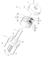
図1は、開閉方向規制機構10を適用した手動式のシャッター装置1を示す一部切欠正面図である。図2は、開閉方向規制機構10を示す分解斜視図である。図3は、図1のA−A線一部省略断面図である。図4は、図2のフランジ11を示す左側面図である。図5は、図2のブラケット12、2ウェイクラッチ13及び回転ダンパ14を示す右側面図である。図6は、図1のB−B線断面図である。
FIG. 1 is a partially cutaway front view showing a
シャッター装置1は、車庫や店舗等の大面積の開口部を上下に昇降して開閉するものである。シャッター装置1は、上下に昇降可能なスラット2と、スラット2を巻き取る巻取部材3と、巻取部材3の回転中心に配置された固定軸4と、を備えている。スラット2、巻取部材3及び固定軸4を収容する収容スペース5は、収容カバー5aで覆われており、風雨に曝されることなく保護されている。
The
スラット2は、上下に隣接して配置されたスラット部材2aが搖動軸2bを介してヒンジ結合されて構成されている。スラット2の上端は、巻取部材3に結合されており、巻取部材3の外周に巻き取られる構成になっている。スラット2の両端は、左右に立設されたガイドレール6の図示しない摺動溝内に収容されており、スラット2の昇降に伴うバタつきが抑制されるようになっている。
The
巻取部材3は、略円筒状に形成されている。具体的には、巻取部材3は、水平方向に延伸された4本のシャフト3aと、支持軸4に圧入嵌合されたベアリング3b、3cと、シャフト3aの一方端に接合されるとともにベアリング3bに外装されたホイール3dと、シャフト3aの他方端に接合されるとともにベアリング3cに外装されたホイール3eと、で構成されている。これにより、巻取部材3が巻取方向(開方向)D1に回転駆動されると、スラット2が巻取部材3に巻き取られて上昇し、巻取部材3が反巻取方向(閉方向)D2に回転駆動されると、スラット2が送り出されて下降するようになっている。なお、シャフト3aの本数は、4本に限定されるものではなく、2〜3本でも、5本以上であっても構わない。
The winding
固定軸4は、左右のガイドレール6の上部にそれぞれ設けられたシャッターブラケット7間に架設されており、固定軸4の両端は、それぞれシャッターブラケット7に固定支持されている。固定軸4には、トーションスプリング(ねじりコイルバネ)8が巻回されている。
The fixed
トーションスプリング8は、巻取部材3内に収容されている。トーションスプリング8の一方端は、ホイール3dに固定されており、他方端は、固定軸4に固定されている。トーションスプリング8は、ホイール3d対して巻取方向D1に付勢するようになっている。これにより、僅かな力でスラット2を上昇させることができる。
The
次に、開閉方向規制機構10の構造について、図面に基づいて説明する。開閉方向規制機構10は、固定軸4の端部に固着されたフランジ11と、フランジ11に隣接して配置されたブラケット12と、ブラケット12の側面に設けられた2ウェイクラッチ13と、を備えている。
Next, the structure of the opening / closing
フランジ11のブラケット12と対向する対向面11aには、内歯車11bが形成されている。フランジ11は、円板状に形成されており、ボルト孔11cに螺挿されたボルトBの先端が固定軸4に食い込むことにより、フランジ11が固定軸4に固着される。なお、符号11dは、固定軸4を挿通する挿通孔である。
An
ブラケット12は、円筒状に形成されており、中央の孔部12aにホイール3dの小径部3d’が挿通されている。ブラケット12のフランジ11と対向する一方側面12bには、2ウェイクラッチ13が設けられている。ブラケット12の他方側面12cには、ホイール3dと接合されている。したがって、ブラケット12は、ホイール3dを介して巻取部材3と一体で回転するようになっている。
The
2ウェイクラッチ13の入力軸13aには、クラッチ用遊星外歯車13bが設けられている。クラッチ用遊星外歯車13bは、フランジ11の内歯車11bと噛合可能になっている。ブラケット12がフランジ11に対して相対的に回転駆動されると、フランジ11の内歯車11aと2ウェイクラッチ13のクラッチ用遊星外歯車13bとが噛み合い、2ウェイクラッチ13の入力軸13aが回転する。
A clutch
2ウェイクラッチ13は、公知の構成であり、巻取部材3の巻回方向D1に沿った回転(正転)と巻取部材3の反巻回方向D2に沿った回転(逆転)の何れか一方を許容し、他方を制限するものである。2ウェイクラッチ13が制限する回転方向(ロック方向)は、既に回転が制限されている方向に所定閾値以上の外力が付与されることにより、任意に切換可能である。2ウェイクラッチ13の駆動方式として、摩擦切換式又は電気切換式が知られており、本発明でも何れを採用しても構わない。前者であれば、低コストで導入することができる。
The two-way clutch 13 has a known configuration, and either the rotation of the winding
開閉方向規制機構10は、回転ダンパ14を更に備えている。回転ダンパ14は、ブラケット12の一方側面12bに設けられている。回転ダンパ14の入力軸14aには、フランジ11の内歯車11bと噛合可能なダンパ用遊星外歯車14bが設けられている。回転ダンパ14は、公知の構成から成り、ダンパ用遊星外歯車14bを介して入力された入力軸14aの回転運動を制動する。回転ダンパ14は、例えば、入力軸14aの回転をオイルの粘性抵抗で制動するオイルダンパ等である。回転ダンパ14は、少なくとも、巻取部材3が巻取方向D1に回転する際に巻取部材3を減速させる無限回転ダンパが好ましい。回転ダンパ14に双方向無限回転ダンパを採用すれば、スラット2の昇降が制動されて、スラット2が緩やかに昇降される。また、回転ダンパ14に一方向無限回転ダンパを採用すれば、スラット2の上昇が制動されて、スラット2が緩やかに上昇されると共に、スラット2を下す際にスラット2の下降を制動する力(ダンパ力)が付与されないため軽い力で操作することができる。
The opening / closing
2ウェイクラッチ13及び回転ダンパ14は、固定軸4の軸方向から視て、固定軸4まわりに同心円上に配置されている。なお、開閉方向規制機構10に設けられる回転ダンパ14の設置個数は、1つに限定されるものではなく、2つ以上であっても構わない。回転ダンパ14を2つ設ける場合には、2ウェイクラッチ13を挟むように、回転ダンパ14が配置されるのが好ましい。
The two-way clutch 13 and the
2ウェイクラッチ13の側面13c及び回転ダンパ14の側面14cは、固定軸4の径方向から視て略面一に形成されている。これにより、クラッチ用遊星外歯車13b及び内歯車11bの噛み合い位置並びにダンパ用遊星外歯車14bと内歯車11bとの噛み合い位置が固定軸4の軸方向に位置ズレすることが抑制されるため、ブラケット12がフランジ11に対して略一定の位置で回転運動することができる。
The
なお、開閉方向規制機構10は、上述した構成に限定されるものではなく、例えば、フランジ11が巻取部材3と一体に可能に設けられ、ブラケット12が固定軸4に固着されたものであっても構わない。また、内歯車11bの代わりにブラケット11の外周に図示しない外歯車を刻設し、この外歯車とクラッチ用遊星外歯車13b及びダンパ用遊星外歯車14bとを噛合可能な構成であっても構わない。
The opening / closing
次に、開閉方向規制機構10の作用について説明する。図7(a)〜(d)は、開閉方向規制機構10の作用を示す一部切欠正面図である。なお、以下では、摩擦切換式の2ウェイクラッチ13を用いた場合を例に説明する。
Next, the operation of the opening / closing
スラット2が巻取部材3に巻き取られた状態では、図7(a)に示すように、2ウェイクラッチ13が巻取部材3の反巻取方向D2に沿った回転を制限する逆転阻止状態であり、且つ、トーションスプリング8の付勢力F1によって、巻取部材3には、巻取方向D1へのトルクが常に付与されているため、クラッチ用遊星外歯車13bが内歯車11bを噛み進むことが制限され、巻取部材3の反巻取方向D2への回転駆動は制限されている。
In a state where the
図7(b)に示すように、スラット2が巻取部材3に巻き取られた状態から、所定閾値以上の反巻取方向D2の外力F2が巻取部材3に付与されると、2ウェイクラッチ13の逆転阻止状態が解除され、巻取部材3の巻取方向D1に沿った回転を制限する正転阻止状態に移行し、巻取部材3の反巻取方向D2への回転駆動が可能となる。これにより、2ウェイクラッチ13のクラッチ用遊星外歯車13b及び回転ダンパ14のダンパ用遊星外歯車14bが自転しながら、2ウェイクラッチ13及び回転ダンパ14が入力軸4まわりに反巻取方向D2に沿って公転することにより、スラット2を降下させることができる。
As shown in FIG. 7B, when an external force F2 in the counter-winding direction D2 that is equal to or greater than a predetermined threshold is applied to the winding
次に、スラット2を任意の位置で停止させる場合には、スラット2を停止させたい位置で、スラット2を降下させる外力F2を取り除く。これは、図7(c)に示すように、トーションスプリング8の付勢力F1による巻取方向D1へのトルクが作用すると共に、2ウェイクラッチ13が巻取部材3の正転を制限するため、スラット2は外力F1が取り除かれた位置で停止するためである。
Next, when the
スラット2を一時停止状態から再び降下させる場合には、2ウェイクラッチ13は正転阻止状態であるから、反巻取方向D2の外力を付与するだけでスラット2を再び降下させることができる。
When the
スラット2を一時停止状態から上昇させる場合には、図7(d)に示すように、巻取部材3の巻取方向D1に所定閾値以上の外力F3が付与されると、2ウェイクラッチ13の正転阻止状態が解除されて、逆転阻止状態に移行する。そして、2ウェイクラッチ13の正転阻止状態解除後は、トーションスプリング8の付勢力F1により、2ウェイクラッチ13のクラッチ用遊星外歯車13b及び回転ダンパ14のダンパ用遊星外歯車14bが自転しながら、2ウェイクラッチ13及び回転ダンパ14が入力軸4まわりに巻取方向D1に沿って公転し、巻取部材3は巻取方向D1に回転駆動されることにより、スラット2を自動で上昇させることができる。
When raising the
また、回転ダンパ14は、トーションスプリング8が巻取部材3に付与する付勢力によってダンパ用遊星外歯車、巻取部材3が過剰に加速することを抑制する。例えば、巻取部材3の正転を制動する一方向無限回転ダンパを設置した場合には、スラット2の上昇動作が緩衝され、スラット2を静かに上昇させることができる。また、巻取部材3の正転及び逆転を制動する双方向無限回転ダンパを設置した場合には、スラット2の昇降が緩衝され、スラット2を静かに昇降させることができる。
Further, the
このようにして、本発明に係る開閉方向規制機構10は、2ウェイクラッチ13が回転を許容する方向に向かって巻取部材3に外力が付与されることにより、クラッチ用遊星外歯車13bが固定軸4まわりに公転し、巻取部材3及びブラケット12が固定軸4まわりに回転するため、スラット2を昇降させることができる。一方、2ウェイクラッチ13が回転を阻止する方向に向かって巻取部材3に外力が付与される場合には、クラッチ用遊星外歯車13bが固定軸4まわりに公転することが妨げられ、巻取部材3及びブラケット12の固定軸4まわりの回転が阻止されるため、スラット2の昇降が阻止される。また、2ウェイクラッチ13が許容するクラッチ用遊星外歯車13bの回転方向、即ち2ウェイクラッチ13の逆転阻止状態及び正転阻止状態は任意に切換自在なため、スラット2の上昇途中又は下降途中の何れであっても、スラット2を停止させることができる。
In this way, the opening / closing
次に、本発明の一実施例に係る吊引戸装置20について、図面に基づいて説明する。図8は、開閉方向規制機構30を適用した手動式の吊引戸20を示す模式図である。図9は、開閉方向規制機構30を示す要部拡大図である。
Next, the sliding
吊引戸装置20は、住居や病室等の出入口を水平方向にスライドして開閉するものである。吊引戸装置20は、略水平に設けられた吊りレール21と、吊りレール21に吊設された吊引戸22と、を備えている。
The sliding
吊りレール21は、出入口の上部に設けられ、水平方向に延伸されている。吊りレール21は、吊引戸22が閉じる閉方向D3に向かって僅かに下がるように傾斜している。吊りレール21には、ラック21a及び走行面21bが形成されている。
The
吊引戸22の上部左右端には、吊りレール21の走行面21b上を走行可能なライナー22aが設けられている。
開閉方向規制機構30は、吊引戸22の上部に配置されている。開閉方向規制機構30は、吊引戸22の上端に配置されたベース部材31と、ベース部材31の側面に配置された2ウェイクラッチ32と、を備えている。
The opening / closing
ベース部材31は、矩形状に形成されおり、吊引戸22の上端に接合され、吊引戸22と一体となってスライドするようになっている。
The
2ウェイクラッチ32は、ベース部材31の吊りレール21と対向する対向面31aに設けられている。2ウェイクラッチ32の入力軸32aには、吊りレール21のラック21aと噛合可能なクラッチ用ピニオン32bが設けられている。吊引戸22及びベース部材31が吊りレール21に対して相対的にスライドすると、吊りレール21のラック21aと2ウェイクラッチ32のクラッチ用ピニオン32bとが噛み合い、2ウェイクラッチ32の入力軸32aが回転する。
The two-way clutch 32 is provided on a facing
2ウェイクラッチ32は、公知の構成であり、吊引戸22が閉じる閉方向D3に沿ったスライド(閉動作)と吊引戸22が開く開方向D4に沿ったスライド(開動作)の何れか一方を許容し、他方を制限するものである。2ウェイクラッチ32が制限するスライドの向き(ロック方向)は、既にスライドが制限されている方向に所定閾値以上の外力が付与されることにより、任意に切換可能である。2ウェイクラッチ32の駆動方式として、摩擦切換式又は電気切換式が知られており、本発明でも何れを採用しても構わない。前者であれば、低コストで導入することができる。
The two-way clutch 32 has a known configuration, and either the slide along the closing direction D3 in which the hanging
また、開閉方向規制機構30は、2ウェイクラッチ32と隣り合うようにベース部材31の対向面31aに配置された回転ダンパ33を更に備えている。回転ダンパ33の入力軸33aに設けられたダンパ用ピニオン33bは、吊りレール21のラック21aと噛合可能になっている。回転ダンパ33は、例えば、入力軸33aの回転をオイルの粘性抵抗で制動するオイルダンパ等である。回転ダンパ33は、少なくとも、吊引戸22の閉方向D3へのスライドを減速させる無限回転ダンパが好ましい。回転ダンパ33に双方向無限回転ダンパを採用すれば、吊引戸22の開閉が制動されて、吊引戸22が緩やかに開閉される。また、回転ダンパ33に一方向無限回転ダンパを採用すれば、吊引戸22の閉動作が制動されて、吊引戸22が緩やかに閉じる。
The opening / closing
次に、開閉方向規制機構30の作用について説明する。図10(a)〜(d)は、開閉方向規制機構30の作用を示す模式図である。なお、以下では、摩擦切換式の2ウェイクラッチ32を用いた場合を例に説明する。
Next, the operation of the opening / closing
吊引戸22が閉じた状態では、図10(a)に示すように、2ウェイクラッチ32が吊引戸22の開方向D4に沿ったスライドを制限する開動作阻止状態であり、且つ、吊引戸22には閉方向D3への自重F4が作用しており、クラッチ用ピニオン32bがラック21aを噛み進むことが制限され、吊引戸22の開方向D4へのスライドが制限されている。
In the state where the
図10(b)に示すように、吊引戸22が閉じた状態から、所定閾値以上の開方向D4の外力F5が吊引戸22に付与されると、2ウェイクラッチ32の開動作阻止状態が解除され、吊引戸22の閉方向D3に沿ったスライドを制限する閉動作阻止状態に移行し、吊引戸22の開方向D4へのスライドが可能となる。これにより、吊引戸22を開くことができる。
As shown in FIG. 10B, when the external force F5 in the opening direction D4 that is equal to or greater than a predetermined threshold is applied to the hanging
次に、吊引戸22を任意の位置で停止させる場合には、吊引戸22を停止させたい位置で、吊引戸22に作用する外力F5を取り除く。これは、図10(c)に示すように、吊引戸22には自重F4が作用すると共に、2ウェイクラッチ32は吊引戸22の閉動作を制限するため、吊引戸22は外力が取り除かれた位置で停止するためである。
Next, when the
吊引戸22を一時停止状態から再び開く場合には、2ウェイクラッチ32は閉動作阻止状態であるから、吊引戸22に開方向D4の外力Fが付与されるだけで吊引戸22を再び開くことができる。
When the
吊引戸22を一時停止状態から閉じる場合には、図10(d)に示すように、所定閾値以上の閉方向D3の外力F6が吊引戸22に付与されると、2ウェイクラッチ32の閉動作阻止状態が解除されて、開動作阻止状態に移行する。そして、2ウェイクラッチ32の閉動作阻止状態解除後は、吊引戸22の自重F4により、吊引戸22を自動的に閉方向D3にスライドさせることができる。
When the
また、回転ダンパ33は、吊引戸22が過剰に加速することを抑制する。例えば、吊引戸22の閉方向D3へのスライドを制動する一方向無限回転ダンパを設置した場合には、吊引戸22の閉動作が緩衝され、吊引戸22を静かに閉じることができる。また、吊引戸22の開方向D3及び閉方向D4へのスライドを制動する双方向無限回転ダンパを設置した場合には、吊引戸22の開閉が緩衝され、吊引戸22を静かに開閉させることができる。
Moreover, the
このようにして、本発明に係る開閉方向規制機構30は、2ウェイクラッチ32がクラッチ用ピニオン32bの自転を許容する方向に向かって吊引戸22に外力が付与されることにより、2ウェイクラッチ32のクラッチ用ピニオン32bが吊りレール21のラック21aと噛み合って進むため、吊引戸22を開閉させることができる。一方、2ウェイクラッチ32がクラッチ用ピニオン32bの自転を阻止する方向に向かって吊引戸22に外力が付与される場合には、吊りレール21に対する吊引戸22の相対的なスライドが阻止されるため、吊引戸22のスライドが妨げられる。また、2ウェイクラッチ32が許容するクラッチ用ピニオン32bの回転方向、即ち2ウェイクラッチ32の開阻止状態及び閉阻止状態は任意に切換自在なため、吊引戸22の開動作中又は閉動作中の何れであっても、吊引戸22を停止させることができる。
In this way, the opening / closing
なお、本発明は、本発明の精神を逸脱しない限り種々の改変をなすことができ、そして、本発明が該改変されたものにも及ぶことは当然である。 The present invention can be variously modified without departing from the spirit of the present invention, and the present invention naturally extends to the modified ones.
本発明は、固定部材に対して相対的に移動する作動部材を所望の位置に位置決めするものであれば如何なるものに適用しても構わない。 The present invention may be applied to any member as long as the operating member that moves relative to the fixed member is positioned at a desired position.
1 ・・・ シャッター装置
2 ・・・ スラット
2a・・・ スラット部材
2b・・・ 搖動軸
3 ・・・ 巻取部材(作動部材)
3a・・・ シャフト
3b、3c・・・軸受
3d、3e・・・ホイール
4 ・・・ 固定軸(固定部材)
5 ・・・ 収容スペース
6 ・・・ ガイドレール
7 ・・・ シャッターブラケット
8 ・・・ トーションスプリング
10 ・・・ (シャッター装置の)開閉方向規制機構
11 ・・・ フランジ
11a・・・ (フランジの)対向面
11b・・・ 内歯車
11c・・・ ボルト孔
11d・・・ 挿通孔
12 ・・・ ブラケット
12a・・・ 孔部
12b・・・ 一方側面
12c・・・ 他方側面
13 ・・・ 2ウェイクラッチ
13a・・・ 入力軸
13b・・・ クラッチ用遊星外歯車
13c・・・ (2ウェイクラッチの)側面
14 ・・・ 回転ダンパ
14a・・・ 入力軸
14b・・・ ダンパ用遊星外歯車
14c・・・ (回転ダンパの)側面
20 ・・・ 吊引戸装置
21 ・・・ 吊りレール(固定部材)
21a・・・ ラック
22 ・・・ 吊引戸(作動部材)
30 ・・・ (吊引戸装置の)開閉方向規制機構
31 ・・・ ベース部材
31a・・・ (ベース部材の)対向面
32 ・・・ 2ウェイクラッチ
32a・・・ 入力軸
32b・・・ クラッチ用ピニオン
33 ・・・ 回転ダンパ
33a・・・ 入力軸
33b・・・ ダンパ用ピニオン
D1 ・・・ 巻取方向
D2 ・・・ 反巻取方向
D3 ・・・ 閉方向
D4 ・・・ 開方向
DESCRIPTION OF
3a ...
5 ・ ・ ・
21a ...
30 ... Opening / closing direction regulating mechanism 31 (of the sliding door device) ...
Claims (9)
前記巻取部材又は前記固定軸の一方に取り付けられたブラケットと、該ブラケットに隣接配置されると共に前記巻取部材又は前記固定軸の他方に取り付けられたフランジと、前記ブラケットの前記フランジに対向する対向面に配置された2ウェイクラッチと、を備え、
前記フランジに形成された歯車と前記2ウェイクラッチの入力軸に装着されたクラッチ用外歯車とが噛合可能に配置され、
前記2ウェイクラッチは、前記巻取部材の巻取方向に沿った前記クラッチ用外歯車の自転を許容して反巻取方向に沿った前記クラッチ用外歯車の自転を阻止する逆転阻止状態と、前記巻取部材の巻取方向に沿った前記クラッチ用外歯車の自転を阻止して反巻取方向に沿った前記クラッチ用外歯車の自転を許容する正転阻止状態とを切換可能に設けられていることを特徴とする手動式シャッター装置の開閉方向規制機構。 A fixed shaft extending substantially horizontally; a winding member that is rotatably provided on the fixed shaft and winds up the slat; and the winding shaft that is built in the winding member and winds up the slat. In the opening / closing direction regulating mechanism of the manual shutter device comprising a torsion spring for biasing the member,
A bracket attached to one of the winding member or the fixed shaft, a flange disposed adjacent to the bracket and attached to the other of the winding member or the fixed shaft, and opposed to the flange of the bracket A two-way clutch disposed on the opposing surface;
The gear formed on the flange and the clutch external gear mounted on the input shaft of the two-way clutch are arranged so as to be meshable,
The two-way clutch is configured to prevent reverse rotation of the clutch external gear along the anti-winding direction while allowing rotation of the clutch external gear along the winding direction of the winding member; It is provided so as to be switchable between a forward rotation prevention state in which rotation of the external gear for clutch along the winding direction of the winding member is prevented and rotation of the external gear for clutch along the anti-winding direction is allowed. A mechanism for restricting the opening / closing direction of a manual shutter device.
前記フランジは、前記固定軸に固着されていることを特徴とする請求項1記載の手動式シャッター装置の開閉方向規制機構。 The bracket is formed in a cylindrical shape, is externally fitted to the fixed shaft and is provided to be rotatable integrally with the winding member,
2. The opening / closing direction regulating mechanism for a manual shutter device according to claim 1, wherein the flange is fixed to the fixed shaft.
前記吊引戸の上端にベース部材を固着し、前記ベース部材の前記吊りレールと対向する対向面に2ウェイクラッチを配置し、
前記吊りレールに形成されたラックと前記2ウェイクラッチの入力軸に装着されたクラッチ用ピニオンとが噛合可能に配置され、
前記2ウェイクラッチは、前記吊引戸の閉方向へのスライドに応じた前記クラッチ用ピニオンの自転を許容して前記吊引戸の開方向へのスライドに応じた前記クラッチ用ピニオンの自転を阻止する開阻止状態と、前記吊引戸の閉方向へのスライドに応じた前記クラッチ用ピニオンの自転を阻止して前記吊引戸の開方向へのスライドに応じた前記クラッチ用ピニオンの自転を許容する閉阻止状態とを切換可能に設けられていることを特徴とする吊引戸装置の開閉方向規制機構。 In the opening / closing direction regulating mechanism of the hanging door device, the hanging door is hung on a hanging rail provided substantially horizontally, and a liner capable of traveling on the hanging rail is provided on the hanging door.
A base member is fixed to the upper end of the suspension door, and a two-way clutch is disposed on the facing surface of the base member facing the suspension rail,
A rack formed on the suspension rail and a clutch pinion mounted on the input shaft of the two-way clutch are arranged so as to be able to mesh with each other,
The two-way clutch is configured to permit the rotation of the clutch pinion according to the sliding of the suspension door in the closing direction and to prevent the rotation of the clutch pinion according to the sliding of the suspension door in the opening direction. A blocking state and a closing blocking state that prevents rotation of the clutch pinion in response to sliding in the closing direction of the hanging door and allows rotation of the clutch pinion in response to sliding in the opening direction of the hanging door. And an opening / closing direction regulating mechanism for the sliding door device.
Priority Applications (1)
| Application Number | Priority Date | Filing Date | Title |
|---|---|---|---|
| JP2016119420A JP6828873B2 (en) | 2016-06-15 | 2016-06-15 | Opening / closing direction regulation mechanism of manual shutter device and opening / closing direction regulation mechanism of hanging sliding door device |
Applications Claiming Priority (1)
| Application Number | Priority Date | Filing Date | Title |
|---|---|---|---|
| JP2016119420A JP6828873B2 (en) | 2016-06-15 | 2016-06-15 | Opening / closing direction regulation mechanism of manual shutter device and opening / closing direction regulation mechanism of hanging sliding door device |
Publications (2)
| Publication Number | Publication Date |
|---|---|
| JP2017223051A true JP2017223051A (en) | 2017-12-21 |
| JP6828873B2 JP6828873B2 (en) | 2021-02-10 |
Family
ID=60687806
Family Applications (1)
| Application Number | Title | Priority Date | Filing Date |
|---|---|---|---|
| JP2016119420A Active JP6828873B2 (en) | 2016-06-15 | 2016-06-15 | Opening / closing direction regulation mechanism of manual shutter device and opening / closing direction regulation mechanism of hanging sliding door device |
Country Status (1)
| Country | Link |
|---|---|
| JP (1) | JP6828873B2 (en) |
Cited By (2)
| Publication number | Priority date | Publication date | Assignee | Title |
|---|---|---|---|---|
| CN110409985A (en) * | 2019-09-10 | 2019-11-05 | 襄阳市思想机电科技有限公司 | A kind of tackle system of unilateral gate |
| CN110409985B (en) * | 2019-09-10 | 2024-04-26 | 襄阳市思想机电科技有限公司 | Pulley system of one-way door |
Families Citing this family (1)
| Publication number | Priority date | Publication date | Assignee | Title |
|---|---|---|---|---|
| WO2023027719A1 (en) * | 2021-08-27 | 2023-03-02 | Illinois Tool Works Inc. | Planetary gear dampener |
Citations (4)
| Publication number | Priority date | Publication date | Assignee | Title |
|---|---|---|---|---|
| JPS5641037Y2 (en) * | 1977-06-30 | 1981-09-25 | ||
| JP2003082922A (en) * | 2001-09-04 | 2003-03-19 | Atom Livin Tech Co Ltd | Self-closing sliding door device and self-closing sliding door unit |
| JP2005114072A (en) * | 2003-10-08 | 2005-04-28 | Izumi-Cosmo Co Ltd | Coil spring device and roll screen device using the same |
| JP2010174491A (en) * | 2009-01-29 | 2010-08-12 | Taiyo Ltd | Braking device of sliding door equipment, and sash roller device with the braking mechanism |
-
2016
- 2016-06-15 JP JP2016119420A patent/JP6828873B2/en active Active
Patent Citations (4)
| Publication number | Priority date | Publication date | Assignee | Title |
|---|---|---|---|---|
| JPS5641037Y2 (en) * | 1977-06-30 | 1981-09-25 | ||
| JP2003082922A (en) * | 2001-09-04 | 2003-03-19 | Atom Livin Tech Co Ltd | Self-closing sliding door device and self-closing sliding door unit |
| JP2005114072A (en) * | 2003-10-08 | 2005-04-28 | Izumi-Cosmo Co Ltd | Coil spring device and roll screen device using the same |
| JP2010174491A (en) * | 2009-01-29 | 2010-08-12 | Taiyo Ltd | Braking device of sliding door equipment, and sash roller device with the braking mechanism |
Cited By (2)
| Publication number | Priority date | Publication date | Assignee | Title |
|---|---|---|---|---|
| CN110409985A (en) * | 2019-09-10 | 2019-11-05 | 襄阳市思想机电科技有限公司 | A kind of tackle system of unilateral gate |
| CN110409985B (en) * | 2019-09-10 | 2024-04-26 | 襄阳市思想机电科技有限公司 | Pulley system of one-way door |
Also Published As
| Publication number | Publication date |
|---|---|
| JP6828873B2 (en) | 2021-02-10 |
Similar Documents
| Publication | Publication Date | Title |
|---|---|---|
| US6588480B2 (en) | Counter wrap cord drive | |
| AU2011326816C1 (en) | Modular anti-reversible power spring apparatus and method | |
| US20170298691A1 (en) | Shielding device | |
| JP3961668B2 (en) | Sliding door closer | |
| JP6828873B2 (en) | Opening / closing direction regulation mechanism of manual shutter device and opening / closing direction regulation mechanism of hanging sliding door device | |
| US20220195798A1 (en) | Opening/closing direction restriction mechanism for manual shutter device and opening/closing direction restriction mechanism for suspended sliding door | |
| CA3004735A1 (en) | Cable drum construction for multiple, horizontal, articulating panel door assembly | |
| JP6050911B1 (en) | Overdoor opening and closing device | |
| JP2005068755A (en) | Shutter device | |
| US20210214974A1 (en) | Power transfer device for a rolling door operator | |
| KR100815616B1 (en) | An apparatus for opening and shutting a revolving door | |
| JP4184286B2 (en) | Shutter curtain opening / closing device for shutter device | |
| JPH0972174A (en) | Shutter | |
| JPH0211593Y2 (en) | ||
| AU648532B2 (en) | A drive system motor operated garage doors | |
| JP2002155686A (en) | Architectural shutter | |
| US20210214999A1 (en) | Limit position safety device for a rolling door | |
| KR200435329Y1 (en) | An apparatus for opening and shutting a revolving door | |
| JP5211360B2 (en) | Sliding door closer | |
| KR20210056429A (en) | Electromechanical actuators and home automation equipment incorporating such actuators | |
| JPH0711672Y2 (en) | Lifting cord winding structure for lifting screen opening / closing device | |
| JP2006257857A (en) | Winding member structure with return spring of opening and closing device | |
| JPH0330558Y2 (en) | ||
| JPH05295974A (en) | Brake releaser of motor-driven shutter | |
| JP2016008498A (en) | Shielding device |
Legal Events
| Date | Code | Title | Description |
|---|---|---|---|
| A621 | Written request for application examination |
Free format text: JAPANESE INTERMEDIATE CODE: A621 Effective date: 20190527 |
|
| A131 | Notification of reasons for refusal |
Free format text: JAPANESE INTERMEDIATE CODE: A131 Effective date: 20200616 |
|
| A521 | Request for written amendment filed |
Free format text: JAPANESE INTERMEDIATE CODE: A523 Effective date: 20200724 |
|
| TRDD | Decision of grant or rejection written | ||
| A01 | Written decision to grant a patent or to grant a registration (utility model) |
Free format text: JAPANESE INTERMEDIATE CODE: A01 Effective date: 20210105 |
|
| A61 | First payment of annual fees (during grant procedure) |
Free format text: JAPANESE INTERMEDIATE CODE: A61 Effective date: 20210106 |
|
| R150 | Certificate of patent or registration of utility model |
Ref document number: 6828873 Country of ref document: JP Free format text: JAPANESE INTERMEDIATE CODE: R150 |
|
| R250 | Receipt of annual fees |
Free format text: JAPANESE INTERMEDIATE CODE: R250 |