JP2017222367A - Sheet feeding device and feeding method - Google Patents
Sheet feeding device and feeding method Download PDFInfo
- Publication number
- JP2017222367A JP2017222367A JP2016117014A JP2016117014A JP2017222367A JP 2017222367 A JP2017222367 A JP 2017222367A JP 2016117014 A JP2016117014 A JP 2016117014A JP 2016117014 A JP2016117014 A JP 2016117014A JP 2017222367 A JP2017222367 A JP 2017222367A
- Authority
- JP
- Japan
- Prior art keywords
- sheet
- feeding
- peeling
- holding member
- adhesive sheet
- Prior art date
- Legal status (The legal status is an assumption and is not a legal conclusion. Google has not performed a legal analysis and makes no representation as to the accuracy of the status listed.)
- Pending
Links
Images

Abstract
Description
本発明は、シート供給装置および供給方法に関する。 The present invention relates to a sheet supply apparatus and a supply method.
従来、帯状の剥離シートに仮着された接着シートを所定の供給位置に供給するシート供給装置が採用されたシート貼付装置において、原反に繰出力を付与する繰出力付与手段と剥離シートとのスリップを防止する技術が知られている(例えば、特許文献1参照)。 Conventionally, in a sheet sticking apparatus in which a sheet supply device that supplies an adhesive sheet temporarily attached to a strip-shaped release sheet to a predetermined supply position is employed, a repetitive output applying means for applying a repetitive output to an original fabric and a release sheet A technique for preventing slip is known (for example, see Patent Document 1).
しかしながら、特許文献1に記載された従来のシート供給装置は、ドライブローラおよびピンチローラからなる保持部材で保持した剥離紙(剥離シート)に対し、当該保持部材を相対移動させることでラベル原反(原反)を繰り出す構成が採用されているため、ドライブローラの回転開始直後やラベル原反の繰出中に、極少量ではあるがドライブローラと剥離紙とがスリップを起こして接着シートの供給遅れが発生し、被着体の所定位置に接着シートを貼付できなくなるという不都合が発生する。このような不都合は、ドライブローラを高速で回転させると顕著化する。 However, the conventional sheet supply apparatus described in Patent Document 1 moves the holding member relative to the release paper (release sheet) held by the holding member composed of a drive roller and a pinch roller, thereby moving the label original fabric ( Since the structure that feeds out the original material is adopted, the drive roller and the release paper slip even if the drive roller starts rotating or during the feeding of the label material, causing a delay in feeding the adhesive sheet. This causes a disadvantage that the adhesive sheet cannot be applied to a predetermined position of the adherend. Such inconvenience becomes noticeable when the drive roller is rotated at a high speed.
本発明の目的は、接着シートの供給遅れを防止することができるシート供給装置および供給方法を提供することにある。 An object of the present invention is to provide a sheet feeding apparatus and a feeding method that can prevent a delay in feeding an adhesive sheet.
前記目的を達成するために、本発明のシート供給装置は、帯状の剥離シートの一方の面に接着シートが仮着された原反を繰り出す繰出手段と、前記繰出手段で繰り出された原反における剥離シートから前記接着シートを剥離して所定の供給位置に供給する剥離手段とを備え、前記繰出手段は、前記接着シートが剥離された剥離シートを保持部材で保持し、当該剥離シートに張力を付与して前記原反を繰り出す繰出力付与手段を備え、前記繰出力付与手段は、前記剥離シートに対する前記保持部材の保持位置を一定位置に維持したまま、当該保持部材および前記剥離手段を相対移動させて前記原反を繰り出すことを特徴とする。 In order to achieve the above object, a sheet feeding apparatus according to the present invention includes a feeding unit that feeds an original fabric in which an adhesive sheet is temporarily attached to one surface of a strip-shaped release sheet, and a raw fabric fed by the feeding unit. Peeling means for peeling off the adhesive sheet from the release sheet and supplying the peeled sheet to a predetermined supply position, and the feeding means holds the release sheet from which the adhesive sheet has been peeled off by a holding member, and applies tension to the release sheet. A feed output giving means for feeding and feeding the original fabric, wherein the feed output giving means relatively moves the holding member and the peeling means while maintaining a holding position of the holding member with respect to the release sheet at a fixed position. And feeding out the original fabric.
この際、本発明のシート供給装置では、前記繰出力付与手段は、前記接着シートが剥離された剥離シートを前記保持部材で回収することが好ましい。
また、本発明のシート供給装置では、前記繰出力付与手段は、前記保持部材の起点となる所定の起点位置から、当該起点位置よりも前記剥離手段から離間した離間位置に向かう一方向に当該保持部材を移動させることで、前記原反を繰り出し可能に設けられ、前記一方向のみに前記保持部材を移動させる間で、前記接着シートを複数枚供給可能に設けられていることが好ましい。
さらに、本発明のシート供給装置では、少なくとも前記繰出力付与手段の動作を制御する制御手段を備え、当該制御手段は、1枚の前記接着シートを供給するために必要な前記保持部材の移動量を基にして、前記起点位置から前記離間位置までの間で前記保持部材を前記一方向のみに移動させた際、供給できる前記接着シートの枚数を算出可能に設けられていることが好ましい。
At this time, in the sheet supply apparatus of the present invention, it is preferable that the feeding output providing unit collects the release sheet from which the adhesive sheet has been released with the holding member.
In the sheet supply apparatus of the present invention, the feed output imparting unit holds the holding output in a direction from a predetermined starting position serving as a starting point of the holding member toward a separated position that is farther from the peeling unit than the starting position. By moving the member, it is preferable that the original fabric can be fed out, and a plurality of the adhesive sheets can be supplied while the holding member is moved only in the one direction.
Furthermore, the sheet supply apparatus according to the present invention further includes a control unit that controls at least the operation of the feed output applying unit, and the control unit moves the holding member necessary for supplying one adhesive sheet. It is preferable that the number of the adhesive sheets that can be supplied when the holding member is moved only in the one direction from the starting position to the separated position is calculated.
一方、本発明のシート供給方法は、帯状の剥離シートの一方の面に接着シートが仮着された原反を繰り出す繰出工程と、前記繰出工程で繰り出された原反における剥離シートから前記接着シートを剥離手段で剥離して所定の供給位置に供給する剥離工程とを有し、前記繰出工程は、前記接着シートが剥離された剥離シートを保持部材で保持し、当該剥離シートに張力を付与して前記原反を繰り出す繰出力付与工程を有し、前記繰出力付与工程は、前記剥離シートに対する前記保持部材の保持位置を一定位置に維持したまま、当該保持部材および前記剥離手段を相対移動させて前記原反を繰り出すことを特徴とする。 On the other hand, the sheet supply method of the present invention includes a feeding step of feeding a raw material in which an adhesive sheet is temporarily attached to one surface of a strip-shaped peeling sheet, and the adhesive sheet from the peeling sheet in the raw material fed in the feeding step. A peeling step of peeling the substrate by a peeling means and supplying it to a predetermined supply position. The feeding step holds the release sheet from which the adhesive sheet has been peeled off by a holding member, and applies tension to the release sheet. A feed output applying step for feeding out the original fabric, wherein the feed output applying step moves the holding member and the peeling means relative to each other while maintaining the holding position of the holding member with respect to the release sheet at a fixed position. The original fabric is fed out.
請求項1によれば、保持部材で保持した剥離シートに対し、当該保持部材を相対移動させることなく原反を繰り出すので、保持部材と剥離シートとがスリップを起こすことがなくなり、接着シートの供給遅れを防止することができる。 According to the first aspect, since the original fabric is fed out without moving the holding member relative to the release sheet held by the holding member, the holding member and the release sheet are prevented from slipping, and the adhesive sheet is supplied. Delay can be prevented.
請求項2によれば、剥離シートを回収する部材を別途設ける必要がなくなり、装置の大型化を防止することができる。
請求項3によれば、保持部材を起点位置に復帰させる動作を少なくすることができ、動作の簡略化を図ることができる。
請求項4によれば、効率よく接着シートを供給することができる。
According to the second aspect, it is not necessary to separately provide a member for collecting the release sheet, and an increase in the size of the apparatus can be prevented.
According to the third aspect, the operation of returning the holding member to the starting position can be reduced, and the operation can be simplified.
According to the fourth aspect, the adhesive sheet can be supplied efficiently.
以下、本発明の一実施形態を図面に基づいて説明する。
なお、本実施形態におけるX軸、Y軸、Z軸は、それぞれが直交する関係にあり、X軸およびY軸は、所定平面内の軸とし、Z軸は、前記所定平面に直交する軸とする。さらに、本実施形態では、Y軸と平行な図1中手前方向から観た場合を基準とし、方向を示した場合、「上」がZ軸の矢印方向で「下」がその逆方向、「左」がX軸の矢印方向で「右」がその逆方向、「前」がY軸と平行な図1中手前方向で「後」がその逆方向とする。
Hereinafter, an embodiment of the present invention will be described with reference to the drawings.
In this embodiment, the X axis, the Y axis, and the Z axis are orthogonal to each other, the X axis and the Y axis are axes in a predetermined plane, and the Z axis is an axis that is orthogonal to the predetermined plane. To do. Furthermore, in the present embodiment, when viewed from the front side in FIG. 1 parallel to the Y axis, when indicating the direction, “up” is the arrow direction of the Z axis and “down” is the opposite direction, “ The “left” is the arrow direction of the X axis, “right” is the opposite direction, “front” is the front direction in FIG. 1 parallel to the Y axis, and “rear” is the opposite direction.
図1において、シート供給装置10は、帯状の剥離シートRLの一方の面に接着シートASが仮着された原反RSを繰り出す繰出手段20と、繰出手段20で繰り出された原反RSにおける剥離シートRLから接着シートASを剥離して所定の供給位置SPに供給する剥離手段としての剥離板30と、当該シート供給装置10の全体的な動作を制御するパーソナルコンピュータやシーケンサ等の図示しない制御手段とを備え、剥離板30で剥離された接着シートASを被着体としての半導体ウエハ(以下、単に「ウエハ」ともいう)WFに押圧して貼付する押圧手段としての押圧ローラ40の側方であって、ウエハWFを支持して搬送する搬送手段50の上方に配置されている。
In FIG. 1, the
繰出手段20は、原反RSを支持する支持ローラ21と、原反RSを案内するガイドローラ22と、接着シートASが剥離された剥離シートRLを保持部材としての巻取ローラ23Eで保持し、当該剥離シートRLに張力を付与して原反RSを繰り出す繰出力付与手段23とを備えている。
繰出力付与手段23は、駆動機器としてのリニアモータ23Aのスライダ23Bに支持された駆動機器としての回動モータ23Cと、回動モータ23Cの出力軸23Dに支持された巻取ローラ23Eとを備え、剥離シートRLに対する巻取ローラ23Eの保持位置を一定位置に維持したまま、当該巻取ローラ23Eおよび剥離板30を相対移動させて原反RSを繰り出す構成になっている。
本実施形態の場合、繰出力付与手段23は、巻取ローラ23Eの起点となる所定の起点位置AAから、当該起点位置AAよりも剥離板30から離間した離間位置BBに向かう一方向ADに当該巻取ローラ23Eを移動させることで、原反RSを繰り出すようになっている。なお、この場合の離間位置BBとは、剥離板30に対するリニアモータ23Aの遠い方のストロークエンドにスライダ23Bが位置したときに、巻取ローラ23Eが配置される位置である。
The feeding means 20 holds the
The repetitive output giving means 23 includes a rotating
In the case of this embodiment, the feed
搬送手段50は、駆動機器としてのリニアモータ51のスライダ51Aに支持され、減圧ポンプや真空エジェクタ等の図示しない減圧手段によってウエハWFを支持可能な支持面52Aを有する支持テーブル52を備えている。
The transfer means 50 includes a support table 52 that is supported by a
以上のシート供給装置10の動作を説明する。
先ず、図1中実線で示す初期位置に各部材が配置されたシート供給装置10に対し、作業者が原反RSを同図に示すようにセットし、当該原反RSのリード端部の剥離シートRLを巻取ローラ23Eに固定した後、操作パネルやパーソナルコンピュータ等の図示しない操作手段を介して図示しない制御手段に自動運転開始の信号を入力する。なお、本実施形態の場合、巻取ローラ23Eに剥離シートRLを固定した部分が剥離シートRLに対する巻取ローラ23Eの保持位置となる。次いで、繰出手段20が回動モータ23Cを駆動し、巻取ローラ23Eで剥離シートRLを巻き取ることで原反RSを繰り出し、図1に示すように、先頭の接着シートASの先端が剥離板30の先端部で剥離シートRLから所定長さ剥離されたことがカメラ等の撮像手段や光学センサ等の図示しない検知手段に検知されると、回動モータ23Cの駆動を停止し、スタンバイ状態となる。
The operation of the above
First, the operator sets the original fabric RS as shown in the figure with respect to the
そして、人手または多関節ロボットやベルトコンベア等の図示しない搬送手段によって、ウエハWFが支持面52A上に載置されると、搬送手段50が図示しない減圧手段を駆動し、ウエハWFを吸着保持した後、リニアモータ51を駆動し、支持テーブル52を左方へ移動させる。次いで、ウエハWFの左端部が所定の位置に到達したことがカメラ等の撮像手段や光学センサ等の図示しない検知手段に検知されると、繰出手段20が回動モータ23Cの駆動を停止させた状態でリニアモータ23Aを駆動し、ウエハWFの左方への搬送速度と接着シートASの左方への供給速度とが同じ速度となるように巻取ローラ23Eを一方向ADへ移動させる。このとき、剥離シートRLに対する巻取ローラ23Eの保持位置が一定位置に維持されたまま、当該巻取ローラ23Eおよび剥離板30が相互に離間する方向に相対移動されるので、巻取ローラ23Eと剥離シートRLとがスリップを起こすことはない。これにより、接着シートASは、図1中二点鎖線で示すように、押圧ローラ40によってウエハWFの上面に押圧されて貼付され、その全体がウエハWFに貼付された後、次の接着シートASの先端が剥離板30の先端部で剥離シートRLから所定長さ剥離されたことが図示しない検知手段に検知されると、繰出手段20がリニアモータ23Aの駆動を停止し、再びスタンバイ状態となる。このとき、巻取ローラ23Eは、図1の左側の二点鎖線で示す位置で停止する。そして、図示しない制御手段は、1枚の接着シートASを供給するために必要な巻取ローラ23Eの移動量を基にして、起点位置AAから離間位置BBまでの間で巻取ローラ23Eを一方向ADのみに移動させた際、供給できる接着シートASの枚数を算出する。本実施形態の場合、1枚の接着シートASを供給するのに必要な巻取ローラ23Eの移動量が310mmとされ、起点位置AAから離間位置BBまでの距離が750mmとされているので、図示しない制御手段は、一方向ADのみに巻取ローラ23Eを移動させた際、接着シートASを2枚供給できると判断する。なお、接着シートAS全体が貼付されたウエハWFが押圧ローラ40の左方所定位置に到達したことがカメラ等の撮像手段や光学センサ等の図示しない検知手段に検知されると、搬送手段50がリニアモータ51および図示しない減圧手段の駆動を停止する。
Then, when the wafer WF is placed on the
その後、図示しない搬送手段が、接着シートASが貼付されたウエハWFを次の工程に搬送した後、搬送手段50がリニアモータ51を駆動し、支持テーブル52を初期位置に復帰させ、再度、上記と同等の動作を繰り返し、2枚目のウエハWFに次の接着シートASを貼付する動作が行われる。このとき、巻取ローラ23Eは、図1の左側の二点鎖線で示す位置から同図の右側の二点鎖線で示す位置まで移動する。これにより、繰出力付与手段23は、一方向ADのみに巻取ローラ23Eを移動させる間で、接着シートASを複数枚供給することとなる。そして、図示しない搬送手段が、次の接着シートASが貼付された2枚目のウエハWFを次の工程に搬送すると、繰出手段20がリニアモータ23Aおよび回動モータ23Cを駆動し、巻取ローラ23Eで剥離シートRLを巻回して回収しながら当該巻取ローラ23Eを初期位置に復帰させる。これにより、接着シートASが剥離された剥離シートRLを繰出力付与手段23が巻取ローラ23Eで回収することとなる。このとき、原反RSが支持ローラ21側から繰り出されるようなことがあれば、図1中二点鎖線で示すように、当該支持ローラ21の回転を抑制する駆動機器やクラッチ等の回転防止手段21Aや、駆動機器としての図示しないチャックシリンダで原反RSを把持して当該原反RSの繰出しを防止する繰出防止手段等の原反繰出防止手段を設けてもよい。その後、搬送手段50がリニアモータ51を駆動し、支持テーブル52を初期位置に復帰させ、以降上記同様の動作が繰り返される。
After that, after a transfer unit (not shown) transfers the wafer WF with the adhesive sheet AS attached thereto to the next step, the
以上のような実施形態によれば、巻取ローラ23Eで保持した剥離シートRLに対し、当該巻取ローラ23Eを相対移動させることなく原反RSを繰り出すので、巻取ローラ23Eと剥離シートRLとがスリップを起こすことがなくなり、接着シートASの供給遅れを防止することができる。
According to the embodiment as described above, since the raw fabric RS is fed out without moving the take-up
本発明における手段および工程は、それら手段および工程について説明した動作、機能または工程を果たすことができる限りなんら限定されることはなく、まして、前記実施形態で示した単なる一実施形態の構成物や工程に全く限定されることはない。例えば、剥離手段は、繰出手段で繰り出された原反における剥離シートから接着シートを剥離して所定の供給位置に供給可能なものであれば、出願当初の技術常識に照らし合わせ、その技術範囲内のものであればなんら限定されることはない(他の手段および工程も同様でありその説明は省略する)。 The means and steps in the present invention are not limited in any way as long as they can perform the operations, functions, or steps described with respect to those means and steps. The process is not limited at all. For example, if the peeling means is capable of peeling the adhesive sheet from the peeling sheet in the raw material fed by the feeding means and supplying it to a predetermined supply position, it is within the technical scope in light of the technical common sense at the beginning of the application. (The other means and steps are the same, and the description thereof is omitted).
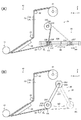
繰出力付与手段23は、図2(A)に示すように、回動モータ23Cをリニアモータ23Aのスライダ23Bから独立させ、一対のチャック部材23Fを備えた保持部材である駆動機器としてのチャックシリンダ23Gをスライダ23Bで支持する構成としてもよい。この場合、繰出手段20がチャックシリンダ23Gおよびリニアモータ23Aを駆動し、一対のチャック部材23Fで剥離シートRLを把持してチャックシリンダ23Gを一方向ADへ移動させて原反RSを繰り出し、次いで、一対のチャック部材23Fによる剥離シートRLの把持を解除した後、リニアモータ23Aおよび回動モータ23Cを駆動し、巻取ローラ23Eで剥離シートRLを巻回して回収しながらチャックシリンダ23Gを初期位置に復帰させればよい。この場合、チャック部材23Fで剥離シートRLを把持した部分が剥離シートRLに対するチャックシリンダ23Gの保持位置となる。なお、回動モータ23Cを支持する保持アームを設け、当該保持アームをスライダ23Bで支持するように構成してもよい。
また、繰出力付与手段23は、図2(B)に示すように、駆動機器としての回動モータ23Hの出力軸23Jで揺動アーム23Kを支持し、当該揺動アーム23Kの先端で回動モータ23Cを支持してもよい。この場合、繰出手段20が回動モータ23Cの駆動を停止させた状態で回動モータ23Hを駆動し、起点位置AAから離間位置BBに向かう一方向BD(反時計回転方向)に巻取ローラ23Eを移動させることで、原反RSを繰り出した後、回動モータ23C、23Hを駆動し、巻取ローラ23Eで剥離シートRLを巻回して回収しながら当該巻取ローラ23Eを初期位置に復帰させればよい。なお、図2(B)に示す繰出力付与手段23の場合、回動モータ23Hの有効移動量(揺動アーム23Kの回転角度)を大きくすることで、一方向BDのみに巻取ローラ23Eを移動させる間で、接着シートASを複数枚供給するようにしてもよい。この場合の離間位置BBとは、回動モータ23Hを駆動し、揺動アーム23Kを回転させたときに、剥離板30に対して巻取ローラ23Eが最も遠く離れた位置である。
As shown in FIG. 2 (A), the repetitive output giving means 23 is a chuck cylinder as a drive device that is a holding member having a pair of
Further, as shown in FIG. 2 (B), the feed output giving means 23 supports the
繰出手段20は、剥離シートRLに仮着された帯状の接着シート基材に複数の閉ループ状の切込が形成されることで、その内側が接着シートASとされた原反を繰り出してもよいし、帯状の接着シート基材が剥離シートRLに仮着された原反が採用された場合、切断手段により、接着シート基材を所定形状に切断してその内側を接着シートASとしてもよいし、接着シートASを剥離シートRLから剥離する際、原反RSに所定の張力が付与されるように回動モータ23Cや回転防止手段21Aのトルク制御を行ってもよいし、支持ローラ21やガイドローラ22等の各ローラの代わりに板状部材やシャフト部材等で原反RSや剥離シートRLを支持したり案内したりしてもよいし、原反RSを巻回することなく例えばファンフォールド折りにして支持してもよいし、剥離シートRLを巻回することなく例えばファンフォールド折りにしたり、シュレッダ等で切り刻んだりして回収してもよいし、保持部材で剥離シートRLを回収しなくてもよい。
繰出力付与手段23は、一方向ADやBDのみに巻取ローラ23Eやチャックシリンダ23Gを移動させる間で、接着シートASを1枚繰り出すように構成してもよいし、その間で接着シートASを3枚以上繰り出すように構成してもよいし、リニアモータ23Aのストローク(起点位置AAから離間位置BBまでの距離)は、750mm以下でもよいし、750mm以上でもよく、少なくとも、採用される接着シートASを1枚供給するのに必要な巻取ローラ23Eの移動量以上の長さであればよいし、巻取ローラ23Eやチャックシリンダ23Gを移動させずにまたは移動させつつ、剥離板30を移動させて原反RSを繰り出す構成でもよいし、図1および図2(B)に示した巻取ローラ23Eで剥離シートRLを巻回して回収しながら、当該巻取ローラ23Eと剥離板30とを相対移動させることで原反RSを繰り出す構成としてもよいし、巻取ローラ23Eやチャックシリンダ23Gを上下方向や、当該上下方向に対して傾斜した斜め方向を一方向として原反RSを繰り出す構成としてもよいし、巻取ローラ23Eを複数の部材で構成し、それらが駆動機器によって離間接近するようにしておき、それら複数の部材が相互に接近することで剥離シートRLを把持するようにしてもよいし、図2(A)に示したチャックシリンダ23Gを駆動機器としての回動モータの出力軸で支持し、当該回動モータをリニアモータ23Aのスライダ23Bで支持する構成とし、チャック部材23Fで剥離シートRLを巻回して回収するようにしてもよく、この場合、巻取ローラ23Eを省略できる。
保持部材への剥離シートRLの固定は、接着剤、粘着剤、接着テープ、粘着テープ、両面接着テープ、両面粘着テープ、クリップ、ステープラ、釘、溶接、溶着、磁着、結束、把持、引掛け等どのような固定の仕方でもよい。
The feeding means 20 may feed out the original fabric whose inner side is the adhesive sheet AS by forming a plurality of closed loop cuts in the band-shaped adhesive sheet base material temporarily attached to the release sheet RL. In the case where the original fabric in which the belt-like adhesive sheet base material is temporarily attached to the release sheet RL is employed, the adhesive sheet base material may be cut into a predetermined shape by a cutting means, and the inside thereof may be used as the adhesive sheet AS. When the adhesive sheet AS is peeled from the release sheet RL, the torque of the
The feed
Fixing the release sheet RL to the holding member is adhesive, adhesive, adhesive tape, adhesive tape, double-sided adhesive tape, double-sided adhesive tape, clip, stapler, nail, welding, welding, magnetic adhesion, binding, gripping, hooking Any fixing method may be used.
図示しない制御手段は、シート供給装置10の一部の動作だけを制御するようにしてもよいし、押圧手段や搬送手段等も制御するようにしてもよく、少なくとも繰出力付与手段23の動作を制御できればよいし、1枚の接着シートASを供給するために必要な巻取ローラ23Eやチャックシリンダ23Gの移動量が予め分かっている場合(移動量が予め分かっていない場合でも)、起点位置AAから離間位置BBまでの間で巻取ローラ23Eやチャックシリンダ23Gを一方向ADやBDのみに移動させた際、供給できる接着シートASの枚数を算出しなくてもよい。
The control means (not shown) may control only a part of the operation of the
押圧手段は、押圧ローラ40をウエハWFに離間接近させる押圧手段接離手段としての駆動機器を備え、ウエハWFにストレスがかかったり損傷したりすることを防止するようにしてもよく、このような押圧手段接離手段としては、駆動機器以外に手動で押圧ローラ40を移動させるものでもよい。
搬送手段50は、ウエハWFを移動させずにまたは移動させつつ、シート供給装置10や押圧ローラ40を移動させてウエハWFに接着シートASを貼付してもよいし、他の装置でウエハWFを移動させる場合は、なくてもよい。
The pressing unit may include a driving device as a pressing unit contacting / separating unit that moves the
The
シート供給装置10は、天地反転して配置したり横向きに配置したりして、接着シートASを供給してもよいし、前記実施形態のようなシート貼付装置以外に、供給位置SPに供給した接着シートASを一旦シート支持部材で支持し、被着体に押圧して貼付するシート貼付装置や、供給位置SPに供給した接着シートASを人手で保持して貼付する半自動タイプのシート貼付装置や、接着シートを検査する接着シート検査装置や、ラベルプリンタ等に採用してもよい。
1枚の接着シートASを供給するのに必要な巻取ローラ23Eの移動量は、310mm以下でもよいし、310mm以上でもよい。
The
The amount of movement of the take-up
本発明における接着シートASおよび被着体の材質、種別、形状等は、特に限定されることはない。例えば、接着シートASは、円形、楕円形、三角形や四角形等の多角形、その他の形状であってもよいし、感圧接着性、感熱接着性等の接着形態のものであってもよく、感熱接着性の接着シートASが採用された場合は、当該接着シートASを加熱する適宜なコイルヒータやヒートパイプの加熱側等の加熱手段を設けるといった適宜な方法で接着されればよい。また、このような接着シートASは、例えば、接着剤層だけの単層のもの、基材シートと接着剤層とで構成されたもの、基材シートと接着剤層との間に中間層を有するもの、接着剤層の間に中間層を有するもの等、1層または2層以上のものであってよい。また、被着体としては、例えば、食品、樹脂容器、シリコン半導体ウエハや化合物半導体ウエハ等の半導体ウエハ、回路基板、光ディスク等の情報記録基板、ガラス板、鋼板、陶器、木板または樹脂板等、任意の形態の部材や物品なども対象とすることができる。なお、接着シートASを機能的、用途的な読み方に換え、例えば、情報記載用ラベル、装飾用ラベル、保護シート、ダイシングテープ、ダイアタッチフィルム、ダイボンディングテープ、記録層形成樹脂シート等の任意の形状の任意のシート、フィルム、テープ等を前述のような任意の被着体に貼付することができる。 The material, type, shape and the like of the adhesive sheet AS and the adherend in the present invention are not particularly limited. For example, the adhesive sheet AS may be a circle, an ellipse, a polygon such as a triangle or a quadrangle, or other shapes, or may be of an adhesive form such as pressure sensitive adhesive or heat sensitive adhesive, When the heat-sensitive adhesive sheet AS is employed, it may be bonded by an appropriate method such as providing an appropriate coil heater for heating the adhesive sheet AS or a heating means such as the heating side of the heat pipe. In addition, such an adhesive sheet AS is, for example, a single layer having only an adhesive layer, one having a base sheet and an adhesive layer, and an intermediate layer between the base sheet and the adhesive layer. It may be one layer or two or more layers, such as one having an intermediate layer between adhesive layers. Examples of the adherend include, for example, foods, resin containers, semiconductor wafers such as silicon semiconductor wafers and compound semiconductor wafers, circuit board, information recording substrates such as optical disks, glass plates, steel plates, ceramics, wood plates or resin plates, Arbitrary forms of members and articles can also be targeted. In addition, the adhesive sheet AS is replaced with a functional and intended reading, for example, any information label, decorative label, protective sheet, dicing tape, die attach film, die bonding tape, recording layer forming resin sheet, etc. Arbitrary sheets, films, tapes and the like can be attached to any adherend as described above.
前記実施形態における駆動機器は、回動モータ、直動モータ、リニアモータ、単軸ロボット、多関節ロボット等の電動機器、エアシリンダ、油圧シリンダ、ロッドレスシリンダおよびロータリシリンダ等のアクチュエータ等を採用することができる上、それらを直接的又は間接的に組み合せたものを採用することもできる(実施形態で例示したものと重複するものもある)。
前記実施形態において、ローラが採用されている場合、各ローラを回転駆動させる駆動機器を備えてもよいし、各ローラの表面をゴムや樹脂等の弾性変形が可能な部材で構成してもよいし、各ローラを弾性変形しない部材で構成してもよいし、押圧ローラや押圧ヘッド等の押圧手段や押圧部材が採用されている場合、上記で例示したものに代えてまたは併用して、ローラ、丸棒、ブレード材、ゴム、樹脂、スポンジ等による押圧部材を採用したり、大気やガス等のエアの吹き付けにより押圧する構成を採用したりしてもよいし、押圧手段や押圧部材の押圧部をゴムや樹脂等の弾性変形が可能な部材で構成してもよいし、弾性変形しない部材で構成してもよいし、剥離手段や剥離部材が採用されている場合は、板状部材、丸棒、ローラ等で構成してもよいし、支持(保持)手段や支持(保持)部材等の被支持部材を支持または保持するものが採用されている場合、メカチャックやチャックシリンダ等の把持手段、クーロン力、接着剤、粘着剤、磁力、ベルヌーイ吸着、駆動機器等で被支持部材を支持(保持)する構成を採用してもよいし、切断手段や切断刃が採用されている場合、上記で例示したものに代えてまたは併用して、カッター刃、レーザカッタ、イオンビーム、火力、熱、水圧、電熱線、気体や液体等の吹付け等の切断部材を採用したり、適宜な駆動機器を組み合わせたもので切断部材を移動させて切断するようにしたりしてもよい。
The drive device in the embodiment employs an electric device such as a rotation motor, a linear motion motor, a linear motor, a single-axis robot, and an articulated robot, an actuator such as an air cylinder, a hydraulic cylinder, a rodless cylinder, and a rotary cylinder. In addition, it is possible to adopt a combination of them directly or indirectly (some of them overlap with those exemplified in the embodiment).
In the above-described embodiment, when rollers are employed, a drive device that rotationally drives each roller may be provided, or the surface of each roller may be configured with a member capable of elastic deformation such as rubber or resin. In addition, each roller may be constituted by a member that does not elastically deform, or when a pressing means or pressing member such as a pressing roller or a pressing head is employed, instead of or in combination with those exemplified above, a roller , A pressing member made of a round bar, blade material, rubber, resin, sponge, etc., or a structure of pressing by blowing air such as air or gas, or a pressing means or pressing member The part may be composed of a member that can be elastically deformed, such as rubber or resin, or may be composed of a member that is not elastically deformed, and when a peeling means or a peeling member is employed, a plate-like member, Consists of round bars, rollers, etc. If a member that supports or holds a supported member such as a supporting (holding) means or a supporting (holding) member is employed, a gripping means such as a mechanical chuck or a chuck cylinder, coulomb force, adhesive, A configuration in which the supported member is supported (held) by an adhesive, magnetic force, Bernoulli adsorption, a driving device, or the like may be employed, or when a cutting means or a cutting blade is employed, instead of those exemplified above Or in combination, a cutting member such as a cutter blade, laser cutter, ion beam, thermal power, heat, water pressure, heating wire, spraying of gas or liquid, etc., or a combination of appropriate driving equipment, cutting member You may make it cut | disconnect by moving.
10…シート供給装置
20…繰出手段
23…繰出力付与手段
23E…巻取ローラ(保持部材)
23G…チャックシリンダ(保持部材)
30…剥離板(剥離手段)
AA…起点位置
AD…一方向
AS…接着シート
BB…離間位置
BD…一方向
RL…剥離シート
RS…原反
SP…供給位置
DESCRIPTION OF
23G ... Chuck cylinder (holding member)
30 ... peeling plate (peeling means)
AA ... Origin position AD ... One direction AS ... Adhesive sheet BB ... Separation position BD ... One direction RL ... Release sheet RS ... Original fabric SP ... Supply position
Claims (5)
前記繰出手段で繰り出された原反における剥離シートから前記接着シートを剥離して所定の供給位置に供給する剥離手段とを備え、
前記繰出手段は、前記接着シートが剥離された剥離シートを保持部材で保持し、当該剥離シートに張力を付与して前記原反を繰り出す繰出力付与手段を備え、
前記繰出力付与手段は、前記剥離シートに対する前記保持部材の保持位置を一定位置に維持したまま、当該保持部材および前記剥離手段を相対移動させて前記原反を繰り出すことを特徴とするシート供給装置。 A feeding means for feeding out the original fabric in which the adhesive sheet is temporarily attached to one surface of the strip-shaped release sheet;
Peeling means for peeling the adhesive sheet from the peeling sheet in the raw material fed by the feeding means and supplying it to a predetermined supply position;
The feeding unit includes a feeding output providing unit that holds the release sheet from which the adhesive sheet has been peeled off by a holding member, applies tension to the release sheet, and feeds the original fabric.
The sheet feeding device, wherein the feed output applying means feeds the original fabric by relatively moving the holding member and the peeling means while maintaining a holding position of the holding member with respect to the release sheet at a fixed position. .
前記繰出工程で繰り出された原反における剥離シートから前記接着シートを剥離手段で剥離して所定の供給位置に供給する剥離工程とを有し、
前記繰出工程は、前記接着シートが剥離された剥離シートを保持部材で保持し、当該剥離シートに張力を付与して前記原反を繰り出す繰出力付与工程を有し、
前記繰出力付与工程は、前記剥離シートに対する前記保持部材の保持位置を一定位置に維持したまま、当該保持部材および前記剥離手段を相対移動させて前記原反を繰り出すことを特徴とするシート供給方法。 An unwinding step of unwinding the original fabric with the adhesive sheet temporarily attached to one surface of the strip-shaped release sheet;
A peeling step of peeling the adhesive sheet from the peeling sheet in the raw fabric fed in the feeding step with a peeling means and supplying it to a predetermined supply position,
The feeding step includes a feeding output providing step of holding the release sheet from which the adhesive sheet has been peeled off by a holding member, applying tension to the peeling sheet and feeding out the original fabric,
In the sheet feeding method, the feeding output providing step feeds the original fabric by relatively moving the holding member and the peeling unit while maintaining the holding position of the holding member with respect to the release sheet at a fixed position. .
Priority Applications (1)
| Application Number | Priority Date | Filing Date | Title |
|---|---|---|---|
| JP2016117014A JP2017222367A (en) | 2016-06-13 | 2016-06-13 | Sheet feeding device and feeding method |
Applications Claiming Priority (1)
| Application Number | Priority Date | Filing Date | Title |
|---|---|---|---|
| JP2016117014A JP2017222367A (en) | 2016-06-13 | 2016-06-13 | Sheet feeding device and feeding method |
Publications (1)
| Publication Number | Publication Date |
|---|---|
| JP2017222367A true JP2017222367A (en) | 2017-12-21 |
Family
ID=60685890
Family Applications (1)
| Application Number | Title | Priority Date | Filing Date |
|---|---|---|---|
| JP2016117014A Pending JP2017222367A (en) | 2016-06-13 | 2016-06-13 | Sheet feeding device and feeding method |
Country Status (1)
| Country | Link |
|---|---|
| JP (1) | JP2017222367A (en) |
Cited By (1)
| Publication number | Priority date | Publication date | Assignee | Title |
|---|---|---|---|---|
| JP7346092B2 (en) | 2019-06-18 | 2023-09-19 | リンテック株式会社 | Sheet collection device and sheet collection method |
Citations (7)
| Publication number | Priority date | Publication date | Assignee | Title |
|---|---|---|---|---|
| JPS6274978A (en) * | 1985-09-30 | 1987-04-06 | Sony Chem Kk | Device for picking up adhesive piece |
| US5300160A (en) * | 1992-11-17 | 1994-04-05 | Hewlett-Packard Company | Label transfer device and method |
| JPH0840429A (en) * | 1994-07-29 | 1996-02-13 | Sony Corp | Method and apparatus for adhering label |
| JP2010023131A (en) * | 2008-07-15 | 2010-02-04 | Takatori Corp | Apparatus and method of sticking film |
| JP2011161650A (en) * | 2010-02-04 | 2011-08-25 | Ishida Co Ltd | Label issuing apparatus |
| JP2012218784A (en) * | 2011-04-11 | 2012-11-12 | Nissha Printing Co Ltd | Thermal transfer system and thermal transfer method |
| JP2016034725A (en) * | 2014-08-01 | 2016-03-17 | 東芝テック株式会社 | Label printer and method of controlling label printer |
-
2016
- 2016-06-13 JP JP2016117014A patent/JP2017222367A/en active Pending
Patent Citations (7)
| Publication number | Priority date | Publication date | Assignee | Title |
|---|---|---|---|---|
| JPS6274978A (en) * | 1985-09-30 | 1987-04-06 | Sony Chem Kk | Device for picking up adhesive piece |
| US5300160A (en) * | 1992-11-17 | 1994-04-05 | Hewlett-Packard Company | Label transfer device and method |
| JPH0840429A (en) * | 1994-07-29 | 1996-02-13 | Sony Corp | Method and apparatus for adhering label |
| JP2010023131A (en) * | 2008-07-15 | 2010-02-04 | Takatori Corp | Apparatus and method of sticking film |
| JP2011161650A (en) * | 2010-02-04 | 2011-08-25 | Ishida Co Ltd | Label issuing apparatus |
| JP2012218784A (en) * | 2011-04-11 | 2012-11-12 | Nissha Printing Co Ltd | Thermal transfer system and thermal transfer method |
| JP2016034725A (en) * | 2014-08-01 | 2016-03-17 | 東芝テック株式会社 | Label printer and method of controlling label printer |
Cited By (1)
| Publication number | Priority date | Publication date | Assignee | Title |
|---|---|---|---|---|
| JP7346092B2 (en) | 2019-06-18 | 2023-09-19 | リンテック株式会社 | Sheet collection device and sheet collection method |
Similar Documents
| Publication | Publication Date | Title |
|---|---|---|
| JP7154737B2 (en) | Sheet sticking device and sticking method | |
| JP2017137115A (en) | Sheet supply device and supply method | |
| JP7390124B2 (en) | Sheet pasting device and sheet pasting method | |
| JP7446071B2 (en) | Sheet pasting device and sheet pasting method | |
| JP6584983B2 (en) | Sheet sticking device and sticking method | |
| JP7067951B2 (en) | Sheet pasting device and sheet pasting method | |
| JP2017022180A (en) | Sheet supply device and supply method | |
| JP2019153640A (en) | Sheet feeding apparatus and sheet feeding method, and sheet pasting apparatus and sheet pasting method | |
| JP2017222367A (en) | Sheet feeding device and feeding method | |
| JP7329958B2 (en) | Support device and method | |
| JP7223582B2 (en) | Sheet manufacturing apparatus and sheet manufacturing method | |
| JP3212700U (en) | Sheet pasting device | |
| JP2019153641A (en) | Sheet feeding apparatus and sheet feeding method, and sheet pasting apparatus and sheet pasting method | |
| JP7129447B2 (en) | Sheet supply device and sheet supply method | |
| WO2023085074A1 (en) | Sheet affixing device and sheet affixing method | |
| JP7149059B2 (en) | Sheet sticking device and sticking method | |
| JP7233891B2 (en) | Sheet sticking device and sheet sticking method | |
| JP3225039U (en) | Winding device | |
| JP7346092B2 (en) | Sheet collection device and sheet collection method | |
| JP6915211B2 (en) | Sheet pasting device and sheet pasting method | |
| JP6655374B2 (en) | Sheet feeding device and feeding method | |
| JP2024036089A (en) | Sheet feeding device and sheet feeding method | |
| JP2022062426A (en) | Sheet supply device and sheet supply method | |
| JP2024006766A (en) | Sheet attachment device and sheet attachment method | |
| JP2023018790A (en) | Sheet attaching device and sheet attaching method |
Legal Events
| Date | Code | Title | Description |
|---|---|---|---|
| A621 | Written request for application examination |
Free format text: JAPANESE INTERMEDIATE CODE: A621 Effective date: 20190318 |
|
| A977 | Report on retrieval |
Free format text: JAPANESE INTERMEDIATE CODE: A971007 Effective date: 20200227 |
|
| A131 | Notification of reasons for refusal |
Free format text: JAPANESE INTERMEDIATE CODE: A131 Effective date: 20200310 |
|
| A02 | Decision of refusal |
Free format text: JAPANESE INTERMEDIATE CODE: A02 Effective date: 20201027 |