JP2017222014A - Teaching device - Google Patents

Teaching device Download PDF

Info

Publication number
JP2017222014A
JP2017222014A JP2016120502A JP2016120502A JP2017222014A JP 2017222014 A JP2017222014 A JP 2017222014A JP 2016120502 A JP2016120502 A JP 2016120502A JP 2016120502 A JP2016120502 A JP 2016120502A JP 2017222014 A JP2017222014 A JP 2017222014A
Authority
JP
Japan
Prior art keywords
substrate
hand
teaching
guide pole
teaching device
Prior art date
Legal status (The legal status is an assumption and is not a legal conclusion. Google has not performed a legal analysis and makes no representation as to the accuracy of the status listed.)
Pending
Application number
JP2016120502A
Other languages
Japanese (ja)
Other versions
JP2017222014A5 (en
Inventor
直樹 阪口
Naoki Sakaguchi
直樹 阪口
周史 塚本
Shuji Tsukamoto
周史 塚本
渡邊 敏広
Toshihiro Watanabe
敏広 渡邊
Current Assignee (The listed assignees may be inaccurate. Google has not performed a legal analysis and makes no representation or warranty as to the accuracy of the list.)
Samco Inc
Original Assignee
Samco Inc
Priority date (The priority date is an assumption and is not a legal conclusion. Google has not performed a legal analysis and makes no representation as to the accuracy of the date listed.)
Filing date
Publication date
Application filed by Samco Inc filed Critical Samco Inc
Priority to JP2016120502A priority Critical patent/JP2017222014A/en
Publication of JP2017222014A publication Critical patent/JP2017222014A/en
Publication of JP2017222014A5 publication Critical patent/JP2017222014A5/ja
Pending legal-status Critical Current

Links

Images

Landscapes

  • Manipulator (AREA)
  • Container, Conveyance, Adherence, Positioning, Of Wafer (AREA)

Abstract

PROBLEM TO BE SOLVED: To provide a technology capable of carrying out accurate teaching in a short time.SOLUTION: A teaching device 10 teaches a position to which a substrate 9 should be carried, to a carrying robot 4 placing the substrate 9 on a hand 411 and carrying that in a surface inward direction and a surface outward direction of a surface parallel to the substrate 9. The teaching device includes: a feature shape part 53 which is provided on the hand 411 and has a cross section parallel to the surface of a predetermined shape; a guide pole 62 which is a columnar member disposed so as to extend in the surface outward direction on the substrate transport destination, and has a cross section parallel with the surface of a shape corresponding to the predetermined shape; and a guide point 63 which is provided a predetermined position in a longitudinal direction of the guide pole 62.SELECTED DRAWING: Figure 4

Description

本発明は、基板を搬送する搬送ロボットに対するティーチングに関する。   The present invention relates to teaching for a transfer robot that transfers a substrate.

基板を搬送する搬送ロボットにおいては、これに実際に搬送動作を行わせるのに先立って、搬送ロボットに基板の受け渡し位置等をティーチング(教示)する必要がある。搬送ロボットは、ティーチングされた位置情報に基づいて搬送動作を行うことになるため、このティーチングの精度が悪いと基板が所定の位置に精度よく配置されず、処理精度の悪化等につながってしまう。   In a transfer robot that transfers a substrate, it is necessary to teach (teach) the transfer position of the substrate to the transfer robot before actually carrying out the transfer operation. Since the transfer robot performs a transfer operation based on the taught position information, if the teaching accuracy is poor, the substrate is not accurately placed at a predetermined position, leading to deterioration of processing accuracy.

従来においては、このティーチングは例えば、作業者が、搬送ロボットのハンドの位置を目視や定規等を用いて確認しつつ当該ハンドの位置を微調整して、当該ハンドを目標とする受け渡し位置に配置し、当該位置を搬送ロボットに記憶させることによって行われていた。
しかしながら、目視で搬送ロボットのハンドを目標とする受け渡し位置に精度よく配置するには、作業者の熟練が必要とされる。また、熟練の作業者であってもこの作業には相当な時間がかかってしまう。
Conventionally, this teaching is performed, for example, by an operator confirming the position of the hand of the transfer robot by visual observation or using a ruler and finely adjusting the position of the hand and placing the hand at a target delivery position. However, this is performed by storing the position in the transport robot.
However, skill of an operator is required to accurately arrange the hand of the transfer robot at a target delivery position visually. Further, even a skilled worker takes a considerable amount of time for this work.

そこで、作業者の熟練に頼らずに精度よくティーチングを行うべく、治具を用いたティーチングの手法が各種提案されている(特許文献1〜3)。なかでも特許文献3には、一対の治具を用いて、これらをはめ合わせることでティーチングを行う手法が提案されている。
すなわち、特許文献3では、搬送ロボットのハンド(ウエハハンドリングロボット4のエンドエフェクター17)にハンド側治具(嵌合部42)を取り付けるとともに、ウエハカセットの載置位置(ウエハカセットポート6)に第2の治具(基板41)を配置する。エンドエフェクター17に取り付けられる嵌合部42の下面には下向きの凸部43が形成されており、ウエハカセットポート6に配置される基板41には、これがウエハカセットポート6に配置されたときに、ウエハカセット内におけるウエハの中心を通過する軸線と一致する軸線をもつような、円筒形の凹部41”が形成されている。
そして、エンドエフェクター17を移動させて凸部43と凹部41”が嵌合した状態とし、当該状態におけるエンドエフェクター17の位置(水平面内における位置および高さ位置)を、ウエハカセットに対する受け渡し位置として記憶する。
Therefore, various teaching methods using a jig have been proposed in order to perform teaching accurately without depending on the skill of the operator (Patent Documents 1 to 3). In particular, Patent Document 3 proposes a technique of teaching by using a pair of jigs and fitting them together.
That is, in Patent Document 3, a hand side jig (fitting portion 42) is attached to the hand of the transfer robot (end effector 17 of the wafer handling robot 4) and the wafer cassette is placed at the mounting position (wafer cassette port 6). 2 jig | tool (board | substrate 41) is arrange | positioned. A downward projecting portion 43 is formed on the lower surface of the fitting portion 42 attached to the end effector 17, and the substrate 41 disposed in the wafer cassette port 6 is arranged when the wafer 41 is disposed in the wafer cassette port 6. A cylindrical recess 41 ″ having an axis that coincides with the axis passing through the center of the wafer in the wafer cassette is formed.
Then, the end effector 17 is moved to bring the convex portion 43 and the concave portion 41 ″ into a fitted state, and the position (position and height position in the horizontal plane) of the end effector 17 in this state is stored as a delivery position for the wafer cassette. To do.

特開2009−090406号公報JP 2009-090406 A 特開平05−198656号公報JP 05-198656 A 特開2002−018753号公報JP 2002-018753 A

特許文献3に記載の態様において、エンドエフェクター17を移動させて凸部43と凹部41”が嵌合した状態とするにあたっては、まず、エンドエフェクター17を水平面内で移動させて、上方から見て嵌合部42の凸部43と基板41の凹部41”とが重なるような位置まで移動させる(水平移動工程)。そして、当該位置でエンドエフェクター17を下降させて、凸部43と凹部41”が嵌合する位置まで移動させる(昇降移動工程)。   In the aspect described in Patent Document 3, when the end effector 17 is moved so that the convex portion 43 and the concave portion 41 ″ are fitted, first, the end effector 17 is moved in the horizontal plane and viewed from above. It moves to the position where the convex part 43 of the fitting part 42 and the recessed part 41 '' of the board | substrate 41 overlap (horizontal movement process). Then, the end effector 17 is lowered at this position and moved to a position where the convex portion 43 and the concave portion 41 ″ are fitted (lifting / moving step).

ところが、凸部43および凹部41”はエンドエフェクター17の裏面側(すなわち、上方から見てエンドエフェクター17の陰になる位置)に在るため、これらの位置関係を上方からの目視で確認することはできない。したがって、水平移動工程においては、側方からの目視のみを頼りに、凸部43と凹部41”とが上方から見て完全に重なるようにエンドエフェクター17の位置(水平面内における位置)を微調整しなければならない。このような位置調整には、熟練の作業者であっても相当な時間がかかってしまう。   However, since the convex portion 43 and the concave portion 41 ″ are located on the back surface side of the end effector 17 (that is, the position behind the end effector 17 when viewed from above), the positional relationship thereof should be confirmed visually from above. Therefore, in the horizontal movement process, the position of the end effector 17 (position in the horizontal plane) is such that the convex portion 43 and the concave portion 41 ″ are completely overlapped when viewed from above, relying only on visual observation from the side. Must be tweaked. Such position adjustment takes a considerable amount of time even for a skilled worker.

また、昇降移動工程においては、凸部43と凹部41”とが完全に嵌合した状態(つまり、凸部43の頂面と凹部41”の底面とが当接した状態)となるように、エンドエフェクター17の位置(高さ位置)を微調整する必要があるが、凸部43の頂面と凹部41”の底面とが当接しているか否かを外部から目視で確認することはできない。したがって、高さ位置についてのティーチングの精度の信頼性が低いという問題がある。   In the up-and-down movement process, the convex portion 43 and the concave portion 41 ″ are completely fitted (that is, the top surface of the convex portion 43 and the bottom surface of the concave portion 41 ″ are in contact) Although it is necessary to finely adjust the position (height position) of the end effector 17, it is not possible to visually confirm whether or not the top surface of the convex portion 43 and the bottom surface of the concave portion 41 ″ are in contact with each other. Therefore, there is a problem that the reliability of teaching accuracy with respect to the height position is low.

このように、特許文献3に記載の態様では、ティーチングに要する時間を十分に短くすることが難しい。また、この態様では、ティーチングの精度が十分に保証されているとも言えない。   Thus, in the aspect described in Patent Document 3, it is difficult to sufficiently shorten the time required for teaching. In this aspect, it cannot be said that teaching accuracy is sufficiently guaranteed.

本発明が解決しようとする課題は、精度のよいティーチングを短時間で行うことができる技術を提供することである。   The problem to be solved by the present invention is to provide a technique capable of performing accurate teaching in a short time.

上記課題を解決するために成された本発明は、
基板をハンド上に載置して、該基板に平行な面の面内方向と面外方向に該基板を搬送する搬送ロボットに対して、基板を搬送するべき位置をティーチングするティーチング装置であって、
前記ハンドに設けられた、前記面に平行な断面が所定形状である特徴形状部分と、
基板搬送先に、前記面外方向に延在するように配置される柱状部材であって、前記面に平行な断面が前記所定形状に対応する形状であるガイドポールと、
前記ガイドポールの長手方向内の所定の位置に設けられたガイドポイントと、
を備える。
The present invention made to solve the above problems
A teaching device that places a substrate on a hand and teaches a position where the substrate should be transported to a transport robot that transports the substrate in an in-plane direction and an out-of-plane direction parallel to the substrate. ,
A feature-shaped portion provided in the hand and having a predetermined cross-section parallel to the surface;
A columnar member arranged to extend in the out-of-plane direction at the substrate transfer destination, and a guide pole whose cross section parallel to the surface is a shape corresponding to the predetermined shape;
A guide point provided at a predetermined position in the longitudinal direction of the guide pole;
Is provided.

このティーチング装置を用いてティーチングを行うにあたっては、まず、ガイドポールを基板搬送先に配置する。このとき、ガイドポールを、これに設けられたガイドポイントが、ティーチングするべきポイント(ティーチングポイント)と対応する位置(例えば、ティーチングポイントと重なるような位置、あるいは、ティーチングポイントと既知の位置関係にあるような位置)に配置する。
ハンドに設けられた特徴形状部分とガイドポールとは、基板に平行な面の面内において対応し合う断面形状となっているので、当該対応する断面形状部分で両者を接触させることにより、基板に平行な面の面内において、ハンドとガイドポールの位置関係を固定することができる。さらに、ガイドポールは、断面形状が一定の柱状部材であるので、当該接触状態のままでハンドをガイドポールに沿って(すなわち、基板に平行な面の面外方向に沿って)スライドさせることができる。そこで、ティーチングにあたっては、ハンドを、まずは基板に平行な面の面内において移動させて、特徴形状部分とガイドポールとを接触させ、ハンドの、基板に平行な面内における位置を決定する。続いて、当該接触状態のままでハンドをガイドポールに沿ってスライドさせて、ハンドの所定部分をガイドポイントに一致させ、ハンドの、基板に平行な面の面外方向の位置を決定する。これによって、基板に平行な面の面内と面外方向の両方において(すなわち、3次元位置において)、ハンドをティーチングポイントと対応する位置に、短時間で精確に位置合わせすることができる。そして、このときのハンドの位置を記憶することによって、搬送ロボットにティーチングポイントを教示することができる。
In performing teaching using this teaching apparatus, first, a guide pole is disposed at the substrate transfer destination. At this time, the guide pole provided on the guide pole has a position corresponding to the point to be taught (teaching point) (for example, a position overlapping the teaching point or a known positional relationship with the teaching point) Position).
Since the characteristic shape portion provided on the hand and the guide pole have a corresponding cross-sectional shape in a plane parallel to the substrate, by bringing them into contact with each other at the corresponding cross-sectional shape portion, The positional relationship between the hand and the guide pole can be fixed within the plane of the parallel plane. Further, since the guide pole is a columnar member having a constant cross-sectional shape, the hand can be slid along the guide pole (that is, along the out-of-plane direction parallel to the substrate) while maintaining the contact state. it can. In teaching, therefore, the hand is first moved in a plane parallel to the substrate to bring the characteristic shape portion and the guide pole into contact with each other to determine the position of the hand in the plane parallel to the substrate. Subsequently, the hand is slid along the guide pole in the contact state, a predetermined portion of the hand is made to coincide with the guide point, and the position of the hand parallel to the substrate is determined in the out-of-plane direction. Thus, the hand can be accurately aligned in a short time at a position corresponding to the teaching point in both the in-plane and out-of-plane directions of the plane parallel to the substrate (that is, at the three-dimensional position). Then, the teaching point can be taught to the transfer robot by storing the position of the hand at this time.

好ましくは、前記ティーチング装置において、
前記特徴形状部分が、円弧状に切り欠かれた凹部であり、
前記ガイドポールが円弧状に膨らんだ凸状断面を有する。
Preferably, in the teaching device,
The characteristic shape portion is a recess cut out in an arc shape;
The guide pole has a convex cross section that swells in an arc shape.

この構成によると、特徴形状部分とガイドポールを接触させて、基板に平行な面の面内において、ハンドとガイドポールの位置関係を固定する作業が容易である。また、ハンドをガイドポールに沿ってスムーズにスライドさせることができる。   According to this configuration, it is easy to fix the positional relationship between the hand and the guide pole in the plane parallel to the substrate by bringing the characteristic shape portion and the guide pole into contact with each other. In addition, the hand can be smoothly slid along the guide pole.

好ましくは、前記ティーチング装置において、
前記特徴形状部分が、円弧状に切り欠かれた凹部であり、
前記ガイドポールが、断面が円形状の棒である。
Preferably, in the teaching device,
The characteristic shape portion is a recess cut out in an arc shape;
The guide pole is a bar having a circular cross section.

この構成によると、特徴形状部分とガイドポールを接触させて、基板に平行な面の面内において、ハンドとガイドポールの位置関係を固定する作業が容易である。また、ハンドをガイドポールに沿ってスムーズにスライドさせることができる。   According to this configuration, it is easy to fix the positional relationship between the hand and the guide pole in the plane parallel to the substrate by bringing the characteristic shape portion and the guide pole into contact with each other. In addition, the hand can be smoothly slid along the guide pole.

好ましくは、前記ティーチング装置において、
前記特徴形状部分が、前記ハンドに着脱自在に取り付けられる治具に設けられている。
Preferably, in the teaching device,
The characteristic shape portion is provided on a jig that is detachably attached to the hand.

この構成によると、ハンドに、真空吸着用の吸引部や静電チャック用の電極等といった複雑な構造が設けられるために、ハンド自体に特徴形状部分を直接に設けることが難しい場合であっても、治具を介してハンドに間接的に特徴形状部分を設けることができる。   According to this configuration, even if it is difficult to directly provide the characteristic shape portion on the hand itself because the hand is provided with a complicated structure such as a vacuum suction unit or an electrostatic chuck electrode. The characteristic shape portion can be indirectly provided on the hand through the jig.

好ましくは、前記ティーチング装置において、
前記特徴形状部分が、前記ハンドに直接的に設けられている。
Preferably, in the teaching device,
The characteristic shape portion is provided directly on the hand.

この構成によると、ハンドに治具等を取り付ける手間を必要とせず、簡易にティーチングを行うことができる。   According to this configuration, teaching can be easily performed without the need for attaching a jig or the like to the hand.

ハンドに設けられた特徴形状部分をガイドポールと接触させ、その状態で、ハンドをガイドポールに沿ってスライドさせることで、ハンドをティーチングポイントに位置合わせするので、当該位置合わせを、短時間で精確に行うことができる。したがって、精度のよいティーチングを短時間で行うことが可能となる。   By contacting the characteristic shape part provided on the hand with the guide pole and sliding the hand along the guide pole in that state, the hand is aligned with the teaching point, so that the alignment can be accurately performed in a short time. Can be done. Therefore, accurate teaching can be performed in a short time.

基板処理装置を模式的に示す平面図。The top view which shows a substrate processing apparatus typically. 基板処理装置を模式的に示す側面図。The side view which shows a substrate processing apparatus typically. 特徴形状部分を説明するための図。The figure for demonstrating a feature shape part. 載置台用治具およびこれを用いたティーチングの態様を説明するための図。The figure for demonstrating the aspect of teaching using the jig | tool for mounting bases, and this. アライメント部用治具およびこれを用いたティーチングの態様を説明するための図。The figure for demonstrating the aspect of teaching using the jig | tool for alignment parts, and this. 処理部用治具およびこれを用いたティーチングの態様を説明するための図。The figure for demonstrating the aspect of teaching using the jig | tool for process parts, and this.

以下、添付の図面を参照しながら、本発明の実施形態について説明する。以下の実施形態は、本発明を具体化した一例であって、本発明の技術的範囲を限定するものではない。   Hereinafter, embodiments of the present invention will be described with reference to the accompanying drawings. The following embodiment is an example embodying the present invention, and does not limit the technical scope of the present invention.

<1.基板処理装置100の構成>
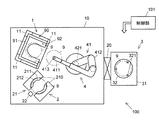
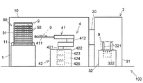
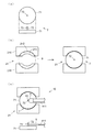
実施形態に係る基板処理装置100の全体構成について、図1、図2を参照しながら説明する。図1は、基板処理装置100の構成を模式的に示す平面図である。図2は、基板処理装置100の構成を模式的に示す側面図である。図2においては、説明の便宜上、基板処理装置100の一部の図示が省略されている。
<1. Configuration of Substrate Processing Apparatus 100>
The overall configuration of the substrate processing apparatus 100 according to the embodiment will be described with reference to FIGS. 1 and 2. FIG. 1 is a plan view schematically showing the configuration of the substrate processing apparatus 100. FIG. 2 is a side view schematically showing the configuration of the substrate processing apparatus 100. In FIG. 2, illustration of a part of the substrate processing apparatus 100 is omitted for convenience of explanation.

基板処理装置100は、複数枚の基板(例えば、略円形の半導体基板)9を多段に収納した基板収容部(一般に、マガジンラック、カセット等とも呼ばれる)90が載置される載置台1と、基板9の回転位置を補正するアライメント部2と、基板9に対して定められた処理を施す処理部3と、これら各部90,2,3の間で基板9を搬送する搬送ロボット4を備える。載置台1、アライメント部2、および、搬送ロボット4は、インデクサ部10に配置され、インデクサ部10と処理部3とは、ゲートバルブ20を介して接続される。基板処理装置100はさらに、これが備える各部を制御する制御部101を備える。   The substrate processing apparatus 100 includes a mounting table 1 on which a substrate accommodating portion (generally also referred to as a magazine rack, a cassette, etc.) 90 that stores a plurality of substrates (for example, substantially circular semiconductor substrates) 9 in multiple stages, An alignment unit 2 that corrects the rotational position of the substrate 9, a processing unit 3 that performs a predetermined process on the substrate 9, and a transfer robot 4 that transfers the substrate 9 between these units 90, 2, and 3 are provided. The mounting table 1, the alignment unit 2, and the transfer robot 4 are disposed in the indexer unit 10, and the indexer unit 10 and the processing unit 3 are connected via a gate valve 20. The substrate processing apparatus 100 further includes a control unit 101 that controls each unit included in the substrate processing apparatus 100.

<載置台1>
載置台1は、基板収容部90が載置される台である。基板収容部90は、複数枚の基板9を多段に収納する部材であり、背面壁および一対の側壁を備える筐体91と、その内部に等間隔で多段に設けられた複数の棚92とを備える。当該複数の棚92のそれぞれに、基板9が1枚ずつ載置される。各棚92はU字状の切り欠きが形成されており、これによって、棚92に対して搬送ロボット4が基板9を授受する際に棚92と搬送ロボット4のハンド411が干渉しないようになっている。
<Place 1>
The mounting table 1 is a table on which the substrate housing unit 90 is mounted. The substrate accommodating portion 90 is a member that accommodates a plurality of substrates 9 in multiple stages, and includes a housing 91 having a back wall and a pair of side walls, and a plurality of shelves 92 provided in multiple stages at equal intervals therein. Prepare. One substrate 9 is placed on each of the plurality of shelves 92. Each shelf 92 is formed with a U-shaped cutout, which prevents the shelf 92 and the hand 411 of the transfer robot 4 from interfering when the transfer robot 4 transfers the substrate 9 to the shelf 92. ing.

載置台1の上面には、基板収容部90の位置を規制するための複数の規制部材11が設けられている。各規制部材11は、具体的には例えば、平面視がL字状の部材であり、基板収容部90における背面壁と側壁との角部分に相当する位置、および(または)、当該側壁における正面の壁面と内側の壁面との角部分に相当する位置、に設けられる。この構成において、基板収容部90が、当該角部分が規制部材11のL字状の部分に沿うように配置されることによって、基板収容部90が適切な位置に配置されるようになっている。   A plurality of regulating members 11 for regulating the position of the substrate housing portion 90 are provided on the top surface of the mounting table 1. Specifically, each regulating member 11 is, for example, an L-shaped member in plan view, and a position corresponding to a corner portion between the back wall and the side wall in the substrate housing portion 90 and / or the front surface on the side wall. Is provided at a position corresponding to a corner portion between the inner wall surface and the inner wall surface. In this configuration, the substrate housing portion 90 is arranged at an appropriate position by arranging the corner portion along the L-shaped portion of the regulating member 11. .

<アライメント部2>
アライメント部2は、基板9を水平姿勢で保持する保持部21を備える。保持部21は、具体的には例えば、隙間をあけて対向配置された一対の保持具210を備える。各保持具210は、基板9の下面(具体的には、当該下面における周縁領域部分)に当接する水平な載置面211と、基板9の端面の一部分に当接する壁面212とを備える。壁面212は、上方から見て弧状に形成されており、その曲率半径は基板9の半径と略同一となっている。基板9は、上方から見て、中心が一対の保持具210の中心と一致するような位置において、一対の保持具210の各載置面211に水平姿勢で載置される。このとき、当該基板9は、一対の保持具210の各壁面212によって両側から位置規制された状態(すなわち、水平面内において位置ずれを起こさないように位置規制された状態)となる。この保持部21においては、一対の保持具210の間に隙間が存在するので、保持部21に対して搬送ロボット4が基板9を受け渡しする際に各保持具210とハンド411が干渉しないようになっている。
アライメント部2は、さらに、保持部21およびこれに保持された基板9をその中心を通る鉛直な回転軸の周りで回転させる回転駆動部(図示省略)と、当該回転される基板9の特徴部(具体的には例えば、基板9の周縁に形成されたノッチ、オリエンテーションフラット等)を検出する検出部22と、を備える。
<Alignment unit 2>
The alignment unit 2 includes a holding unit 21 that holds the substrate 9 in a horizontal posture. Specifically, the holding unit 21 includes, for example, a pair of holders 210 that are arranged to face each other with a gap. Each holder 210 includes a horizontal placement surface 211 that contacts the lower surface of the substrate 9 (specifically, a peripheral region portion on the lower surface) and a wall surface 212 that contacts a part of the end surface of the substrate 9. The wall surface 212 is formed in an arc shape when viewed from above, and its radius of curvature is substantially the same as the radius of the substrate 9. The substrate 9 is placed in a horizontal posture on each placement surface 211 of the pair of holders 210 at a position where the center coincides with the center of the pair of holders 210 when viewed from above. At this time, the substrate 9 is in a state in which the position of the substrate 9 is regulated from both sides by the wall surfaces 212 of the pair of holders 210 (that is, in a state of being regulated so as not to be displaced in the horizontal plane). In the holding unit 21, since there is a gap between the pair of holding tools 210, each holding tool 210 and the hand 411 do not interfere with each other when the transport robot 4 delivers the substrate 9 to the holding unit 21. It has become.
The alignment unit 2 further includes a rotation drive unit (not shown) that rotates the holding unit 21 and the substrate 9 held by the holding unit 21 around a vertical rotation axis that passes through the center of the holding unit 21, and a characteristic part of the rotated substrate 9. (Specifically, for example, a detection unit 22 that detects notches and orientation flats formed on the periphery of the substrate 9).

このアライメント部2にて基板9の回転位置を補正する場合、まず、搬送ロボット4が、ハンド411に保持された基板9を保持部21上に載置する。続いて、回転駆動部が、保持部21およびこれに保持されている基板9を1回転させる。基板9が1回転する間に、検出部22が、基板9の周縁に形成されている特徴部を検出する。特徴部が検出されると、回転駆動部が、当該特徴部が定められた方向に配置されるように、保持部21およびこれに保持されている基板9を回転させる。これによって、基板9の回転位置が補正される。   When correcting the rotation position of the substrate 9 by the alignment unit 2, first, the transfer robot 4 places the substrate 9 held by the hand 411 on the holding unit 21. Subsequently, the rotation driving unit rotates the holding unit 21 and the substrate 9 held by the holding unit 21 once. While the substrate 9 makes one rotation, the detection unit 22 detects a feature formed on the periphery of the substrate 9. When the feature portion is detected, the rotation driving portion rotates the holding portion 21 and the substrate 9 held by the rotation portion so that the feature portion is arranged in a predetermined direction. Thereby, the rotational position of the substrate 9 is corrected.

<処理部3>
処理部3は、基板9に定められた処理(この実施形態では、例えばプラズマ処理)を行う。処理部3は、処理チャンバー31と、その内部に配置された載置部32を備える。載置部32は、上方から見て円形の平板状の部材であり、その上面に、基板9が水平姿勢で載置される。載置部32には、その上面に対して出没可能に設けられた一群(図の例では、3個)のリフトピン321と、当該一群のリフトピン321を同期して出没させるリフトピン駆動機構322と、が設けられる。一群のリフトピン321は、載置部32に載置された基板9の下面の周縁領域と上方から見て重なる領域に、好ましくは等間隔で配列される。
処理部3は、さらに、処理チャンバー31内に各種の処理ガスを供給するガス供給部、処理チャンバー31内にプラズマを生成するためのプラズマ生成部、処理チャンバー31内の圧力を調整する排気部、等を備える(いずれも、図示省略)。
<Processing unit 3>
The processing unit 3 performs processing (for example, plasma processing in this embodiment) defined on the substrate 9. The processing unit 3 includes a processing chamber 31 and a placement unit 32 disposed therein. The placement portion 32 is a circular flat plate member as viewed from above, and the substrate 9 is placed in a horizontal posture on the upper surface thereof. The mounting portion 32 is provided with a group (three in the example of the figure) of lift pins 321 provided so as to be able to appear and retract with respect to the upper surface thereof, and a lift pin driving mechanism 322 for causing the group of lift pins 321 to appear and disappear in synchronization. Is provided. The group of lift pins 321 are preferably arranged at equal intervals in a region overlapping the peripheral region on the lower surface of the substrate 9 placed on the placement unit 32 when viewed from above.
The processing unit 3 further includes a gas supply unit that supplies various processing gases into the processing chamber 31, a plasma generation unit for generating plasma in the processing chamber 31, an exhaust unit that adjusts the pressure in the processing chamber 31, Etc. (both not shown).

この処理部3にて基板9に処理を施す場合、まず、搬送ロボット4が、ハンド411に保持された基板9を載置部32上に載置する。続いて、ゲートバルブ20が閉鎖されて処理チャンバー31が気密にされた上で、排気部が処理チャンバー31内を排気する。そして、ガス供給部が処理チャンバー31内に定められた処理ガスを供給するとともに、プラズマ生成部が処理チャンバー31内にプラズマを生成する。これによって、載置部32に載置された基板9に対するプラズマ処理(例えば、プラズマエッチング、プラズマアッシング、プラズマスパッタリング、プラズマ蒸着、プラズマCVD、等の処理)が行われる。もっとも、処理部3で行われる処理は必ずしもプラズマ処理である必要はなく、プラズマを用いない各種の処理(例えば、エッチング、アッシング、スパッタリング、蒸着、CVD、加熱、冷却、薬液塗布、洗浄等の処理)が行われてもよい。   When processing the substrate 9 by the processing unit 3, first, the transfer robot 4 places the substrate 9 held by the hand 411 on the placement unit 32. Subsequently, after the gate valve 20 is closed and the processing chamber 31 is hermetically sealed, the exhaust unit exhausts the inside of the processing chamber 31. The gas supply unit supplies the processing gas determined in the processing chamber 31, and the plasma generation unit generates plasma in the processing chamber 31. Thereby, plasma processing (for example, plasma etching, plasma ashing, plasma sputtering, plasma deposition, plasma CVD, or the like) is performed on the substrate 9 placed on the placement unit 32. However, the process performed in the processing unit 3 is not necessarily a plasma process, and various processes that do not use plasma (for example, processes such as etching, ashing, sputtering, vapor deposition, CVD, heating, cooling, chemical application, and cleaning) ) May be performed.

<搬送ロボット4>
搬送ロボット4は、ハンド411上に基板9を載置して、ハンド411を基板9の主面に平行な面(ここでは、水平面)の面内方向(ここでは、水平方向)と面外方向(ここでは、鉛直方向)に移動させて、基板9を目的とする位置まで搬送する装置であり、搬送アーム41と、これを駆動する駆動機構42とを備える。
<Transport robot 4>
The transfer robot 4 places the substrate 9 on the hand 411, and the hand 411 has an in-plane direction (here, horizontal direction) and an out-of-plane direction of a plane parallel to the main surface of the substrate 9 (here, horizontal plane). This is a device that moves the substrate 9 to a target position by moving in the vertical direction (here, a vertical direction), and includes a transfer arm 41 and a drive mechanism 42 that drives the transfer arm 41.

搬送アーム41は、1枚の基板9を支持する細長い板状のハンド411と、ハンド411と連結された多関節機構412と、を備える。ハンド411の上面であって、その上に基板9が載置されたときに基板9の下面の中央付近と対向する位置には、同心に配置された半径の異なる2個の円の円周に沿う溝から構成される吸引部413が形成されている。吸引部413は、バルブが介挿された真空ライン(図示省略)と接続されている。ハンド411の上に基板9が載置された状態でこのバルブが開放されると、真空ラインとハンド411の吸引部413が連通され、吸引部413が基板9を真空吸引し、基板9がハンド411上に固定的に保持(吸引保持)される。   The transfer arm 41 includes an elongated plate-like hand 411 that supports a single substrate 9, and a multi-joint mechanism 412 connected to the hand 411. On the upper surface of the hand 411, when the substrate 9 is placed on the upper surface of the hand 411, the position opposite to the vicinity of the center of the lower surface of the substrate 9 is the circumference of two circles having different radii arranged concentrically. A suction part 413 composed of a groove along the line is formed. The suction part 413 is connected to a vacuum line (not shown) in which a valve is inserted. When this valve is opened while the substrate 9 is placed on the hand 411, the vacuum line and the suction part 413 of the hand 411 communicate with each other, the suction part 413 sucks the substrate 9 in vacuum, and the substrate 9 takes the hand. 411 is fixedly held (suction-held).

駆動機構42は、搬送アーム41における多関節機構412の端部(ハンド411が接続された側と逆側の端部)と連結された軸部421を備える。この軸部421は鉛直に延在して、下端においてアームステージ422と連結されている。アームステージ422には、各種の駆動機構(具体的には、軸部421を回転させる回転駆動機構423、軸部421を伸縮させる昇降駆動機構424、および、多関節機構412を屈伸させる屈伸駆動機構425)が収容されている。回転駆動機構423が軸部421を回転させることによって、搬送アーム41が軸部421を中心に旋回する。昇降駆動機構424が軸部421を伸縮させることによって、搬送アーム41が昇降する。屈伸駆動機構425が多関節機構412を屈伸させることによって、搬送アーム41のハンド411が水平面内で搬送アーム41の旋回半径方向(すなわち、軸部421に対して近接あるいは離間する方向)に進退移動する。   The drive mechanism 42 includes a shaft portion 421 that is coupled to the end portion of the multi-joint mechanism 412 in the transport arm 41 (the end portion opposite to the side to which the hand 411 is connected). The shaft portion 421 extends vertically and is connected to the arm stage 422 at the lower end. The arm stage 422 includes various drive mechanisms (specifically, a rotary drive mechanism 423 that rotates the shaft portion 421, an elevating drive mechanism 424 that expands and contracts the shaft portion 421, and a flexure and extension drive mechanism that flexes and stretches the multi-joint mechanism 412. 425) is housed. When the rotation driving mechanism 423 rotates the shaft portion 421, the transport arm 41 turns around the shaft portion 421. The lifting / lowering driving mechanism 424 extends and contracts the shaft portion 421, so that the transport arm 41 moves up and down. The bending / extension driving mechanism 425 bends and stretches the multi-joint mechanism 412 so that the hand 411 of the transfer arm 41 moves forward and backward in the turning radius direction of the transfer arm 41 in the horizontal plane (that is, the direction close to or away from the shaft portion 421). To do.

上記の構成によって、搬送ロボット4は、ハンド411を、水平面内で旋回させることができ、当該旋回半径方向に沿った進退移動をさせることができ、さらに、昇降移動させることができる。つまり、ハンド411を、基板9の主面に平行な面の面内方向と面外方向に移動させることができる。   With the above-described configuration, the transfer robot 4 can turn the hand 411 in a horizontal plane, move forward and backward along the turning radius direction, and can further move up and down. That is, the hand 411 can be moved in the in-plane direction and the out-of-plane direction of the plane parallel to the main surface of the substrate 9.

搬送ロボット4は、制御部101の制御下でハンド411を移動させて、これを各載置台1に載置された基板収容部90、アライメント部2、および、処理部3の各々にアクセスさせて、当該各部90,2,3の間で基板9を搬送する。   The transfer robot 4 moves the hand 411 under the control of the control unit 101 to access each of the substrate storage unit 90, the alignment unit 2, and the processing unit 3 mounted on each mounting table 1. Then, the substrate 9 is transported between the parts 90, 2, 3.

<2.ティーチング装置10>
次に、搬送ロボット4に、基板9を搬送するべき位置のティーチングを行うティーチング装置10について説明する。ティーチング装置10は、ハンド411に直接的にあるいは間接的に設けられた特徴形状部分53と、基板9の搬送先に配置される治具6,7,8とを備える。
<2. Teaching device 10>
Next, the teaching apparatus 10 that performs teaching on the position where the substrate 9 should be transferred to the transfer robot 4 will be described. The teaching device 10 includes a characteristic shape portion 53 provided directly or indirectly on the hand 411 and jigs 6, 7, and 8 disposed at the transfer destination of the substrate 9.

<2−1.特徴形状部分53>
<i.特徴形状部分53をハンド411に間接的に設ける態様>
特徴形状部分53は、例えば、ハンド411に脱着自在に取り付けられる治具(以下、「ハンド側治具」ともいう)5に形成される。この場合、ハンド411にハンド側治具5が取り付けられることによって、ハンド411に特徴形状部分53が間接的に設けられることになる。
<2-1. Characteristic shape portion 53>
<I. Mode in which the characteristic shape portion 53 is indirectly provided on the hand 411>
The characteristic shape portion 53 is formed on, for example, a jig 5 (hereinafter also referred to as “hand side jig”) that is detachably attached to the hand 411. In this case, by attaching the hand side jig 5 to the hand 411, the characteristic shape portion 53 is indirectly provided on the hand 411.

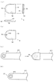
ハンド側治具5について、図3を参照しながら説明する。図3(a)は、ハンド側治具5の上面図および側面図である。図3(b)は、別の形態に係るハンド側治具5の上面図である。図3(c)は、ハンド側治具5がハンド411に取り付けられた状態を示す図である。   The hand side jig | tool 5 is demonstrated referring FIG. FIG. 3A is a top view and a side view of the hand side jig 5. FIG.3 (b) is a top view of the hand side jig | tool 5 which concerns on another form. FIG. 3C is a diagram showing a state where the hand side jig 5 is attached to the hand 411.

ハンド側治具5は、ハンド411の先端部分に対して着脱自在に構成されており、ティーチングを行う際にはハンド411の先端部分に取り付けられて用いられる。具体的には、ハンド側治具5は、上方から見てハンド411の先端よりも一回り大きな形状の板状部材51を備え、ハンド411の先端部分に、上側から板状部材51を被せることによって、ハンド側治具5がハンド411に取り付けられる。板状部材51の裏面には、これがハンド411に被せられたときにハンド411の先端部分の側面に沿うような周壁部52が形成されており、この周壁部52がハンド411の先端部分の側面に当接することによって、ハンド側治具5とハンド411とが互いに位置ずれを起こさないように位置規制される。   The hand side jig 5 is configured to be detachable with respect to the distal end portion of the hand 411, and is used by being attached to the distal end portion of the hand 411 when performing teaching. Specifically, the hand-side jig 5 includes a plate-like member 51 that is slightly larger than the tip of the hand 411 when viewed from above, and the tip of the hand 411 is covered with the plate-like member 51 from above. Thus, the hand side jig 5 is attached to the hand 411. A peripheral wall portion 52 is formed on the back surface of the plate-like member 51 so as to be along the side surface of the tip portion of the hand 411 when the plate member 51 is put on the hand 411, and the peripheral wall portion 52 is a side surface of the tip portion of the hand 411. , The position of the hand side jig 5 and the hand 411 is regulated so as not to be displaced from each other.

板状部材51には、図3(b)に示されるように、周壁部52とハンド411とが当接し合う部分に窓部510を設けてもよい。この構成によると、窓部510から、周壁部52とハンド411との位置関係を確認することができる。すなわち、窓部510内を視認して、周壁部52とハンド411とが当接し合っていることが確認できれば、ハンド側治具5が適切にハンド411に取り付けられていると判断することができる。   As shown in FIG. 3B, the plate-like member 51 may be provided with a window portion 510 at a portion where the peripheral wall portion 52 and the hand 411 come into contact with each other. According to this configuration, the positional relationship between the peripheral wall portion 52 and the hand 411 can be confirmed from the window portion 510. That is, when the inside of the window 510 is visually confirmed and it can be confirmed that the peripheral wall 52 and the hand 411 are in contact with each other, it can be determined that the hand side jig 5 is appropriately attached to the hand 411. .

ハンド側治具5の表面には、特徴形状部分53が形成される。この特徴形状部分53は、基板9(ハンド411に保持された状態の基板9)の主面と平行な断面が円弧状の形状部分であり、具体的には、円弧状に切り欠かれた凹部である。この円弧は、中心角が90°以上かつ180°以下の円弧状であることが好ましく、特に、中心角が180°の円弧(つまりは半円)であることが好ましい。また、この特徴形状部分53は、ハンド側治具5の側面であって、ハンド411の最先端部分と対応する位置に形成されることが好ましい。   A characteristic shape portion 53 is formed on the surface of the hand side jig 5. The characteristic shape portion 53 is a circular arc-shaped cross section parallel to the main surface of the substrate 9 (the substrate 9 held by the hand 411), and specifically, a concave portion cut out in an arc shape. It is. This arc is preferably an arc having a central angle of 90 ° or more and 180 ° or less, and particularly preferably an arc having a center angle of 180 ° (that is, a semicircle). Further, the characteristic shape portion 53 is preferably formed on the side surface of the hand side jig 5 and at a position corresponding to the most distal portion of the hand 411.

<ii.特徴形状部分53をハンド411に直接的に設ける態様>
特徴形状部分53は、ハンド411に直接に形成されていてもよい。
この場合も、ハンド側治具5に特徴形状部分53を形成する場合と同様、特徴形状部分53は、基板9(ハンド411に保持された状態の基板9)の主面と平行な断面が円弧状の形状部分であり、具体的には、円弧状に切り欠かれた凹部とすることができる。例えば、図3(d)に示されるように、ハンド411の側面であって、ハンド411の最先端部分に、円弧状に切り欠かれた凹部を形成することによって、特徴形状部分53を形成することができる。
<Ii. Mode in which the characteristic shape portion 53 is provided directly on the hand 411>
The characteristic shape portion 53 may be formed directly on the hand 411.
Also in this case, as in the case where the characteristic shape portion 53 is formed in the hand side jig 5, the characteristic shape portion 53 has a circular cross section parallel to the main surface of the substrate 9 (the substrate 9 held by the hand 411). It is an arc-shaped part, and can be specifically a recess cut out in an arc shape. For example, as shown in FIG. 3 (d), the characteristic shape portion 53 is formed by forming a concave portion cut out in an arc shape on the side surface of the hand 411 and at the most distal portion of the hand 411. be able to.

<2−2.治具6,7,8>
次に、特徴形状部分53と対にして用いられる治具6,7,8について説明する。当該治具6,7,8は、基板9の搬送先(すなわち、ティーチングするべき位置)に応じたものとなっている。
以下においては、載置部1に載置された収容部90の各棚92上に基板9を搬送するときの搬送位置のティーチングに用いられる治具(以下「載置台用治具」ともいう)6、アライメント部2の保持部21上に基板9を搬送するときの搬送位置のティーチングに用いられる治具(以下「アライメント部用治具」ともいう)7、および、処理部3の載置部32上に基板9を搬送するときの搬送位置のティーチングに用いられる治具(以下「処理部用治具」ともいう)8、のそれぞれについて、説明する。
<2-2. Jig 6, 7, 8>
Next, the jigs 6, 7, and 8 used as a pair with the characteristic shape portion 53 will be described. The jigs 6, 7, and 8 correspond to the transfer destination of the substrate 9 (that is, the position to be taught).
In the following, a jig used for teaching the transfer position when the substrate 9 is transferred onto each shelf 92 of the storage unit 90 mounted on the mounting unit 1 (hereinafter also referred to as “mounting table jig”). 6. Jig (hereinafter also referred to as “alignment unit jig”) 7 used for teaching the transfer position when the substrate 9 is transferred onto the holding unit 21 of the alignment unit 2, and the placement unit of the processing unit 3 Each of jigs 8 (hereinafter also referred to as “processing unit jigs”) 8 used for teaching the transfer position when the substrate 9 is transferred onto the substrate 32 will be described.

<2−2−1.載置台用治具6>
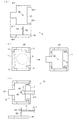
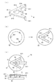
載置台用治具6について、図4を参照しながら説明する。図4(a)は、載置台用治具6の上面図および側面図である。図4(b)は、載置台用治具6が載置台1上に載置された状態を示す図である。図4(c)は、載置台用治具6を用いたティーチングの態様を説明するための図である。
<2-2-1. Mounting jig 6>
The mounting table jig 6 will be described with reference to FIG. FIG. 4A is a top view and a side view of the mounting table jig 6. FIG. 4B is a diagram showing a state where the mounting table jig 6 is mounted on the mounting table 1. FIG. 4C is a view for explaining a teaching mode using the mounting table jig 6.

<a.構成>
載置台用治具6は、ベース部61と、これに立設されたガイドポール62と、ガイドポール62の長手方向内の所定位置に形成されたガイドポイント63と、を備える。
<A. Configuration>
The mounting table jig 6 includes a base portion 61, a guide pole 62 erected on the base portion 61, and guide points 63 formed at predetermined positions in the longitudinal direction of the guide pole 62.

ベース部61は、上方から見て基板収容部90とほぼ同じサイズの板状部材である。ティーチングの際には、このベース部61が、載置台1における基板収容部90が載置される位置に載置される。ベース部61は、好ましくは、載置台1上に設けられている各規制部材11のL字状部分に沿うような形状部分611を備える。これによって、ベース部61を、載置台1上における基板収容部90が載置される位置に正確に載置することが可能となる。   The base portion 61 is a plate-like member having substantially the same size as the substrate housing portion 90 when viewed from above. At the time of teaching, the base portion 61 is placed at a position where the substrate accommodating portion 90 is placed on the placement table 1. The base portion 61 preferably includes a shape portion 611 that follows the L-shaped portion of each regulating member 11 provided on the mounting table 1. This makes it possible to accurately place the base portion 61 at a position on the placement table 1 where the substrate accommodating portion 90 is placed.

ガイドポール62は、柱状部材であり、ベース部61の表面の法線方向に延在して、下端がベース部61に固定される。ガイドポール62は、ベース部61が載置台1上に載置されたときに、当該載置台1上に正しく載置された基板収容部90の各棚92に正しく載置された基板9の中心を通る鉛直軸と重なるような位置に形成される。
ガイドポール62は、当該基板9の主面と平行な断面の形状(すなわち、長手方向と直交する方向で切断した断面の形状)が一定であり、当該断面形状は、特徴形状部分53と対応する形状となっている。上述したとおり、この実施の形態では、特徴形状部分53は円弧状に切り欠かれた凹部であるところ、ガイドポール62は断面が円形の棒により形成され、当該円の半径が特徴形状部分53の円弧の曲率半径と一致するようなものとなっている。
The guide pole 62 is a columnar member, extends in the normal direction of the surface of the base portion 61, and has a lower end fixed to the base portion 61. The guide pole 62 is the center of the substrate 9 that is correctly placed on each shelf 92 of the substrate housing portion 90 that is correctly placed on the placement table 1 when the base portion 61 is placed on the placement table 1. It is formed at a position that overlaps the vertical axis that passes through.
The guide pole 62 has a constant cross-sectional shape parallel to the main surface of the substrate 9 (that is, a cross-sectional shape cut in a direction perpendicular to the longitudinal direction), and the cross-sectional shape corresponds to the characteristic shape portion 53. It has a shape. As described above, in this embodiment, the characteristic shape portion 53 is a concave portion cut out in an arc shape. However, the guide pole 62 is formed by a rod having a circular cross section, and the radius of the circle is the characteristic shape portion 53. It is the same as the radius of curvature of the arc.

ガイドポイント63は、ガイドポール62の長手方向内の所定の位置を示すものであり、具体的には例えば、ガイドポール62の長手方向と直交する方向に延在するけがき線により形成される。ガイドポイント63は、ベース部61が載置台1上に載置されたときに、当該載置台1上に正しく載置された基板収容部90の各棚92のうちから選択された1個の棚92(例えば、上下方向において真ん中の棚92であり、以下「対象棚92」ともいう)に正しく載置された基板9の表面を通る水平面と重なるような位置に形成される。   The guide point 63 indicates a predetermined position in the longitudinal direction of the guide pole 62. Specifically, for example, the guide point 63 is formed by a marking line extending in a direction orthogonal to the longitudinal direction of the guide pole 62. The guide point 63 is one shelf selected from among the shelves 92 of the substrate storage unit 90 that is correctly placed on the placement table 1 when the base portion 61 is placed on the placement table 1. 92 (for example, the shelf 92 in the middle in the vertical direction, hereinafter also referred to as the “target shelf 92”) is formed at a position that overlaps the horizontal plane passing through the surface of the substrate 9 that is correctly placed.

<b.ティーチングの態様>
載置台用治具6を用いてティーチングを行う態様について説明する。この場合のティーチングポイントは、載置部1に正しく載置された収容部90における対象棚92上に正しく載置された基板9の位置である。当該ティーチングポイントが特定されることによって、対象棚92に基板9を正しい位置で受け渡すことができるようなハンド411の位置が特定される。つまり、対象棚92に対する基板9の受け渡し位置がティーチングされる。
<B. Teaching mode>
A mode in which teaching is performed using the mounting table jig 6 will be described. The teaching point in this case is the position of the substrate 9 that is correctly placed on the target shelf 92 in the storage portion 90 that is correctly placed on the placement portion 1. By specifying the teaching point, the position of the hand 411 that can deliver the substrate 9 to the target shelf 92 at the correct position is specified. That is, the delivery position of the substrate 9 with respect to the target shelf 92 is taught.

まず、載置台用治具6のベース部61を、載置台1上における基板収容部90が載置される位置に載置する。上述したとおり、このとき、ガイドポール62が、載置部1に載置された収容部90の対象棚92に載置される基板9の中心を通る鉛直軸と重なるような位置に配置され、ガイドポイント63が、当該基板9の表面を通る水平面と重なるような位置に配置される。つまり、ガイドポイント63が、ティーチングポイントと重なる位置に配置される。   First, the base portion 61 of the mounting table jig 6 is mounted on the mounting table 1 at a position where the substrate housing unit 90 is mounted. As described above, at this time, the guide pole 62 is disposed at a position that overlaps the vertical axis passing through the center of the substrate 9 placed on the target shelf 92 of the storage unit 90 placed on the placement unit 1, The guide points 63 are arranged at positions that overlap with a horizontal plane passing through the surface of the substrate 9. That is, the guide point 63 is disposed at a position overlapping the teaching point.

続いて、ハンド側治具5が取り付けられることによって特徴形状部分53が間接的に形成されたハンド411(図3(c))、あるいは、特徴形状部分53が直接的に形成されているハンド411(図3(d))を、水平面内において移動させて、特徴形状部分53とガイドポール62とが接触した状態(具体的には、噛み合った状態)として、水平面内においてハンド411とガイドポール62の位置関係を固定する(図4(c)の上面図)。これにより、ハンド411の水平面内における位置が決定される。さらに、当該噛み合った状態のままでハンド411を昇降させて(すなわち、ガイドポール62に沿ってスライドさせて)、ハンド411あるいはハンド側治具5の例えば上面がガイドポイント63に配置された状態とする(図4(c)の側面図)。これにより、ハンド411の鉛直方向の位置が決定され、水平面内と鉛直方向の両方において(すなわち、3次元位置において)、ハンド411がティーチングポイントに位置合わせされた状態となる。   Subsequently, the hand 411 in which the characteristic shape portion 53 is indirectly formed by attaching the hand side jig 5 (FIG. 3C), or the hand 411 in which the characteristic shape portion 53 is directly formed. (FIG. 3D) is moved in the horizontal plane so that the characteristic shape portion 53 and the guide pole 62 are in contact with each other (specifically, in a meshed state), the hand 411 and the guide pole 62 in the horizontal plane. Is fixed (a top view of FIG. 4C). Thereby, the position of the hand 411 in the horizontal plane is determined. Further, the hand 411 is moved up and down (that is, slid along the guide pole 62) in the engaged state, and the upper surface of the hand 411 or the hand side jig 5 is disposed at the guide point 63, for example. (Side view of FIG. 4C). Thereby, the vertical position of the hand 411 is determined, and the hand 411 is aligned with the teaching point both in the horizontal plane and in the vertical direction (that is, in the three-dimensional position).

ハンド411がティーチングポイントに位置合わせされると、このときのハンド411の位置を制御部101の記憶装置に記憶する。これによって、ティーチングポイントが特定され、当該特定されたティーチングポイントに基づいて、対象棚92に対する基板9の受け渡し位置がティーチングされる。ここではさらに、当該ティーチングされた受け渡し位置に基づいて、他の全ての棚92に対する基板9の受け渡し位置が計算により算出されて記憶される。   When the hand 411 is aligned with the teaching point, the position of the hand 411 at this time is stored in the storage device of the control unit 101. Thereby, the teaching point is specified, and the delivery position of the substrate 9 with respect to the target shelf 92 is taught based on the specified teaching point. Here, based on the taught delivery position, the delivery positions of the substrates 9 with respect to all other shelves 92 are calculated and stored.

<2−2−2.アライメント部用治具7>
アライメント部用治具7について、図5を参照しながら説明する。図5(a)は、アライメント部用治具7の上面図および側面図である。図5(b)は、アライメント部用治具7が保持部21上に載置された状態を示す図である。図5(c)は、アライメント部用治具7を用いたティーチングの態様を説明するための図である。
<2-2-2. Alignment Jig 7>
The alignment portion jig 7 will be described with reference to FIG. FIG. 5A is a top view and a side view of the alignment portion jig 7. FIG. 5B is a diagram illustrating a state where the alignment unit jig 7 is placed on the holding unit 21. FIG. 5C is a diagram for explaining a teaching mode using the alignment portion jig 7.

<a.構成>
アライメント部用治具7は、ベース部71と、これに立設されたガイドポール72と、ガイドポール72の長手方向内の所定位置に形成されたガイドポイント73と、を備える。
<A. Configuration>
The alignment portion jig 7 includes a base portion 71, a guide pole 72 erected on the base portion 71, and guide points 73 formed at predetermined positions in the longitudinal direction of the guide pole 72.

ベース部71は、上方から見て基板9とほぼ同じサイズの板状部材である。ティーチングの際には、このベース部71が、アライメント部2の保持部21上に載置される。具体的には、ベース部71は、上方から見て、中心が一対の保持具210の中心と一致するような位置において、一対の保持具210の各載置面211上に水平姿勢で載置される。ベース部71は上方から見て基板9とほぼ同じサイズであるので、このときに、ベース部71は、一対の保持具210の各壁面212によって両側から位置規制された状態(すなわち、水平面内において位置ずれを起こさないように位置規制された状態)となる。   The base portion 71 is a plate-like member having substantially the same size as the substrate 9 when viewed from above. In teaching, the base portion 71 is placed on the holding portion 21 of the alignment portion 2. Specifically, the base portion 71 is placed in a horizontal posture on each placement surface 211 of the pair of holders 210 at a position where the center coincides with the center of the pair of holders 210 when viewed from above. Is done. Since the base portion 71 is substantially the same size as the substrate 9 when viewed from above, at this time, the base portion 71 is positioned from both sides by the respective wall surfaces 212 of the pair of holders 210 (that is, in a horizontal plane). The position is regulated so as not to cause a displacement.

ガイドポール72は、柱状部材であり、ベース部71の表面の法線方向に延在して、下端がベース部71に固定される。ガイドポール72は、ベース部71が保持部21上に載置されたときに、保持部21に正しく保持された基板9の中心を通る鉛直軸と重なるような位置に、形成される。
ガイドポール72は、当該基板9の主面と平行な断面の形状(すなわち、長手方向と直交する方向で切断した断面の形状)が一定であり、当該断面形状は、特徴形状部分53と対応する形状となっている。上述したとおり、この実施の形態では、特徴形状部分53は円弧状に切り欠かれた凹部であるところ、ガイドポール72は断面が円形の棒により形成され、当該円の半径が特徴形状部分53の円弧の曲率半径と一致するようなものとなっている。
The guide pole 72 is a columnar member, extends in the normal direction of the surface of the base portion 71, and has a lower end fixed to the base portion 71. The guide pole 72 is formed at a position that overlaps the vertical axis passing through the center of the substrate 9 correctly held by the holding unit 21 when the base unit 71 is placed on the holding unit 21.
The guide pole 72 has a constant cross-sectional shape parallel to the main surface of the substrate 9 (that is, a cross-sectional shape cut in a direction orthogonal to the longitudinal direction), and the cross-sectional shape corresponds to the characteristic shape portion 53. It has a shape. As described above, in this embodiment, the characteristic shape portion 53 is a concave portion cut out in an arc shape. However, the guide pole 72 is formed by a rod having a circular cross section, and the radius of the circle is the characteristic shape portion 53. It is the same as the radius of curvature of the arc.

ガイドポイント73は、ガイドポール72の長手方向内の所定の位置を示すものであり、具体的には例えば、ガイドポール72の長手方向と直交する方向に延在するけがき線により形成される。ガイドポイント73は、ベース部71が保持部21上に載置されたときに、保持部21に正しく保持される基板9の表面を通る水平面と平行な面であって、当該水平面との離間距離が既知である面(対象面)と重なるような位置に形成される。   The guide point 73 indicates a predetermined position in the longitudinal direction of the guide pole 72, and is specifically formed by a marking line extending in a direction orthogonal to the longitudinal direction of the guide pole 72, for example. The guide point 73 is a plane parallel to a horizontal plane passing through the surface of the substrate 9 correctly held by the holding unit 21 when the base unit 71 is placed on the holding unit 21, and is separated from the horizontal plane. Is formed at a position overlapping with a known surface (target surface).

<b.ティーチングの態様>
アライメント部用治具7を用いてティーチングを行う態様について説明する。この場合のティーチングポイントは、保持部21に正しく保持された基板9の位置と既知の関係にある位置である。当該ティーチングポイントが特定されることによって、保持部21に基板9を正しい位置で受け渡すことができるようなハンド411の位置が特定される。つまり、保持部21に対する基板9の受け渡し位置がティーチングされる。
<B. Teaching mode>
A mode in which teaching is performed using the alignment unit jig 7 will be described. The teaching point in this case is a position having a known relationship with the position of the substrate 9 correctly held by the holding unit 21. By specifying the teaching point, the position of the hand 411 that can deliver the substrate 9 to the holding unit 21 at the correct position is specified. That is, the delivery position of the substrate 9 with respect to the holding unit 21 is taught.

まず、アライメント部用治具7のベース部71を、保持部21上に載置する(図5(b))。上述したとおり、このとき、ガイドポール72が、保持部21に保持される基板9の中心を通る鉛直軸と重なるような位置に配置され、ガイドポイント73が、当該基板9の表面を通る水平面と既知の位置関係にある対象面と重なるような位置に配置される。つまり、ガイドポイント73が、ティーチングポイントと重なる位置に配置される。   First, the base portion 71 of the alignment portion jig 7 is placed on the holding portion 21 (FIG. 5B). As described above, at this time, the guide pole 72 is disposed at a position overlapping the vertical axis passing through the center of the substrate 9 held by the holding unit 21, and the guide point 73 is a horizontal plane passing through the surface of the substrate 9. It is arranged at a position that overlaps the target surface in a known positional relationship. That is, the guide point 73 is disposed at a position overlapping the teaching point.

続いて、ハンド側治具5が取り付けられることによって特徴形状部分53が間接的に形成されたハンド411(図3(c))、あるいは、特徴形状部分53が直接的に形成されているハンド411(図3(d))を、水平面内において移動させて、特徴形状部分53とガイドポール72とが噛み合った状態として、水平面内においてハンド411とガイドポール72の位置関係を固定する(図5(c)の上面図)。これにより、ハンド411の水平面内における位置が決定される。さらに、当該噛み合った状態のままでハンド411を昇降させて(すなわち、ガイドポール72に沿ってスライドさせて)、ハンド411あるいはハンド側治具5の例えば上面がガイドポイント73に配置された状態とする(図5(c)の側面図)。これにより、ハンド411の鉛直方向の位置が決定され、水平面内と鉛直方向の両方において(すなわち、3次元位置において)、ハンド411がティーチングポイントに位置合わせされた状態となる。   Subsequently, the hand 411 in which the characteristic shape portion 53 is indirectly formed by attaching the hand side jig 5 (FIG. 3C), or the hand 411 in which the characteristic shape portion 53 is directly formed. (FIG. 3D) is moved in the horizontal plane, and the positional relationship between the hand 411 and the guide pole 72 is fixed in the horizontal plane in a state where the characteristic shape portion 53 and the guide pole 72 are engaged with each other (FIG. 5 ( c) Top view). Thereby, the position of the hand 411 in the horizontal plane is determined. Further, the hand 411 is moved up and down (that is, slid along the guide pole 72) in the engaged state, and the upper surface of the hand 411 or the hand side jig 5 is arranged at the guide point 73. (Side view of FIG. 5C). Thereby, the vertical position of the hand 411 is determined, and the hand 411 is aligned with the teaching point both in the horizontal plane and in the vertical direction (that is, in the three-dimensional position).

ハンド411がティーチングポイントに位置合わせされると、このときのハンド411の位置を制御部101の記憶装置に記憶する。これによって、ティーチングポイントが特定され、当該特定されたティーチングポイントに基づいて、保持部21に対する基板9の受け渡し位置がティーチングされる。   When the hand 411 is aligned with the teaching point, the position of the hand 411 at this time is stored in the storage device of the control unit 101. Thereby, the teaching point is specified, and the delivery position of the substrate 9 to the holding unit 21 is taught based on the specified teaching point.

<2−2−3.処理部用治具8>
処理部用治具8について、図6を参照しながら説明する。図6(a)は、処理部用治具8の斜視図である。図6(b)は、処理部用治具8が載置部32上に載置された状態を示す図である。図6(c)は、処理部用治具8を用いたティーチングの態様を説明するための図である。
<2-2-3. Processing Unit Jig 8>
The processing unit jig 8 will be described with reference to FIG. FIG. 6A is a perspective view of the processing unit jig 8. FIG. 6B is a diagram showing a state in which the processing unit jig 8 is placed on the placement unit 32. FIG. 6C is a diagram for explaining a teaching mode using the processing unit jig 8.

<a.構成>
処理部用治具8は、ベース部81と、これに立設されたガイドポール82と、ガイドポール82の長手方向内の所定位置に形成されたガイドポイント83と、を備える。
<A. Configuration>
The processing portion jig 8 includes a base portion 81, a guide pole 82 erected on the base portion 81, and guide points 83 formed at predetermined positions in the longitudinal direction of the guide pole 82.

ベース部81は、複数のリフトピン収容部811と、これらを連結して一体的に支持する薄板状の支持部812と、を備える。各リフトピン収容部811は、上端が支持材812と連結された筒状の部材であり、載置部32が備える一群のリフトピン321のそれぞれと対応する位置に配置されている。具体的には、この実施形態においては、各リフトピン321は三角形の頂点に相当する位置に配置されており、これに対応して、各リフトピン収容部811も三角形の頂点に相当する位置に配置される。すなわち、支持部812は、当該三角形の2つの辺に沿うような屈曲した形状部分813を備え、その両端点および屈曲部分に、リフトピン収容部811が連結される。また、支持部812は、当該形状部分813の各端点と屈曲部分との中間位置を連結する連結部分814を備え、ここに、後述するガイドポール82が固定される。
ベース部81が載置部32上に載置された状態において、各リフトピン収容部811が各リフトピン321に上側から被さり、各リフトピン321の先端部分が各リフトピン収容部811の筒内部に収容された状態となる。これによって、ベース部81は、水平面内において位置ずれを起こさないように位置規制された状態となる。
The base portion 81 includes a plurality of lift pin accommodating portions 811 and a thin plate-like support portion 812 that connects and integrally supports them. Each lift pin accommodating portion 811 is a cylindrical member whose upper end is connected to the support member 812, and is disposed at a position corresponding to each of the group of lift pins 321 included in the placement portion 32. Specifically, in this embodiment, each lift pin 321 is disposed at a position corresponding to the apex of the triangle, and correspondingly, each lift pin accommodating portion 811 is also disposed at a position corresponding to the apex of the triangle. The That is, the support portion 812 includes a bent shape portion 813 that extends along two sides of the triangle, and the lift pin accommodating portion 811 is coupled to both end points and the bent portion. The support portion 812 includes a connecting portion 814 that connects intermediate positions between the end points of the shape portion 813 and the bent portion, and a guide pole 82 to be described later is fixed thereto.
In a state where the base portion 81 is placed on the placement portion 32, each lift pin accommodating portion 811 covers each lift pin 321 from the upper side, and the tip portion of each lift pin 321 is accommodated inside the cylinder of each lift pin accommodating portion 811. It becomes a state. As a result, the base portion 81 is in a state in which the position is regulated so as not to cause a positional shift in the horizontal plane.

ガイドポール82は、柱状部材であり、側面において支持部材812の連結部分814の側面に固定されて、支持部材812の表面の法線方向に延在するように配置される。ガイドポール82は、ベース部81が載置部32上に載置されたときに、載置部32に正しく載置された基板9の中心を通る鉛直軸と重なるような位置に、形成される。
ガイドポール82は、当該基板9の主面と平行な断面の形状(すなわち、長手方向と直交する方向で切断した断面の形状)が一定であり、当該断面形状は、特徴形状部分53と対応する形状となっている。上述したとおり、この実施の形態では、特徴形状部分53は円弧状に切り欠かれた凹部であるところ、ガイドポール82は、円弧状に膨らんだ凸状断面を有する棒状部材(具体的には、断面が半長円(すなわち、長円(二つの等しい長さの平行線と二つの半円形からなる図形)を、その平行線と直交する分割線に沿って半分に分割した形状)の棒状部材)により形成され、当該円弧状の部分の曲率半径が、特徴形状部分53の円弧の曲率半径と一致するようなものとなっている。
The guide pole 82 is a columnar member, is fixed to the side surface of the connecting portion 814 of the support member 812 on the side surface, and is arranged to extend in the normal direction of the surface of the support member 812. The guide pole 82 is formed at a position that overlaps the vertical axis passing through the center of the substrate 9 that is correctly placed on the placement portion 32 when the base portion 81 is placed on the placement portion 32. .
The guide pole 82 has a constant cross-sectional shape parallel to the main surface of the substrate 9 (that is, a cross-sectional shape cut in a direction perpendicular to the longitudinal direction), and the cross-sectional shape corresponds to the characteristic shape portion 53. It has a shape. As described above, in this embodiment, the characteristic shape portion 53 is a concave portion cut out in an arc shape, and the guide pole 82 is a rod-like member having a convex cross section swelled in an arc shape (specifically, A rod-like member whose cross section is a semi-oval (ie, a shape obtained by dividing an oval (a figure composed of two equal-length parallel lines and two semi-circles) in half along a dividing line perpendicular to the parallel lines) ), And the radius of curvature of the arc-shaped portion matches the radius of curvature of the arc of the feature-shaped portion 53.

ガイドポイント83は、ガイドポール82の長手方向内の所定の位置を示すものであり、具体的には例えば、ガイドポール82の長手方向と直交する方向に延在するけがき線により形成される。ガイドポイント83は、ベース部81が載置部32上に載置されたときに、載置部32上に正しく載置された基板9の表面を通る水平面(あるいは、当該水平面と平行であって、当該水平面との離間距離が既知である面であってもよい)と重なるような位置に形成される。   The guide point 83 indicates a predetermined position in the longitudinal direction of the guide pole 82. Specifically, for example, the guide point 83 is formed by a marking line extending in a direction orthogonal to the longitudinal direction of the guide pole 82. The guide point 83 is a horizontal plane (or parallel to the horizontal plane) that passes through the surface of the substrate 9 that is correctly placed on the placement portion 32 when the base portion 81 is placed on the placement portion 32. , Or a surface with a known separation distance from the horizontal plane).

<b.ティーチングの態様>
アライメント部用治具7を用いてティーチングを行うに態様について説明する。この場合のティーチングポイントは、載置部32に正しく載置された基板9の位置(あるいは、当該位置と既知の関係にある位置)である。当該ティーチングポイントが特定されることによって、載置部32に基板9を正しい位置で受け渡すことができるようなハンド411の位置が特定される。つまり、載置部32に対する基板9の受け渡し位置がティーチングされる。
<B. Teaching mode>
A mode for performing teaching using the alignment portion jig 7 will be described. The teaching point in this case is the position of the substrate 9 that is correctly placed on the placement portion 32 (or a position that has a known relationship with the position). By specifying the teaching point, the position of the hand 411 that can deliver the substrate 9 to the placement unit 32 at the correct position is specified. That is, the delivery position of the substrate 9 with respect to the placement unit 32 is taught.

まず、アライメント部用治具7のベース部材81を載置部32上に載置して、各リフトピン収容部811が各リフトピン321に上側から被さって各リフトピン321の先端部分が各リフトピン収容部811の筒内部に収容された状態とする(図6(b))。上述したとおり、このとき、ガイドポール82が、載置部32に載置される基板9の中心を通る鉛直軸に重なるような位置に配置され、ガイドポイント83が、当該基板9の表面を通る水平面と重なるような位置に配置される。つまり、ガイドポイント83が、ティーチングポイントと重なる位置に配置される。   First, the base member 81 of the alignment portion jig 7 is placed on the placement portion 32, each lift pin accommodating portion 811 covers each lift pin 321 from above, and the tip of each lift pin 321 is each lift pin accommodating portion 811. It is set as the state accommodated in the pipe | tube inside (FIG.6 (b)). As described above, at this time, the guide pole 82 is disposed at a position overlapping the vertical axis passing through the center of the substrate 9 placed on the placement portion 32, and the guide point 83 passes through the surface of the substrate 9. It is arranged at a position that overlaps the horizontal plane. That is, the guide point 83 is disposed at a position overlapping the teaching point.

続いて、ハンド側治具5が取り付けられることによって特徴形状部分53が間接的に形成されたハンド411(図3(c))、あるいは、特徴形状部分53が直接的に形成されているハンド411(図3(d))を、水平面内において移動させて、特徴形状部分53とガイドポール82とが噛み合った状態として、水平面内においてハンド411とガイドポール82の位置関係を固定する(図6(c)の上面図)。これにより、ハンド411の水平面内における位置が決定される。さらに、当該噛み合った状態のままでハンド411を昇降させて(すなわち、ガイドポール82に沿ってスライドさせて)、ハンド411あるいはハンド側治具5の例えば上面がガイドポイント83に配置された状態とする(図6(c)の側面図)。これにより、ハンド411の鉛直方向の位置が決定され、水平面内と鉛直方向の両方において(すなわち、3次元位置において)、ハンド411がティーチングポイントに位置合わせされた状態となる。   Subsequently, the hand 411 in which the characteristic shape portion 53 is indirectly formed by attaching the hand side jig 5 (FIG. 3C), or the hand 411 in which the characteristic shape portion 53 is directly formed. (FIG. 3D) is moved in the horizontal plane, and the positional relationship between the hand 411 and the guide pole 82 is fixed in the horizontal plane, assuming that the characteristic shape portion 53 and the guide pole 82 are engaged with each other (FIG. 6 ( c) Top view). Thereby, the position of the hand 411 in the horizontal plane is determined. Further, the hand 411 is moved up and down (that is, slid along the guide pole 82) in the engaged state, and the upper surface of the hand 411 or the hand side jig 5 is disposed at the guide point 83, for example. (Side view of FIG. 6C). Thereby, the vertical position of the hand 411 is determined, and the hand 411 is aligned with the teaching point both in the horizontal plane and in the vertical direction (that is, in the three-dimensional position).

ハンド411がティーチングポイントに位置合わせされると、このときのハンド411の位置を制御部101の記憶装置に記憶する。これによって、ティーチングポイントが特定され、当該特定されたティーチングポイントに基づいて、載置部32に対する基板9の受け渡し位置がティーチングされる。   When the hand 411 is aligned with the teaching point, the position of the hand 411 at this time is stored in the storage device of the control unit 101. As a result, the teaching point is specified, and the delivery position of the substrate 9 with respect to the placement unit 32 is taught based on the specified teaching point.

<3.変形例>
上記に例示したティーチング装置10は、特徴形状部分53が円弧状に切り欠かれた凹部であり、これと対になって用いられる各治具6,7,8が円弧状に膨らんだ凸状断面を有するものとしたが、各部の形状の組み合わせはこれに限らない。例えば、特徴形状部分53が、円弧状に膨らんだ凸部であり、これと対になって用いられる各治具6,7,8が当該円弧の曲率半径と一致するような曲率半径の円弧状に凹んだ凹状断面を有するものであってもよい。
<3. Modification>
The teaching device 10 exemplified above is a concave portion in which the characteristic shape portion 53 is cut out in an arc shape, and each of the jigs 6, 7, 8 used in a pair with the convex shape cross section is expanded in an arc shape. However, the combination of the shapes of the respective parts is not limited to this. For example, the characteristic shape portion 53 is a convex portion that swells in an arc shape, and an arc shape having a curvature radius such that the jigs 6, 7, and 8 used as a pair match the curvature radius of the arc shape. It may have a concave cross section that is recessed.

上記に例示した各治具6,7,8において、ガイドポイント63,73,83は、ガイドポール部61,71,81の延在途中に形成されたけがき線により構成されていたが、ガイドポイントの構成例はそれに限らない。例えば、ガイドポール部61,71,81の上端位置が、ガイドポイントを構成してもよい。   In the jigs 6, 7, and 8 exemplified above, the guide points 63, 73, and 83 are composed of marking lines that are formed in the middle of the extension of the guide pole portions 61, 71, and 81. The configuration example is not limited thereto. For example, the upper end positions of the guide pole portions 61, 71, 81 may constitute a guide point.

上記の実施形態では、ガイドポイント63,73,83が、ティーチングポイントと重なる位置に配置されていたが、ガイドポイント63,73,83は必ずしもティーチングポイントと重なる位置に配置される必要はない。例えば、ガイドポイント63,73,83は、ティーチングポイントから離れた位置であってティーチングポイントと既知の位置関係にあるような位置に配置されてもよい。   In the above-described embodiment, the guide points 63, 73, and 83 are arranged at positions that overlap the teaching points. However, the guide points 63, 73, and 83 are not necessarily arranged at positions that overlap the teaching points. For example, the guide points 63, 73, 83 may be arranged at positions that are away from the teaching point and have a known positional relationship with the teaching point.

上記に例示したティーチング装置10は、上記に例示した位置以外の各種の位置のティーチングに適用することができる。   The teaching device 10 exemplified above can be applied to teaching at various positions other than the positions exemplified above.

上記に例示したティーチング装置10は、上記に例示した構成以外の各種の基板処理装置のティーチングに用いることができる。   The teaching device 10 exemplified above can be used for teaching of various substrate processing apparatuses other than the configuration exemplified above.

1 載置台
2 アライメント装置
21 保持部
3 処理部
32 載置部
322 リフトピン
4 搬送ロボット
41 搬送アーム
411 ハンド
5 ハンド側治具
53 特徴形状部分
6 載置台用治具
7 アライメント部用治具
8 処理部用治具
61,71,81 ベース部
62,72,82 ガイドポール
63,73,83 ガイドポイント
10 ティーチング装置
100 基板処理装置
101 制御部
DESCRIPTION OF SYMBOLS 1 Mounting stand 2 Alignment apparatus 21 Holding | maintenance part 3 Processing part 32 Mounting part 322 Lift pin 4 Transfer robot 41 Transfer arm 411 Hand 5 Hand side jig | tool 53 Characteristic shape part 6 Mounting stage jig 7 Alignment part jig | tool 8 Processing part Jigs 61, 71, 81 Base portions 62, 72, 82 Guide poles 63, 73, 83 Guide point 10 Teaching device 100 Substrate processing device 101 Control unit

Claims (5)

基板をハンド上に載置して、該基板に平行な面の面内方向と面外方向に該基板を搬送する搬送ロボットに対して、基板を搬送するべき位置をティーチングするティーチング装置であって、
前記ハンドに設けられた、前記面に平行な断面が所定形状である特徴形状部分と、
基板搬送先に、前記面外方向に延在するように配置される柱状部材であって、前記面に平行な断面が前記所定形状に対応する形状であるガイドポールと、
前記ガイドポールの長手方向内の所定の位置に設けられたガイドポイントと、
を備える、ティーチング装置。
A teaching device that places a substrate on a hand and teaches a position where the substrate should be transported to a transport robot that transports the substrate in an in-plane direction and an out-of-plane direction parallel to the substrate. ,
A feature-shaped portion provided in the hand and having a predetermined cross-section parallel to the surface;
A columnar member arranged to extend in the out-of-plane direction at the substrate transfer destination, and a guide pole whose cross section parallel to the surface is a shape corresponding to the predetermined shape;
A guide point provided at a predetermined position in the longitudinal direction of the guide pole;
A teaching device.
請求項1に記載のティーチング装置であって、
前記特徴形状部分が、円弧状に切り欠かれた凹部であり、
前記ガイドポールが円弧状に膨らんだ凸状断面を有する、
ティーチング装置。
The teaching device according to claim 1,
The characteristic shape portion is a recess cut out in an arc shape;
The guide pole has a convex cross section swelled in an arc shape,
Teaching device.
請求項1または2に記載のティーチング装置であって、
前記特徴形状部分が、円弧状に切り欠かれた凹部であり、
前記ガイドポールが、断面が円形状の棒である、
ティーチング装置。
The teaching device according to claim 1 or 2,
The characteristic shape portion is a recess cut out in an arc shape;
The guide pole is a rod having a circular cross section,
Teaching device.
請求項1から3のいずれかに記載のティーチング装置であって、
前記特徴形状部分が、前記ハンドに脱着自在に取り付けられる治具に設けられている、
ティーチング装置。
The teaching device according to any one of claims 1 to 3,
The characteristic shape portion is provided in a jig that is detachably attached to the hand.
Teaching device.
請求項1から3のいずれかに記載のティーチング装置であって、
前記特徴形状部分が、前記ハンドに直接的に設けられている、
ティーチング装置。
The teaching device according to any one of claims 1 to 3,
The characteristic shape portion is provided directly on the hand,
Teaching device.
JP2016120502A 2016-06-17 2016-06-17 Teaching device Pending JP2017222014A (en)

Priority Applications (1)

Application Number Priority Date Filing Date Title
JP2016120502A JP2017222014A (en) 2016-06-17 2016-06-17 Teaching device

Applications Claiming Priority (1)

Application Number Priority Date Filing Date Title
JP2016120502A JP2017222014A (en) 2016-06-17 2016-06-17 Teaching device

Publications (2)

Publication Number Publication Date
JP2017222014A true JP2017222014A (en) 2017-12-21
JP2017222014A5 JP2017222014A5 (en) 2019-04-11

Family

ID=60685884

Family Applications (1)

Application Number Title Priority Date Filing Date
JP2016120502A Pending JP2017222014A (en) 2016-06-17 2016-06-17 Teaching device

Country Status (1)

Country Link
JP (1) JP2017222014A (en)

Cited By (1)

* Cited by examiner, † Cited by third party
Publication number Priority date Publication date Assignee Title
CN114550513A (en) * 2022-03-04 2022-05-27 河北科技师范学院 General display device of education and teaching

Citations (6)

* Cited by examiner, † Cited by third party
Publication number Priority date Publication date Assignee Title
JPH10156774A (en) * 1996-12-02 1998-06-16 Kokusai Electric Co Ltd Method for teaching substrate-mounted machine
JPH11254359A (en) * 1998-03-12 1999-09-21 Toyota Autom Loom Works Ltd Member conveyance system
JP2002018753A (en) * 2000-06-29 2002-01-22 Asm Japan Kk Device and method for teaching wafer handling robot
JP2005260176A (en) * 2004-03-15 2005-09-22 Kawasaki Heavy Ind Ltd Position information acquiring method of conveying position of conveying apparatus
WO2011001675A1 (en) * 2009-06-30 2011-01-06 株式会社アルバック Device for teaching robot and method for teaching robot
JP2014148031A (en) * 2013-02-04 2014-08-21 Dainippon Screen Mfg Co Ltd Delivery position instruction method, delivery position instruction device, and substrate treatment apparatus

Patent Citations (6)

* Cited by examiner, † Cited by third party
Publication number Priority date Publication date Assignee Title
JPH10156774A (en) * 1996-12-02 1998-06-16 Kokusai Electric Co Ltd Method for teaching substrate-mounted machine
JPH11254359A (en) * 1998-03-12 1999-09-21 Toyota Autom Loom Works Ltd Member conveyance system
JP2002018753A (en) * 2000-06-29 2002-01-22 Asm Japan Kk Device and method for teaching wafer handling robot
JP2005260176A (en) * 2004-03-15 2005-09-22 Kawasaki Heavy Ind Ltd Position information acquiring method of conveying position of conveying apparatus
WO2011001675A1 (en) * 2009-06-30 2011-01-06 株式会社アルバック Device for teaching robot and method for teaching robot
JP2014148031A (en) * 2013-02-04 2014-08-21 Dainippon Screen Mfg Co Ltd Delivery position instruction method, delivery position instruction device, and substrate treatment apparatus

Cited By (2)

* Cited by examiner, † Cited by third party
Publication number Priority date Publication date Assignee Title
CN114550513A (en) * 2022-03-04 2022-05-27 河北科技师范学院 General display device of education and teaching
CN114550513B (en) * 2022-03-04 2024-04-26 青皮科技(广州)有限公司 General display device of education and teaching

Similar Documents

Publication Publication Date Title
KR101745045B1 (en) Method for positioning a transfer unit, method for calculating positional deviation amount of an object to be processed, and method for correcting teaching data of the trasnfer unit
JP6058004B2 (en) System with multi-linkage robot and method for correcting position and rotational alignment in multi-linkage robot
JP5721469B2 (en) Component mounting method and component mounting apparatus
US6678581B2 (en) Method of calibrating a wafer edge gripping end effector
TW201621499A (en) Robot system, robot teaching method and robot teaching apparatus therefor
TW201714145A (en) Vision-based wafer notch position measurement
JP6148025B2 (en) Delivery position teaching method, delivery position teaching apparatus, and substrate processing apparatus
JP6302275B2 (en) Transfer robot and teaching system
US20190013220A1 (en) Substrate processing device
WO2011001675A1 (en) Device for teaching robot and method for teaching robot
JP4849825B2 (en) Processing apparatus, alignment method, control program, and computer storage medium
KR101915878B1 (en) Substrate transfer teaching method and substrate processing system
US20190148210A1 (en) Substrate transfer hand and robot
TW201702160A (en) Conveying system, conveying robot and teaching method of the same
JP2011183492A (en) Automatic positional dislocation correcting method and automatic position teaching method
TW201707900A (en) On the fly automatic wafer centering method and apparatus
JP4395873B2 (en) Displacement amount detection method and displacement amount correction method for thin plate-like object
JP2017222014A (en) Teaching device
JP6630884B2 (en) Substrate alignment device
JP6281554B2 (en) Teaching jig, robot, teaching system and teaching method
JP7129788B2 (en) Correction value calculation method for industrial robots
JP2019220588A (en) Automatic teaching method and control device
JP2017076679A (en) End effector for tape frame transfer and transfer robot equipped with the same
US10403539B2 (en) Robot diagnosing method
JP2004106078A (en) Method for teaching, and processing system

Legal Events

Date Code Title Description
A521 Request for written amendment filed

Free format text: JAPANESE INTERMEDIATE CODE: A523

Effective date: 20190228

A621 Written request for application examination

Free format text: JAPANESE INTERMEDIATE CODE: A621

Effective date: 20190228

A977 Report on retrieval

Free format text: JAPANESE INTERMEDIATE CODE: A971007

Effective date: 20200227

A131 Notification of reasons for refusal

Free format text: JAPANESE INTERMEDIATE CODE: A131

Effective date: 20200331

A521 Request for written amendment filed

Free format text: JAPANESE INTERMEDIATE CODE: A523

Effective date: 20200529

A02 Decision of refusal

Free format text: JAPANESE INTERMEDIATE CODE: A02

Effective date: 20201006