JP2017221083A - Inverter integrated rotary electric machine - Google Patents
Inverter integrated rotary electric machine Download PDFInfo
- Publication number
- JP2017221083A JP2017221083A JP2016116310A JP2016116310A JP2017221083A JP 2017221083 A JP2017221083 A JP 2017221083A JP 2016116310 A JP2016116310 A JP 2016116310A JP 2016116310 A JP2016116310 A JP 2016116310A JP 2017221083 A JP2017221083 A JP 2017221083A
- Authority
- JP
- Japan
- Prior art keywords
- inverter
- cover
- terminal
- connection terminal
- holding member
- Prior art date
- Legal status (The legal status is an assumption and is not a legal conclusion. Google has not performed a legal analysis and makes no representation as to the accuracy of the status listed.)
- Pending
Links
Images


Landscapes
- Inverter Devices (AREA)
- Motor Or Generator Frames (AREA)
Abstract
Description
この発明は、インバータ一体形回転電機に関する。 The present invention relates to an inverter-integrated rotating electrical machine.
インバータ一体形回転電機に関係する従来の技術としては、例えば、特許文献1に開示されたインバータ装置を挙げることができる。特許文献1に開示されたインバータ装置は、機電一体型回転電機に適用されている。機電一体型回転電機では、モータ固定子およびモータ回転子が設けられたモータハウジングの上部に、インバータ装置の筐体本体が直接取り付けられている。 As a conventional technique related to the inverter-integrated rotating electrical machine, for example, an inverter device disclosed in Patent Document 1 can be cited. The inverter device disclosed in Patent Document 1 is applied to a mechanical / electrical integrated rotary electric machine. In the electromechanically integrated rotating electrical machine, the casing main body of the inverter device is directly attached to the upper part of the motor housing provided with the motor stator and the motor rotor.
ところで、インバータ一体形回転電機では、防塵・防水性能を要求される場合があり、この場合、シール部材を用いて防塵・防水性能が図られる。例えば、特許文献1に記載された機電一体型回転電機の防塵・防水性能を図る場合には、インバータ装置およびモータハウジングを覆うカバーを設ける必要ある。この場合、カバーとインバータ装置とのシールやカバーとモータハウジングとのシールを機能させる必要がある。しかしながら、インバータ装置とモータハウジングとの間の継ぎ目があるため、Oリングのような簡単なシール部材を用いるだけではカバーの十分な防塵・防水機能を図ることが困難であるという問題がある。十分な防塵・防水機能を図るためには、シール部材の形状の複雑化が回避できないほか、シールが必要な部位にわたって液体ガスケットの塗布を必要とするという問題がある。 By the way, in an inverter-integrated rotating electrical machine, dustproof / waterproof performance may be required, and in this case, the dustproof / waterproof performance is achieved by using a seal member. For example, when the dustproof and waterproof performance of the electromechanically integrated rotating electrical machine described in Patent Document 1 is to be achieved, it is necessary to provide a cover that covers the inverter device and the motor housing. In this case, it is necessary to make the seal between the cover and the inverter device and the seal between the cover and the motor housing function. However, since there is a seam between the inverter device and the motor housing, there is a problem that it is difficult to achieve a sufficient dustproof and waterproof function of the cover only by using a simple sealing member such as an O-ring. In order to achieve a sufficient dustproof / waterproof function, there is a problem that the complexity of the shape of the seal member cannot be avoided, and that a liquid gasket needs to be applied over a portion that needs to be sealed.
また、特許文献1に記載された機電一体型回転電機では、モータハウジングの内部にて、インバータ装置から引き出された交流バスバーがモータ側の電機子巻線の接続端子に接続される構造である。このため、着脱可能のために交流バスバーと接続端子をボルト・ナットにより接続する構成とするとボルト・ナットの締結に必要なスペースがモータハウジング内に必要となり、装置の大型化を招く。交流バスバーと接続端子とを溶接により接続する場合では、スペースは必要としないが交流バスバーと接続端子との分離が不可能となり、機電一体型回転電機の保守作業を行う上では不利である。 Moreover, in the electromechanically integrated rotating electrical machine described in Patent Document 1, an AC bus bar drawn from the inverter device is connected to a connection terminal of the armature winding on the motor side inside the motor housing. For this reason, if the configuration is such that the AC bus bar and the connection terminal are connected by bolts and nuts so that they can be attached and detached, a space required for fastening the bolts and nuts is required in the motor housing, leading to an increase in the size of the apparatus. In the case where the AC bus bar and the connection terminal are connected by welding, a space is not required, but the AC bus bar and the connection terminal cannot be separated from each other, which is disadvantageous for maintenance work of the electromechanical integrated rotating electric machine.
本発明は上記の問題点に鑑みてなされたもので、本発明の目的は、確実な防塵・防水性能を実現するとともに、回転電機部に対してインバータ部を着脱できるインバータ一体形回転電機の提供にある。 The present invention has been made in view of the above-described problems, and an object of the present invention is to provide an inverter-integrated rotating electrical machine that realizes reliable dustproof and waterproof performance and can be attached to and detached from the rotating electrical machine portion. It is in.
上記の課題を解決するために、本発明は、ステータ、ロータおよびハウジングを有する回転電機部と、前記回転電機部の端部に接続され、前記回転電機部を駆動するインバータ部と、を備え、前記インバータ部は、電子部品および前記電子部品が実装された基板を有する回路ユニットと、前記ハウジングに固定され、前記回路ユニットを支持する支持部材と、前記回路ユニットから前記ロータの回転軸心と直交する方向へ引き出された接続端子と、前記支持部材に接合され、前記回路ユニットおよび前記接続端子を覆うインバータカバーと、前記接続端子を保持する端子保持部材と、を備え、前記回転電機部から前記インバータ部へ向けて引き出された引出線と前記接続端子が電気的に接続されるインバータ一体形回転電機であって、前記インバータカバーに形成され、前記支持部材に対して接合される無端状のカバー接合面と、前記カバー接合面と前記支持部材との間に介在される無端状の第1シール部材と、前記インバータカバーにて前記カバー接合面と離間した位置に形成され、前記端子保持部材が装着されるカバー開口部と、前記カバー開口部において前記インバータカバーと前記端子保持部材との間に介在される無端状の第2シール部材と、前記端子保持部材に形成され、前記接続端子が挿入される貫通孔と、前記貫通孔に挿入され、前記引出線と前記接続端子との間に介在される中継端子と、を備えることを特徴とする。 In order to solve the above problems, the present invention includes a rotating electrical machine unit having a stator, a rotor, and a housing, and an inverter unit connected to an end of the rotating electrical machine unit and driving the rotating electrical machine unit, The inverter unit includes an electronic component and a circuit unit having a substrate on which the electronic component is mounted, a support member fixed to the housing and supporting the circuit unit, and a rotation axis of the rotor perpendicular to the circuit unit. A connection terminal that is pulled out in a direction to be connected, an inverter cover that is joined to the support member and covers the circuit unit and the connection terminal, and a terminal holding member that holds the connection terminal. An inverter-integrated dynamoelectric machine in which a lead-out line led out toward an inverter section and the connection terminal are electrically connected, An endless cover joint surface formed on the barter cover and joined to the support member, an endless first seal member interposed between the cover joint surface and the support member, and the inverter cover The cover opening is formed at a position separated from the cover joint surface, and the endless shape is interposed between the inverter cover and the terminal holding member at the cover opening. A second seal member, a through hole formed in the terminal holding member and into which the connection terminal is inserted, a relay terminal inserted into the through hole and interposed between the lead wire and the connection terminal, It is characterized by providing.
本発明では、支持部材とインバータカバーとの接合部と、インバータカバーと端子保持部材との接合部は互いに独立している。このため、無端状の第1シール部材をカバー接合面と支持部材との間に介在できるほか、無端状の第2シール部材をインバータカバーと端子保持部材との間に介在でき、インバータ部におけるシール構造を簡素化できる。インバータ部におけるシール構造を簡素化できるとともに、回転電機部に対してインバータ部を着脱することができる。従って、回転電機部やインバータ部の保守が行い易い。 In the present invention, the joint between the support member and the inverter cover and the joint between the inverter cover and the terminal holding member are independent from each other. Therefore, an endless first seal member can be interposed between the cover joint surface and the support member, and an endless second seal member can be interposed between the inverter cover and the terminal holding member. The structure can be simplified. The seal structure in the inverter part can be simplified, and the inverter part can be attached to and detached from the rotating electrical machine part. Therefore, maintenance of the rotating electrical machine part and the inverter part is easy.
また、上記のインバータ一体形回転電機において、前記接続端子と前記端子保持部材との間に介在される無端状の第3シール部材を備えた構成としてもよい。
この場合、接続端子と端子保持部材との間を通じて水分・塵埃がインバータカバーの内部へ入り込むことが第3シール部材により防止される。
The inverter-integrated rotating electrical machine may include an endless third seal member interposed between the connection terminal and the terminal holding member.
In this case, the third seal member prevents moisture and dust from entering the inverter cover through between the connection terminal and the terminal holding member.
また、上記のインバータ一体形回転電機において、前記引出線、前記中継端子および前記接続端子を締結する固定ボルトと、前記接続端子に設けられ、前記端子保持部材に係止される係止部と、を備えた構成としてもよい。
この場合、係止部が係止される端子保持部材は、固定ボルトの締結により生じるトルクの反力を受けることができるため、固定ボルトの締結トルクの反力が接続端子と回路ユニットとの接続箇所に集中することがない。
Further, in the above-described inverter-integrated rotating electrical machine, a fixing bolt that fastens the lead wire, the relay terminal, and the connection terminal, a locking portion that is provided on the connection terminal and is locked to the terminal holding member, It is good also as a structure provided with.
In this case, since the terminal holding member to which the locking portion is locked can receive the reaction force of the torque generated by fastening the fixing bolt, the reaction force of the fastening torque of the fixing bolt is connected between the connection terminal and the circuit unit. Don't concentrate on the place.
また、上記のインバータ一体形回転電機において、前記中継端子は前記引出線と一体化されている構成としてもよい。
この場合、中継端子が引出線と一体化されることにより部品点数を削減することができる。また、部品点数の削減により回転電機部に対してインバータ部の着脱がより容易となる。
In the above-described inverter-integrated rotating electrical machine, the relay terminal may be integrated with the lead wire.
In this case, the number of parts can be reduced by integrating the relay terminal with the lead wire. Further, the reduction of the number of parts makes it easier to attach and detach the inverter unit with respect to the rotating electrical machine unit.
本発明によれば、確実な防塵・防水性能を実現するとともに、回転電機部に対してインバータ部を着脱できるインバータ一体形回転電機を提供することができる。 ADVANTAGE OF THE INVENTION According to this invention, while realizing reliable dust-proof and waterproof performance, the inverter integrated rotary electric machine which can attach or detach an inverter part with respect to a rotary electric machine part can be provided.
(第1の実施形態)
以下、第1の実施形態にインバータ一体形回転電機について図面を参照して説明する。本実施形態のインバータ一体形回転電機は車両に搭載される車載用のインバータ一体形回転電機である。
(First embodiment)
Hereinafter, an inverter-integrated rotating electrical machine according to a first embodiment will be described with reference to the drawings. The inverter-integrated rotating electrical machine according to the present embodiment is a vehicle-mounted inverter-integrated rotating electrical machine mounted on a vehicle.
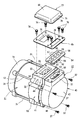
図1に示すように、インバータ一体形回転電機は、回転電機部11および回転電機部11の端部に接続されたインバータ部12を備えている。回転電機部11は、ステータ13、ロータ14、第1ハウジング15および第2ハウジング16を有する。ステータ13は円筒状のステータコア17とステータコア17のティース(図示せず)に巻装されたコイル18を備えている。コイル18の一部はステータコア17の両端面19、20から突出してコイルエンドを形成している。ロータ14はロータコア21とロータコア21の中心を貫通してロータコア21に固定された回転軸22とを備えている。回転軸22はロータコア21の一方の端面23から突出する第1軸部24とロータコア21の他方の端面25から突出する第2軸部26を有している。第1軸部24は回転軸22における出力側の軸部である。ロータ14の回転軸心Pは水平である。
As shown in FIG. 1, the inverter-integrated rotating electrical machine includes a rotating
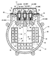
ステータコア17の一方の端面19には、第1ハウジング15が接合されている。第1ハウジング15はステータコア17の端面19および端面19側のコイルエンドを覆う。第1ハウジング15には軸孔27が形成されており、第1軸部24は軸受28を介して第1ハウジング15に支持されている。ステータコア17の他方の端面20には、第2ハウジング16が接合されている。第2ハウジング16はステータコア17の端面20および端面20側のコイルエンドを覆う。第2ハウジング16の内壁中心付近には第2軸部26と対向するように凹部29が形成されており、第2軸部26は、凹部29に設けられた軸受30を介して第2ハウジング16に支持されている。図2に示すように、第1ハウジング15および第2ハウジング16は、通しボルト31の締結によりステータ13に固定されている。
A
図2に示すように、第2ハウジング16は、回転軸心Pの径方向に隆起した台座部32を備えている。台座部32には矩形状の頂面33が形成されている。頂面33には回転軸心Pの径方向に開口する開口部34が形成されている。開口部34は、端面20側のコイルエンドに接続されている引出線35を第2ハウジング16の外部へ引き出すための開口部である。引出線35は3相(U相、V相、W相)に対応する3本の引出線35U、35V、35Wを有する。引出線35の先端には端子36(36U、36V、36W)が備えられている。端子36は丸形圧着端子であり通孔を有する。なお、図2では、説明の便宜上、端子36の図示を省略して引出線35の一部のみを図示している。
As shown in FIG. 2, the
次に、回転電機部11を駆動するインバータ部12について説明する。図2に示すように、インバータ部12は締結ボルト37によって第2ハウジング16に接合されている。図1、図3に示すように、インバータ部12は、電子部品38および電子部品38が実装された基板39を有する回路ユニット40を備えている。電子部品38はIGBT等のスイッチング素子を含む。回路ユニット40は板状の支持部材41に支持されている。回路ユニット40は3相(U相、V相、W相)に対応して3個設けられている。支持部材41における回路ユニット40を支持する支持面42は回転軸心Pと直交する面となっている。図示はしないが、回路ユニット40以外の電子部品が支持部材41に支持されているほか、他の基板に実装されている。図3に示すように、回路ユニット40は回転軸心Pと直交する方向に引き出された接続端子43(43U、43V、43W)を備えている。接続端子43の詳細については後述する。図2に示すように、支持部材41は第2ハウジング16における台座部32の頂面33とほぼ同一面となる頂面44を備えている。頂面44は支持部材41の外周縁の一部を構成している。なお、支持部材41は電子部品38の熱を逃がすヒートマスとしての機能を有している。
Next, the
インバータ部12は、支持部材41に接合され、回路ユニット40および接続端子43を覆うインバータカバー45を備えている。インバータカバー45は、胴部46と底部47を備えた有底状のカバーである。図4に示すように、胴部46の端部には支持部材41に対して接合されるカバー接合面48が形成されている。カバー接合面48の内周縁および外周縁は閉曲線となっている。つまり、カバー接合面48は切れ目のない環状(無端状)の面である。カバー接合面48には、無端状の第1シール部材49が装着される環状溝50が形成されている。第1シール部材49は支持部材41とインバータカバー45との間の気密性を保ち、インバータカバー45内への水分や塵埃の進入を防止する。図4では、カバー接合面48をハッチングにより示す。
The
インバータカバー45の胴部46は、回転軸心Pの径方向に隆起した台座部51を備えている。台座部51は矩形状の頂面52を備えている。図2に示すように、台座部51の頂面52は、第2ハウジング16における台座部32の頂面33および支持部材41の頂面44よりも回転軸心Pに近い面である。頂面33、44、57における幅(回転軸心Pと直交する水平方向の長さ)は互いにほぼ同じである。台座部51の頂面52には、長円形状のカバー開口部53が形成されている。従って、カバー開口部53はカバー接合面48と離間した位置に形成されている。カバー開口部53は、台座部51において回転軸心Pの径方向に開口し、インバータカバー45の内部と外部を連通する。
The
カバー開口部53には端子保持部材54が装着されている。端子保持部材54は、絶縁性を有する樹脂により形成されており、図3、図5に示すように、本体部55と本体部55の一方の端部に一体形成されたフランジ部56を備えている。本体部55には3個の貫通孔57が形成されている。貫通孔57は接続端子43を保持するほか、後述する中継端子58の挿入を許容する貫通孔である。フランジ部56は頂面52に対応する大きさに設定されている。端子保持部材54がカバー開口部53に装着された状態では、図5に示すように、フランジ部56の表面59は頂面33、44とほぼ同一面となり、裏面60は頂面52に当接する。
A
本体部55の外周にはフランジ部56と当接するように第2シール部材61が装着されている。第2シール部材61はゴム等の弾性材料により形成されたOリングであり、カバー開口部53におけるインバータカバー45と端子保持部材54との間を密封し、インバータカバー45内への水分や塵埃の進入を防止する。図2に示すように、本体部55の他方の端部には、接続端子43の一部を挿入可能とする切欠62が形成されている。また、フランジ部56の表面には長円形状の溝63が形成されている。図5に示すように、溝63にはシール部材64が装着されている。シール部材64はフランジ部56の表面59と後述するプレート部材65との間を密封し、外部から貫通孔57への水分や塵埃の進入を防止する。
A
ここで、接続端子43について詳述する。接続端子43はバスバーであり、図3に示すように、3相に対応する3本のバスバーを備えている。接続端子43は、回路ユニット40と電気的に接続された板状の延在部66と、延在部66と接続された円柱状の先端部67を有している。先端部67は支持部材41の外周縁からはみ出ない位置に設定されている。インバータカバー45が支持部材41に接合されている状態では、先端部67はカバー開口部53と対向している。先端部67の中心には有底のねじ孔68が形成されている。先端部67の外周における先端側には周方向にわたって環状溝69が形成されている。先端部67の外周における延在部66側には径方向に突出する突出片70を備えている。環状溝69には第3シール部材71が装着されている。第3シール部材71はゴム等の弾性材料により形成されたOリングであり、接続端子43と端子保持部材54との間の密封し、インバータカバー45内への水分や塵埃の進入を防止する。
Here, the
次に、中継端子58について説明する。中継端子58は引出線35の端子36と接続端子43とを電気的に接続するための導電性の金属部材である。本実施形態の中継端子58は銅製である。図5に示すように、中継端子58は円筒状であり、中心に通孔72を備えている。中継端子58の外径は、端子保持部材54の貫通孔57の内径より僅かに小さく設定されている。中継端子58は、貫通孔57において引出線35の端子36と接続端子43との間に介在される。引出線35の端子36、接続端子43および中継端子58は固定ボルト73により互いに固定される。
Next, the
本実施形態では、第2ハウジング16における台座部32の頂面33および端子保持部材54にわたって当接するプレート部材65が設けられている。プレート部材65は、第2ハウジング16および支持部材41に対する引出線35の絶縁を図るために絶縁材料である樹脂により形成されている。プレート部材65は開口部34に対応する第1開口部74と、端子保持部材54の貫通孔57に対応する矩形状の第2開口部75とを有している。プレート部材65はボルト76により第2ハウジング16およびインバータカバー45に固定される。第1開口部74は引出線35の挿通を可能とし、第2開口部75は中継端子58および固定ボルト73の挿通を可能とする。
In the present embodiment, a
本実施形態では、プレート部材65と接合され、引出線35および固定ボルト73を覆うプレートカバー77が設けられている。プレートカバー77は絶縁材料である樹脂により形成されている。プレートカバー77は、プレート部材65の上面の外周部と接合される外周部78と、外周部78から立ち上がる立壁部79と、プレートカバー77の頂部を形成する天壁部80と、を備えている。プレートカバー77はボルト(図示せず)によりプレート部材65に固定される。プレート部材65とプレートカバー77との間には無端状のシール部材(図示せず)により隙間が埋められている。無端状のシール部材は、プレート部材65とプレートカバー77の間からプレートカバー77の内部への水分や塵埃の進入を防止する。
In the present embodiment, a
次に、本実施形態のインバータ一体形回転電機の組立手順について説明する。予め回転電機部11を組み立て、引出線35を開口部34から引き出しておく。また、支持部材41に回路ユニット40および接続端子43を予め組み付けておく。まず、支持部材41にインバータカバー45を取り付けるが、インバータカバー45はボルト(図示せず)の締結により支持部材41に固定される。インバータカバー45のカバー接合面48は支持部材41の支持面42に接合され、カバー接合面48と支持面42との間には第1シール部材49が介在される。第1シール部材49は支持部材41とインバータカバー45との間を密封する。
Next, the assembly procedure of the inverter-integrated rotating electrical machine of this embodiment will be described. The rotating
次に、端子保持部材54の本体部55をインバータカバー45の開口部34に挿入するとともに、端子保持部材54の貫通孔57に接続端子43の先端部67を挿入する。本体部55が開口部34に挿入されることにより、第2シール部材61がカバー開口部53における本体部55とインバータカバー45との間に介在される。接続端子43の先端部67が貫通孔57に挿入されることにより、第3シール部材71が貫通孔57における先端部67と本体部55との間に介在される。また、先端部67が貫通孔57に挿入されると、突出片70が本体部55の切欠62に挿入され、接続端子43は端子保持部材54に係止される。端子保持部材54はインバータカバー45に対して仮止め状態となる。
Next, the
次に、端子保持部材54がインバータカバー45に仮止めされた状態で、貫通孔57に中継端子58を挿入する。次に、インバータカバー45が接合された支持部材41を締結ボルト37により第2ハウジング16に取り付ける。支持部材41が第2ハウジング16に取り付けられることにより、インバータ部12は回転電機部11の端部に接続される。
Next, with the
次に、プレート部材65を第2ハウジング16の台座部32および端子保持部材54にわたって取り付ける。プレート部材65はボルト76の締結により台座部32および端子保持部材54に取り付けられる。仮止め状態にある端子保持部材54はプレート部材65の取り付けとともにボルト76の締結によりインバータカバー45に取り付けられる。
Next, the
プレート部材65の取り付け後に、引出線35を第1開口部74から引き出して端子36を対応する中継端子58に当接させつつ、固定ボルト73を端子36の通孔および中継端子58の通孔72に挿入し、先端部67のねじ孔68に螺入する。固定ボルト73の締結により、先端部67と中継端子58との当接と、引出線35の端子36と中継端子58との当接が図られる。つまり、固定ボルト73が締結された状態では、引出線35と接続端子43は中継端子58を介して電気的に接続される。端子保持部材54は切欠62に挿入された突出片70を介して固定ボルト73の締結時に生じるトルクの反力を受ける。
After the
固定ボルト73の締結により接続端子43と引出線35とが電気的に接続されると、プレートカバー77をボルト(図示せず)によりプレート部材65に取り付ける。プレートカバー77の外周部78とプレート部材65との間には無端状のシール部材(図示せず)が介在されている。プレートカバー77のプレート部材65への取り付けにより、インバータ一体形回転電機の組立が完了する。
When the
本実施形態に係るインバータ一体形回転電機は以下の作用効果を奏する。
(1)支持部材41とインバータカバー45との接合部と、インバータカバー45と端子保持部材54との接合部は互いに独立している。このため、無端状の第1シール部材49をカバー接合面48と支持部材41との間に介在できるほか、無端状の第2シール部材61をインバータカバー45と端子保持部材54との間に介在でき、インバータ部12におけるシール構造を簡素化できる。引出線35と接続端子43とは中継端子58を介して固定ボルト73により接続されているので、インバータ部12におけるシール構造を簡素化できるとともに、回転電機部11に対してインバータ部12を着脱することができる。従って、回転電機部11やインバータ部12の保守が行い易い。
The inverter-integrated rotating electrical machine according to the present embodiment has the following effects.
(1) The joint between the
(2)無端状の第3シール部材71が接続端子43と端子保持部材54との間に介在されるため、第3シール部材71により接続端子43と端子保持部材54との間を通じて水分・塵埃がインバータカバー45の内部へ入り込むことが防止される。
(2) Since the endless
(3)端子保持部材54に係止される係止部としての突出片70が接続端子43に設けられるため、突出片70が係止される端子保持部材54は、固定ボルト73の締結により生じるトルクの反力を受けることができる。このため、固定ボルト73のトルクの反力が接続端子43と回路ユニット40との接続箇所に集中することがなく、接続端子43の変形や破損を防止することができる。
(3) Since the protruding
(4)端子保持部材54には突出片70が挿入可能な切欠62が設けられている。固定ボルト73の締結時に突出片70が切欠62に挿入されることにより、接続端子43の先端部67が貫通孔57にて固定ボルト73と共回りすることがない。
(4) The
(第2の実施形態)
次に、第2の実施形態に係るインバータ一体形回転電機について説明する。本実施形態は、引出線と中継端子が一体化されている点で第1の実施形態と異なる。本実施形態では、第1の実施形態と共通する構成については、第1の実施形態の説明を援用し、同じ符号を用いる。
(Second Embodiment)
Next, an inverter-integrated dynamoelectric machine according to a second embodiment will be described. This embodiment is different from the first embodiment in that the leader line and the relay terminal are integrated. In this embodiment, about the structure which is common in 1st Embodiment, description of 1st Embodiment is used and the same code | symbol is used.
図6に示すように、引出線35の端子91は、端子金具92と端子金具92にろう付けされた中継端子93を有する。端子金具92は丸形圧着端子であり円形の通孔92Aを有する。中継端子93は通孔94を備えており、通孔94は端子金具92の通孔92Aと同軸となるように端子金具92に固定されている。従って、中継端子93は引出線35と一体化されている。本実施形態では、プレート部材65を第2ハウジング16およびインバータカバー45に取り付けた後に、引出線35と一体化されている中継端子93が貫通孔57に挿通され、その後に固定ボルト73により接続端子43と接続される。
As shown in FIG. 6, the
本実施形態は、第1の実施形態の作用効果と同等の作用効果を奏する。また、引出線35が中継端子93と一体化されることにより部品点数を削減することができる。また、部品点数の削減により回転電機部11に対してインバータ部12の着脱がより容易となる。
This embodiment has the same operational effects as those of the first embodiment. Further, the
本発明は、上記の実施形態に限定されるものではなく発明の趣旨の範囲内で種々の変更が可能であり、例えば、次のように変更してもよい。 The present invention is not limited to the above-described embodiment, and various modifications are possible within the scope of the gist of the invention. For example, the following modifications may be made.
○ 上記の実施形態では、端子保持部材54とプレート部材65とを個々に設けるようにしたが、この限りではない。例えば、図7に示すように、端子保持部材にプレート部材が一体化され、プレート部材の機能を兼ねた端子保持部材95としてもよい。端子保持部材95は本体部96およびフランジ部97を備え、フランジ部97の一部が第2ハウジング16まで延在する。フランジ部97には引出線35の引出しを許容するフランジ開口部98を備えている。フランジ開口部98はプレート部材65の第1開口部74に相当する。本体部96には接続端子43および中継端子58が挿通される貫通孔99を備える。端子保持部材95とする場合、端子保持部材とプレート部材の一体化およびシール部材64の不要により部品点数を削減することができる。
○ 上記の実施形態では、端子保持部材に切欠を設けたがこの限りではない。切欠は必須の構成ではなく、切欠が設けられない端子保持部材であってもよい。係止部の形状は突出片の形状に限定されず、接続端子は少なくとも端子保持部材に係止される係止部を備えればよい。
In the above embodiment, the
In the above embodiment, the terminal holding member is notched, but this is not the case. The notch is not an essential configuration, and may be a terminal holding member that is not provided with a notch. The shape of the locking portion is not limited to the shape of the protruding piece, and the connection terminal may include at least a locking portion locked to the terminal holding member.
10 スタッカクレーン
11 回転電機部
12 インバータ部
15 第1ハウジング
16 第2ハウジング
17 ステータコア
21 ロータコア
35(35U、35V、35W) 引出線
37 締結ボルト
38 電子部品
39 基板
40 回路ユニット
41 支持部材
43(43U、43V、43W) 接続端子
45 インバータカバー
48 カバー接合面
49 第1シール部材
53 カバー開口部
54、95 端子保持部材
57、99 貫通孔
58、93 中継端子
61 第2シール部材
62 切欠(端子保持部材)
67 先端部
68 ねじ孔
69 環状溝
70 突出片
71 第3シール部材
72 通孔(中継端子)
73 固定ボルト
98 フランジ開口部
99 貫通孔
P 回転軸心
DESCRIPTION OF SYMBOLS 10
67
73
Claims (4)
前記回転電機部の端部に接続され、前記回転電機部を駆動するインバータ部と、を備え、
前記インバータ部は、
電子部品および前記電子部品が実装された基板を有する回路ユニットと、
前記ハウジングに固定され、前記回路ユニットを支持する支持部材と、
前記回路ユニットから前記ロータの回転軸心と直交する方向へ引き出された接続端子と、
前記支持部材に接合され、前記回路ユニットおよび前記接続端子を覆うインバータカバーと、
前記接続端子を保持する端子保持部材と、を備え、
前記回転電機部から前記インバータ部へ向けて引き出された引出線と前記接続端子が電気的に接続されるインバータ一体形回転電機であって、
前記インバータカバーに形成され、前記支持部材に対して接合される無端状のカバー接合面と、
前記カバー接合面と前記支持部材との間に介在される無端状の第1シール部材と、
前記インバータカバーにて前記カバー接合面と離間した位置に形成され、前記端子保持部材が装着されるカバー開口部と、
前記カバー開口部において前記インバータカバーと前記端子保持部材との間に介在される無端状の第2シール部材と、
前記端子保持部材に形成され、前記接続端子が挿入される貫通孔と、
前記貫通孔に挿入され、前記引出線と前記接続端子との間に介在される中継端子と、を備えることを特徴とするインバータ一体形回転電機。 A rotating electrical machine having a stator, a rotor and a housing;
An inverter connected to an end of the rotating electrical machine and driving the rotating electrical machine,
The inverter unit is
A circuit unit having an electronic component and a substrate on which the electronic component is mounted;
A support member fixed to the housing and supporting the circuit unit;
A connection terminal drawn out from the circuit unit in a direction perpendicular to the rotational axis of the rotor;
An inverter cover joined to the support member and covering the circuit unit and the connection terminal;
A terminal holding member for holding the connection terminal,
An inverter-integrated dynamoelectric machine in which the lead wire drawn out from the dynamo-electric machine unit toward the inverter unit and the connection terminal are electrically connected,
An endless cover joining surface formed on the inverter cover and joined to the support member;
An endless first seal member interposed between the cover joint surface and the support member;
A cover opening formed in the inverter cover at a position separated from the cover joint surface, and to which the terminal holding member is mounted;
An endless second seal member interposed between the inverter cover and the terminal holding member at the cover opening;
A through hole formed in the terminal holding member and into which the connection terminal is inserted;
An inverter-integrated dynamoelectric machine comprising: a relay terminal inserted into the through hole and interposed between the lead wire and the connection terminal.
前記接続端子に設けられ、前記端子保持部材に係止される係止部と、を備えたことを特徴とする請求項1又は2記載のインバータ一体形回転電機。 A fixing bolt for fastening the lead wire, the relay terminal, and the connection terminal;
The inverter-integrated dynamoelectric machine according to claim 1, further comprising: a locking portion that is provided on the connection terminal and is locked to the terminal holding member.
Priority Applications (1)
| Application Number | Priority Date | Filing Date | Title |
|---|---|---|---|
| JP2016116310A JP2017221083A (en) | 2016-06-10 | 2016-06-10 | Inverter integrated rotary electric machine |
Applications Claiming Priority (1)
| Application Number | Priority Date | Filing Date | Title |
|---|---|---|---|
| JP2016116310A JP2017221083A (en) | 2016-06-10 | 2016-06-10 | Inverter integrated rotary electric machine |
Publications (1)
| Publication Number | Publication Date |
|---|---|
| JP2017221083A true JP2017221083A (en) | 2017-12-14 |
Family
ID=60657869
Family Applications (1)
| Application Number | Title | Priority Date | Filing Date |
|---|---|---|---|
| JP2016116310A Pending JP2017221083A (en) | 2016-06-10 | 2016-06-10 | Inverter integrated rotary electric machine |
Country Status (1)
| Country | Link |
|---|---|
| JP (1) | JP2017221083A (en) |
Cited By (7)
| Publication number | Priority date | Publication date | Assignee | Title |
|---|---|---|---|---|
| WO2020016911A1 (en) * | 2018-07-17 | 2020-01-23 | 三菱電機株式会社 | Rotating electric machine |
| WO2020040278A1 (en) * | 2018-08-24 | 2020-02-27 | 日本電産エレシス株式会社 | Inverter unit and motor unit |
| WO2020105385A1 (en) * | 2018-11-20 | 2020-05-28 | 住友電装株式会社 | Connector |
| JP2021052499A (en) * | 2019-09-25 | 2021-04-01 | 株式会社明電舎 | Rotary machine |
| DE102020129134A1 (en) | 2020-11-05 | 2022-05-05 | Audi Aktiengesellschaft | Protective device for a pulse-controlled inverter |
| FR3125179A1 (en) * | 2021-07-12 | 2023-01-13 | Safran Electrical & Power | MODULAR INTERCONNECTIONS OF A MOTOR AND POWER ELECTRONICS |
| JP7528836B2 (en) | 2021-03-24 | 2024-08-06 | 株式会社明電舎 | Rotating Machine |
-
2016
- 2016-06-10 JP JP2016116310A patent/JP2017221083A/en active Pending
Cited By (13)
| Publication number | Priority date | Publication date | Assignee | Title |
|---|---|---|---|---|
| JPWO2020016911A1 (en) * | 2018-07-17 | 2020-12-17 | 三菱電機株式会社 | Rotating machine |
| CN112385123A (en) * | 2018-07-17 | 2021-02-19 | 三菱电机株式会社 | Rotating electrical machine |
| WO2020016911A1 (en) * | 2018-07-17 | 2020-01-23 | 三菱電機株式会社 | Rotating electric machine |
| WO2020040278A1 (en) * | 2018-08-24 | 2020-02-27 | 日本電産エレシス株式会社 | Inverter unit and motor unit |
| US11742608B2 (en) | 2018-11-20 | 2023-08-29 | Sumitomo Wiring Systems, Ltd. | Connector |
| WO2020105385A1 (en) * | 2018-11-20 | 2020-05-28 | 住友電装株式会社 | Connector |
| JP2021052499A (en) * | 2019-09-25 | 2021-04-01 | 株式会社明電舎 | Rotary machine |
| DE102020129134A1 (en) | 2020-11-05 | 2022-05-05 | Audi Aktiengesellschaft | Protective device for a pulse-controlled inverter |
| DE102020129134B4 (en) | 2020-11-05 | 2022-05-25 | Audi Aktiengesellschaft | Protective device for a pulse-controlled inverter |
| US11791742B2 (en) | 2020-11-05 | 2023-10-17 | Audi Ag | Protection device for a pulse inverter |
| JP7528836B2 (en) | 2021-03-24 | 2024-08-06 | 株式会社明電舎 | Rotating Machine |
| FR3125179A1 (en) * | 2021-07-12 | 2023-01-13 | Safran Electrical & Power | MODULAR INTERCONNECTIONS OF A MOTOR AND POWER ELECTRONICS |
| WO2023285744A1 (en) * | 2021-07-12 | 2023-01-19 | Safran Electrical & Power | Modular interconnections for a motor and a power electronic unit |
Similar Documents
| Publication | Publication Date | Title |
|---|---|---|
| JP2017221083A (en) | Inverter integrated rotary electric machine | |
| US11258330B2 (en) | Rotating electrical device | |
| JP5186180B2 (en) | Brushless motor | |
| JP5354889B2 (en) | Brushless motor | |
| JP5518255B2 (en) | Drive unit-integrated rotating electrical machine | |
| US10597069B2 (en) | Control unit and electric power steering device employing control unit | |
| JP6058164B2 (en) | Rotating electric machine | |
| JP4954271B2 (en) | Rotating electric machine | |
| CN108377080B (en) | Drive device | |
| JP6610225B2 (en) | Drive device | |
| KR20100093597A (en) | Electric power steering apparatus | |
| JP6536499B2 (en) | Motor device | |
| WO2018150964A1 (en) | Motor and pump device | |
| JP2017139830A (en) | Driving device | |
| JP2015104283A (en) | Connector for motor and connector assembly for motor | |
| JPWO2014080675A1 (en) | Electric motor, air conditioner, and method of manufacturing electric motor | |
| WO2018051988A1 (en) | Motor | |
| WO2017033298A1 (en) | Terminal block of rotating electric machine | |
| JP2010011601A (en) | Terminal unit for electric motor | |
| JP4564982B2 (en) | Rotating electric machine | |
| US11677290B2 (en) | Motor | |
| TWI768609B (en) | Rotary motor | |
| US20140070643A1 (en) | Rotating electric machine | |
| CN113169627A (en) | Electric drive device | |
| WO2021106675A1 (en) | Electric motor |