JP2017220014A - Card processing device and automated teller machine - Google Patents
Card processing device and automated teller machine Download PDFInfo
- Publication number
- JP2017220014A JP2017220014A JP2016113642A JP2016113642A JP2017220014A JP 2017220014 A JP2017220014 A JP 2017220014A JP 2016113642 A JP2016113642 A JP 2016113642A JP 2016113642 A JP2016113642 A JP 2016113642A JP 2017220014 A JP2017220014 A JP 2017220014A
- Authority
- JP
- Japan
- Prior art keywords
- magnetic field
- magnetic
- disturbing
- card
- loop antenna
- Prior art date
- Legal status (The legal status is an assumption and is not a legal conclusion. Google has not performed a legal analysis and makes no representation as to the accuracy of the status listed.)
- Pending
Links
Images


Abstract
Description
本発明は、カード処理装置及び自動取引装置に関し、磁界発生部を備えたカード処理装置及び自動取引装置に適用して好適なるものである。 The present invention relates to a card processing device and an automatic transaction device, and is suitable for application to a card processing device and an automatic transaction device each having a magnetic field generator.
ATM(現金自動預金支払機)などの取引処理装置には、磁気カードもしくはIC(Integrated Circuit)カードに対して情報の処理を行うカード処理装置が搭載されている。このカード処理装置は、カード挿入排出口から挿入された磁気カードもしくはICカードを本体内に取り込んで、磁気カードの磁気ストライプに記録された磁気情報を磁気ヘッドで読み込んだり、ICカードのICチップに記録された情報を読み込んだりする。そして、取引終了後に、磁気カードもしくはICカードを本体内からカード挿入排出口へ排出する。 2. Description of the Related Art A transaction processing device such as an ATM (automatic cash dispenser) is equipped with a card processing device that processes information on a magnetic card or an IC (Integrated Circuit) card. This card processing device takes a magnetic card or IC card inserted from the card insertion / ejection slot into the main body, reads the magnetic information recorded on the magnetic stripe of the magnetic card with a magnetic head, or puts it on the IC chip of the IC card. Read the recorded information. Then, after the transaction is completed, the magnetic card or IC card is discharged from the main body to the card insertion / discharge port.
ATMにおいて、磁気ヘッドを備えた偽のカード挿入排出口を有する不正装置を、正規のカード挿入排出口に被せるように設置して、磁気カードの磁気情報を不正に取得する、スキミングと呼ばれる犯罪がある。また、カードリーダ内の磁気ヘッドから磁気カードの磁気情報を不正に取得するスキミングの方法もある。 In an ATM, a crime called skimming, in which a fraudulent device having a fake card insertion / extraction port equipped with a magnetic head is placed over the regular card insertion / extraction port and the magnetic information of the magnetic card is illegally obtained. is there. There is also a skimming method in which the magnetic information of the magnetic card is illegally acquired from the magnetic head in the card reader.
スキミングの防止対策として、例えば、磁界発生部により正規のカード挿入排出口の近傍に磁界を発生させて、不正装置の磁気ヘッドで磁気カードの磁気情報が読み取られるのを妨害する技術がある(例えば特許文献1)。 As a countermeasure against skimming, for example, there is a technique for generating a magnetic field in the vicinity of a regular card insertion / extraction port by a magnetic field generation unit and preventing magnetic information of a magnetic card from being read by a magnetic head of an unauthorized device (for example, Patent Document 1).
上記技術1を利用したカード処理装置は、スキマーを妨害するために、妨害磁界を発生させているが、自身の磁気ヘッドに対しても磁気読取りを妨害してしまうため、自身の磁気情報読取時には、妨害磁界を止める処理を行っている。 The card processing device using the above technique 1 generates a disturbing magnetic field in order to disturb the skimmer. However, since the magnetic reading is disturbed to its own magnetic head, when reading its own magnetic information. In order to stop the disturbing magnetic field.
また、カード挿入口に電磁界を常に発生した状態で、自身の磁気情報読取時に、磁気情報の書き込まれているトラックの妨害磁界ノイズが重畳された信号から、磁気情報の書き込まれていないトラックの妨害磁界ノイズの信号を引くことにより、妨害磁界ノイズを除去し、磁気情報信号を再現し磁気情報を読取る技術がある(例えば特許文献2)。 In addition, when an electromagnetic field is constantly generated at the card insertion slot, when reading magnetic information of itself, a signal on which the magnetic field information is written is superimposed on the track on which no magnetic information is written. There is a technique for reading out magnetic information by reproducing the magnetic information signal by removing the interference magnetic field noise by drawing the signal of the interference magnetic field noise (for example, Patent Document 2).
さらに、カード挿入口に電磁界を常に発生した状態で、自身の磁気情報読取時に、妨害磁界のノイズが重畳された磁気情報信号から、妨害磁界を制御しているデジタル信号を引くことにより、ノイズを除去し、磁気情報信号を再現する技術がある(例えば特許文献3)。 Furthermore, when an electromagnetic field is constantly generated at the card insertion slot, when reading magnetic information of itself, a digital signal that controls the disturbing magnetic field is subtracted from the magnetic information signal on which the disturbing magnetic field noise is superimposed. There is a technique for removing the signal and reproducing the magnetic information signal (for example, Patent Document 3).
しかし、上記特許文献1を利用したカード処理装置は、スキマーを妨害するために、妨害磁界を発生させているが、自身の磁気情報読取時には、妨害磁界を止める処理が必要であり、磁気情報の全てもしくは一部をスキマーに読まれてしまうという課題がある。 However, the card processing apparatus using Patent Document 1 generates a disturbing magnetic field in order to disturb the skimmer. However, when reading the magnetic information of the card processing apparatus, a process for stopping the disturbing magnetic field is necessary. There is a problem that all or part of it is read by a skimmer.
また、上記特許文献2を利用したカード処理装置は、磁気カードの全てのトラックに各々同一でない磁気情報が書き込まれており、妨害磁界をランダム発生させている場合、意図しない信号を引いてしまうために、磁気情報信号が再現できず磁気情報を読取ることができないという課題がある。加えて、上記技術2の別の実施の形態では、磁気情報を読取る磁気ヘッドとは別に磁気ヘッドが新たに必要で、構成が複雑になるという課題がある。
Further, the card processing device using the above-mentioned
また、上記特許文献3を利用したカード処理装置は、妨害磁界が周囲の磁性体や環境温度によって変化しても、妨害磁界を制御しているデジタル信号は変化しない、加えて、カード処理装置とは別の妨害磁界発生装置を取り付けた場合も、妨害磁界を制御しているデジタル信号は変化しないため、磁界のノイズが重畳された磁気情報信号から、妨害磁界を制御しているデジタル信号を引いても磁気情報信号が再現できず磁気情報を読取ることができないという課題がある。さらに、減算処理を行うためのDSP(Digital Signal Processor)が必要で、構成が複雑になるという課題がある。
Further, the card processing device using the above-mentioned
本発明は以上の点を考慮してなされたもので、不正装置による磁気カードの磁気情報の不正な読み取り(スキミング)を防止しつつ、磁気カードの磁気情報を読取ることができるカード処理装置及び自動取引装置を提供することである。 The present invention has been made in consideration of the above points, and a card processing apparatus capable of reading magnetic information on a magnetic card while preventing unauthorized reading (skimming) of magnetic information on the magnetic card by an unauthorized device, and an automatic processing apparatus. It is to provide a transaction apparatus.
かかる課題を解決するために本発明においては、磁気カードの挿入排出口となる開口部と、前記開口部近傍に設けられて、電磁界の変化に応じて信号を出力する磁気ヘッドと、前記開口部近傍に妨害磁界を放射する1又は複数の磁界発生部と、前記磁界発生部から放射される妨害磁界に対応した電圧を検出して検出信号を出力する1又は複数の電圧検出部と、前記磁気ヘッドの出力信号と前記電圧検出部の検出による検出信号を取り込んで処理する処理部と、を備え、前記処理部は、前記磁気ヘッドの出力信号から前記電圧検出部の検出による検出信号を減算処理し、当該減算処理後の信号から磁気情報を読取ることを特徴とする。 In order to solve this problem, in the present invention, an opening serving as an insertion / extraction opening for a magnetic card, a magnetic head provided in the vicinity of the opening and outputting a signal in accordance with a change in an electromagnetic field, and the opening One or more magnetic field generators that radiate a disturbing magnetic field in the vicinity of the unit, one or more voltage detectors that detect a voltage corresponding to the disturbing magnetic field radiated from the magnetic field generator and output a detection signal; A processing unit that captures and processes the output signal of the magnetic head and the detection signal detected by the voltage detection unit, and the processing unit subtracts the detection signal detected by the voltage detection unit from the output signal of the magnetic head And magnetic information is read from the signal after the subtraction process.
かかる構成によれば、磁界発生部から開口部近傍に妨害磁界を放射することで、開口部近傍に配置された磁気ヘッドと不正装置には妨害磁界によるノイズが与えられるが、処理部は、磁気ヘッドの出力信号から、電圧検出部の検出による検出信号を減算処理することで、磁気ヘッドの出力信号に重畳した妨害ノイズを除去し、妨害ノイズが除去された信号から磁気情報を読取ることができる。 According to such a configuration, by radiating a disturbing magnetic field from the magnetic field generation unit in the vicinity of the opening, noise due to the disturbing magnetic field is given to the magnetic head and the unauthorized device disposed in the vicinity of the opening. By subtracting the detection signal detected by the voltage detector from the output signal of the head, the interference noise superimposed on the output signal of the magnetic head can be removed, and the magnetic information can be read from the signal from which the interference noise has been removed. .
また、かかる課題を解決するために本発明においては、上記カード処理装置を搭載した自動取引装置が提供される。 Moreover, in order to solve this subject, in this invention, the automatic transaction apparatus carrying the said card processing apparatus is provided.
本発明によれば、不正装置による磁気カードの磁気情報の不正な読み取り(スキミング)を防止しつつ、磁気カードの磁気情報を読取ることができる。 According to the present invention, magnetic information on a magnetic card can be read while preventing unauthorized reading (skimming) of magnetic information on the magnetic card by an unauthorized device.
以下図面について、本発明の一実施の形態を詳述する。 Hereinafter, an embodiment of the present invention will be described in detail with reference to the drawings.
(1)第1の実施の形態
(1−1)カード処理装置の構成
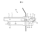
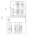
まず、本実施の形態にかかるカード処理装置100の構成について、図1および図2を参照して説明する。図1は、本発明の第1の実施の形態に係るカード処理装置の構成を示すブロック図であり、図2は、同実施の形態にかかるカード処理装置の概略構造図である。
(1) First Embodiment (1-1) Configuration of Card Processing Device First, the configuration of a
カード処理装置100は、例えば、金融機関に設置されたATM(Automatic Teller Machine)などに搭載される。カード処理装置100は、顧客が所有する磁気カードを受け付けて、磁気カードに記録された磁気情報を読み取るカードリーダから構成されている。
The
図1に示すように、カード処理装置100は、制御部2、記憶部3、磁気読み取り部4、カード位置検出センサ6、ホストインタフェイス7、カード挿入検出センサ8、カードロック駆動部9及び妨害発生ユニット10を含む。
As shown in FIG. 1, the
妨害発生ユニット10は、磁界制御部13、ループアンテナ12を備える磁界発生部11、ループアンテナ電圧検出部21を含む。
The
制御部2は、マイクロコンピュータ(CPU)から構成され、記憶部3に格納されたプログラムに従って各部の動作を制御する。記憶部3は、メモリから構成され、各種の情報やプログラムを記憶している。磁気読み取り部4は、図2に示すように、磁気ヘッド4aと、磁気ヘッド4aを駆動するための回路(図示せず)から構成されている。磁気読み取り部4は、本体1内で磁気ヘッド4aにより磁気カード200の磁気ストライプから磁気情報を読み取る。
The
カード位置検出センサ6は、図2に示すように、1つもしくは2つ以上の光センサ(発光素子と受光素子を含む)6aから構成されている。制御部2は、各カード位置検出センサ6の出力状態に基づいて、本体1内における磁気カード200の位置を検知する。ホストインタフェイス7は、ATMに情報を送受信する回路から構成されている。
As shown in FIG. 2, the card
カード挿入検出センサ8は、図2に示すように、1つの光センサ(発光素子と受光素子を含む)8aから構成されている。カード挿入検出センサ8は、磁気カード200の挿入排出口となる開口部20から挿入された磁気カード200を検出し、検出信号を制御部2に出力する。制御部2は、カード挿入検出センサ8の出力状態に基づいて、カード処理装置100への磁気カード200の挿入を検知する。カードロック駆動部9は、図2に示すように、カードロックレバー9aを、開口部20に連なるカード搬送路に出し入れさせるためのソレノイドや回路(図示せず)から構成されている。
As shown in FIG. 2, the card
次に、妨害発生ユニット10の詳細について説明する。磁界発生部11には、ループアンテナ12と、ループアンテナ12を駆動するための回路(図示せず)が含まれている。磁界発生部11は、磁気ヘッド4aより開口部20側であって、磁気ヘッド4aの前方に配置されると共に、開口部20の上方に配置される。磁界発生部11は、ループアンテナ12に電流を流すことにより、ループアンテナ12から開口部20の周囲に妨害磁界を放射させる。
Next, details of the
磁界制御部13は、例えば、制御部2からの指令(制御信号)を基に磁界発生部11のループアンテナ12からの妨害磁界の発生および停止を制御する。
For example, the magnetic
ループアンテナ電圧検出部21は、ループアンテナ12に直接接続されており、ループアンテナ12の電圧を検出して制御部2に送信する。ループアンテナ12の電圧は妨害磁界を示すものであり、制御部2は、ループアンテナ12の電圧を監視することにより、妨害磁界の状態を読取ることができる。
The loop antenna
制御部2は、ループアンテナ12の電圧に基づいてループアンテナ12から放射される妨害磁界の状態を制御し、妨害磁界が正常に出力されているか否かを監視する。
The
このように、妨害発生ユニット10をカード処理装置100に内蔵して、磁界発生部11により妨害磁界を発生させることで、不正装置による磁気カード200の磁気情報の不正な読み取り(スキミング)を防止することができる。
As described above, the
(1−2)磁気カード読取り時の動作
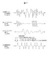
次に、図3及び図4を参照して、本実施の形態にかかる磁気カード読取り時の動作について説明する。図3は、本実施の形態にかかるカード処理装置の磁気情報読取り動作を示す説明図であり、図4は、本実施の形態にかかるカード処理装置の磁気情報読取り動作を示すタイムチャートである。なお、磁気カード読取り時の動作の説明に際し、適宜、図1及び図2を参照する。
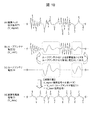
(1-2) Operation at the time of reading the magnetic card Next, with reference to FIG. 3 and FIG. 4, the operation at the time of reading the magnetic card according to the present embodiment will be described. FIG. 3 is an explanatory diagram showing the magnetic information reading operation of the card processing device according to the present embodiment, and FIG. 4 is a time chart showing the magnetic information reading operation of the card processing device according to the present embodiment. In describing the operation at the time of reading the magnetic card, FIGS. 1 and 2 will be referred to as appropriate.
図3に示すように、カード処理装置100に取り付けられたスキマーの磁気ヘッド30aから、または、自身の磁気ヘッド4aからのスキミングを防止するために、妨害発生ユニット10内のループアンテナ12に電流を流すことにより、ループアンテナ12から開口部20の周囲に妨害磁界を放射する。この妨害磁界は、スキマーの磁気ヘッド30aだけでなく、自身の磁気ヘッド4aに対してもノイズ(ノイズ信号)を与える。この際、ループアンテナ12の長さ方向の中心と磁気ヘッド30aの幅方向の中心が、磁気カード200の搬送路を間にして同一直線上となるように、ループアンテナ12と磁気ヘッド30aが配置される場合、ループアンテナ12から磁気ヘッド30aに強い妨害磁界を放射することができる。
As shown in FIG. 3, in order to prevent skimming from the
制御部2は、ループアンテナ電圧52に基づいてループアンテナ12から放射される妨害磁界の状態を制御するために、ループアンテナ電圧52を取り込んで、ループアンテナ12から、妨害磁界が正常に放射されているか否かの監視、即ち磁界出力監視2aを実行する。
In order to control the state of the disturbing magnetic field radiated from the
この状態でカード処理装置100に挿入された磁気カード200の磁気ストライプが磁気ヘッド4aに到達すると、磁気ヘッド4aから信号が出力される。磁気ヘッド4aから出力される信号には、磁気ストライプに書き込まれた磁気信号に加え、ループアンテナ12から放射された妨害磁界のノイズ(ノイズ信号)が重畳されている。妨害磁界によるノイズが重畳された磁気信号であって、増幅回路50で増幅された磁気信号を、図4(a)の磁気ヘッド出力信号51に、ループアンテナ12の電圧を、図4(b)のループアンテナ電圧52に示す。
In this state, when the magnetic stripe of the
制御部2は、磁気ヘッド出力信号51からループアンテナ電圧52を減算する減算処理2bを実行し、磁気ヘッド出力信号51に重畳されていた妨害磁界のノイズを除去し、減算処理後の信号を、図4(c)の減算処理後信号53として出力する。
The
制御部2は、妨害磁界のノイズ(ノイズ信号)が除去された減算処理後信号53を使って、磁気情報を読み取るための磁気読取処理2cを行い、磁気読取処理2cで得られた磁気情報を、ホストインタフェイス7を介して、上位装置(ATM)に送信する通信処理2dを実行する。
The
一方、ループアンテナ12から発生する妨害磁界が、磁気ヘッド30aに常時作用することから、スキマーの磁気ヘッド30aは、磁気カード200の磁気情報を読み取ることができない。
On the other hand, since the disturbing magnetic field generated from the
磁気ヘッド4aは、ループアンテナ12からの妨害磁界によりノイズ信号を出力するが、環境温度の変化や周囲の磁性体の配置により、妨害磁界の強度が変化するため、磁気ヘッド4aから出力されるノイズ信号も変化する。この時、妨害磁界の強度の変化に合わせてループアンテナ電圧52も変化することを利用することができる。つまり、周囲の環境によって、磁気ヘッド4aのノイズレベルが変化しても、ループアンテナ電圧52の出力(レベル)が変化することにより、正しくノイズを除去し、磁気情報の読取り処理を行うことができる。
The
ループアンテナ電圧検出部21は、妨害磁界が正常に放射されているか否かを監視するために、既存のカード処置装置に存在する場合、本実施の形態では、新たな構成を加えることなく、妨害磁界を放射しつつ、磁気読取り動作を行うことができる。
When the loop antenna
妨害磁界の放射タイミングについては、常時放射する場合だけではなく、利用者がATMの前に立ったときに、ATMからカード処理装置100に起動指令が送信されるようにしてもよい。そして、この起動指令をホストインタフェイス7を介して受信した制御部2が、磁界制御部13に磁界発生指令を送信し、磁界発生部11により妨害磁界を放射させてもよい。この場合、妨害発生ユニット10への磁気カード200の挿入前から、磁界発生部11により妨害磁界が放射させてもよい。
Regarding the radiation timing of the disturbing magnetic field, not only when always radiating, but also when the user stands in front of the ATM, an activation command may be transmitted from the ATM to the
また、カード挿入検出センサ8によりカード処理装置100内に磁気カード200が取り込まれたことが検知されると、制御部2が、磁界制御部13に磁界出力指令を送信する。磁界制御部13は、磁界出力指令を受信すると、磁界発生部11によりループアンテナ12からの妨害磁界の放射を開始させる。他の例として、妨害磁界を所定時間放射した後、妨害磁界の放射を停止させるようにしてもよい。
When the card
また、カード位置検出センサ6によりカード処理装置100から磁気カード200が引き抜かれたことが検知されると、制御部2が、磁界制御部13に磁界出力指令を送信する。磁界制御部13は、磁界出力指令を受信すると、磁界発生部11によりループアンテナ12からの妨害磁界の放射を開始させる。他の例として、妨害磁界を所定時間放射した後、妨害磁界の放射を停止させるようにしてもよい。
When the card
(1−3)本実施の形態の効果
本実施の形態によれば、自身の磁気ヘッド4aに重畳されたノイズ(ノイズ信号)を正確に除去できるため、常時、妨害磁界を照射し、スキミング装置から磁気情報を読み取られるのを防止しつつ、自身は磁気情報を読取ることができる。
(1-3) Effects of this Embodiment According to this embodiment, noise (noise signal) superimposed on its own
また、環境温度の変化や周辺の磁性体の配置によって自身の磁気ヘッド4aに重畳されるノイズ(ノイズ信号)が変化した場合でも、ループアンテナ電圧52も同様に変化するため、ノイズ(ノイズ信号)を除去し、磁気情報を正確に読取ることができる。
Further, even when the noise (noise signal) superimposed on the
また、ループアンテナ電圧52は、磁界発生部11の故障を監視するため、常に検出していた信号であり、既存のカード処置装置にループアンテナ電圧検出部21が存在する場合、新たに構成を追加することなく、ノイズ(ノイズ信号)を除去し、磁気情報を読取ることができる。
Further, the
(2)第2の実施の形態
(2−1)カード処理装置の構成
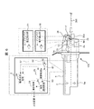
次に、第2の実施の形態について説明する。本実施の形態にかかるカード処理装置100の構成における、第1の実施の形態と同様箇所については詳細な説明は省略し、以下では、第1の実施の形態と異なる妨害発生ユニット10に係わる構成および動作について詳細に説明する。図5は、本発明の第2の実施の形態にかかるカード処理装置の構成を示すブロック図である。
(2) Second Embodiment (2-1) Configuration of Card Processing Device Next, a second embodiment will be described. In the configuration of the
まず、図5に示すように、妨害発生ユニット10は、スキマーへの妨害性能を向上するため、磁界制御部13、磁界発生部11、ループアンテナ電圧検出部21の他に、磁界発生部11とは異なる妨害磁界を発生する磁界発生部16と、磁界発生部16に属するループアンテナ17の電圧を検出するループアンテナ電圧検出部26とを有し、磁界発生部16が磁界制御部13に接続される。磁界発生部およびループアンテナ電圧検出部は2つに限らず、3以上有する場合でもよい。
First, as shown in FIG. 5, the
磁界発生部16には、ループアンテナ17と、ループアンテナ17を駆動するための回路(図示せず)が含まれている。磁界発生部16は、ループアンテナ17に電流を流すことにより、磁界発生部11のループアンテナ12から放射される妨害磁界とは異なる妨害磁界、例えば、周波数や放射レベル、放射間隔等が異なる妨害磁界を開口部20の周囲に放射させる。磁界発生部11およびループアンテナ電圧検出部21は第1の実施の形態と同様の構成のため、説明は省略する。
The
磁界制御部13は、例えば、制御部2からの指令(制御信号)を基に磁界発生部11のループアンテナ12からの妨害磁界と磁界発生部16のループアンテナ17からの妨害磁界の発生および停止を制御する。
For example, the magnetic
ループアンテナ電圧検出部26は、ループアンテナ17に直接接続されており、ループアンテナ17の電圧を検出して制御部2に送信する。ループアンテナ17の電圧は妨害磁界を示すものであり、制御部12は、ループアンテナ17の電圧を監視することにより、妨害磁界の状態を読取ることができる。
The loop antenna
制御部2は、ループアンテナ12の電圧に基づいてループアンテナ12から放射される妨害磁界の状態を制御すると共に、ループアンテナ17の電圧に基づいてループアンテナ17から放射される妨害磁界の状態を制御し、各ループアンテナ12、17から妨害磁界が正常に出力されているか否かを監視する。
The
このように、妨害発生ユニット10をカード処理装置100に内蔵して、磁界発生部11と磁界発生部16により第1の実施の形態よりも複雑な妨害磁界(周波数や放射レベル、放射間隔等が異なる妨害磁界)を発生させることで、不正装置による磁気カード200の磁気情報の不正な読み取り(スキミング)を防止することができる。
As described above, the
カード位置検出センサ6とカード挿入検出センサ8は、第1の実施の形態と同様の構成のため、説明は省略する。
Since the card
(2−2)磁気カード読取り時の動作
次に、図6及び図7を参照して、本実施の形態にかかる磁気カード読取り時の動作について説明する。図6は、本実施の形態にかかるカード処理装置の磁気情報読取り動作を示す説明図であり、図7は、本実施の形態にかかるカード処理装置の磁気情報読取り動作を示すタイムチャートである。
(2-2) Operation at the time of reading the magnetic card Next, with reference to FIG. 6 and FIG. 7, the operation at the time of reading the magnetic card according to the present embodiment will be described. FIG. 6 is an explanatory diagram showing the magnetic information reading operation of the card processing device according to the present embodiment, and FIG. 7 is a time chart showing the magnetic information reading operation of the card processing device according to the present embodiment.
図6に示すように、カード処理装置100に取り付けられたスキマーの磁気ヘッド30aから、または、自身の磁気ヘッド4aからのスキミングを防止するために、妨害発生ユニット10内のループアンテナ12およびループアンテナ17に電流を流すことにより、ループアンテナ12およびループアンテナ17から妨害磁界を放射する。この妨害磁界はスキマーの磁気ヘッド30aだけでなく、自身の磁気ヘッド4aに対してもノイズ(ノイズ信号)を与える。
As shown in FIG. 6, in order to prevent skimming from the skimmer
制御部2は、ループアンテナ12の電圧に基づいてループアンテナ12から放射される妨害磁界の状態を制御すると共に、ループアンテナ17の電圧に基づいてループアンテナ17から放射される妨害磁界の状態を制御し、各ループアンテナ12、17から妨害磁界が正常に出力されているか否かの監視、即ち、磁界出力監視2aを実行する。
The
この状態でカード処理装置100に挿入された磁気カード200の磁気ストライプが磁気ヘッド4aに到達すると、磁気ヘッド4aから信号が出力される。磁気ヘッド4aから出力される信号には、磁気ストライプに書き込まれた磁気信号に加え、ループアンテナ12およびループアンテナ17から放射された妨害磁界のノイズ(ノイズ信号)が重畳されている。ノイズ(ノイズ信号)が重畳された磁気信号であって増幅回路50で増幅された磁気信号を、図7(a)の磁気ヘッド出力信号61に、ループアンテナ12の電圧を、図7(b)のループアンテナ電圧62に、ループアンテナ17の電圧を、図7(c)のループアンテナ電圧67に示す。
In this state, when the magnetic stripe of the
制御部2は、磁気ヘッド出力信号61からループアンテナ電圧62とループアンテナ電圧67を減算する減算処理2bを実行し、磁気ヘッド出力信号61に重畳されていた妨害磁界のノイズ(ノイズ信号)を除去し、減算処理後の信号を、図7(c)の減算処理後信号63として出力する。
The
制御部2は、妨害磁界のノイズ(ノイズ信号)が除去された減算処理後信号63を使って、磁気情報を読み取るための磁気読取処理2cを行い、磁気読取処理2cで得られた磁気情報を、ホストインタフェイス7を介して、上位装置(ATM)に送信する通信処理2dを実行する。
The
一方、ループアンテナ12とループアンテナ17から発生する妨害磁界が、磁気ヘッド30aに常時作用することから、スキマーの磁気ヘッド30aは、磁気カード200の磁気情報を読み取ることができない。
On the other hand, since the disturbing magnetic field generated from the
磁気ヘッド4aは、ループアンテナ12とループアンテナ17からの妨害磁界によりノイズ信号を出力するが、環境温度の変化やATMに実装した時の周囲の磁性体の配置により、妨害磁界の強度が変化するため、磁気ヘッド4aから出力されるノイズ信号も変化する。この時、妨害磁界の強度の変化に合わせてループアンテナ電圧62、67も変化することを利用する。つまり、周囲の環境によって、磁気ヘッド4aのノイズレベルが変化しても、ループアンテナ電圧62、67の出力(レベル)が変化することにより、正しくノイズ(ノイズ信号)を除去し、磁気情報の読取り処理を行うことができる。
The
ループアンテナ電圧検出部21とループアンテナ電圧検出部26は、妨害磁界が正常に放射されているか否かを監視するために、既存のカード処理装置に存在する場合、本実施の形態では、新たな構成を加えることなく、妨害磁界を放射しつつ、磁気読取り動作を行うことができる。
When the loop antenna
妨害磁界の放射については、ループアンテナ12とループアンテナ17両方から放射するだけではなく、ループアンテナ12のみを放射する場合や、ループアンテナ17のみを放射させてもよい。もしくは交互に放射させてもよい。
Regarding the radiation of the disturbing magnetic field, not only the
(2−3)本実施の形態の効果
本実施の形態によれば、スキミング装置の妨害能力を高めつつ、2つ以上のループアンテナから放射される妨害磁界が磁気ヘッド4aにノイズとして重畳しても、自身の磁気ヘッド4aに重畳されたノイズ(ノイズ信号)を正確に除去できるため、常時、妨害磁界を照射して、スキミング装置から磁気情報を読み取られるのを防止しつつ、自身は磁気情報を読取ることができる。
(2-3) Effects of this Embodiment According to this embodiment, the disturbance magnetic field radiated from two or more loop antennas is superimposed on the
また、環境温度の変化や周辺の磁性体の配置によって自身の磁気ヘッド4aに重畳されるノイズが変化した場合でも、ループアンテナ電圧62、67も同様に変化するため、ノイズを除去し、磁気情報を正確に読取ることができる。
Even when the noise superimposed on the
また、磁界発生部11、16の故障を監視するため、ループアンテナ電圧検出部21とループアンテナ電圧検出部26が、既存のカード処理装置に存在する場合、新たに構成を追加することなく、ノイズ(ノイズ信号)を除去し、磁気情報を読取ることができる。
Further, in order to monitor the failure of the magnetic
(3)第3の実施の形態
(3−1)カード処理装置の構成
次に、第3実施の形態について説明する。本実施の形態にかかるカード処理装置100の構成における、第1の実施の形態と同様箇所については、詳細な説明は省略し、以下では、第1の実施の形態と異なる妨害発生ユニット40に係わる構成および動作について詳細に説明する。図8は、本発明の第3の実施の形態にかかるカード処理装置の構成を示すブロック図である。
(3) Third Embodiment (3-1) Configuration of Card Processing Device Next, a third embodiment will be described. In the configuration of the
まず、図8に示すように、妨害発生ユニット40は、スキマーへの妨害性能を向上するため、妨害発生ユニット10とは、異なる妨害磁界を発生するユニットとして、磁界制御部43と、磁界発生部41と、ループアンテナ42とを有して構成される。妨害発生ユニット40は、カード処理装置100の外側もしくは内側に配置が可能であり、スキマーの磁気ヘッドの設置位置に対して最適な妨害位置に配置が可能である。妨害発生ユニット40は1つに限らず、複数を有する場合でもよい。
First, as shown in FIG. 8, the
磁界発生部41には、ループアンテナ42と、ループアンテナ42を駆動するための回路(図示せず)が含まれている。磁界発生部41は、ループアンテナ42に電流を流すことにより、磁界発生部11のループアンテナ12から放射される妨害磁界とは異なる妨害磁界、例えば、周波数や放射レベル、放射間隔等が異なる妨害磁界を放射させる。妨害発生ユニット10、磁界発生部11およびループアンテナ電圧検出部21は第1の実施の形態と同様の構成のため、説明は省略する。
The
磁界制御部43は、例えば、制御部2からの指令(制御信号)を基に磁界発生部41のループアンテナ42からの妨害磁界の発生および停止を制御する。
The magnetic
このとき、磁界発生部11のループアンテナ12は、ループアンテナ42からの妨害磁界のノイズ(ノイズ信号)を受信することが可能で、ループアンテナ42からの妨害磁界のノイズ(ノイズ信号)を電圧(ループアンテナ電圧74)として出力する。
At this time, the
このように、妨害発生ユニット40をカード処理装置100に内蔵もしくは、外部に配置して、磁界発生部11と磁界発生部41により第1の実施の形態よりも複雑な妨害磁界(周波数や放射レベル、放射間隔等が異なる妨害磁界)を発生させることで、不正装置による磁気カード200の磁気情報の不正な読み取り(スキミング)を防止することができる。
As described above, the
カード位置検出センサ6、カード挿入検出センサ8は第1の実施の形態と同様の構成のため、説明は省略する。
Since the card
(3−2)磁気カード読取り時の動作
次に、図9及び図10を参照して、本実施の形態にかかる磁気カード読取り時の動作について説明する。図9は、本実施の形態にかかるカード処理装置の磁気情報読取り動作を示す説明図であり、図10は、本実施の形態にかかるカード処理装置の磁気情報読取り動作を示すタイムチャートである。
(3-2) Operation at the time of reading the magnetic card Next, with reference to FIG. 9 and FIG. 10, the operation at the time of reading the magnetic card according to the present embodiment will be described. FIG. 9 is an explanatory diagram showing the magnetic information reading operation of the card processing device according to the present embodiment, and FIG. 10 is a time chart showing the magnetic information reading operation of the card processing device according to the present embodiment.
図9に示すように、カード処理装置100に取り付けられたスキマーの磁気ヘッド30aから、または、自身の磁気ヘッド4aからのスキミングを防止するために、妨害発生ユニット10内のループアンテナ12および妨害発生ユニット40内のループアンテナ42に電流を流すことにより、ループアンテナ12およびループアンテナ42から開口部20の周囲に妨害磁界を放射する。この妨害磁界はスキマーの磁気ヘッド30aだけでなく、自身の磁気ヘッド4aに対してもノイズ(ノイズ信号)を与える。
As shown in FIG. 9, in order to prevent skimming from the
制御部2は、ループアンテナ12の電圧に基づいてループアンテナ12から放射される妨害磁界の状態を制御し、ループアンテナ12から妨害磁界が正常に出力されているか否かの監視、即ち、磁界出力監視2aを実行する。
The
この状態でカード処理装置100に挿入された磁気カード200の磁気ストライプが磁気ヘッド4aに到達すると、磁気ヘッド4aから信号が出力される。磁気ヘッド4aから出力される信号には、磁気ストライプに書き込まれた磁気信号に加え、ループアンテナ12およびループアンテナ42から放射された妨害磁界のノイズ(ノイズ信号)が重畳されている。妨害磁界によるノイズが重畳された磁気信号であって、増幅回路50で増幅された磁気信号を、図10(a)の磁気ヘッド出力信号71に、ループアンテナ42の電圧を、図10(c)のループアンテナ電圧74に、ループアンテナ電圧74が重畳されたループアンテナ17の電圧を、図10(b)のループアンテナ電圧72に示す。
In this state, when the magnetic stripe of the
制御部2は、磁気ヘッド出力信号71からループアンテナ電圧72を減算処理することにより、磁気ヘッド出力信号71に重畳されていた妨害磁界のノイズを除去する。減算処理後の信号を、図10(d)の減算処理後信号73に示す。
The
制御部2は、妨害磁界のノイズ(ノイズ信号)が除去された減算処理後信号73を使って、磁気情報を読み取るための磁気読取処理2cを行い、磁気読取処理2cで得られた磁気情報を、ホストインタフェイス7を介して、上位装置(ATM)に送信する通信処理2dを実行する。
The
一方、ループアンテナ12とループアンテナ42から発生する妨害磁界が、磁気ヘッド30aに常時作用することから、スキマーの磁気ヘッド30aは、磁気カード200の磁気情報を読み取ることができない。
On the other hand, since the disturbing magnetic field generated from the
妨害磁界の放射については、ループアンテナ12とループアンテナ42両方から放射するだけではなく、ループアンテナ12のみを放射する場合や、ループアンテナ42のみを放射させてもよい。もしくは交互に放射させてもよい。
Regarding the radiation of the disturbing magnetic field, not only the radiation from both the
(3−3)本実施の形態の効果
本実施の形態によれば、スキミング装置の妨害能力を高めつつ、自身のループアンテナとは別のループアンテナから放射される妨害磁界が磁気ヘッド4aに重畳されても、自身の磁気ヘッド4aに重畳されたノイズを正確に除去できるため、常時、妨害磁界を照射しスキミング装置から磁気情報を読み取られるのを防止しつつ、自身は磁気情報を読取ることができる。
(3-3) Effects of this Embodiment According to this embodiment, the disturbance magnetic field radiated from a loop antenna different from the own loop antenna is superimposed on the
また、環境温度の変化や周辺の磁性体の配置によって自身の磁気ヘッド4aに重畳されるノイズが変化した場合でも、ループアンテナ電圧も同様に変化するため、ノイズを除去し、磁気情報を正確に読取ることができる。
Even if the noise superimposed on the
また、妨害発生ユニット10の故障を監視するため、ループアンテナ電圧検出部21が、既存のカード処理装置に存在する場合、新たに構成を追加することなく、ノイズ(ノイズ信号)を除去し、磁気情報を読取ることができる。
Further, in order to monitor the failure of the
なお、本発明は上記した実施の形態に限定されるものではなく、様々な変形例が含まれる。例えば、上記した実施の形態におけるカード処理装置100を自動取引装置に適用することができる。具体的には、情報の入出力を行う入出力部(タッチパネル)と、磁気カードに記録された磁気情報を読み取って処理するカード処理部(カードリーダ)と、レシートに情報を記録して処理するレシート処理部と、現金(紙幣と硬貨を含む)の入出力を行う現金処理部と、全体を統括制御すると共に、データベースと情報の送受信を行う制御部とを備えた自動取引装置を構成する場合、カード処理部に、カード処理装置100の構成要素(機能)を搭載することができる。また、上記した実施の形態は本発明を分かりやすく説明するために詳細に説明したものであり、必ずしも説明した全ての構成を備えるものに限定されるものではない。また、ある実施の形態の構成の一部を他の実施の形態の構成に置き換えることが可能であり、また、ある実施の形態の構成に他の実施の形態の構成を加えることも可能である。また、各実施の形態の構成の一部について、他の構成の追加・削除・置換をすることが可能である。
In addition, this invention is not limited to above-described embodiment, Various modifications are included. For example, the
また、上記の各構成、機能等は、それらの一部又は全部を、例えば、集積回路で設計する等によりハードウェアで実現してもよい。また、上記の各構成、機能等は、プロセッサがそれぞれの機能を実現するプログラムを解釈し、実行することによりソフトウェアで実現してもよい。各機能を実現するプログラム、テーブル、ファイル等の情報は、メモリや、ハードディスク、SSD(Solid State Drive)等の記録装置、または、ICカード、SDカード、DVD等の記録媒体に記録して置くことができる。 Further, each of the above-described configurations, functions, and the like may be realized by hardware by designing a part or all of them with, for example, an integrated circuit. Each of the above-described configurations, functions, and the like may be realized by software by interpreting and executing a program that realizes each function by the processor. Information such as programs, tables, and files that realize each function should be recorded in a recording device such as a memory, hard disk, or SSD (Solid State Drive), or a recording medium such as an IC card, SD card, or DVD. Can do.
1 本体、2 制御部、4 磁気読み取り部、6 カード位置検出センサ、8 カード挿入検出センサ、10 妨害発生ユニット、11 磁界発生部、12 ループアンテナ、13 磁界制御部、16 磁界発生部、17 ループアンテナ、21 ループアンテナ電圧検出部、26 ループアンテナ電圧検出部、40 妨害発生ユニット、41 磁界発生部、42 ループアンテナ、43 磁界制御部、100 カード処理装置、200 磁気カード DESCRIPTION OF SYMBOLS 1 Main body, 2 Control part, 4 Magnetic reading part, 6 Card position detection sensor, 8 Card insertion detection sensor, 10 Interference generation unit, 11 Magnetic field generation part, 12 Loop antenna, 13 Magnetic field control part, 16 Magnetic field generation part, 17 Loop Antenna, 21 loop antenna voltage detection unit, 26 loop antenna voltage detection unit, 40 interference generation unit, 41 magnetic field generation unit, 42 loop antenna, 43 magnetic field control unit, 100 card processing device, 200 magnetic card
Claims (8)
前記開口部近傍に設けられて、電磁界の変化に応じて信号を出力する磁気ヘッドと、
前記開口部近傍に妨害磁界を放射する1又は複数の磁界発生部と、
前記磁界発生部から放射される妨害磁界に対応した電圧を検出して検出信号を出力する1又は複数の電圧検出部と、
前記磁気ヘッドの出力信号と前記電圧検出部の検出による検出信号を取り込んで処理する処理部と、を備え、
前記処理部は、
前記磁気ヘッドの出力信号から前記電圧検出部の検出による検出信号を減算処理し、当該減算処理後の信号から磁気情報を読取る
ことを特徴とする、カード処理装置。 An opening serving as a magnetic card insertion / extraction port;
A magnetic head provided in the vicinity of the opening and outputting a signal in accordance with a change in electromagnetic field;
One or more magnetic field generators that radiate disturbing magnetic fields in the vicinity of the opening;
One or more voltage detectors for detecting a voltage corresponding to the disturbing magnetic field radiated from the magnetic field generator and outputting a detection signal;
A processing unit that captures and processes an output signal of the magnetic head and a detection signal detected by the voltage detection unit;
The processor is
A card processing apparatus, wherein a detection signal detected by the voltage detection unit is subtracted from an output signal of the magnetic head, and magnetic information is read from the signal after the subtraction process.
前記開口部近傍に配置されて、前記開口部近傍に妨害磁界を放射し、
前記複数の磁界発生部のうち他の磁界発生部は、
前記開口部近傍であって、前記一つの磁界発生部とは異なる領域に配置されて、前記一つの磁界発生部から放射される妨害磁界とは異なる妨害磁界を前記開口部近傍に放射し、
前記複数の電圧検出部は、
前記複数の磁界発生部からそれぞれ放射される妨害磁界に対応した電圧をそれぞれ検出して検出信号を出力し、
前記処理部は、
前記磁気ヘッドの出力信号から前記複数の電圧検出部の各検出による検出信号をそれぞれ減算処理する
ことを特徴とする、請求項1に記載のカード処理装置。 At least one magnetic field generation unit among the plurality of magnetic field generation units is
Arranged in the vicinity of the opening, radiating a disturbing magnetic field in the vicinity of the opening,
Of the plurality of magnetic field generators, the other magnetic field generators are:
In the vicinity of the opening, disposed in a region different from the one magnetic field generator, radiates a disturbing magnetic field different from the disturbing magnetic field radiated from the one magnetic field generator near the opening,
The plurality of voltage detectors are
Detecting a voltage corresponding to the disturbing magnetic field radiated from each of the plurality of magnetic field generators to output a detection signal;
The processor is
The card processing device according to claim 1, wherein a detection signal obtained by each detection of the plurality of voltage detection units is subtracted from an output signal of the magnetic head.
前記開口部近傍に配置されて、前記開口部近傍に妨害磁界を放射し、
前記複数の磁界発生部のうち他の磁界発生部は、
前記開口部近傍のうち装置外部の領域に配置されて、前記一つの磁界発生部から放射される妨害磁界とは異なる妨害磁界を前記開口部近傍に放射し、
前記複数の電圧検出部は、
前記複数の磁界発生部からそれぞれ放射される妨害磁界に対応した電圧をそれぞれ検出して検出信号を出力し、
前記処理部は、
前記磁気ヘッドの出力信号から前記複数の電圧検出部の各検出による検出信号をそれぞれ減算処理する
ことを特徴とする、請求項1に記載のカード処理装置。 At least one magnetic field generation unit among the plurality of magnetic field generation units is
Arranged in the vicinity of the opening, radiating a disturbing magnetic field in the vicinity of the opening,
Of the plurality of magnetic field generators, the other magnetic field generators are:
Arranged in a region outside the device in the vicinity of the opening, radiating a disturbing magnetic field different from the disturbing magnetic field radiated from the one magnetic field generating unit in the vicinity of the opening
The plurality of voltage detectors are
Detecting a voltage corresponding to the disturbing magnetic field radiated from each of the plurality of magnetic field generators to output a detection signal;
The processor is
The card processing device according to claim 1, wherein a detection signal obtained by each detection of the plurality of voltage detection units is subtracted from an output signal of the magnetic head.
前記一つの磁界発生部から放射される前記妨害磁界とは、周波数、放射レベル、又は放射間隔のうち少なくも一つが異なる妨害磁界を放射する
ことを特徴とする、請求項2に記載のカード処理装置。 Of the plurality of magnetic field generators, the other magnetic field generators are:
The card processing according to claim 2, wherein the disturbing magnetic field radiated from the one magnetic field generating unit radiates a disturbing magnetic field that is different in at least one of frequency, radiation level, and radiation interval. apparatus.
停止することなく常に、前記妨害磁界を放射する
ことを特徴とする、請求項4に記載のカード処理装置。 The magnetic field generator is
The card processing device according to claim 4, wherein the disturbing magnetic field is always radiated without stopping.
前記磁気ヘッドより前記開口部側であって、前記磁気ヘッドの前方に配置される
ことを特徴とする、請求項5に記載のカード処理装置。 The magnetic field generator is
The card processing apparatus according to claim 5, wherein the card processing apparatus is disposed on the opening side of the magnetic head and in front of the magnetic head.
前記磁気ヘッドより前記開口部側であって、前記開口部の上方に配置される
ことを特徴とする、請求項5に記載のカード処理装置。 The magnetic field generator is
The card processing apparatus according to claim 5, wherein the card processing apparatus is disposed on the opening side of the magnetic head and above the opening.
前記カード処理部に、請求項1〜7のうちいずれか1項に記載のカード処理装置の構成要素を搭載する
ことを特徴とする、自動取引装置。 An input / output unit for inputting / outputting information, a card processing unit for reading and processing magnetic information recorded on a magnetic card, a cash processing unit for inputting / outputting cash, and a control unit for overall control Automatic transaction equipment,
The automatic transaction apparatus characterized by mounting the component of the card processing apparatus of any one of Claims 1-7 in the said card | curd process part.
Priority Applications (1)
| Application Number | Priority Date | Filing Date | Title |
|---|---|---|---|
| JP2016113642A JP2017220014A (en) | 2016-06-07 | 2016-06-07 | Card processing device and automated teller machine |
Applications Claiming Priority (1)
| Application Number | Priority Date | Filing Date | Title |
|---|---|---|---|
| JP2016113642A JP2017220014A (en) | 2016-06-07 | 2016-06-07 | Card processing device and automated teller machine |
Publications (1)
| Publication Number | Publication Date |
|---|---|
| JP2017220014A true JP2017220014A (en) | 2017-12-14 |
Family
ID=60658077
Family Applications (1)
| Application Number | Title | Priority Date | Filing Date |
|---|---|---|---|
| JP2016113642A Pending JP2017220014A (en) | 2016-06-07 | 2016-06-07 | Card processing device and automated teller machine |
Country Status (1)
| Country | Link |
|---|---|
| JP (1) | JP2017220014A (en) |
Cited By (2)
| Publication number | Priority date | Publication date | Assignee | Title |
|---|---|---|---|---|
| WO2019098272A1 (en) | 2017-11-15 | 2019-05-23 | 凸版印刷株式会社 | Authentication device, server computer, authentication method, camera-equipped mobile device, and code label |
| EP4312149A1 (en) * | 2022-07-29 | 2024-01-31 | NCR Corporation | Card reader skimmer disrupter |
Citations (2)
| Publication number | Priority date | Publication date | Assignee | Title |
|---|---|---|---|---|
| US20110135092A1 (en) * | 2008-06-18 | 2011-06-09 | Keba Ag | Method and device for proctecting a reading device for card-shaped data carriers from unauthorized evaluation or copying of magnetically encoded data of an inserted card-shaped data carrier |
| WO2014068608A1 (en) * | 2012-10-30 | 2014-05-08 | 日立オムロンターミナルソリューションズ株式会社 | Magnetic card reader and magnetic card reading method |
-
2016
- 2016-06-07 JP JP2016113642A patent/JP2017220014A/en active Pending
Patent Citations (2)
| Publication number | Priority date | Publication date | Assignee | Title |
|---|---|---|---|---|
| US20110135092A1 (en) * | 2008-06-18 | 2011-06-09 | Keba Ag | Method and device for proctecting a reading device for card-shaped data carriers from unauthorized evaluation or copying of magnetically encoded data of an inserted card-shaped data carrier |
| WO2014068608A1 (en) * | 2012-10-30 | 2014-05-08 | 日立オムロンターミナルソリューションズ株式会社 | Magnetic card reader and magnetic card reading method |
Cited By (2)
| Publication number | Priority date | Publication date | Assignee | Title |
|---|---|---|---|---|
| WO2019098272A1 (en) | 2017-11-15 | 2019-05-23 | 凸版印刷株式会社 | Authentication device, server computer, authentication method, camera-equipped mobile device, and code label |
| EP4312149A1 (en) * | 2022-07-29 | 2024-01-31 | NCR Corporation | Card reader skimmer disrupter |
Similar Documents
| Publication | Publication Date | Title |
|---|---|---|
| EP2367158B1 (en) | Magnetic reader | |
| JP5629330B2 (en) | Magnetic recording medium reader | |
| EP1798662B1 (en) | Card processor | |
| JP5658829B2 (en) | Magnetic recording medium reader | |
| RU2504836C2 (en) | Method and apparatus for protecting reading device for data medium in form of card from unauthorised evaluation or copying of magnetically encoded data of data medium in form of card | |
| US8496171B2 (en) | Fraud prevention | |
| JP5705516B2 (en) | Card reader | |
| JP5759552B2 (en) | Magnetic recording medium reader | |
| JP2017220014A (en) | Card processing device and automated teller machine | |
| US8704633B2 (en) | Fraud prevention | |
| JP6225273B2 (en) | Card insertion / discharge unit, card processing apparatus and automatic transaction apparatus | |
| CN108352098B (en) | Card reading device, self-service terminal equipped with card reading device and monitoring method thereof | |
| US20180293410A1 (en) | Card processing apparatus and automatic transaction machine | |
| JP6513600B2 (en) | Card processing device and automatic transaction device | |
| JP5695204B2 (en) | Magnetic recording medium reader | |
| KR101252405B1 (en) | Financial device | |
| JP5807123B2 (en) | Magnetic recording medium reader | |
| US20190340395A1 (en) | Card reader device | |
| JP6417264B2 (en) | Card insertion / discharge unit, card processing apparatus and automatic transaction apparatus | |
| JP2020113357A (en) | Magnetic recording medium processor and control method | |
| JP6518581B2 (en) | Magnetic data reader | |
| JP6082824B2 (en) | Magnetic reader with loop antenna for generating disturbing magnetic field | |
| KR20210081490A (en) | Anti skimming device | |
| KR20170104743A (en) | Banking machine and control method thereof |
Legal Events
| Date | Code | Title | Description |
|---|---|---|---|
| A621 | Written request for application examination |
Free format text: JAPANESE INTERMEDIATE CODE: A621 Effective date: 20181108 |
|
| A131 | Notification of reasons for refusal |
Free format text: JAPANESE INTERMEDIATE CODE: A131 Effective date: 20190226 |
|
| A977 | Report on retrieval |
Free format text: JAPANESE INTERMEDIATE CODE: A971007 Effective date: 20190228 |
|
| A521 | Request for written amendment filed |
Free format text: JAPANESE INTERMEDIATE CODE: A523 Effective date: 20190405 |
|
| A131 | Notification of reasons for refusal |
Free format text: JAPANESE INTERMEDIATE CODE: A131 Effective date: 20190514 |
|
| A521 | Request for written amendment filed |
Free format text: JAPANESE INTERMEDIATE CODE: A523 Effective date: 20190620 |
|
| A02 | Decision of refusal |
Free format text: JAPANESE INTERMEDIATE CODE: A02 Effective date: 20190702 |