JP2017217841A - Printing apparatus and printing method - Google Patents
Printing apparatus and printing method Download PDFInfo
- Publication number
- JP2017217841A JP2017217841A JP2016114476A JP2016114476A JP2017217841A JP 2017217841 A JP2017217841 A JP 2017217841A JP 2016114476 A JP2016114476 A JP 2016114476A JP 2016114476 A JP2016114476 A JP 2016114476A JP 2017217841 A JP2017217841 A JP 2017217841A
- Authority
- JP
- Japan
- Prior art keywords
- printed
- substrate
- printing
- roller
- blanket
- Prior art date
- Legal status (The legal status is an assumption and is not a legal conclusion. Google has not performed a legal analysis and makes no representation as to the accuracy of the status listed.)
- Pending
Links
- 238000007639 printing Methods 0.000 title claims abstract description 292
- 238000000034 method Methods 0.000 title claims description 62
- 239000000758 substrate Substances 0.000 claims abstract description 255
- 239000000463 material Substances 0.000 claims abstract description 47
- 238000012546 transfer Methods 0.000 claims abstract description 37
- 238000003825 pressing Methods 0.000 claims abstract description 10
- 238000001514 detection method Methods 0.000 claims description 22
- 230000007246 mechanism Effects 0.000 abstract description 63
- 239000000976 ink Substances 0.000 description 46
- 238000012986 modification Methods 0.000 description 19
- 230000004048 modification Effects 0.000 description 19
- 238000003860 storage Methods 0.000 description 16
- 238000012545 processing Methods 0.000 description 13
- 238000004140 cleaning Methods 0.000 description 11
- 238000010586 diagram Methods 0.000 description 8
- 238000013461 design Methods 0.000 description 6
- 230000015572 biosynthetic process Effects 0.000 description 3
- 230000006870 function Effects 0.000 description 3
- 239000011521 glass Substances 0.000 description 3
- 229920005989 resin Polymers 0.000 description 3
- 239000011347 resin Substances 0.000 description 3
- 239000005871 repellent Substances 0.000 description 2
- 238000005406 washing Methods 0.000 description 2
- 238000006073 displacement reaction Methods 0.000 description 1
- 239000002082 metal nanoparticle Substances 0.000 description 1
- 238000000206 photolithography Methods 0.000 description 1
- 229920001296 polysiloxane Polymers 0.000 description 1
- 230000007261 regionalization Effects 0.000 description 1
- 238000005096 rolling process Methods 0.000 description 1
- 229920002050 silicone resin Polymers 0.000 description 1
Images

Landscapes
- Printing Methods (AREA)
Abstract
Description
この発明は、印刷装置および印刷方法に関する。 The present invention relates to a printing apparatus and a printing method.
ディスプレイ等で使われる電子デバイスの回路パターンをガラス基板やフィルム基板等の被印刷基板上に形成する手法の一つとして、印刷法が提案されている。このような印刷法の一例としては、反転印刷法が知られている(例えば、特許文献1参照。)。このような印刷法により、パターンの形成にかかるコストを抑えることができ、かつ数ミクロンオーダーの微細な回路パターンの形成も可能となっている。 As one of methods for forming a circuit pattern of an electronic device used in a display or the like on a substrate to be printed such as a glass substrate or a film substrate, a printing method has been proposed. As an example of such a printing method, a reverse printing method is known (see, for example, Patent Document 1). By such a printing method, the cost for forming the pattern can be suppressed, and a fine circuit pattern on the order of several microns can be formed.
反転印刷法には、ローラ転写胴(以下、「転写ローラ」ともいう。)を用いることがある。転写ローラを用いた反転印刷法では、例えば表面にシリコーン樹脂層を有する転写ローラの表面にインクを塗布して塗布面を形成する塗布工程と、塗布工程を経た転写ローラを、所定の形状に凸部が形成された凸版である印刷版上で転動させ、印刷版の凸部に対応する塗布面のインクを受理する除去工程と、塗布面に残っているインクを被印刷基板に転写する転写工程とが行われる(例えば、特許文献2参照。)。 In the reversal printing method, a roller transfer cylinder (hereinafter also referred to as “transfer roller”) may be used. In the reverse printing method using a transfer roller, for example, an application process in which ink is applied to the surface of a transfer roller having a silicone resin layer on the surface to form an application surface, and the transfer roller that has undergone the application process is projected into a predetermined shape. Rolling on a printing plate, which is a relief plate with a portion formed thereon, a removal step for receiving ink on the coated surface corresponding to the convex portion of the printing plate, and a transfer for transferring the ink remaining on the coated surface to the substrate to be printed The process is performed (for example, refer to Patent Document 2).
転写ローラを用いた反転印刷法では、ガラス板等で形成された印刷版と転写ローラとを相対移動させ、印刷版上で転写ローラを転動させることによって、印刷版のパターンを転写ローラに形成する。次いで、被印刷基板上で転写ローラを転動させるように、被印刷基板と転写ローラとを相対移動させることによって、転写ローラ上のインクパターンを被印刷基板に転写する。この手法によれば、フォトリソグラフィー法により形成されるパターン並みの解像性が容易にしかも安価に得られる。 In the reversal printing method using a transfer roller, the printing plate formed of a glass plate and the transfer roller are moved relative to each other, and the transfer roller is rolled on the printing plate to form the printing plate pattern on the transfer roller. To do. Next, the ink pattern on the transfer roller is transferred to the print substrate by moving the print substrate and the transfer roller relative to each other so that the transfer roller rolls on the print substrate. According to this technique, the same resolution as that of a pattern formed by a photolithography method can be obtained easily and inexpensively.
このような反転印刷機では、一般に被印刷基板が全面印刷される。また、印刷版を用いる反転印刷機では、同一パターンが繰り返し用いられる。そのため、反転印刷機では、被印刷基板に低コストで所定のパターンを形成することができる。これに対し、印刷版を必要としない印刷機(いわゆる無版印刷機)として、インクジェット型印刷機が知られている。 In such a reversal printing machine, generally, the entire substrate to be printed is printed. Moreover, in the reverse printing machine using a printing plate, the same pattern is repeatedly used. Therefore, the reverse printing machine can form a predetermined pattern on the substrate to be printed at low cost. On the other hand, an ink jet type printing machine is known as a printing machine that does not require a printing plate (so-called plateless printing machine).
ところで、反転印刷機では、印刷対象となる複数のブロックが配置された被印刷基板ユニットに対して、複数のブロックのパターンが一括で印刷される場合がある。しかし、被印刷基板ユニット上では、それぞれのブロックの位置や向きが設計値からずれて配置される場合がある。このような場合に設計値通りに作成された印刷版を用いて被印刷基板ユニットに対して一括印刷を行うと、個々のブロックにずれたパターンで印刷が行われることになる。そのため、高い位置精度が求められる微細なパターンの印刷は困難である。 By the way, in a reversal printing machine, the pattern of a some block may be printed collectively with respect to the to-be-printed substrate unit by which the several block used as printing object is arrange | positioned. However, on the substrate unit to be printed, the position and orientation of each block may be shifted from the design value in some cases. In such a case, if batch printing is performed on the substrate unit to be printed using a printing plate created according to the design value, printing is performed with a pattern shifted to each block. For this reason, it is difficult to print a fine pattern that requires high positional accuracy.
また、イクンジェット型印刷機では、ブロック毎の印刷が可能であるため、個々のブロックの位置や向きがずれていても、ある程度の精度で各ブロックにパターンを印刷することが可能である。しかし、インクジェット型印刷機では、ノズルから吐出されるインクの少量化には限界があり、吐出された後のインクの位置の制御も難しい。また、インクジェット型印刷機では、ノズルの数を増やしたとしても、反転印刷機よりも印刷に時間がかかる。そのため、インクジェット型印刷機では、パターン形成における微細化、高精度化、および高速化が難しい。 Further, since the Ikunjet printer can perform printing for each block, it is possible to print a pattern on each block with a certain degree of accuracy even if the position and orientation of each block are shifted. However, in an ink jet printer, there is a limit to the amount of ink ejected from the nozzles, and it is difficult to control the position of the ink after ejection. Further, in an ink jet printer, even if the number of nozzles is increased, it takes longer to print than a reverse printer. For this reason, it is difficult for the ink jet type printing machine to make the pattern formation finer, more accurate, and faster.
本発明の一側面は、印刷装置であって、ローラと、ブランケットと、検出部と、移動部と、印刷部とを備える。ブランケットは、ローラの表面に設けられ、転写領域を有する。検出部は、少なくともローラの回転軸方向に複数の被印刷物が配置された被印刷基材において、被印刷物毎に被印刷物の位置および向きを示す位置情報を検出する。移動部は、被印刷物毎に、検出部によって検出された位置情報に基づいて、ローラと被印刷物とが所定の位置関係になるように、被印刷基材を移動させる。印刷部は、被印刷物毎に、移動部が移動させた被印刷基材上の被印刷物上にブランケットを押圧しながらローラを回転させることにより、ブランケットの転写領域に形成されている印刷パターンを被印刷物に印刷する。 One aspect of the present invention is a printing apparatus, which includes a roller, a blanket, a detection unit, a moving unit, and a printing unit. The blanket is provided on the surface of the roller and has a transfer area. The detection unit detects position information indicating a position and an orientation of the printed material for each printed material on a printed material on which a plurality of printed materials are arranged at least in the rotation axis direction of the roller. A moving part moves a to-be-printed base material for every to-be-printed material so that a roller and to-be-printed material may become predetermined | prescribed positional relationship based on the positional information detected by the detection part. The printing unit covers the printing pattern formed in the transfer area of the blanket by rotating the roller while pressing the blanket on the printing substrate on the printing substrate moved by the moving unit for each printing substrate. Print on printed matter.
本発明の種々の側面および実施形態によれば、被印刷基材内に配置された各被印刷物の位置や向きがずれていても、各被印刷物に高い精度で所定のパターンを印刷することができる。 According to various aspects and embodiments of the present invention, a predetermined pattern can be printed on each substrate with high accuracy even if the position and orientation of each substrate disposed in the substrate to be printed are shifted. it can.
開示する印刷装置は、一つの実施形態において、ローラと、ブランケットと、検出部と、移動部と、印刷部とを備える。ブランケットは、ローラの表面に設けられ、転写領域を有する。検出部は、少なくともローラの回転軸方向に複数の被印刷物が配置された被印刷基材において、被印刷物毎に被印刷物の位置および向きを示す位置情報を検出する。移動部は、被印刷物毎に、検出部によって検出された位置情報に基づいて、ローラと被印刷物とが所定の位置関係になるように、被印刷基材を移動させる。印刷部は、被印刷物毎に、移動部が移動させた被印刷基材上の被印刷物上にブランケットを押圧しながらローラを回転させることにより、ブランケットの転写領域に形成されている印刷パターンを被印刷物に印刷する。 In one embodiment, the disclosed printing apparatus includes a roller, a blanket, a detection unit, a moving unit, and a printing unit. The blanket is provided on the surface of the roller and has a transfer area. The detection unit detects position information indicating a position and an orientation of the printed material for each printed material on a printed material on which a plurality of printed materials are arranged at least in the rotation axis direction of the roller. A moving part moves a to-be-printed base material for every to-be-printed material so that a roller and to-be-printed material may become predetermined | prescribed positional relationship based on the positional information detected by the detection part. The printing unit covers the printing pattern formed in the transfer area of the blanket by rotating the roller while pressing the blanket on the printing substrate on the printing substrate moved by the moving unit for each printing substrate. Print on printed matter.
また、開示する印刷装置の一つの実施形態において、移動部は、被印刷基材を保持する保持機構と、被印刷物上にローラが押圧される方向に直交する面内で被印刷基材を移動させる第1の移動部と、被印刷物上にローラが押圧される方向に直交する面内で被印刷基材を回転させる第2の移動部と、被印刷物上にローラが押圧される方向に直交する面に対して被印刷基材を傾ける第3の移動部とを有してもよい。 Further, in one embodiment of the disclosed printing apparatus, the moving unit moves the substrate to be printed in a plane orthogonal to a holding mechanism that holds the substrate to be printed and a direction in which the roller is pressed onto the substrate. Orthogonal to the first moving part to be moved, the second moving part to rotate the printing substrate in a plane orthogonal to the direction in which the roller is pressed onto the substrate, and the direction in which the roller is pressed onto the substrate A third moving unit that tilts the substrate to be printed with respect to the surface to be printed.
また、開示する印刷装置の一つの実施形態において、移動部は、被印刷基材内に配置されたそれぞれの被印刷物におけるローラの回転軸方向の長さをL、ローラの回転軸方向において隣り合う被印刷物の間隔をd、ローラの回転軸方向において被印刷基材内に配置された被印刷物の数の最大値をnとした場合、回転軸方向において、少なくとも(L+d)×(n−1)の長さ分、被印刷基材を移動させてもよい。 In one embodiment of the disclosed printing apparatus, the moving unit is adjacent to the length of the roller in the rotation axis direction of each substrate to be printed arranged in the substrate to be printed in the direction of the rotation axis of the roller. When the interval between the printed materials is d and the maximum value of the number of printed materials arranged in the substrate to be printed in the rotation axis direction of the roller is n, at least (L + d) × (n−1) in the rotation axis direction. The substrate to be printed may be moved by this length.
また、開示する印刷装置の一つの実施形態において、検出部は、検出部と、それぞれの被印刷物に設けられたアライメントマークとの相対位置に基づいて、被印刷物毎に位置情報を検出してもよい。 Further, in one embodiment of the disclosed printing apparatus, the detection unit may detect position information for each substrate based on a relative position between the detection unit and the alignment mark provided on each substrate. Good.
また、開示する印刷装置の一つの実施形態において、ローラの回転軸方向において、転写領域の幅は、それぞれの被印刷物の幅に対応していてもよい。 Further, in one embodiment of the disclosed printing apparatus, the width of the transfer region may correspond to the width of each printing object in the rotation axis direction of the roller.
また、開示する印刷装置は、一つの実施形態において、2つの移動部を備え、2つの移動部の一方は、第1の被印刷基材を移動させ、2つの移動部の他方は、第2の被印刷基材を移動させてもよい。また、一方の移動部は、他方の移動部によってローラの下方に移動された第2の被印刷基材上の被印刷物に印刷パターンが印刷される間に、検出部によって位置情報が検出される位置に第1の被印刷基材を移動させてもよい。 In one embodiment, the disclosed printing apparatus includes two moving units, and one of the two moving units moves the first substrate to be printed, and the other of the two moving units is the second. The substrate to be printed may be moved. In addition, the position information is detected by the detection unit while one of the moving units prints the print pattern on the printed material on the second substrate to be printed that has been moved below the roller by the other moving unit. The first substrate to be printed may be moved to the position.
また、開示する印刷装置は、一つの実施形態において、ブランケットの転写領域に塗布されたインクを、印刷パターンに反転対応する除去パターンを用いて部分的に除去することにより、転写領域に印刷パターンを形成する除去基材と、ローラに対して除去基材を移動させる除去基材移動部とをさらに備えてもよい。また、除去基材には、除去パターンが複数配置されていてもよく、除去基材移動部は、被印刷物毎に、除去基材内の異なる位置の除去パターンによってブランケットの転写領域に塗布されたインクが部分的に除去されるように、除去基材を移動させてもよい。 Further, in one embodiment, the disclosed printing apparatus partially removes the ink applied to the transfer area of the blanket by using a removal pattern corresponding to the print pattern so as to reverse the print pattern. You may further provide the removal base material to form and the removal base material moving part which moves a removal base material with respect to a roller. Further, a plurality of removal patterns may be arranged on the removal substrate, and the removal substrate moving unit is applied to the transfer area of the blanket by the removal pattern at different positions in the removal substrate for each substrate. The removal substrate may be moved so that the ink is partially removed.
また、開示する印刷装置は、一つの実施形態において、ブランケットの転写領域に、印刷パターンに対応するスクリーンを介して印刷パターンを形成する印刷パターン形成部と、2つの移動部とを備えてもよい。また、2つの移動部の一方は、第1の被印刷基材を移動させ、2つの移動部の他方は、第2の被印刷基材を移動させてもよい。また、一方の移動部は、他方の移動部によってローラの下方に移動された第2の被印刷基材上の被印刷物に印刷パターンが印刷される間に、検出部によって位置情報が検出される位置に第1の被印刷基材を移動させてもよい。 Further, in one embodiment, the disclosed printing apparatus may include a printing pattern forming unit that forms a printing pattern on a transfer area of the blanket via a screen corresponding to the printing pattern, and two moving units. . Further, one of the two moving units may move the first printing substrate, and the other of the two moving units may move the second printing substrate. In addition, the position information is detected by the detection unit while one of the moving units prints the print pattern on the printed material on the second substrate to be printed that has been moved below the roller by the other moving unit. The first substrate to be printed may be moved to the position.
また、開示する印刷方法は、一つの実施形態において、ローラと、ローラの表面に設けられ、転写領域を有するブランケットとを備える印刷装置における印刷方法であって、検出工程と、移動工程と、印刷工程とを含む。検出工程では、少なくともローラの回転軸方向に複数の被印刷物が配置された被印刷基材において、被印刷物毎に被印刷物の位置および向きを示す位置情報が検出される。移動工程では、被印刷物毎に、検出工程において検出された位置情報に基づいて、ローラと被印刷物とが所定の位置関係になるように、被印刷基材が移動される。印刷工程では、被印刷物毎に、移動工程において移動された被印刷基材上の被印刷物上にブランケットを押圧しながらローラを回転させることにより、ブランケットの転写領域に形成されている印刷パターンが被印刷物に印刷される。 In one embodiment, the disclosed printing method is a printing method in a printing apparatus including a roller and a blanket provided on a surface of the roller and having a transfer region, and includes a detection step, a movement step, and a printing step. Process. In the detection step, position information indicating the position and orientation of the printing material is detected for each printing material on a printing substrate on which a plurality of printing materials are arranged at least in the rotation axis direction of the roller. In the moving step, the substrate to be printed is moved so that the roller and the printed material are in a predetermined positional relationship for each printed material based on the positional information detected in the detecting step. In the printing process, the print pattern formed in the transfer area of the blanket is covered for each substrate by rotating the roller while pressing the blanket on the substrate on the printing substrate moved in the moving step. Printed on printed matter.
以下に、開示する印刷装置および印刷方法の実施形態について、図面に基づいて詳細に説明する。なお、本実施形態により開示する印刷装置および印刷方法が限定されるものではない。各実施形態は、処理内容を矛盾させない範囲で適宜組み合わせることが可能である。 Hereinafter, embodiments of a disclosed printing apparatus and printing method will be described in detail based on the drawings. Note that the printing apparatus and the printing method disclosed by the present embodiment are not limited. Each embodiment can be appropriately combined as long as the processing contents do not contradict each other.
<第1の実施形態>
まず、第1の実施形態に係る印刷装置1について説明する。本実施形態の印刷装置1は、テーブル上に保持されている被印刷基板とローラ胴とを同期させて等速移動させることによって、ローラ胴の表面にインク膜により形成されている印刷パターンを被印刷基板に印刷するものである。本実施形態において、印刷パターンの形成に用いられるインクは、例えば金属ナノ粒子インクである。
<First Embodiment>
First, the
[印刷装置1の構成]
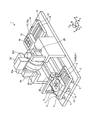
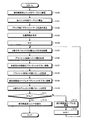
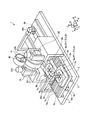
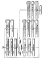
図1は、第1の実施形態に係る印刷装置1の構成の一例を示す斜視図である。図1に示す印刷装置1は、ローラ胴20および本体2を備える。本体2には、図1のX軸方向に延伸する複数のリニアガイド3が設けられている。なお、以下の各図では、必要に応じてX軸、Y軸、およびZ軸が記載されるが、各図におけるX軸、Y軸、およびZ軸は、図1に示したX軸、Y軸、およびZ軸にそれぞれ対応している。
[Configuration of Printing Apparatus 1]
FIG. 1 is a perspective view illustrating an example of a configuration of a
リニアガイド3上には、基台5が設けられており、基台5は、基台5の下部に設けられたリニアモータ4によってリニアガイド3に沿ってX軸方向に移動する。基台5の上面には、図1のY軸方向に延伸する複数のリニアガイド6が設けられ、リニアガイド6上には、被印刷基板テーブル8が設けられている。被印刷基板テーブル8は、被印刷基板テーブル8の下部に設けられたリニアモータ7によってリニアガイド6に沿ってY軸方向に移動する。被印刷基板テーブル8上には、複数の被印刷基板ブロック9が配置された被印刷基板ユニット10が載置される。なお、以下では、被印刷基板ブロック9を、単にブロック9と記載する。被印刷基板ユニット10は、複数のブロック9を樹脂等で固め、端子面を露出させたものである。ブロック9は被印刷物の一例であり、被印刷基板ユニット10は被印刷基材の一例である。
A
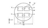
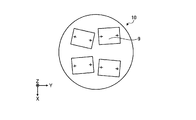
ここで、被印刷基板ユニット10内には、例えば図2に示すように、複数のブロック9が配置されている。図2は、被印刷基板ユニット10内のブロック9の配置の一例を示す図である。それぞれのブロック9には、アライメントマーク90が設けられている。被印刷基板ユニット10内には、Y軸方向に複数のブロック9が配置されている。Y軸方向において、それぞれのブロック9の幅をL1、隣接するブロック9間の距離をd1、被印刷基板ユニット10の幅をL0と定義する。本実施形態において、被印刷基板ユニット10には、例えば図2に示すように、Y軸方向に2つのブロック9が配置されている。即ち、Y軸方向に配置されているブロック9の数の最大値nは2である。リニアモータ7は、少なくとも(L1+d1)×(n−1)の長さ分、被印刷基板テーブル8をY軸方向に移動させることができる。本実施形態では、ブロック9の数の最大値nの値が2であるため、リニアモータ7は、少なくともL1+d1の長さ分、被印刷基板テーブル8をY軸方向に移動させることができる。なお、リニアモータ7は、被印刷基板ユニット10の幅L0の長さ分、被印刷基板テーブル8をY軸方向に移動させてもよい。
Here, as shown in FIG. 2, for example, a plurality of
被印刷基板ユニット10内に配置されたそれぞれのブロック9は、平板状のフィルム基板、ガラス基板、または複数のデバイスが配置されたFOWLP(Fan−Out Wafer Level Package)等の被印刷物である。それぞれのブロック9には、ローラ胴20の外周に巻き回されたブランケット21の表面に形成された印刷パターンのインクが転写(印刷)される。
Each
被印刷基板テーブル8には、被印刷基板テーブル8上に載置された被印刷基板ユニット10を固定する保持部80が組み込まれている。保持部80は、真空チャックや機械式固定法等により、被印刷基板ユニット10を被印刷基板テーブル8上に固定する。また、被印刷基板テーブル8には、被印刷基板テーブル8上に載置された被印刷基板ユニット10を図1に示すX、Y、およびZ軸の方向、並びに、X軸回りの回転Ψ、Y軸回りの回転Υ、およびZ軸回りの回転Θの方向へそれぞれ移動させることが可能な6軸駆動機構81が組み込まれている。6軸駆動機構81により、6軸それぞれにおいて、ローラ胴20に対する各ブロック9のずれを微調整することができる。6軸駆動機構81の移動座標系は、被印刷基板テーブル8の座標系に一致するように予め調整されている。被印刷基板テーブル8は、移動部の一例である。また、6軸駆動機構81において、被印刷基板ユニット10をX軸方向およびY軸方向に移動させる機構は、第1の移動部の一例である。また、6軸駆動機構81において、被印刷基板ユニット10をZ軸回りの回転Θの方向に回転させる機構は、第2の移動部の一例である。また、6軸駆動機構81において、被印刷基板ユニット10をX軸回りの回転Ψの方向およびY軸回りの回転Υの方向にそれぞれ回転させる機構は、第3の移動部の一例である。
The printed substrate table 8 includes a holding
また、リニアガイド3上には、基台13が設けられており、基台13は、基台13の下部に設けられたリニアモータ14によってリニアガイド3に沿ってX軸方向に移動する。基台13には、Y軸方向に延伸する複数のリニアガイド15が設けられ、リニアガイド15上には、版テーブル17が設けられている。版テーブル17は、版テーブル17の下部に設けられたリニアモータ16によってリニアガイド15に沿ってY軸方向に移動する。版テーブル17上には、複数の印刷版18が配置された版ユニット19が載置される。版ユニット19は、版テーブル17に設けられた保持部170によって、版テーブル17上に固定される。保持部170は、真空チャックや機械式固定法等により、版ユニット19を版テーブル17上に固定する。版ユニット19は、除去基材の一例であり、それぞれの印刷版18は、除去パターンの一例である。なお、版テーブル17にも、版テーブル17上に載置された版ユニット19を図1に示すX、Y、およびZ軸の方向、並びに、X軸回りの回転Ψ、Y軸回りの回転Υ、およびZ軸回りの回転Θの方向へそれぞれ移動させることが可能な6軸駆動機構が組み込まれていてもよい。リニアモータ14およびリニアモータ16は、除去基材移動部の一例である。
Further, a
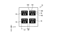
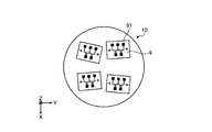
図3は、版ユニット19内の印刷版18の配置の一例を示す図である。版ユニット19内には、例えば図3に示すように、平板状の複数の印刷版18が配置されている。それぞれの版ユニット19には、印刷パターンに応じた凹部180(図3において白抜きで示された部分)と、余分なインクを吸着除去するための凸部181(図3において黒く塗りつぶされた部分)と、位置合わせのためのアライメントマーク182とが含まれる。図3に例示した版ユニット19には、Y軸方向における幅がL2である4つの印刷版18が、Y軸方向においてd2の間隔で配置されている。
FIG. 3 is a diagram showing an example of the arrangement of the
なお、版ユニット19に含まれる印刷版18の数は、3以下であってもよく、5以上であってもよい。また、版ユニット19に含まれる印刷版18の数は、被印刷基板ユニット10に含まれるブロック9の数と同じかそれ以上であることが好ましい。これにより、被印刷基板ユニット10の洗浄の頻度を少なくすることができる。また、図3に例示した版ユニット19には、複数の印刷版18がX軸方向およびY軸方向に配列されているが、複数の印刷版18は、X軸方向またはY軸方向に1列に配列されてもよい。
The number of
ローラ胴20は、外周に、例えばシリコーン等で形成された撥水性を有するブランケット21が巻き回されたブランケット胴である。ブランケット21は、印刷処理において、版ユニット19内の印刷版18および被印刷基板ユニット10内のブロック9に順次押し当てられる。このため、ブランケット21はクッション性を有する材料で形成される。ブランケット21は、例えば図1に示すZ軸方向において、印刷版18およびブロック9に押し当てられる。ブランケット21が印刷版18およびブロック9に押し当てられる方向は、押圧方向の一例である。ブランケット21の表面のうち、インク膜が塗布される領域は、転写領域の一例である。
The
本実施形態において、ローラ胴20の回転軸方向(即ち、図1のY軸方向)におけるブランケット21の幅は、被印刷基板ユニット10内に配置された各ブロック9のY軸方向における幅、および、版ユニット19内に配置された各印刷版18のY軸方向における幅に対応している。例えば、ローラ胴20の回転軸方向におけるブランケット21の幅は、1つのブロック9に所定の印刷パターンを印刷するために必要となる最小の領域に対応した長さである。
In the present embodiment, the width of the
ブランケット21のY軸方向における幅が、1つのブロック9に所定の印刷パターンを印刷するために必要となる最小の領域の幅に対応した長さであることにより、ブランケット21およびローラ胴20を小型化することができる。これにより、ローラ胴20の軽量化が可能となり、ローラ胴20と被印刷基板テーブル8との間の共振周波数、および、ローラ胴20と版テーブル17との間の共振周波数を上げることができる。これにより、印刷装置1の外部からの振動による共振が起りにくくなり、印刷時の印刷パターンのぶれが抑えられる。これにより、それぞれのブロック9に高い精度で所定のパターンを印刷することができる。なお、本実施形態の印刷装置1では、ブロック9毎に印刷を行うため、ブランケット21の周方向の長さも短くすることができる。これにより、ブランケット21およびローラ胴20をさらに小型化することができる。
Since the width of the
ここで、被印刷基板ユニット10内には、例えば図2に示したように、Y軸方向に複数のブロック9が配置されている。被印刷基板ユニット10をY軸方向に移動させるリニアモータ7は、少なくとも(L1+d1)×(n−1)の長さ分、被印刷基板テーブル8を移動させることができる。これにより、リニアモータ7は、Y軸方向に1ブロック分の幅(即ち、L1の幅)を有するブランケット21の下方の位置に、Y軸方向に複数配置されたブロック9のそれぞれを移動させることができる。これにより、ブランケット21は、ブロック9毎に、ブロック9に印刷パターンを印刷することができる。
Here, in the
ローラ胴20の回転軸の両端は、ブラケット22に固定された軸受で支持される。ブラケット22全体は上下機構23aおよび23bにより上下方向(即ち、図1のZ軸方向)に移動可能である。上下機構23aおよび23bは、駆動モータの回転をネジにより上下方向の直線運動に変換して、ローラ胴20の回転軸の両端を、それぞれ独立に上下させることができる。ローラ胴20の一端には、ブラケット22に固定された回転駆動用の回転機構24が連結されている。Z軸方向において、印刷版18およびブロック9に対するローラ胴20の位置の微調整は、上下機構23aおよび23bによって行われる。ローラ胴20の上部には、インクをブランケット21に塗布するコーター25が設けられている。上下機構23aおよび23b、ならびに、回転機構24は、印刷部の一例である。
Both ends of the rotation shaft of the
マーク検出器26は、被印刷基板テーブル8上に載置された被印刷基板ユニット10内の各ブロック9に設けられたアライメントマークを撮影し、撮影されたアライメントマークの位置および向きに基づいて、ローラ胴20に対する各ブロック9の位置および向きを示す位置情報を検出する。そして、マーク検出器26は、検出した位置情報を、印刷装置1を制御する制御部に接続された記憶装置内に格納する。マーク検出器26は、検出部の一例である。被印刷基板テーブル8は、6軸駆動機構81により、記憶装置内に格納された位置情報に基づいて、ブロック9毎に、ローラ胴20とブロック9とが所定の位置関係となるように、ブロック9の位置および向きを微調整する。具体的には、被印刷基板テーブル8の6軸駆動機構81は、記憶装置内に格納された位置情報に基づいて、印刷時に、ローラ胴20のブランケット21上に形成された印刷パターンに含まれるアライメントマークと、ブロック9に設けられたアライメントマークとが同じ向きで重なるように、ブロック9毎にブロック9の位置および向きを微調整する。なお、本実施例にいて、向きには、傾きが含まれる。
The
印刷装置1の各部は、図示しない制御装置によりその動作が統括的に制御される。制御装置は、CPU(Central Processing Unit)等のプロセッサを有する。制御装置には、記憶装置およびキーボードやディスプレイ等のユーザインターフェイスが接続されている。
The operation of each unit of the
記憶装置には、印刷装置1で実行される各種処理を制御装置が実現するための制御プログラムや、ブロック9毎にマーク検出器26によって検出された位置情報等のデータが格納される。制御装置は、記憶装置内に格納された制御プログラムを読み出して実行することにより、印刷装置1に、被印刷基板ユニット10内の各ブロック9に所定の印刷パターンを印刷させる。
The storage device stores a control program for realizing various processes executed by the
[印刷装置1の動作]
次に、本実施形態における印刷装置1の動作について、図4および図5を参照しながら説明する。図4は、印刷装置1の動作の一例を説明するための概略断面図である。図5は、第1の実施形態に係る印刷装置1の動作の一例を示すフローチャートである。
[Operation of Printing Apparatus 1]
Next, the operation of the
まず、リニアモータ4およびリニアモータ7は、被印刷基板テーブル8を所定の初期位置に移動させる。そして、図示しないロボットアームにより被印刷基板テーブル8上に被印刷基板ユニット10が載置され、固定される(S100)。また、リニアモータ14およびリニアモータ16は、版テーブル17を所定の初期位置に移動させる。そして、図示しないロボットアームにより版テーブル17上に版ユニット19が載置され、固定される(S101)。
First, the linear motor 4 and the
次に、リニアモータ4およびリニアモータ7は、被印刷基板テーブル8をマーク検出器26の下方に移動させる。マーク検出器26は、被印刷基板ユニット10内のブロック9毎に、ブロック9に設けられたアライメントマーク90を読み取る(S102)。そして、マーク検出器26は、読み取ったアライメントマーク90の位置および向きに基づいて、ローラ胴20に対する各ブロックの位置および向きを示す位置情報を検出する。マーク検出器26によって検出された位置情報は、ブロック毎に記憶装置に保存される(S103)。
Next, the linear motor 4 and the
次に、ブロック数をカウントするための変数Nが1に初期化される(S104)。そして、被印刷基板テーブル8の6軸駆動機構81は、被印刷基板ユニット10内のN番目のブロックについて、記憶装置内に格納された位置情報に基づいて、該ブロックがブランケット21の下方に位置した時に、該ブロックとローラ胴20とが所定の位置関係となるようにブロックの位置および向きを微調整する(S105)。
Next, a variable N for counting the number of blocks is initialized to 1 (S104). Then, the 6-axis drive mechanism 81 of the printed substrate table 8 positions the N-th block in the printed
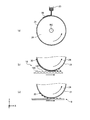
次に、上下機構23aおよび23bは、ローラ胴20を上昇させる。そして、回転機構24は、回転軸RCを中心としてローラ胴20を回転させ、ローラ胴20の回転位置を所定の初期位置に戻す。そして、図示しない移動機構により、コーター25のノズルの先端とブランケット21の表面との距離が所定の距離になるまで、コーター25がブランケット21に近づけられる。そして、例えば図4(a)に示すように、回転機構24がローラ胴20を初期位置から回転させると共に、コーター25からインクが吐出されることにより、ブランケット21の表面の所定の領域に一定の膜厚のインク膜30が形成される(S106)。ブランケット21の表面の所定の領域にインク膜30が形成された後、コーター25は、所定の退避位置まで退避し、回転機構24は、ローラ胴20を回転させ、ローラ胴20の回転位置を所定の位置まで戻す。
Next, the
次に、上下機構23aおよび23bは、ローラ胴20を印刷位置まで下降させる。また、リニアモータ14およびリニアモータ16は、版ユニット19内の未使用の1つの印刷版18がブランケット21の下方に位置するように、版テーブル17を移動させる(S107)。
Next, the
次に、回転機構24は、リニアモータ14によるX軸方向への版テーブル17の移動と連動してローラ胴20を回転させる。回転によるローラ胴20の最外周の速度は、X軸方向への版テーブル17の移動速度と一致している。このため、例えば図4(b)に示すように、版テーブル17上の印刷版18は、印刷版18の表面において、ブランケット21とほぼ直線状に接触する領域内の凸部181によって、ブランケット21の表面に形成されたインク膜30からインクをはぎ取りながらX軸の方向に移動する。この結果、撥水性のブランケット21の表面には、印刷版18の凹部180に対応する領域にインク膜30が残存した印刷パターンが形成される(S108)。
Next, the
次に、上下機構23aおよび23bは、ローラ胴20を所定の退避位置まで上昇させる。また、回転機構24は、ローラ胴20を回転させ、ローラ胴20の回転位置を所定の位置まで戻す。また、リニアモータ14は、版テーブル17を所定の退避位置まで移動させる。
Next, the
次に上下機構23aおよび23bは、ローラ胴20を印刷位置まで下降させる。また、リニアモータ4およびリニアモータ7は、被印刷基板ユニット10内のN番目のブロックがブランケット21の下方に位置するように、被印刷基板テーブル8を移動させる(S109)。
Next, the
次に、回転機構24は、リニアモータ4によるX軸方向への被印刷基板テーブル8の移動と連動してローラ胴20を回転させる。回転によるローラ胴20の最外周の速度は、X軸方向への被印刷基板テーブル8の移動速度と一致している。このため、例えば図4(c)に示すように、インク膜30の残存によりブランケット21の表面に形成された印刷パターンが、N番目のブロック9上に転写される(S110)。
Next, the
次に、印刷装置1は、変数Nが、被印刷基板ユニット10内に配置されたブロック9の数を示す所定値N0に達したか否かを判定する(S111)。変数Nが所定値N0に達していない場合(S111:No)、印刷装置1は、リニアモータ4により被印刷基板テーブル8を所定の退避位置まで退避させる(S112)。そして、印刷装置1は、変数Nを1増加させる(S113)。そして、被印刷基板テーブル8の6軸駆動機構81は、再びステップS105に示した処理を実行する。
Next, the
一方、変数Nが所定値N0に達した場合(S111:Yes)、リニアモータ4は、被印刷基板テーブル8を初期位置まで移動させる。そして、図示しないロボットアームにより、被印刷基板ユニット10が被印刷基板テーブル8上から搬出される(S114)。そして、印刷装置1は、本フローチャートに示した動作を終了する。
On the other hand, if the variable N has reached the predetermined value N 0 (S111: Yes), the linear motor 4 moves the substrate to be printed table 8 to the initial position. Then, the
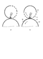
ここで、複数のブロック9が樹脂等で固められて被印刷基板ユニット10が形成される場合、被印刷基板ユニット10の形成過程では、それぞれのブロック9を配置する際の位置ずれや、樹脂の流動に伴うブロック9の位置ずれ等が起こる。これにより、樹脂等が硬化した後の被印刷基板ユニット10内の各ブロック9の位置や向きは、例えば図6に示すように、位置や向きが設計値からずれる場合がある。位置や向きが設計値からずれた複数のブロック9に対して、設計値通りのブロック9の配置を想定した印刷パターンを用いて複数のブロック9に一括印刷を行うと、各ブロック9に対して所望の位置からずれた印刷パターンが印刷されることになる。印刷により形成されるパターンの微細化が進むと、印刷パターンのずれが無視できなくなる。
Here, when the plurality of
これに対し、本実施形態の印刷装置1では、被印刷基板ユニット10内のブロック9毎に、ブランケット21とブロック9とが所定の位置関係になるように微調整した後に、ブランケット21に形成された印刷パターンをブロック9に印刷する。これにより、例えば図7に示すように、位置や向きが設計値からずれたブロック9に対しても、ブロック9毎に高い精度で印刷パターン91を印刷することができる。従って、本実施形態の印刷装置1は、より微細なパターンをより高い精度で各ブロック9に印刷することができる。なお、各ブロック9には、複数の同一または異なる印刷パターンのインクが重ねて印刷されてもよい。これにより、各ブロック9に対して、所定の厚さの構造物を高い精度で形成することができる。
On the other hand, in the
<第1の実施形態の変形例>
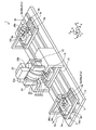
次に、第1の実施形態に係る印刷装置1の変形例について説明する。図8は、第1の実施形態に係る印刷装置1の変形例を示す斜視図である。なお、以下に説明する点を除き、図8において図1と同じ符号を付した構成は、図1を用いて説明した構成と同一または同様の機能を有するため、詳細な説明を省略する。
<Modification of First Embodiment>
Next, a modified example of the
本変形例に係る印刷装置1では、2台の基台(5aおよび5b)のそれぞれに被印刷基板テーブル(8aおよび8b)を設け、それぞれの被印刷基板テーブルに複数の被印刷基板(9aおよび9b)が配置された被印刷基板ユニット(10aおよび10b)が載置される。そして、2つの被印刷基板ユニット10aおよび10bのうち、一方の被印刷基板ユニット内のブロックに対して印刷処理が行われている間に、他方の被印刷基板ユニットのブロックについて位置情報の読み取りが行われる。印刷処理とは、例えば、ブランケット21表面にインク膜を形成する処理、ブランケット21表面のインク膜を印刷パターンに成形する処理、およびブランケット21表面の印刷パターンをブロックに転写する処理が、被印刷基板ユニット10内の各ブロックについて繰り返し実行される処理である。
In the
本変形例の印刷装置1には、基台5aおよび基台5bが設けられており、基台13は、X軸方向において、基台5aと基台5bの間に配置されている。基台5a上には、被印刷基板テーブル8aが設けられており、基台5b上には、被印刷基板テーブル8bが設けられている。被印刷基板テーブル8a上には、複数のブロック9aが配置された被印刷基板ユニット10aが載置され、被印刷基板テーブル8b上には、複数のブロック9bが配置された被印刷基板ユニット10bが載置される。また、本変形例の印刷装置1には、マーク検出器26aおよび26bが設けられている。被印刷基板ユニット10a内の各ブロック9aの位置情報は、マーク検出器26aによって読み取られ、被印刷基板ユニット10b内の各ブロック9bの位置情報は、マーク検出器26bによって読み取られる。
The
本変形例では、被印刷基板テーブル8a上のブロック9aに対して印刷処理が行われている間に、基台13および被印刷基板テーブル8bを退避でき、被印刷基板テーブル8b上のブロック9bに対して印刷処理が行われている間に、基台13および被印刷基板テーブル8aを退避できるように、本体2が、実施形態1に係る印刷装置1の本体2よりも長く構成されている。
In this modification, the
[印刷装置1の動作]
次に、図8のように構成された印刷装置1の動作について説明する。まず、リニアモータ4bにより基台5bが退避位置に移動する。そして、第1の実施形態における印刷動作と同様に、被印刷基板ユニット10a内のブロック9a毎に、ローラ胴20の下方の位置に移動した印刷版18によるブランケット21への印刷パターンの形成と、ローラ胴20の下方の位置に移動した被印刷基板ユニット10a内のブロック9aに対する印刷パターンの転写とが交互に実行される。
[Operation of Printing Apparatus 1]
Next, the operation of the
一方、リニアモータ4bにより退避スペースに移動した基台5b上の被印刷基板テーブル8bには、図示しないロボットアームにより被印刷基板ユニット10bが載置され、固定される。そして、被印刷基板ユニット10a内の各ブロック9aに対して印刷パターンの転写が行われる間に、マーク検出器26bにより被印刷基板ユニット10b内の各ブロック9bの位置情報の読み取りが行われる。マーク検出器26bによって読み取られた被印刷基板ユニット10b内の各ブロック9bの位置情報は、記憶装置内に保存される。
On the other hand, the printed
そして、被印刷基板ユニット10a内の各ブロック9aに対して印刷パターンの転写が終了した場合、リニアモータ4aにより基台5aが初期位置に移動し、図示しないロボットアームにより、被印刷基板ユニット10aが被印刷基板テーブル8aから搬出され、別な被印刷基板ユニット10aが被印刷基板テーブル8a上に載置され固定される。また、被印刷基板ユニット10bについては、第1の実施形態における印刷動作と同様に、被印刷基板ユニット10b内のブロック9b毎に、ローラ胴20の下方の位置に移動した印刷版18によるブランケット21への印刷パターンの形成と、ローラ胴20の下方の位置に移動した被印刷基板ユニット10b内のブロック9bに対する印刷パターンの転写とが交互に実行される。
Then, when the transfer of the printing pattern to each
このように、2台の被印刷基板テーブル8aおよび8bと、1台の版テーブル17とを用いて各被印刷基板ユニット内の被印刷基板に印刷を行うことにより、各被印刷基板に対する位置情報の検出と印刷パターンの印刷とを並行して実行することができる。これにより、本変形例に係る印刷装置1は、各被印刷基板に対する印刷パターンの印刷を高い精度で実行することができると共に、印刷処理のスループットを向上させることができる。
As described above, by performing printing on the printing substrate in each printing substrate unit using the two printing substrate tables 8a and 8b and the one plate table 17, positional information on each printing substrate. Detection and printing of the print pattern can be executed in parallel. As a result, the
<第2の実施形態>
次に、第2の実施形態に係る印刷装置1について説明する。本実施形態に係る印刷装置1では、ローラ胴20のブランケット21表面へのインク供給がロータリースクリーン法により行われる。これにより、反転印刷法で印刷毎に必要となる印刷版の洗浄やブランケット21の清掃等の処理が不要、あるいは、数十回から数百回の印刷毎の処理で済む。そのため、印刷装置1の稼働率を高めることができる。また、印刷版の洗浄やブランケット21の清掃等の処理の頻度を少なくすることができるため、廃棄されるインクの量を低減することができ、インクの使用効率を高めることができる。
<Second Embodiment>
Next, the
図9は、第2の実施形態に係る印刷装置1の構成の一例を示す斜視図である。なお、以下に説明する点を除き、図9において図1と同じ符号を付した構成は、図1を用いて説明した構成と同一または同様の機能を有するため、詳細な説明を省略する。
FIG. 9 is a perspective view illustrating an example of the configuration of the
ローラ胴20の上部には、略円筒状のステンシル型のスクリーン版40が設けられている。スクリーン版40は、印刷パターンに対応する領域が開口しており、該開口を介して、スクリーン版40内に供給されたインクがスキージ41により押し出される。これにより、ブランケット21の表面に、該開口に対応する印刷パターンの形状でインク膜30が形成される。スクリーン版40は、印刷パターン形成部の一例である。Y軸方向におけるスクリーン版40の幅は、Y軸方向におけるブランケット21の幅およびブロック9の幅(即ち、Y軸方向における1ブロックの幅)に対応している。例えば、Y軸方向におけるスクリーン版40の幅は、Y軸方向におけるブランケット21の幅およびブロック9の幅(即ち、Y軸方向における1ブロックの幅)と同一の長さである。
A substantially cylindrical stencil
[印刷装置1の動作]
次に、図9のように構成された印刷装置1の動作について、図10を参照しながら説明する。図10は、第2の実施形態における印刷パターンの形成過程の一例を説明するための概略図である。まず、被印刷基板テーブル8が所定の初期位置に移動され、図示しないロボットアームにより被印刷基板テーブル8上に被印刷基板ユニット10が載置され、固定される。そして、被印刷基板テーブル8がマーク検出器26の下方に移動され、マーク検出器26によって、被印刷基板ユニット10内のブロック9毎に、アライメントマーク90が読み取られる。そして、読み取られたアライメントマーク90に基づいて検出された位置情報は、ブロック毎に記憶装置に保存される。
[Operation of Printing Apparatus 1]
Next, the operation of the
次に、被印刷基板テーブル8の6軸駆動機構81は、被印刷基板ユニット10内の1つのブロックについて、記憶装置内に格納された位置情報に基づいて、該ブロックがブランケット21の下方に位置した時に、該ブロックとローラ胴20とが所定の位置関係となるようにブロックの位置および向きを微調整する。
Next, the 6-axis drive mechanism 81 of the substrate table 8 to be printed is positioned below the
次に、上下機構23aおよび23bは、ローラ胴20を上昇させる。そして、回転機構24は、回転軸RCを中心としてローラ胴20を回転させ、ローラ胴20の回転位置を所定の初期位置に戻す。そして、上下機構23aおよび23bは、例えば図10(a)に示すように、スクリーン版40とブランケット21の表面との距離が所定の距離になるように、ローラ胴20を上昇させる。そして、回転機構24がローラ胴20を初期位置から回転させると共に、ローラ胴20の回転に合わせてスクリーン版40が回転する。これにより、例えば図10(b)に示すように、スクリーン版40内のインクが、印刷パターンに応じた開口からスキージ41により押し出される。これにより、ブランケット21の表面の所定の領域に印刷パターンに対応する一定の膜厚のインク膜30が形成される。ブランケット21の表面の所定の領域に印刷パターンに対応するインク膜30が形成された後、上下機構23aおよび23bは、ローラ胴20を所定の待機位置まで下降させる。そして、回転機構24は、ローラ胴20を回転させ、ローラ胴20の回転位置を所定の位置まで戻す。
Next, the
次に、上下機構23aおよび23bは、ローラ胴20を印刷位置まで下降させる。また、リニアモータ4およびリニアモータ7は、被印刷基板ユニット10内のブロックの中で、位置および向きの微調整が行われたブロックがブランケット21の下方に位置するように、被印刷基板テーブル8を移動させる。
Next, the
次に、回転機構24は、リニアモータ4によるX軸方向への被印刷基板テーブル8の移動と連動してローラ胴20を回転させる。回転によるローラ胴20の最外周の速度と、X軸方向への被印刷基板テーブル8の移動速度とは一致しているため、例えば図4(c)に示したように、インク膜30の残存によりブランケット21の表面に形成された印刷パターンが、ブロック9上に転写される。
Next, the
以上の処理を、被印刷基板ユニット10内のブロック9毎に実行する。これにより、本実施形態の印刷装置1は、被印刷基板ユニット10上の各ブロック9の位置および向きが設計値通りの位置および向きからずれている場合であっても、各ブロック9に対して高い精度で印刷パターンを印刷することができる。さらに、本実施形態の印刷装置1は、ブランケット21表面への印刷パターンの形成を、ロータリースクリーン法により実行する。これにより、反転印刷法で印刷毎に必要となる印刷版の洗浄やブランケット21の清掃等の処理が不要、あるいは、数十回から数百回の印刷毎の処理で済む。そのため、印刷装置1の稼働率を高めることができる。また、印刷版の洗浄やブランケット21の清掃等の処理の頻度を少なくすることができるため、排気されるインクの量を低減することができ、インクの使用効率を高めることができる。
The above processing is executed for each
<第2の実施形態の変形例>
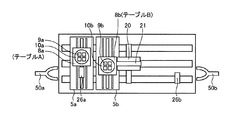
次に、第2の実施形態に係る印刷装置1の変形例について説明する。図11は、第2の実施形態に係る印刷装置1の変形例を示す斜視図である。図12は、第2の実施形態に係る印刷装置1の変形例を示す概略上面図である。図12は、印刷装置1のうち、ブラケット22、上下機構23a、上下機構23b、回転機構24、およびスクリーン版40等を除いた部分の上面を示している。なお、以下に説明する点を除き、図11および図12において図1、図8、または図9と同じ符号を付した構成は、図1、図8、または図9を用いて説明した構成と同一または同様の機能を有するため、詳細な説明を省略する。
<Modification of Second Embodiment>
Next, a modified example of the
本変形例に係る印刷装置1では、2台の基台(5aおよび5b)のそれぞれに被印刷基板テーブル(8aおよび8b)を設け、それぞれの被印刷基板テーブルに複数の被印刷基板(9aおよび9b)が配置された被印刷基板ユニット(10aおよび10b)が載置される。そして、2つの被印刷基板ユニット10aおよび10bのうち、一方の被印刷基板ユニット内のブロックに対して印刷処理が行われている間に、他方の被印刷基板ユニットのブロックについて位置情報の読み取りが行われる。なお、以下では、被印刷基板テーブル8aをテーブルAと記載し、被印刷基板テーブル8bをテーブルBと記載する場合がある。
In the
[印刷装置1の動作]
次に、本実施形態に係る印刷装置1の変形例の動作について、図13および図14を参照しながら説明する。図13および図14は、第2の実施形態に係る印刷装置1の変形例の動作の一例を示すフローチャートである。
[Operation of Printing Apparatus 1]
Next, the operation of a modified example of the
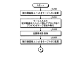
まず、リニアモータ4aおよびリニアモータ7aは、テーブルAを所定の初期位置に移動させる。そして、図12に示したロボットアーム50aによりテーブルA上に被印刷基板ユニット10aが載置され、固定される(S200)。
First, the
次に、リニアモータ4aおよびリニアモータ7aは、テーブルAをマーク検出器26aの下方に移動させる。マーク検出器26aは、被印刷基板ユニット10a内のブロック9a毎に、ブロック9aに設けられたアライメントマーク90を読み取る(S201)。そして、マーク検出器26aは、読み取ったアライメントマーク90の位置および向きに基づいて、ローラ胴20に対する各ブロックの位置および向きを示す位置情報を検出する。マーク検出器26aによって検出された位置情報は、ブロック毎に記憶装置に保存される(S202)。
Next, the
次に、リニアモータ4bおよびリニアモータ7bは、テーブルBを所定の初期位置に移動させる。そして、図12に示したロボットアーム50bによりテーブルB上に被印刷基板ユニット10bが載置され、固定される(S203)。
Next, the
次に、テーブルA上の被印刷基板ユニット10aに対して印刷処理が実行される(S204)。ステップS204では、被印刷基板ユニット10a内の各ブロックについて、以下の印刷処理が実行される。即ち、テーブルAの6軸駆動機構81aは、被印刷基板ユニット10a内の各ブロックについて、記憶装置内に格納された位置情報に基づいて、該ブロックがブランケット21の下方に位置した時に、該ブロックとローラ胴20とが所定の位置関係となるようにブロックの位置および向きを微調整する。次に、上下機構23aおよび23bは、スクリーン版40とブランケット21の表面との距離が所定の距離になるように、ローラ胴20を上昇させる。そして、回転機構24がローラ胴20を初期位置から回転させると共に、ローラ胴20の回転に合わせてスクリーン版40が回転する。これにより、スクリーン版40内のインクが、印刷パターンに応じた開口からスキージ41により押し出され、ブランケット21の表面の所定の領域に印刷パターンに対応する一定の膜厚のインク膜30が形成される。そして、上下機構23aおよび23bは、ローラ胴20を所定の待機位置まで下降させ、回転機構24は、ローラ胴20を回転させ、ローラ胴20の回転位置を所定の位置まで戻す。そして、上下機構23aおよび23bは、ローラ胴20を印刷位置まで下降させる。また、リニアモータ4aおよびリニアモータ7aは、被印刷基板ユニット10a内のブロックの中で、位置および向きの微調整が行われたブロックがブランケット21の下方に位置するように、テーブルAを移動させる。そして、回転機構24は、リニアモータ4aによるX軸方向へのテーブルAの移動と連動してローラ胴20を回転させる。これにより、ブランケット21の表面に形成された印刷パターンが、被印刷基板ユニット10a内のブロック上に転写される。
Next, a printing process is performed on the
ステップS204の処理が終了した後、リニアモータ4aおよびリニアモータ7aは、テーブルAを所定の初期位置に移動させる(S205)。そして、ロボットアーム50aにより被印刷基板ユニット10aがテーブルAから搬出される(S206)。
After the process of step S204 is completed, the
一方、ステップS204の実行と並行して、リニアモータ4bおよびリニアモータ7bは、テーブルBをマーク検出器26bの下方に移動させる。マーク検出器26bは、被印刷基板ユニット10b内のブロック9b毎に、ブロック9bに設けられたアライメントマーク90を読み取る(S207)。そして、マーク検出器26bは、読み取ったアライメントマーク90の位置および向きに基づいて、ローラ胴20に対する各ブロックの位置および向きを示す位置情報を検出する。マーク検出器26bによって検出された位置情報は、ブロック毎に記憶装置に保存される(S208)。
On the other hand, in parallel with the execution of step S204, the
次に、終了条件が満たされたか否かが判定される(S209)。終了条件とは、例えば所定数の被印刷基板ユニット10aおよび10bへの印刷処理が実行されたという条件である。所定条件が満たされていない場合(S209:No)、ロボットアーム50aによりテーブルA上に別の被印刷基板ユニット10aが載置され、固定される(S210)。そして、リニアモータ4aおよびリニアモータ7aにより、テーブルAがマーク検出器26aの下方に移動され、マーク検出器26aにより、被印刷基板ユニット10a内のブロック毎にアライメントマーク90が読み取られ、位置情報が検出される(S211)。そして、マーク検出器26aによって検出された位置情報は、ブロック毎に記憶装置に保存される(S212)。そして、後述するステップS214が実行された後に、再びステップS204に示した処理が実行される。
Next, it is determined whether an end condition is satisfied (S209). The termination condition is, for example, a condition that printing processing for a predetermined number of
一方、ステップS210〜S212に示した処理の実行と並行して、テーブルB上の被印刷基板ユニット10bに対して印刷処理が実行される(S213)。ステップS213では、被印刷基板ユニット10b内の各ブロックについて、以下の印刷処理が実行される。即ち、テーブルBの6軸駆動機構81bは、被印刷基板ユニット10b内の各ブロックについて、記憶装置内に格納された位置情報に基づいて、該ブロックがブランケット21の下方に位置した時に、該ブロックとローラ胴20とが所定の位置関係となるようにブロックの位置および向きを微調整する。次に、上下機構23aおよび23bは、スクリーン版40とブランケット21の表面との距離が所定の距離になるように、ローラ胴20を上昇させる。そして、回転機構24がローラ胴20を初期位置から回転させると共に、ローラ胴20の回転に合わせてスクリーン版40が回転する。これにより、スクリーン版40内のインクが、印刷パターンに応じた開口からスキージ41により押し出され、ブランケット21の表面の所定の領域に印刷パターンに対応する一定の膜厚のインク膜30が形成される。そして、上下機構23aおよび23bは、ローラ胴20を所定の待機位置まで下降させ、回転機構24は、ローラ胴20を回転させ、ローラ胴20の回転位置を所定の位置まで戻す。そして、上下機構23aおよび23bは、ローラ胴20を印刷位置まで下降させる。また、リニアモータ4bおよびリニアモータ7bは、被印刷基板ユニット10b内のブロックの中で、位置および向きの微調整が行われたブロックがブランケット21の下方に位置するように、テーブルBを移動させる。そして、回転機構24は、リニアモータ4bによるX軸方向へのテーブルBの移動と連動してローラ胴20を回転させる。これにより、ブランケット21の表面に形成された印刷パターンが、被印刷基板ユニット10b内のブロック上に転写される。
On the other hand, in parallel with the execution of the processes shown in steps S210 to S212, the printing process is executed for the
ステップS213の処理が終了した後、リニアモータ4bおよびリニアモータ7bは、テーブルBを所定の初期位置に移動させる(S214)。そして、ロボットアーム50bにより被印刷基板ユニット10bがテーブルBから搬出される(S215)。そして、ロボットアーム50bによりテーブルB上に別の被印刷基板ユニット10bが載置され、固定される(S216)。そして、再びステップS207に示した処理が実行される。
After the process of step S213 is completed, the
一方、終了条件が満たされた場合(S209:Yes)、テーブルB上の被印刷基板ユニット10bに対して印刷処理が実行される(S217)。ステップS217において実行される印刷処理は、ステップS213において実行される印刷処理と同様であるため、説明を省略する。ステップS217の印刷処理が終了した後、リニアモータ4bおよびリニアモータ7bは、テーブルBを所定の初期位置に移動させる(S218)。そして、ロボットアーム50bにより被印刷基板ユニット10bがテーブルBから搬出される(S219)。そして、印刷装置1は、本フローチャートに示した動作を終了する。
On the other hand, when the termination condition is satisfied (S209: Yes), the printing process is executed on the
これにより、本変形例の印刷装置1は、被印刷基板ユニット10上の各ブロック9の位置および向きが設計値通りの位置および向きからずれている場合であっても、各ブロック9に対して高い精度で印刷パターンを印刷することができる。さらに、本変形例の印刷装置1では、ロータリースクリーン法によりブランケット21の表面に印刷パターンが形成されるため、反転印刷法で印刷毎に必要となる印刷版の洗浄やブランケット21の清掃等の処理が不要、あるいは、数十回から数百回の印刷毎の処理で済む。そのため、印刷装置1の稼働率を高めることができる。また、印刷版の洗浄やブランケット21の清掃等の処理の頻度を少なくすることができるため、排気されるインクの量を低減することができ、インクの使用効率を高めることができる。また、2台の被印刷基板テーブル8aおよび8bを用いて各被印刷基板ユニット内の被印刷基板に印刷を行うことにより、各被印刷基板に対する位置情報の検出と印刷パターンの印刷とを並行して実行することができる。これにより、本変形例に係る印刷装置1は、各被印刷基板に対する印刷パターンの印刷を高い精度で実行することができると共に、印刷処理のスループットを向上させることができる。
As a result, the
1 印刷装置
5、5a、5b 基台
8、8a、8b 被印刷基板テーブル
9、9a、9b 被印刷基板ブロック
10、10a、10b 被印刷基板ユニット
18 印刷版
19 版ユニット
20 ローラ胴
21 ブランケット
23a、23b 上下機構
24 回転機構
26、26a、26b マーク検出器
DESCRIPTION OF
Claims (9)
前記ローラの表面に設けられ、転写領域を有するブランケットと、
少なくとも前記ローラの回転軸方向に複数の被印刷物が配置された被印刷基材において、前記被印刷物毎に前記被印刷物の位置および向きを示す位置情報を検出する検出部と、
前記被印刷物毎に、前記検出部によって検出された位置情報に基づいて、前記ローラと前記被印刷物とが所定の位置関係になるように、前記被印刷基材を移動させる移動部と、
前記被印刷物毎に、前記移動部が移動させた前記被印刷基材上の前記被印刷物上に前記ブランケットを押圧しながら前記ローラを回転させることにより、前記ブランケットの前記転写領域に形成されている印刷パターンを前記被印刷基材上の前記被印刷物に印刷する印刷部と
を備えることを特徴とする印刷装置。 Laura,
A blanket provided on the surface of the roller and having a transfer region;
A detection unit that detects position information indicating a position and an orientation of the printed material for each of the printed materials in a printed substrate in which a plurality of printed materials are arranged at least in the rotation axis direction of the roller;
A moving unit that moves the substrate to be printed so that the roller and the printed material have a predetermined positional relationship based on the position information detected by the detection unit for each of the printed materials;
It is formed in the transfer region of the blanket by rotating the roller while pressing the blanket on the substrate to be printed on the substrate to be printed that is moved by the moving unit for each substrate to be printed. A printing apparatus comprising: a printing unit that prints a printing pattern on the substrate on the substrate to be printed.
前記被印刷基材を保持する保持部と、
前記押圧の方向に直交する面内で前記被印刷基材を移動させる第1の移動部と、
前記押圧の方向に直交する面内で前記被印刷基材を回転させる第2の移動部と、
前記押圧の方向に直交する面に対して前記被印刷基材を傾ける第3の移動部と
を有することを特徴とする請求項1に記載の印刷装置。 The moving unit is
A holding unit for holding the substrate to be printed;
A first moving unit that moves the substrate to be printed in a plane perpendicular to the direction of pressing;
A second moving unit that rotates the substrate to be printed in a plane perpendicular to the direction of the pressing;
The printing apparatus according to claim 1, further comprising: a third moving unit that tilts the substrate to be printed with respect to a surface orthogonal to the pressing direction.
前記被印刷基材内に配置されたそれぞれの前記被印刷物の前記回転軸方向における長さをL、前記回転軸方向において隣り合う前記被印刷物の間隔をd、前記回転軸方向において前記被印刷基材内に配置された前記被印刷物の数の最大値をnとした場合、前記回転軸方向において、少なくとも(L+d)×(n−1)の長さ分、前記被印刷基材を移動させることを特徴とする請求項1または2に記載の印刷装置。 The moving unit is
The length in the rotation axis direction of each of the printing materials arranged in the printing substrate is L, the interval between the printing materials adjacent in the rotation axis direction is d, and the printing substrate in the rotation axis direction. When the maximum value of the number of the printed materials arranged in the material is n, the printed substrate is moved by at least a length of (L + d) × (n−1) in the rotation axis direction. The printing apparatus according to claim 1 or 2.
前記検出部と、それぞれの前記被印刷物に設けられたアライメントマークとの相対位置に基づいて、前記被印刷物毎に前記位置情報を検出することを特徴とする請求項1から3のいずれか一項に記載の印刷装置。 The detector is
The position information is detected for each of the printed materials based on a relative position between the detection unit and an alignment mark provided on each of the printed materials. The printing apparatus as described in.
2つの前記移動部の一方は、第1の被印刷基材を移動させ、
2つの前記移動部の他方は、第2の被印刷基材を移動させ、
前記一方の移動部は、
前記他方の移動部によって前記ローラの下方に移動された前記第2の被印刷基材内の前記被印刷物に前記印刷パターンが印刷される間に、前記検出部によって前記位置情報が検出される位置に前記第1の被印刷基材を移動させることを特徴とする請求項1から5のいずれか一項に記載の印刷装置。 The printing apparatus includes two moving units,
One of the two moving parts moves the first substrate to be printed,
The other of the two moving parts moves the second substrate to be printed,
The one moving part is
A position at which the position information is detected by the detection unit while the print pattern is printed on the substrate in the second substrate to be printed that has been moved below the roller by the other moving unit. The printing apparatus according to any one of claims 1 to 5, wherein the first substrate to be printed is moved.
前記ローラに対して前記除去基材を移動させる除去基材移動部と
をさらに備え、
前記除去基材には、
前記除去パターンが複数配置されており、
前記除去基材移動部は、
前記被印刷物毎に、前記除去基材内の異なる位置の前記除去パターンによって前記ブランケットの前記転写領域に塗布されたインクが部分的に除去されるように、前記除去基材を移動させることを特徴とする請求項1から6のいずれか一項に記載の印刷装置。 A removal base material that forms the print pattern in the transfer region by partially removing the ink applied to the transfer region of the blanket by using a removal pattern that corresponds to the print pattern inversion.
A removal substrate moving unit that moves the removal substrate with respect to the roller;
For the removal substrate,
A plurality of the removal patterns are arranged,
The removal substrate moving part is
The removal substrate is moved so that the ink applied to the transfer area of the blanket is partially removed by the removal pattern at different positions in the removal substrate for each substrate. A printing apparatus according to any one of claims 1 to 6.
前記ブランケットの前記転写領域に、前記印刷パターンに対応するスクリーンを介して前記印刷パターンを形成する印刷パターン形成部と、
2つの前記移動部と
を備え、
2つの前記移動部の一方は、第1の被印刷基材を移動させ、
2つの前記移動部の他方は、第2の被印刷基材を移動させ、
前記一方の移動部は、
前記他方の移動部によって前記ローラの下方に移動された前記第2の被印刷基材上の前記被印刷物に前記印刷パターンが印刷される間に、前記第1の被印刷基材を前記検出部によって前記位置情報が検出される位置に移動させることを特徴とする請求項1から5のいずれか一項に記載の印刷装置。 The printing apparatus includes:
A printing pattern forming unit that forms the printing pattern on the transfer area of the blanket via a screen corresponding to the printing pattern;
Two moving parts,
One of the two moving parts moves the first substrate to be printed,
The other of the two moving parts moves the second substrate to be printed,
The one moving part is
While the printing pattern is printed on the substrate on the second substrate to be printed that has been moved below the roller by the other moving unit, the first substrate to be printed is detected by the detection unit. The printing apparatus according to claim 1, wherein the printing apparatus is moved to a position where the position information is detected.
少なくとも前記ローラの回転軸方向に複数の被印刷物が配置された被印刷基材において、前記被印刷物毎に前記被印刷物の位置および向きを示す位置情報を検出する検出工程と、
前記被印刷物毎に、前記検出工程において検出された位置情報に基づいて、前記ローラと前記被印刷物とが所定の位置関係になるように、前記被印刷基材を移動させる移動工程と、
前記被印刷物毎に、前記移動工程において移動させた前記被印刷基材内の前記被印刷物上に前記ブランケットを押圧しながら前記ローラを回転させることにより、前記ブランケットの前記転写領域に形成されている印刷パターンを前記被印刷物に印刷する印刷工程と
含むことを特徴とする印刷方法。 A printing method in a printing apparatus comprising a roller and a blanket provided on the surface of the roller and having a transfer region,
A detection step of detecting position information indicating a position and an orientation of the printed material for each of the printed materials in a printed substrate in which a plurality of printed materials are arranged at least in the rotation axis direction of the roller;
For each of the printing objects, based on the position information detected in the detection process, the moving step of moving the printing substrate so that the roller and the printing material have a predetermined positional relationship;
It is formed in the transfer region of the blanket by rotating the roller while pressing the blanket on the substrate in the substrate to be printed moved in the moving step for each substrate. A printing method comprising a printing step of printing a printing pattern on the substrate.
Priority Applications (1)
| Application Number | Priority Date | Filing Date | Title |
|---|---|---|---|
| JP2016114476A JP2017217841A (en) | 2016-06-08 | 2016-06-08 | Printing apparatus and printing method |
Applications Claiming Priority (1)
| Application Number | Priority Date | Filing Date | Title |
|---|---|---|---|
| JP2016114476A JP2017217841A (en) | 2016-06-08 | 2016-06-08 | Printing apparatus and printing method |
Publications (1)
| Publication Number | Publication Date |
|---|---|
| JP2017217841A true JP2017217841A (en) | 2017-12-14 |
Family
ID=60657506
Family Applications (1)
| Application Number | Title | Priority Date | Filing Date |
|---|---|---|---|
| JP2016114476A Pending JP2017217841A (en) | 2016-06-08 | 2016-06-08 | Printing apparatus and printing method |
Country Status (1)
| Country | Link |
|---|---|
| JP (1) | JP2017217841A (en) |
-
2016
- 2016-06-08 JP JP2016114476A patent/JP2017217841A/en active Pending
Similar Documents
| Publication | Publication Date | Title |
|---|---|---|
| KR20100035111A (en) | Imprint apparatus and method of manufacturing article | |
| JP2023048851A (en) | Stage device, lithography apparatus, and production method of article | |
| KR20100046709A (en) | Aligning method for inkjet head | |
| JPWO2013089049A1 (en) | Touch panel manufacturing method and substrate manufacturing apparatus | |
| JP4324538B2 (en) | Substrate processing apparatus and substrate processing method | |
| JP2017217841A (en) | Printing apparatus and printing method | |
| JP4560682B2 (en) | Conductive ball mounting device | |
| TW201806785A (en) | Intaglio, printing apparatus, printing method and pattern carrier | |
| KR101986892B1 (en) | Functional liquid ejection apparatus and functional liquid ejection position correcting method | |
| JP2016115785A (en) | Development apparatus and development method | |
| JP2022143661A (en) | Substrate coating device and substrate coating method | |
| JP6322527B2 (en) | Printing apparatus, printing method, and carrier used in the printing apparatus | |
| WO2018221156A1 (en) | Cleaning device, cleaning method, printing device, and printing method | |
| KR101527721B1 (en) | Method for compensating precision of print-position | |
| JP2013143462A (en) | Thin film forming device and thin film forming method | |
| JP3872782B2 (en) | Method and apparatus for correcting position and orientation of holding object | |
| CN111819701B (en) | Device for producing semiconductor cells, printing device for cleaning a printing device, and method for cleaning a printing device in a semiconductor production device | |
| JP2008006705A (en) | Printing press | |
| WO2023167164A1 (en) | Printing device and printing method | |
| JP7279978B2 (en) | Inspection/repair equipment | |
| JP6407058B2 (en) | Printing apparatus and printing method | |
| JP2006032905A (en) | Chemical liquid coating apparatus and chemical liquid coating method | |
| JPH1068918A (en) | Substrate positioning method and apparatus | |
| JPH0970955A (en) | Offset printing apparatus and printing method | |
| JP4887845B2 (en) | Inkjet coating device |