JP2017209871A - Three-dimensional molding apparatus - Google Patents

Three-dimensional molding apparatus Download PDF

Info

Publication number
JP2017209871A
JP2017209871A JP2016104486A JP2016104486A JP2017209871A JP 2017209871 A JP2017209871 A JP 2017209871A JP 2016104486 A JP2016104486 A JP 2016104486A JP 2016104486 A JP2016104486 A JP 2016104486A JP 2017209871 A JP2017209871 A JP 2017209871A
Authority
JP
Japan
Prior art keywords
light
unit
light source
scanning direction
main scanning
Prior art date
Legal status (The legal status is an assumption and is not a legal conclusion. Google has not performed a legal analysis and makes no representation as to the accuracy of the status listed.)
Pending
Application number
JP2016104486A
Other languages
Japanese (ja)
Inventor
大西 勝
Masaru Onishi
勝 大西
和也 野▲崎▼
Kazuya Nozaki
和也 野▲崎▼
Current Assignee (The listed assignees may be inaccurate. Google has not performed a legal analysis and makes no representation or warranty as to the accuracy of the list.)
Mimaki Engineering Co Ltd
Original Assignee
Mimaki Engineering Co Ltd
Priority date (The priority date is an assumption and is not a legal conclusion. Google has not performed a legal analysis and makes no representation as to the accuracy of the date listed.)
Filing date
Publication date
Application filed by Mimaki Engineering Co Ltd filed Critical Mimaki Engineering Co Ltd
Priority to JP2016104486A priority Critical patent/JP2017209871A/en
Publication of JP2017209871A publication Critical patent/JP2017209871A/en
Pending legal-status Critical Current

Links

Images

Abstract

PROBLEM TO BE SOLVED: To provide a three-dimensional molding apparatus in which increase in weight in the whole apparatus can be suppressed.SOLUTION: The three-dimensional molding apparatus includes: a head 11 disposed as movable in a main scanning direction D1 and discharging an ink Q the curing degree of which is changed by irradiation with light L at a predetermined wavelength onto a work surface F; a single light source part 20 emitting the light L; a plurality of light exiting parts 30 capable of irradiating the work surface F with the light L; and a relative moving part 50 capable of supplying the light L from the light source part 20 to at least one of the plurality of light exiting parts 30 and also capable of varying a supply destination of the light L among the plurality of light exiting parts.SELECTED DRAWING: Figure 1

Description

本発明は、三次元造形装置に関する。   The present invention relates to a three-dimensional modeling apparatus.

作業面に造形材を積層することにより立体造形物を形成する三次元造形装置が知られている。このような三次元造形装置では、造形材として、所定波長の光、例えば紫外線を照射することで硬化する光硬化型のインクが用いられる。三次元造形装置は、主走査方向に移動可能であり上記のインクを吐出するインクジェット式のヘッドと、吐出したインクに紫外線等の光を照射する照射装置とを備えている。このような三次元造形装置としては、例えば特許文献1に記載のように、ヘッドに対して主走査方向の両側にそれぞれ光源及び照射装置を1つずつ備える構成が知られている。   There is known a three-dimensional modeling apparatus that forms a three-dimensional model by stacking modeling materials on a work surface. In such a three-dimensional modeling apparatus, a photocurable ink that is cured by irradiation with light of a predetermined wavelength, for example, ultraviolet rays, is used as a modeling material. The three-dimensional modeling apparatus includes an inkjet head that can move in the main scanning direction and ejects the ink, and an irradiation device that irradiates the ejected ink with light such as ultraviolet rays. As such a three-dimensional modeling apparatus, for example, as described in Patent Document 1, a configuration in which one light source and one irradiation device are provided on each side of the head in the main scanning direction is known.

米国特許第9017589号明細書US Patent No. 9017589

特許文献1に記載の三次元造形装置では、ヘッドと2つの光源及び照射装置とがキャリッジに搭載され、一体で主走査方向に移動可能となっている。このため、ヘッドの走査方向の往路と復路とで互いに異なる光源及び照射装置から光を照射し、吐出したインクに対して適したタイミングで光を照射可能となっている。しかしながら、光源及び照射装置を2箇所に配置する構成では、装置全体の重量が大きくなってしまうという問題がある。   In the three-dimensional modeling apparatus described in Patent Document 1, a head, two light sources, and an irradiation device are mounted on a carriage, and can move integrally in the main scanning direction. For this reason, it is possible to irradiate light from different light sources and irradiating devices on the forward path and the backward path in the scanning direction of the head, and to irradiate light at a suitable timing for the ejected ink. However, the configuration in which the light source and the irradiation device are arranged in two places has a problem that the weight of the entire device increases.

本発明は、上記に鑑みてなされたものであり、装置全体の重量化を抑制することが可能な三次元造形装置を提供することを目的とする。   The present invention has been made in view of the above, and an object of the present invention is to provide a three-dimensional modeling apparatus capable of suppressing the weight of the entire apparatus.

本発明に係る三次元造形装置は、主走査方向に移動可能に設けられ、所定波長の光が照射されることで硬化度が変化するインクを作業面に吐出するヘッドと、前記光を発光する1つの光源部と、前記光を前記作業面に照射可能な複数の光射出部と、1つの前記光源部からの前記光を前記複数の光射出部の少なくとも1つに供給可能であり、かつ、前記光の供給先を前記複数の光射出部の間で変更可能な光供給部とを備える。   The three-dimensional modeling apparatus according to the present invention is provided so as to be movable in the main scanning direction, emits the light, and a head that ejects ink having a degree of curing that changes when irradiated with light of a predetermined wavelength onto a work surface. One light source unit, a plurality of light emitting units capable of irradiating the work surface with the light, and the light from one light source unit can be supplied to at least one of the plurality of light emitting units, and And a light supply unit capable of changing the light supply destination among the plurality of light emitting units.

本発明によれば、1つ設けられる光源部から複数の光射出部に光を供給可能であるため、光射出部毎に光源部を設けなくても済む。これにより、装置全体の重量化を抑制することが可能となる。   According to the present invention, light can be supplied from a single light source unit to a plurality of light emitting units, and therefore it is not necessary to provide a light source unit for each light emitting unit. Thereby, it becomes possible to suppress the weight of the whole apparatus.

また、上記の三次元造形装置において、前記複数の光射出部は、前記ヘッドに対して前記主走査方向の両側に配置され、前記ヘッドと一体で前記主走査方向に移動可能であり、前記光を導光して前記作業面に向けて射出する2つの第1光射出部を有し、前記光供給部は、前記光源部がそれぞれの前記第1光射出部に前記光を供給可能な位置に配置されるように前記光源部と2つの前記第1光射出部とを相対的に移動させる相対移動部を有する。   Further, in the above three-dimensional modeling apparatus, the plurality of light emitting units are arranged on both sides in the main scanning direction with respect to the head, and are movable in the main scanning direction integrally with the head, The first light emitting part that emits light toward the work surface, and the light supply part is a position where the light source part can supply the light to each first light emitting part. A relative movement unit that relatively moves the light source unit and the two first light emission units.

本発明によれば、相対移動部によって1つ設けられる光源部と2つの第1光射出部とを相対的に移動させるため、複数の光射出部から作業面に光を照射することができ、かつ、装置全体の重量化を抑制することができる。   According to the present invention, in order to relatively move the light source unit provided by the relative moving unit and the two first light emitting units, the work surface can be irradiated with light from the plurality of light emitting units, And the weight increase of the whole apparatus can be suppressed.

また、上記の三次元造形装置は、前記ヘッドと、前記光源部と、2つの前記第1光射出部とを保持して前記主走査方向に移動可能なキャリッジと、前記キャリッジを前記主走査方向に移動させる駆動部と、をさらに備え、前記相対移動部は、前記規制部を有する。   The three-dimensional modeling apparatus includes a carriage that holds the head, the light source unit, and the two first light emitting units and is movable in the main scanning direction, and the carriage is in the main scanning direction. And a drive unit for moving the relative movement unit, wherein the relative movement unit includes the restriction unit.

本発明によれば、キャリッジの移動に対して光源部の主走査方向への移動を規制することにより、キャリッジの移動を利用して光源部と2つの第1光射出部とを相対的に主走査方向へと移動させることができる。よって、光源部を移動させる駆動源を設ける必要が無い。このため、装置全体の重量化の抑制に寄与することができる。   According to the present invention, by restricting the movement of the light source unit in the main scanning direction with respect to the movement of the carriage, the light source unit and the two first light emitting units are relatively moved relative to each other using the movement of the carriage. It can be moved in the scanning direction. Therefore, there is no need to provide a drive source for moving the light source unit. For this reason, it can contribute to suppression of the weight increase of the whole apparatus.

また、上記の三次元造形装置において、前記複数の光射出部は、前記ヘッドと一体で前記主走査方向に移動可能であり、前記光を前記作業面に向けて射出する複数の第2光射出部を有し、前記光供給部は、前記光源部からの前記光を複数の前記第2光射出部に対して切り替えて、又は分岐して供給する導光部を有する。   Further, in the above three-dimensional modeling apparatus, the plurality of light emitting units are movable in the main scanning direction integrally with the head, and a plurality of second light emitting units that emit the light toward the work surface. The light supply unit includes a light guide unit that switches or branches the light from the light source unit to a plurality of the second light emission units.

本発明によれば、光源部を移動させることなく、導光部によって複数の第2光射出部に対して光を切り替えて又は分岐して供給することができる。これにより、光を複数の第2光射出部から効率的に射出させることが可能となる。   According to the present invention, light can be switched or branched and supplied to the plurality of second light emitting units by the light guide unit without moving the light source unit. Thereby, it becomes possible to emit light efficiently from the plurality of second light emitting portions.

また、上記の三次元造形装置において、前記導光部は、前記光源からの前記光が入射する光入射部と、前記光入射部と複数の前記第2光射出部とを接続する複数の光ファイバとを有し、前記光供給部は、前記光入射部に入射した前記光の供給先を複数の前記光ファイバから選択して供給する制御部を有する。   In the above three-dimensional modeling apparatus, the light guide unit includes a light incident unit that receives the light from the light source, and a plurality of lights that connect the light incident unit and the plurality of second light emitting units. The light supply unit includes a control unit that selects and supplies a supply destination of the light incident on the light incident unit from a plurality of the optical fibers.

本発明によれば、導光部が複数の光ファイバを有することにより、光入射部から第2光射出部までの間が入り組んだ構造であっても、確実に光を導光することができる。   According to the present invention, since the light guide unit includes a plurality of optical fibers, light can be reliably guided even in a structure in which the space from the light incident unit to the second light emitting unit is complicated. .

また、上記の三次元造形装置において、前記ヘッドは、前記主走査方向に並んで配置され互いに異なる種類の前記インクを吐出するノズル列を有し、前記第2光射出部は、前記ノズル列に対して前記主走査方向の両側に配置される。   Further, in the above three-dimensional modeling apparatus, the head has a nozzle row that is arranged side by side in the main scanning direction and ejects different types of ink, and the second light emitting unit is arranged in the nozzle row. On the other hand, they are arranged on both sides in the main scanning direction.

本発明によれば、ノズル列の近傍から光を射出することができるため、インクに対してより適したタイミングで光を照射することが可能となる。   According to the present invention, since light can be emitted from the vicinity of the nozzle row, it is possible to irradiate the ink at a more suitable timing.

また、上記の三次元造形装置において、前記制御部は、前記ヘッドが前記主走査方向のうち所定方向に移動する間に前記インクを吐出する場合には、複数の前記光ファイバのうち前記ノズル列に対して前記所定方向の後方の前記第2光射出部に接続される前記光ファイバに対して前記光を供給させる。   Further, in the above three-dimensional modeling apparatus, when the head ejects the ink while the head moves in a predetermined direction in the main scanning direction, the nozzle row among the plurality of optical fibers. In contrast, the light is supplied to the optical fiber connected to the second light emitting portion behind the predetermined direction.

本発明によれば、インクを吐出した後、ヘッドの移動方向の後方の第2光射出部から光を射出することにより、作業面に滴下された直後のインクに対しても光を照射することができる。   According to the present invention, after ink is ejected, the light is emitted from the second light emitting portion at the rear of the moving direction of the head to irradiate the ink just after being dropped on the work surface. Can do.

本発明に係る三次元造形装置は、装置全体の重量化を抑制することができるという効果を奏する。   The three-dimensional modeling apparatus according to the present invention has an effect that the weight of the entire apparatus can be suppressed.

図1は、第1実施形態に係る三次元造形装置の一例を示す図である。FIG. 1 is a diagram illustrating an example of a three-dimensional modeling apparatus according to the first embodiment. 図2は、三次元造形装置の一例を示す図である。FIG. 2 is a diagram illustrating an example of a three-dimensional modeling apparatus. 図3は、規制部の一例を示す図である。FIG. 3 is a diagram illustrating an example of the restriction unit. 図4は、規制部の他の例を示す図である。FIG. 4 is a diagram illustrating another example of the restricting unit. 図5は、三次元造形装置の動作の一例を示す図である。FIG. 5 is a diagram illustrating an example of the operation of the three-dimensional modeling apparatus. 図6は、三次元造形装置の動作の一例を示す図である。FIG. 6 is a diagram illustrating an example of the operation of the three-dimensional modeling apparatus. 図7は、三次元造形装置の動作の一例を示す図である。FIG. 7 is a diagram illustrating an example of the operation of the three-dimensional modeling apparatus. 図8は、三次元造形装置の動作の一例を示す図である。FIG. 8 is a diagram illustrating an example of the operation of the three-dimensional modeling apparatus. 図9は、三次元造形装置の動作の一例を示す図である。FIG. 9 is a diagram illustrating an example of the operation of the three-dimensional modeling apparatus. 図10は、三次元造形装置の動作の一例を示す図である。FIG. 10 is a diagram illustrating an example of the operation of the three-dimensional modeling apparatus. 図11は、三次元造形装置の動作の一例を示す図である。FIG. 11 is a diagram illustrating an example of the operation of the three-dimensional modeling apparatus. 図12は、三次元造形装置の動作の一例を示す図である。FIG. 12 is a diagram illustrating an example of the operation of the three-dimensional modeling apparatus. 図13は、三次元造形装置の動作の他の例を示す図である。FIG. 13 is a diagram illustrating another example of the operation of the three-dimensional modeling apparatus. 図14は、三次元造形装置の動作の他の例を示す図である。FIG. 14 is a diagram illustrating another example of the operation of the three-dimensional modeling apparatus. 図15は、第2実施形態に係る三次元造形装置の一例を示す図である。FIG. 15 is a diagram illustrating an example of the three-dimensional modeling apparatus according to the second embodiment. 図16は、第2実施形態に係る三次元造形装置の他の例を示す図である。FIG. 16 is a diagram illustrating another example of the three-dimensional modeling apparatus according to the second embodiment. 図17は、第3実施形態に係る三次元造形装置の一例を示す図である。FIG. 17 is a diagram illustrating an example of the three-dimensional modeling apparatus according to the third embodiment. 図18は、三次元造形装置のヘッドの一例を示す図である。FIG. 18 is a diagram illustrating an example of the head of the three-dimensional modeling apparatus. 図19は、三次元造形装置の動作の一例を示す図である。FIG. 19 is a diagram illustrating an example of the operation of the three-dimensional modeling apparatus. 図20は、三次元造形装置の動作の一例を示す図である。FIG. 20 is a diagram illustrating an example of the operation of the three-dimensional modeling apparatus. 図21は、三次元造形装置の動作の一例を示す図である。FIG. 21 is a diagram illustrating an example of the operation of the three-dimensional modeling apparatus.

以下、本発明に係る三次元造形装置の実施形態を図面に基づいて説明する。なお、この実施形態によりこの発明が限定されるものではない。また、下記実施形態における構成要素には、当業者が置換可能かつ容易なもの、あるいは実質的に同一のものが含まれる。また、下記実施形態に係る構成を適宜組み合わせてもよい。   Hereinafter, an embodiment of a three-dimensional modeling apparatus according to the present invention will be described with reference to the drawings. In addition, this invention is not limited by this embodiment. In addition, constituent elements in the following embodiments include those that can be easily replaced by those skilled in the art or those that are substantially the same. Moreover, you may combine suitably the structure which concerns on the following embodiment.

[第1実施形態]
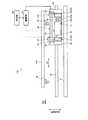
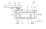
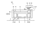
図1及び図2は、第1実施形態に係る三次元造形装置100の一例を示す図である。図1及び図2に示す三次元造形装置100は、作業面Fに造形材を積層することにより3次元の造形物を形成する。本実施形態では、三次元造形装置100は、いわゆるインクジェット法により、造形材としてインクを作業面Fに積層することで立体構造物を形成可能である。なお、図1は作業面Fに平行な一方向から三次元造形装置100を見た状態を示しており、図2は三次元造形装置100の作業面Fの法線方向から三次元造形装置100を見た状態を示している。本実施形態では、作業面Fが水平面に平行に配置される場合を例に挙げて説明するが、これに限定するものではない。また、以下の説明において、後述のキャリッジ40の移動方向を主走査方向D1とし、作業面F(水平面)に平行であって主走査方向D1に直交する方向を副走査方向D2とする。図1及び図2に示すように、三次元造形装置100は、ヘッド10と、光源部20と、光射出部30と、キャリッジ40と、相対移動部(光供給部)50と、制御部60とを備えている。
[First Embodiment]
FIG.1 and FIG.2 is a figure which shows an example of the three-dimensional modeling apparatus 100 which concerns on 1st Embodiment. The three-dimensional modeling apparatus 100 illustrated in FIGS. 1 and 2 forms a three-dimensional modeled object by stacking modeling materials on the work surface F. In the present embodiment, the three-dimensional modeling apparatus 100 can form a three-dimensional structure by laminating ink as a modeling material on the work surface F by a so-called inkjet method. 1 shows a state in which the 3D modeling apparatus 100 is viewed from one direction parallel to the work surface F, and FIG. 2 shows the 3D modeling apparatus 100 from the normal direction of the work surface F of the 3D modeling apparatus 100. Shows the state of seeing. In the present embodiment, the case where the work surface F is arranged in parallel to the horizontal plane will be described as an example, but the present invention is not limited to this. In the following description, a moving direction of a carriage 40 described later is a main scanning direction D1, and a direction parallel to the work surface F (horizontal plane) and orthogonal to the main scanning direction D1 is a sub-scanning direction D2. As shown in FIGS. 1 and 2, the three-dimensional modeling apparatus 100 includes a head 10, a light source unit 20, a light emitting unit 30, a carriage 40, a relative movement unit (light supply unit) 50, and a control unit 60. And.

ヘッド10は、造形材であるインクとして、所定波長の光、例えば紫外線を照射することで硬化する光硬化型のインクを作業面Fに吐出する。インクは、例えばキャリッジ40に搭載される不図示のインクタンクに貯留されている。ヘッド10は、インクを吐出する吐出面10aが作業面Fに平行に配置される。吐出面10aには、ノズル11が形成される。ノズル11は、水平面に平行であり主走査方向D1に直交する副走査方向D2に並んで配置され、ノズル列を構成している。各ノズル11は、各種インク流路、レギュレータ、ポンプ等を介してインクタンクと接続されている。ノズル列は、インクタンクの数、言い換えれば、同時に印刷可能なインクの種類の数等に応じて単数、あるいは複数が設けられる。インクの種類としては、例えば、製造する造形物Wの色彩に応じて、白色インク、着色インク、透明インク等を適宜用いることができる。   The head 10 ejects, on the work surface F, photocurable ink that is cured by irradiating light of a predetermined wavelength, for example, ultraviolet rays, as ink that is a modeling material. For example, the ink is stored in an ink tank (not shown) mounted on the carriage 40. In the head 10, an ejection surface 10 a that ejects ink is arranged in parallel to the work surface F. A nozzle 11 is formed on the discharge surface 10a. The nozzles 11 are arranged side by side in the sub-scanning direction D2 that is parallel to the horizontal plane and orthogonal to the main scanning direction D1, and constitute a nozzle row. Each nozzle 11 is connected to an ink tank through various ink flow paths, a regulator, a pump, and the like. One or a plurality of nozzle rows are provided according to the number of ink tanks, in other words, the number of types of ink that can be printed simultaneously. As the type of ink, for example, white ink, colored ink, transparent ink, and the like can be appropriately used according to the color of the modeled object W to be manufactured.

光源部20は、ヘッド10に対して鉛直方向の上方に配置される。光源部20は、1つ設けられている。光源部20は、筐体内に、例えば紫外線を射出可能な一又は複数の発光素子を有している。このような発光素子としては、例えばLED素子、ハロゲンランプ等を用いることができる。なお、本実施形態において、光源部20が1つであるとは、発光素子が1つだけ設けられる場合に限定されず、1つのユニットにおいて1箇所から射出される場合を含むものとする。したがって、例えば、光源部がアレイ状に配置された複数の発光素子を有する場合であっても、これら複数の発光素子からの光が1箇所から射出されるものであれば、1つの光源部に含まれる。光源部20は、後述のガイドレール51に沿って、主走査方向D1に移動可能である。光源部20は、突出部21を有している。突出部21は、筐体に固定され、当該筐体の鉛直方向上部に突出して設けられる。   The light source unit 20 is disposed above the head 10 in the vertical direction. One light source unit 20 is provided. The light source unit 20 has one or a plurality of light emitting elements capable of emitting ultraviolet light, for example, in the housing. As such a light emitting element, for example, an LED element, a halogen lamp, or the like can be used. In the present embodiment, the single light source unit 20 is not limited to the case where only one light emitting element is provided, but includes the case where light is emitted from one place in one unit. Therefore, for example, even when the light source unit has a plurality of light emitting elements arranged in an array, if the light from the plurality of light emitting elements is emitted from one place, one light source unit included. The light source unit 20 is movable in the main scanning direction D1 along a guide rail 51 described later. The light source unit 20 has a protruding portion 21. The protruding portion 21 is fixed to the housing and is provided to protrude in the upper part in the vertical direction of the housing.

光射出部30は、複数設けられ、光源部20からの光を作業面Fに照射する。複数の光射出部30は、2つの導光部材(第1光射出部)31及び32を有する。導光部材31及び32は、ヘッド10に対して主走査方向D1の両側に配置されている。   A plurality of light emitting units 30 are provided to irradiate the work surface F with light from the light source unit 20. The plurality of light emitting units 30 include two light guide members (first light emitting units) 31 and 32. The light guide members 31 and 32 are disposed on both sides of the head 10 in the main scanning direction D1.

キャリッジ40は、ヘッド10と、光源部20と、光射出部30(2つの導光部材31及び32)とを保持する。キャリッジ40は、キャリッジ駆動部41の駆動力により、ガイドレール42に沿って移動可能である。キャリッジ駆動部41は、例えばモータと、当該モータの回転力をキャリッジ40に伝達する回転ベルト機構とを有する構成とすることができるが、これに限定するものではなく、他の駆動機構であってもよい。ガイドレール42は、作業面Fに平行な一方向に直線状に形成される。上記のように、ガイドレール42が延びる方向が、キャリッジ40の移動方向であり、主走査方向D1である。キャリッジ40が主走査方向D1に移動することにより、ヘッド10及び光射出部30は、一体で主走査方向D1に移動する。   The carriage 40 holds the head 10, the light source unit 20, and the light emitting unit 30 (the two light guide members 31 and 32). The carriage 40 is movable along the guide rail 42 by the driving force of the carriage driving unit 41. The carriage drive unit 41 may be configured to include, for example, a motor and a rotating belt mechanism that transmits the rotational force of the motor to the carriage 40, but is not limited thereto, and may be another drive mechanism. Also good. The guide rail 42 is formed linearly in one direction parallel to the work surface F. As described above, the direction in which the guide rail 42 extends is the moving direction of the carriage 40 and is the main scanning direction D1. As the carriage 40 moves in the main scanning direction D1, the head 10 and the light emitting unit 30 move together in the main scanning direction D1.

また、キャリッジ40には、平坦化ローラユニット43が設けられている。平坦化ローラユニット43は、主走査方向D1について、ヘッド10と導光部材32との間に配置される。平坦化ローラユニット43は、作業面Fに吐出されたインクの層を平坦化するための構成である。平坦化ローラユニット43は、ヘッド10に対して上下方向に移動可能に設けられている。平坦化ローラユニット43は、平坦化ローラ43aを有している。平坦化ローラ43aは、キャリッジ40と一体で主走査方向D1へ移動し、流動可能な状態のインクの余剰造形材を掻き取る。平坦化ローラユニット43は、平坦化ローラ43aにより掻き取られた余剰インクを回収する不図示の回収機構を有している。本実施形態では、平坦化ローラユニット43がヘッド10に対して主走査方向D1の一方の側に配置された構成を例に挙げて説明するが、これに限定するものではなく、平坦化ローラユニット43がヘッド10に対して主走査方向D1の両側に配置された構成であってもよい。この場合、平坦化ローラユニット43は、主走査方向10について、例えばヘッド10と導光部材31との間の位置と、ヘッド10と導光部材32との間の位置と、にそれぞれ配置することができる。   The carriage 40 is provided with a flattening roller unit 43. The flattening roller unit 43 is disposed between the head 10 and the light guide member 32 in the main scanning direction D1. The flattening roller unit 43 is configured to flatten the ink layer discharged onto the work surface F. The flattening roller unit 43 is provided so as to be movable in the vertical direction with respect to the head 10. The flattening roller unit 43 has a flattening roller 43a. The flattening roller 43a moves in the main scanning direction D1 integrally with the carriage 40, and scrapes off the excess modeling material in a flowable state. The flattening roller unit 43 has a collection mechanism (not shown) that collects excess ink scraped off by the flattening roller 43a. In the present embodiment, a configuration in which the flattening roller unit 43 is arranged on one side of the head 10 in the main scanning direction D1 will be described as an example. However, the present invention is not limited to this, and the flattening roller unit is not limited thereto. 43 may be arranged on both sides of the head 10 in the main scanning direction D1. In this case, the flattening roller unit 43 is disposed in the main scanning direction 10 at, for example, a position between the head 10 and the light guide member 31 and a position between the head 10 and the light guide member 32. Can do.

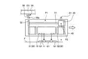
相対移動部50は、ガイドレール51と、ストッパ52、53と、規制部54、55とを有している。ガイドレール51は、キャリッジ40に固定され、主走査方向D1に平行に設けられている。ストッパ52、53は、ガイドレール51のうち主走査方向D1の両端に設けられている。ストッパ52、53は、光源部20の主走査方向D1への移動を停止させる。ストッパ52は、光源部20を第1位置P1で停止させる。第1位置P1は、光源部20から射出される光が導光部材31に供給される位置である。また、ストッパ53は、光源部20を第2位置P2で停止させる。第2位置P2は、光源部20から射出される光が導光部材32に供給される位置である。したがって、相対移動部50により、光源部20は、第1位置P1と第2位置P2との間を、ヘッド10に対して主走査方向D1に移動可能である。   The relative movement unit 50 includes a guide rail 51, stoppers 52 and 53, and regulation units 54 and 55. The guide rail 51 is fixed to the carriage 40 and is provided in parallel with the main scanning direction D1. The stoppers 52 and 53 are provided at both ends of the guide rail 51 in the main scanning direction D1. The stoppers 52 and 53 stop the movement of the light source unit 20 in the main scanning direction D1. The stopper 52 stops the light source unit 20 at the first position P1. The first position P <b> 1 is a position at which light emitted from the light source unit 20 is supplied to the light guide member 31. The stopper 53 stops the light source unit 20 at the second position P2. The second position P <b> 2 is a position where the light emitted from the light source unit 20 is supplied to the light guide member 32. Therefore, the light source unit 20 can move in the main scanning direction D1 with respect to the head 10 between the first position P1 and the second position P2 by the relative moving unit 50.

規制部54、55は、キャリッジ40が移動する場合に、光源部20の主走査方向D1への移動を規制する。図3は、規制部54の一例を示す図である。なお、規制部54及び55は、同一構成であるため、ここでは規制部54の構成を代表させて説明する。図3に示すように、規制部54は、取付部材56と、軸部材57と、当接部材58とを有している。   The restricting units 54 and 55 restrict the movement of the light source unit 20 in the main scanning direction D1 when the carriage 40 moves. FIG. 3 is a diagram illustrating an example of the restricting unit 54. In addition, since the control parts 54 and 55 are the same structures, the structure of the control part 54 is demonstrated here as a representative. As shown in FIG. 3, the restricting portion 54 includes an attachment member 56, a shaft member 57, and a contact member 58.

取付部材56は、例えば三次元造形装置100の筐体101の一部に固定されている。軸部材57は、円筒状又は円柱状に設けられており、作業面F(水平面)に平行であって主走査方向D1に直交する副走査方向D2に平行な中心軸AXを有している。当接部材58は、軸部材57から鉛直方向の下方に突出した状態となるように軸部材57に支持されている。当接部材58は、下側の端部58aが中心軸AXを中心とした円周方向に移動可能に設けられる。当接部材58は、下側の端部58aが下方に突出した状態で配置される場合に、光源部20の突出部21に当接可能となるように寸法が設定されている。   The attachment member 56 is fixed to a part of the housing 101 of the 3D modeling apparatus 100, for example. The shaft member 57 is provided in a cylindrical shape or a columnar shape, and has a central axis AX that is parallel to the work surface F (horizontal plane) and parallel to the sub-scanning direction D2 orthogonal to the main scanning direction D1. The contact member 58 is supported by the shaft member 57 so as to protrude downward from the shaft member 57 in the vertical direction. The contact member 58 is provided such that the lower end portion 58a is movable in the circumferential direction about the central axis AX. The size of the contact member 58 is set so that the contact member 58 can contact the protruding portion 21 of the light source unit 20 when the lower end portion 58a protrudes downward.

当接部材58と取付部材56との間には、不図示の弾性部材が設けられる。この弾性部材は、当接部材58の端部58aが中心軸AXを中心とした円周方向の両側に移動しようとする場合、それぞれの方向とは反対方向に弾性力を作用させる。したがって、当接部材58は、端部58aに対して当該弾性力よりも大きな力が作用する場合に、端部58aが中心軸AXを中心とした円周方向に移動可能となっている。なお、規制部54の構成としては、図3に示す構成に限定するものではなく、両開き型のバネ蝶番の構成が用いられてもよい。   An elastic member (not shown) is provided between the contact member 58 and the attachment member 56. When the end portion 58a of the contact member 58 tries to move on both sides in the circumferential direction around the central axis AX, the elastic member applies an elastic force in a direction opposite to each direction. Therefore, the contact member 58 is movable in the circumferential direction around the central axis AX when a force larger than the elastic force acts on the end 58a. In addition, as a structure of the control part 54, it is not limited to the structure shown in FIG. 3, The structure of a double-opening type spring hinge may be used.

また、図4は、規制部の他の例を示す図である。図4に示す規制部54Aは、球支持部66と、弾性部材67と、当接部材68とを有している。球支持部66は、例えば三次元造形装置100の筐体101の一部に固定されている。球支持部66は、鉛直方向の下端面から上方に向けた凹部66aを有している。弾性部材67は、凹部66aの上底部に固定されている。当接部材68は、弾性部材67の下端部に固定されている。当接部材68は、弾性部材67によって鉛直方向の下方に弾性力が加えられている。また、当接部材68は、球支持部66の鉛直方向の下端部に設けられるフランジ部66bに当接されている。当接部材68は、一部がフランジ部66bから鉛直方向の下方に突出した状態で保持されている。   FIG. 4 is a diagram illustrating another example of the restriction unit. The restriction portion 54 </ b> A illustrated in FIG. 4 includes a ball support portion 66, an elastic member 67, and a contact member 68. The sphere support 66 is fixed to a part of the housing 101 of the 3D modeling apparatus 100, for example. The sphere support 66 has a recess 66a directed upward from the lower end surface in the vertical direction. The elastic member 67 is fixed to the upper bottom portion of the recess 66a. The contact member 68 is fixed to the lower end portion of the elastic member 67. The abutting member 68 is applied with an elastic force downward in the vertical direction by the elastic member 67. Further, the contact member 68 is in contact with a flange portion 66 b provided at the lower end portion of the ball support portion 66 in the vertical direction. The contact member 68 is held in a state in which a part thereof protrudes downward in the vertical direction from the flange portion 66b.

したがって、当接部材68は、弾性部材67の弾性力よりも大きな力が鉛直方向の上方に作用する場合に、弾性部材67を押し上げて上方に移動し、全体が凹部66aに収容された状態となる。なお、当接部材68のうちフランジ部66bから下方に突出する部分の形状が球状であるため、例えば当接部材68の当該突出部分のうち主走査方向D1に面する部分に対して当該主走査方向D1から力を加えた場合、当接部材68に対して鉛直方向の上方に作用する力の成分が弾性部材67の弾性力よりも大きい場合、当接部材68が上方に移動して凹部66aに収容される。   Therefore, when a force larger than the elastic force of the elastic member 67 acts upward in the vertical direction, the abutting member 68 pushes up the elastic member 67 and moves upward, and the entire state is accommodated in the recess 66a. Become. In addition, since the shape of the portion of the contact member 68 that protrudes downward from the flange portion 66b is spherical, for example, the main scanning is performed on the portion of the protrusion of the contact member 68 that faces the main scanning direction D1. When a force is applied from the direction D1, if the component of the force acting on the contact member 68 in the vertical direction is larger than the elastic force of the elastic member 67, the contact member 68 moves upward to form the recess 66a. Is housed.

また、図1及び図2に示すように、制御部60は、ヘッド10、光源部20、キャリッジ駆動部41等を含む三次元造形装置100の各部を制御する。制御部60は、演算装置、メモリ等のハードウェア及びこれらの所定の機能を実現させるプログラムから構成される。制御部60は、ヘッド10を制御し、インクの吐出量、吐出のタイミング、吐出の期間等を制御する。制御部60は、光源部20を制御し、照射する紫外線の強度、照射タイミング、照射期間等を制御する。制御部60は、キャリッジ駆動部41を制御し、キャリッジ40の主走査方向D1への移動方向(往路、復路)、移動のタイミング、駆動力等を制御する。なお、例えば作業面Fが不図示の駆動部によって移動可能である場合、制御部60は、当該駆動部を制御し、作業面Fの移動方向、移動のタイミング等を制御してもよい。制御部60は、不図示の入力部に接続される。制御部60は、当該入力部により、造形対象物の形状に関する三次元データが入力される。なお、入力部としては、例えば、制御部60に有線又は無線で接続されるPC、種々の端末等によって構成される。   As shown in FIGS. 1 and 2, the control unit 60 controls each unit of the three-dimensional modeling apparatus 100 including the head 10, the light source unit 20, the carriage driving unit 41, and the like. The controller 60 includes hardware such as an arithmetic device and a memory, and a program that realizes these predetermined functions. The control unit 60 controls the head 10 to control the ink ejection amount, ejection timing, ejection period, and the like. The control unit 60 controls the light source unit 20 to control the intensity of ultraviolet rays to be irradiated, the irradiation timing, the irradiation period, and the like. The control unit 60 controls the carriage driving unit 41 to control the movement direction (forward path, backward path) of the carriage 40 in the main scanning direction D1, the timing of movement, the driving force, and the like. For example, when the work surface F can be moved by a drive unit (not shown), the control unit 60 may control the drive unit to control the moving direction of the work surface F, the timing of movement, and the like. The control unit 60 is connected to an input unit (not shown). The control unit 60 receives three-dimensional data related to the shape of the modeling target by the input unit. Note that the input unit includes, for example, a PC or various terminals connected to the control unit 60 by wire or wirelessly.

次に、上記のように構成された三次元造形装置100の動作を説明する。図5〜図14は、三次元造形装置100の動作の一例を示す図である。なお、図5〜図14では、平坦化ローラユニット43の図示を省略している。まず、制御部60に三次元データが入力された場合、制御部60は、キャリッジ駆動部41により、キャリッジ40を待機位置から主走査方向D1に移動させ、ヘッド10にインクの吐出を行わせる。以下、キャリッジ40の待機位置が主走査方向D1のうち図中の左側端部であり、キャリッジ40の往路移動方向が図中右方向、復路移動方向が図中左方向とする場合を例に挙げて説明するが、これに限定するものではない。   Next, the operation of the three-dimensional modeling apparatus 100 configured as described above will be described. 5-14 is a figure which shows an example of operation | movement of the three-dimensional modeling apparatus 100. FIG. 5 to 14, the flattening roller unit 43 is not shown. First, when three-dimensional data is input to the control unit 60, the control unit 60 causes the carriage driving unit 41 to move the carriage 40 from the standby position in the main scanning direction D1, and causes the head 10 to eject ink. Hereinafter, a case where the standby position of the carriage 40 is the left end portion in the figure in the main scanning direction D1, the forward movement direction of the carriage 40 is the right direction in the figure, and the return movement direction is the left direction in the figure is taken as an example. However, the present invention is not limited to this.

制御部60は、図5に示すように、待機位置に配置されるキャリッジ40を主走査方向D1のうち往路移動方向(図中右方向)に移動させる。この移動により、光源部20の筐体の上部に設けられた突出部21が当接部材58の下端部58a側に近づき、当該下端部58aに当接する。   As shown in FIG. 5, the control unit 60 moves the carriage 40 arranged at the standby position in the forward movement direction (right direction in the drawing) in the main scanning direction D1. By this movement, the protruding portion 21 provided on the upper portion of the casing of the light source unit 20 approaches the lower end 58a side of the contact member 58 and comes into contact with the lower end 58a.

突出部21が下端部58aに当接することにより、突出部21が下端部58aから図中右側に弾性力を受ける。この弾性力により、光源部20の図中右側への移動が規制される。このため、図6に示すように、キャリッジ40が図中右側に移動するのに伴い、見かけ上、キャリッジ40において光源部20が図中左側に押される状態となる。つまり、光源部20は、ヘッド10及び光射出部30に対して主走査方向D1(図中左方向)に相対的に移動する。   When the protruding portion 21 abuts on the lower end portion 58a, the protruding portion 21 receives an elastic force from the lower end portion 58a to the right side in the drawing. This elastic force restricts the movement of the light source unit 20 to the right side in the figure. For this reason, as shown in FIG. 6, as the carriage 40 moves to the right side in the figure, the light source unit 20 is apparently pushed to the left side in the figure in the carriage 40. That is, the light source unit 20 moves relative to the head 10 and the light emitting unit 30 in the main scanning direction D1 (left direction in the figure).

この相対移動を継続して行うことにより、図7に示すように、光源部20が第1位置P1でストッパ52に当接し、突出部21及び光源部20に対する図中左向きの力がストッパ52によって支持された状態となる。制御部60は、この状態から、キャリッジ駆動部41の駆動力を下端部58aからの弾性力よりも大きくなるように制御し、キャリッジ40を図中右側に移動させる。この制御により、図8に示すように、キャリッジ40の駆動力によって下端部58aが図中右側に押され、中心軸AXを中心として図中反時計回りに移動する。   By continuing this relative movement, as shown in FIG. 7, the light source unit 20 comes into contact with the stopper 52 at the first position P <b> 1, and the leftward force in the drawing with respect to the protrusion 21 and the light source unit 20 is exerted by the stopper 52. It becomes a supported state. From this state, the control unit 60 controls the driving force of the carriage driving unit 41 to be larger than the elastic force from the lower end 58a, and moves the carriage 40 to the right side in the drawing. By this control, as shown in FIG. 8, the lower end 58a is pushed to the right side in the figure by the driving force of the carriage 40, and moves counterclockwise around the central axis AX.

その後、突出部21が下端部58aを図中右側に通過した場合、突出部21に対して下端部58aから受けていた弾性力が解除される。このため、制御部60は、キャリッジ40の駆動力を戻してキャリッジ40を図中右側に移動させる。なお、当接部材58の下端部58aは、突出部21が通過した後、弾性力によって再び下方に突出した状態に戻される。   Thereafter, when the protruding portion 21 passes the lower end portion 58a to the right side in the drawing, the elastic force received from the lower end portion 58a with respect to the protruding portion 21 is released. Therefore, the control unit 60 returns the driving force of the carriage 40 and moves the carriage 40 to the right side in the drawing. Note that the lower end portion 58a of the contact member 58 is returned to a state in which the lower end portion 58a protrudes downward again by the elastic force after the protruding portion 21 has passed.

このとき、図9に示すように、光源部20がヘッド10に対してキャリッジ40の移動方向の後方である第1位置P1に配置された状態となる。この状態で、制御部60は、キャリッジ40を往路移動方向(図中右方向)に移動させ、所定のタイミングでノズル11からインクを吐出する。吐出されたインクQは、作業面Fに着弾し、所定の形状で配置される。また、制御部60は、光源部20から光Lを射出させる。光源部20が第1位置P1に配置されているため、この光Lは、導光部材31に供給され、当該導光部材31から作業面Fに射出される。導光部材31から射出された光Lは、作業面FにおいてインクQに照射される。これにより、インクQが硬化し、所定の形状を保持する。なお、ヘッド10と導光部材31との間に平坦化ローラユニット43が配置される場合、インクQが作業面Fに着弾した後、平坦化ローラユニット43の平坦化ローラ43aによってインクQの層を平坦化してもよい。この場合、導光部材31から射出された光Lは、平坦化された状態のインクQに照射される。このため、インクQは、平坦化された状態で硬化する。   At this time, as shown in FIG. 9, the light source unit 20 is disposed at the first position P <b> 1 that is behind the head 10 in the movement direction of the carriage 40. In this state, the control unit 60 moves the carriage 40 in the forward movement direction (right direction in the figure) and ejects ink from the nozzles 11 at a predetermined timing. The discharged ink Q lands on the work surface F and is arranged in a predetermined shape. In addition, the control unit 60 causes the light L to be emitted from the light source unit 20. Since the light source unit 20 is disposed at the first position P <b> 1, the light L is supplied to the light guide member 31 and is emitted from the light guide member 31 to the work surface F. The light L emitted from the light guide member 31 is applied to the ink Q on the work surface F. As a result, the ink Q is cured and maintains a predetermined shape. When the flattening roller unit 43 is disposed between the head 10 and the light guide member 31, the ink Q layer is formed by the flattening roller 43 a of the flattening roller unit 43 after the ink Q has landed on the work surface F. May be flattened. In this case, the light L emitted from the light guide member 31 is applied to the flattened ink Q. For this reason, the ink Q is cured in a flattened state.

往路の走査を終了した後、制御部60は、キャリッジ40を図中右側の中継位置に移動させる。このとき、光源部20が第1位置P1に配置された状態であるため、突出部21及び光源部20に対する図中左向きの力がストッパ52によって支持された状態となる。したがって、規制部55を右側に通過する場合、上記の規制部54を右側に通過する場合と同様に、制御部60は、キャリッジ駆動部41の駆動力を下端部58aからの弾性力よりも大きくなるように制御し、キャリッジ40を図中右側に移動させる。この制御により、図10に示すように、キャリッジ40の駆動力によって規制部55において下端部58aが図中右側に押され、中心軸AXを中心として図中反時計回りに移動する。そして、突出部21が下端部58aを図中右側に通過することにより、突出部21に対して下端部58aから受けていた弾性力が解除される。また、当接部材58の下端部58aは、突出部21が通過した後、弾性力によって再び下方に突出した状態に戻される。   After completing the forward scanning, the control unit 60 moves the carriage 40 to the relay position on the right side in the drawing. At this time, since the light source unit 20 is disposed at the first position P1, the leftward force in the drawing with respect to the protruding portion 21 and the light source unit 20 is supported by the stopper 52. Therefore, when passing through the restricting portion 55 on the right side, as in the case of passing through the restricting portion 54 on the right side, the control portion 60 makes the driving force of the carriage driving portion 41 larger than the elastic force from the lower end portion 58a. The carriage 40 is moved to the right side in the figure. By this control, as shown in FIG. 10, the lower end portion 58a of the restricting portion 55 is pushed to the right side in the drawing by the driving force of the carriage 40, and moves counterclockwise in the drawing about the central axis AX. And when the protrusion part 21 passes the lower end part 58a to the right side in a figure, the elastic force received from the lower end part 58a with respect to the protrusion part 21 is cancelled | released. Further, the lower end portion 58a of the abutting member 58 is returned to a state where it protrudes downward again by the elastic force after the protruding portion 21 has passed.

次に、制御部60は、復路の走査を行う。この場合、往路の走査時における動作に対して左右対称となる同様の動作が行われる。つまり、制御部60は、まず中継位置に配置されるキャリッジ40を復路移動方向(図中左方向)に移動させる。この移動により、突出部21が当接部材58の下端部58a側に近づき、当該下端部58aに当接する。突出部21が下端部58aに当接することにより、突出部21が下端部58aから図中右側に弾性力を受けるため、光源部20の図中左側への移動が規制される。このため、図11に示すように、キャリッジ40が図中左側に移動するのに伴い、見かけ上、キャリッジ40において光源部20が図中右側に押される状態となる。つまり、光源部20は、ヘッド10及び光射出部30に対して主走査方向D1(図中右方向)に相対的に移動する。   Next, the control unit 60 performs a backward scan. In this case, a similar operation is performed that is symmetrical with respect to the operation during forward scanning. That is, the control unit 60 first moves the carriage 40 arranged at the relay position in the backward movement direction (left direction in the figure). By this movement, the protruding portion 21 approaches the lower end portion 58a side of the contact member 58 and comes into contact with the lower end portion 58a. Since the protruding portion 21 abuts on the lower end portion 58a, the protruding portion 21 receives an elastic force from the lower end portion 58a to the right side in the figure, so that the movement of the light source part 20 to the left side in the figure is restricted. For this reason, as shown in FIG. 11, as the carriage 40 moves to the left side in the figure, the light source unit 20 is apparently pushed to the right side in the figure in the carriage 40. That is, the light source unit 20 moves relative to the head 10 and the light emitting unit 30 in the main scanning direction D1 (right direction in the drawing).

この相対移動により、光源部20が第2位置P2でストッパ53に当接され、突出部21及び光源部20に対する図中右向きの力がストッパ52によって支持された状態となる。制御部60は、キャリッジ駆動部41の駆動力を下端部58aからの弾性力よりも大きくなるように制御し、キャリッジ40を図中左側に移動させる。この制御により、図12に示すように、キャリッジ40の駆動力によって下端部58aが図中左側に押され、中心軸AXを中心として図中時計回りに移動する。   By this relative movement, the light source unit 20 is brought into contact with the stopper 53 at the second position P2, and the rightward force in the drawing with respect to the protruding portion 21 and the light source unit 20 is supported by the stopper 52. The control unit 60 controls the driving force of the carriage driving unit 41 so as to be larger than the elastic force from the lower end 58a, and moves the carriage 40 to the left side in the drawing. With this control, as shown in FIG. 12, the lower end 58a is pushed to the left in the figure by the driving force of the carriage 40, and moves clockwise around the central axis AX.

その後、突出部21が下端部58aを図中左側に通過した場合、突出部21に対して下端部58aから受けていた弾性力が解除される。このため、制御部60は、キャリッジ40の駆動力を戻してキャリッジ40を図中左側に移動させる。なお、当接部材58の下端部58aは、突出部21が通過した後、弾性力によって再び下方に突出した状態に戻される。これにより、光源部20がヘッド10に対してキャリッジ40の移動方向の後方である第2位置P2に配置された状態となる。この状態で、制御部60は、キャリッジ40を復路移動方向(図中左方向)に移動させ、所定のタイミングでノズル11からインクを吐出する。また、制御部60は、光源部20から光Lを射出させる。光源部20が第2位置P2に配置されているため、この光Lは、導光部材32に供給され、当該導光部材32から作業面Fに射出される。導光部材32から射出された光Lは、作業面FにおいてインクQに照射される。これにより、インクQが硬化し、所定の形状を保持する。なお、この場合においても、インクQが作業面Fに着弾した後、平坦化ローラ43aによってインクQの層を平坦化してもよい。この場合、導光部材32から射出された光Lは、平坦化された状態のインクQに照射される。このため、インクQは、平坦化された状態で硬化する。   Thereafter, when the protruding portion 21 passes the lower end portion 58a to the left in the drawing, the elastic force received from the lower end portion 58a with respect to the protruding portion 21 is released. Therefore, the control unit 60 returns the driving force of the carriage 40 and moves the carriage 40 to the left side in the drawing. Note that the lower end portion 58a of the contact member 58 is returned to a state in which the lower end portion 58a protrudes downward again by the elastic force after the protruding portion 21 has passed. As a result, the light source unit 20 is disposed at the second position P <b> 2 behind the head 10 in the movement direction of the carriage 40. In this state, the control unit 60 moves the carriage 40 in the backward movement direction (left direction in the figure) and ejects ink from the nozzles 11 at a predetermined timing. In addition, the control unit 60 causes the light L to be emitted from the light source unit 20. Since the light source unit 20 is disposed at the second position P2, the light L is supplied to the light guide member 32 and emitted from the light guide member 32 onto the work surface F. The light L emitted from the light guide member 32 is applied to the ink Q on the work surface F. As a result, the ink Q is cured and maintains a predetermined shape. In this case as well, after the ink Q has landed on the work surface F, the layer of the ink Q may be flattened by the flattening roller 43a. In this case, the light L emitted from the light guide member 32 is applied to the flattened ink Q. For this reason, the ink Q is cured in a flattened state.

なお、上記説明では、光源部20がヘッド10に対してキャリッジ40の移動方向の後方に配置された状態で光照射が行われる場合を例に挙げたが、これに限定するものではない。図13及び図14は、三次元造形装置100の動作の他の例を示す図である。図13及び図14に示すように、光源部20がヘッド10に対してキャリッジ40の移動方向の前方に配置された状態で光照射が行われてもよい。なお、図13及び図14では、キャリッジ40の直近の復路移動によって作業面FにインクQが配置され、かつインクQが光照射を受けていない状態を示している。   In the above description, the case where light irradiation is performed in a state where the light source unit 20 is arranged behind the head 10 in the movement direction of the carriage 40 is described as an example, but the present invention is not limited to this. 13 and 14 are diagrams showing another example of the operation of the three-dimensional modeling apparatus 100. FIG. As illustrated in FIGS. 13 and 14, light irradiation may be performed in a state where the light source unit 20 is disposed in front of the head 10 in the moving direction of the carriage 40. 13 and 14 show a state where the ink Q is arranged on the work surface F by the most recent backward movement of the carriage 40 and the ink Q is not irradiated with light.

制御部60は、図13に示すように、直近の復路移動によってヘッド10からインクQが作業面Fに配置されている状態で、キャリッジ40を図中左側に移動させる。そして、図13に示すように、制御部60は、突出部21が規制部54における当接部材58の端部58aに当接し、かつ光源部20が第2位置P2でストッパ53に当接した状態とする。このとき、光源部20及び突出部21は、当接部材58aの端部58aとストッパ53との間で挟まれた状態となる。制御部60は、このような状態になった場合に、図中左側へのキャリッジ40の移動を停止させる。したがって、規制部54によって突出部21が図中左側への移動を規制された状態で、キャリッジ40の移動が停止される。   As shown in FIG. 13, the control unit 60 moves the carriage 40 to the left side in the drawing in a state where the ink Q is arranged on the work surface F from the head 10 by the latest backward movement. Then, as shown in FIG. 13, the control unit 60 is configured such that the protruding portion 21 contacts the end portion 58a of the contact member 58 in the restricting portion 54, and the light source unit 20 contacts the stopper 53 at the second position P2. State. At this time, the light source part 20 and the protrusion part 21 will be in the state pinched | interposed between the edge part 58a of the contact member 58a, and the stopper 53. FIG. In such a state, the control unit 60 stops the movement of the carriage 40 to the left side in the drawing. Accordingly, the movement of the carriage 40 is stopped in a state where the protrusion 21 is restricted from moving leftward in the drawing by the restricting portion 54.

次に、制御部60は、キャリッジ40を往路走査方向(図中右方向)に移動させ、光源部20から光Lを射出させる。この制御により、図14に示すように、光源部20からの光Lが導光部材32に供給され、当該導光部材32から作業面Fに射出される。導光部材32から射出された光Lは、作業面FにおいてインクQに照射される。これにより、インクQが硬化し、所定の形状を保持する。また、制御部60は、所定のタイミングでノズル11からインクを吐出する。これにより、新たに吐出されたインクQが硬化したインクQに積層されて配置される。   Next, the control unit 60 moves the carriage 40 in the forward scanning direction (right direction in the drawing), and emits the light L from the light source unit 20. With this control, as shown in FIG. 14, the light L from the light source unit 20 is supplied to the light guide member 32 and is emitted from the light guide member 32 onto the work surface F. The light L emitted from the light guide member 32 is applied to the ink Q on the work surface F. As a result, the ink Q is cured and maintains a predetermined shape. The control unit 60 ejects ink from the nozzles 11 at a predetermined timing. As a result, the newly ejected ink Q is stacked and disposed on the cured ink Q.

なお、図14に示すように、光源部20がヘッド10に対してキャリッジ40の移動方向の前方に配置された状態でインクQを滴下して光照射を行う場合、作業面Fに着弾したインクQに光Lが照射されるまで、ある程度の時間が経過する。つまり、キャリッジ40が当該移動方向への移動を終え、主走査方向D1の端部で移動方向が切り替わった後、反対方向に移動するときまで、インクQに光Lが照射されないことになる。この時間経過により、インクQは、着弾時に比べて作業面Fの面方向に広がった形状に変化し、この状態で光Lの照射を受けて硬化する。よって、光源部20がヘッド10に対してキャリッジ40の移動方向の後方に配置された状態で光照射が行われる場合に対して、インクQの形状が異なる状態で硬化することになる。   As shown in FIG. 14, when the ink Q is dropped and light irradiation is performed with the light source unit 20 disposed in front of the head 10 in the movement direction of the carriage 40, the ink that has landed on the work surface F A certain amount of time passes until Q is irradiated with light L. That is, the ink L is not irradiated with the light L until the carriage 40 finishes moving in the moving direction, switches from the moving direction at the end of the main scanning direction D1, and then moves in the opposite direction. With the passage of time, the ink Q changes to a shape that expands in the surface direction of the work surface F as compared with the time of landing, and in this state is irradiated with the light L and is cured. Therefore, the ink Q is cured in a state where the shape of the ink Q is different from the case where light irradiation is performed in a state where the light source unit 20 is arranged behind the head 10 in the moving direction of the carriage 40.

以上のように、本実施形態に係る三次元造形装置100は、相対移動部50によって光源部20と2つの導光部材31、32とを相対的に移動させることにより、1つ設けられる光源部20から2つの導光部材31、32に光を供給可能である。このため、導光部材31、32毎に光源部20を設けなくても済む。これにより、装置全体の重量化を抑制することが可能となる。   As described above, in the three-dimensional modeling apparatus 100 according to the present embodiment, one light source unit is provided by relatively moving the light source unit 20 and the two light guide members 31 and 32 by the relative movement unit 50. Light can be supplied from 20 to the two light guide members 31 and 32. For this reason, it is not necessary to provide the light source unit 20 for each of the light guide members 31 and 32. Thereby, it becomes possible to suppress the weight of the whole apparatus.

また、本実施形態に係る三次元造形装置100は、規制部54、55がキャリッジ40の移動に対して光源部20の主走査方向D1への移動を規制することにより、キャリッジ40の移動を利用して光源部20と2つの導光部材31、32とを相対的に主走査方向D1へと相対的に移動させることができる。よって、光源部20を移動させる駆動源を設ける必要が無いため、装置全体の重量化の抑制に寄与することができる。なお、三次元造形装置100は、光源部20を移動させる駆動源が別途設けられる構成であってもよい。   Further, the three-dimensional modeling apparatus 100 according to the present embodiment uses the movement of the carriage 40 by the restriction units 54 and 55 restricting the movement of the light source unit 20 in the main scanning direction D1 with respect to the movement of the carriage 40. Thus, the light source unit 20 and the two light guide members 31 and 32 can be relatively moved in the main scanning direction D1. Therefore, there is no need to provide a drive source for moving the light source unit 20, which can contribute to suppressing the weight of the entire apparatus. Note that the three-dimensional modeling apparatus 100 may have a configuration in which a drive source for moving the light source unit 20 is separately provided.

[第2実施形態]
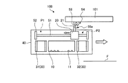
次に、第2実施形態を説明する。図15は、第2実施形態に係る三次元造形装置200の一例を示す図である。以下、第2実施形態では、第1実施形態に係る三次元造形装置100と同一の構成要素には同一の符号を付し、説明を省略又は簡略化する。図15に示す三次元造形装置200は、ヘッド10と、光源部120と、光射出部130と、キャリッジ40と、導光部(光供給部)150と、制御部160とを備えている。ヘッド部10及びキャリッジ40の構成については、第1実施形態と同一とすることができる。
[Second Embodiment]
Next, a second embodiment will be described. FIG. 15 is a diagram illustrating an example of the three-dimensional modeling apparatus 200 according to the second embodiment. Hereinafter, in 2nd Embodiment, the same code | symbol is attached | subjected to the same component as the three-dimensional modeling apparatus 100 which concerns on 1st Embodiment, and description is abbreviate | omitted or simplified. A three-dimensional modeling apparatus 200 illustrated in FIG. 15 includes a head 10, a light source unit 120, a light emitting unit 130, a carriage 40, a light guide unit (light supply unit) 150, and a control unit 160. About the structure of the head part 10 and the carriage 40, it can be made the same as 1st Embodiment.

光源部120は、キャリッジ40に固定されている。なお、光源部120自体の構造は、第1実施形態における光源部20と同一構造とすることができる。光射出部130は、光源部120からの光を作業面Fに照射する。光射出部130は、2つの光反射部材(第2光射出部)131及び132を有する。光反射部材131及び132は、ヘッド10に対して主走査方向D1の両側に配置されている。   The light source unit 120 is fixed to the carriage 40. In addition, the structure of light source part 120 itself can be made into the same structure as the light source part 20 in 1st Embodiment. The light emitting unit 130 irradiates the work surface F with light from the light source unit 120. The light emitting unit 130 includes two light reflecting members (second light emitting units) 131 and 132. The light reflecting members 131 and 132 are disposed on both sides of the head 10 in the main scanning direction D1.

導光部150は、光源部120からの光を光反射部材131及び132に対して切り替えて供給する。導光部150は、回転ミラー151と、ミラー駆動部152とを有している。回転ミラー151は、光源部120からの光を反射する。回転ミラー151は、例えば副走査方向D2に平行な回転軸を中心として回転可能に設けられる。なお、回転ミラー151は、鉛直方向に平行な回転軸を中心として回転可能であってもよい。ミラー駆動部152は、回転ミラー151による光の反射方向が光反射部材131に向けた方向と光反射部材132に向けた方向との間で切り替わるように、回転ミラー151を回転させる。   The light guide unit 150 switches and supplies the light from the light source unit 120 to the light reflecting members 131 and 132. The light guide unit 150 includes a rotating mirror 151 and a mirror driving unit 152. The rotating mirror 151 reflects light from the light source unit 120. The rotating mirror 151 is provided to be rotatable about a rotation axis parallel to the sub-scanning direction D2, for example. The rotating mirror 151 may be rotatable around a rotation axis parallel to the vertical direction. The mirror driving unit 152 rotates the rotating mirror 151 so that the direction of light reflection by the rotating mirror 151 is switched between the direction toward the light reflecting member 131 and the direction toward the light reflecting member 132.

制御部160は、ヘッド10、光源部120、キャリッジ駆動部41、ミラー駆動部152等を含む三次元造形装置100の各部を制御する。制御部160は、第1実施形態と同様に、ヘッド10、光源部120、キャリッジ駆動部41を制御する。また、制御部160は、ミラー駆動部152を制御し、回転ミラー151の位置及び姿勢、回転のタイミング等を制御する。   The control unit 160 controls each unit of the three-dimensional modeling apparatus 100 including the head 10, the light source unit 120, the carriage driving unit 41, the mirror driving unit 152, and the like. The control unit 160 controls the head 10, the light source unit 120, and the carriage drive unit 41 as in the first embodiment. The control unit 160 also controls the mirror driving unit 152 to control the position and posture of the rotating mirror 151, the timing of rotation, and the like.

次に、上記のように構成された三次元造形装置200の動作を説明する。制御部160に三次元データが入力された場合、制御部160は、キャリッジ駆動部41により、キャリッジ40を待機位置から往路走査方向に移動させ、ヘッド10にインクの吐出を行わせる。以下、例えば、キャリッジ40を主走査方向D1の図中右方向に移動させる場合について説明する。なお、キャリッジ40を主走査方向D1の図中左方向に移動させる場合については、左右を対称として同様の説明が可能である。   Next, the operation of the three-dimensional modeling apparatus 200 configured as described above will be described. When the three-dimensional data is input to the control unit 160, the control unit 160 causes the carriage driving unit 41 to move the carriage 40 from the standby position in the forward scanning direction, and causes the head 10 to eject ink. Hereinafter, for example, a case where the carriage 40 is moved to the right in the drawing in the main scanning direction D1 will be described. It should be noted that when the carriage 40 is moved to the left in the drawing in the main scanning direction D1, the same explanation can be made assuming that the left and right are symmetrical.

光源部120からの光Lをヘッド10に対してキャリッジ40の移動方向の後方に照射する場合、制御部160は、ミラー駆動部152を制御し、回転ミラー151による光の反射方向が光反射部材131に向けた方向とする。その後、制御部160は、キャリッジ40を主走査方向D1の図中右方向に移動させ、所定のタイミングでノズル11からインクを吐出する。吐出されたインクは、作業面Fに着弾し、所定の形状で配置される。また、制御部160は、光源部120から光Lを射出させる。光源部120からの光Lは、光反射部材131に向けて反射され、光反射部材131によって反射されて作業面Fに射出される。光反射部材131で反射されて射出された光Lは、作業面Fにおいてインクに照射される。これにより、インクQが硬化し、所定の形状を保持する。   When the light L from the light source unit 120 is irradiated to the head 10 backward in the moving direction of the carriage 40, the control unit 160 controls the mirror driving unit 152, and the light reflection direction by the rotating mirror 151 is a light reflecting member. The direction toward 131. Thereafter, the control unit 160 moves the carriage 40 to the right in the drawing in the main scanning direction D1, and discharges ink from the nozzles 11 at a predetermined timing. The ejected ink lands on the work surface F and is arranged in a predetermined shape. In addition, the control unit 160 causes the light L to be emitted from the light source unit 120. The light L from the light source unit 120 is reflected toward the light reflecting member 131, is reflected by the light reflecting member 131, and is emitted to the work surface F. The light L reflected and emitted from the light reflecting member 131 is applied to the ink on the work surface F. As a result, the ink Q is cured and maintains a predetermined shape.

また、光源部120からの光Lをヘッド10に対してキャリッジ40の移動方向の前方に照射する場合、制御部160は、ミラー駆動部152を制御し、回転ミラー151による光の反射方向が光反射部材132に向けた方向とする。その後、制御部160は、キャリッジ40を主走査方向D1の図中右方向に移動させ、光源部120から光Lを射出させる。光源部120からの光Lは、光反射部材131に向けて反射され、光反射部材131によって反射されて作業面Fに射出される。この光Lは、作業面FにおいてインクQに照射される。これにより、作業面Fに未硬化のインクが配置されている場合には、当該インクが硬化し、所定の形状を保持する。また、制御部60は、所定のタイミングでノズル11からインクを吐出する。これにより、新たに吐出されるインクが、硬化したインクに積層されて配置される。   Further, when the light L from the light source unit 120 is irradiated forward in the moving direction of the carriage 40 with respect to the head 10, the control unit 160 controls the mirror driving unit 152, and the light reflection direction by the rotating mirror 151 is light. The direction is toward the reflecting member 132. Thereafter, the control unit 160 moves the carriage 40 to the right in the drawing in the main scanning direction D1, and causes the light source unit 120 to emit light L. The light L from the light source unit 120 is reflected toward the light reflecting member 131, is reflected by the light reflecting member 131, and is emitted to the work surface F. This light L is applied to the ink Q on the work surface F. As a result, when uncured ink is disposed on the work surface F, the ink is cured and maintains a predetermined shape. The control unit 60 ejects ink from the nozzles 11 at a predetermined timing. As a result, newly ejected ink is disposed in a stacked manner on the cured ink.

このように、本実施形態に係る三次元造形装置200は、光源部120を移動させることなく、導光部150によって2つの光反射部材131、132に対して光Lを切り替えて供給することができる。これにより、光射出部130毎に光源部120を設けなくても済む。これにより、装置全体の重量化を抑制することが可能となる。また、光源部120からの光Lを2つの光反射部材131、132から効率的に射出させることが可能となる。   As described above, the 3D modeling apparatus 200 according to the present embodiment can switch and supply the light L to the two light reflecting members 131 and 132 by the light guide unit 150 without moving the light source unit 120. it can. Thereby, it is not necessary to provide the light source unit 120 for each light emitting unit 130. Thereby, it becomes possible to suppress the weight of the whole apparatus. In addition, the light L from the light source unit 120 can be efficiently emitted from the two light reflecting members 131 and 132.

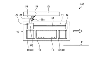
なお、上記第2実施形態では、光源部120からの光Lを導光部150によって2つの光反射部材131、132に対して光Lを切り替えて供給する場合を例に挙げて説明したが、これに限定するものではなく、例えば光Lを分岐して供給してもよい。図16は、他の例に係る三次元造形装置200Aの光源部120及び導光部150Aの構成を示す図である。図16に示す三次元造形装置200Aでは、導光部150Aは、光分岐部材151Aと、固定ミラー152Aとを有している。光分岐部材151Aは、半透過反射膜を有しており、光源部120からの光Lの一部である光L1を光反射部材131に反射すると共に、残りの光L2を固定ミラー152Aに向けて透過させる。固定ミラー152Aは、光L2を光反射部材132に向けて反射する。これにより、光源部120からの光Lを光反射部材131と光反射部材132とに同時に供給することができる。なお、光L1及び光L2の光路上にシャッタ等の遮光部材を設けることにより、光反射部材131、132への光の供給の有無を切り替えることが可能である。   In the second embodiment, the case where the light L from the light source unit 120 is switched and supplied to the two light reflecting members 131 and 132 by the light guide unit 150 is described as an example. For example, the light L may be branched and supplied. FIG. 16 is a diagram illustrating a configuration of the light source unit 120 and the light guide unit 150A of a three-dimensional modeling apparatus 200A according to another example. In the three-dimensional modeling apparatus 200A illustrated in FIG. 16, the light guide unit 150A includes a light branching member 151A and a fixed mirror 152A. The light branching member 151A has a transflective film, reflects the light L1 that is a part of the light L from the light source unit 120 to the light reflecting member 131, and directs the remaining light L2 to the fixed mirror 152A. Make it transparent. The fixed mirror 152A reflects the light L2 toward the light reflecting member 132. Thereby, the light L from the light source unit 120 can be simultaneously supplied to the light reflecting member 131 and the light reflecting member 132. In addition, by providing a light blocking member such as a shutter on the optical paths of the light L1 and the light L2, it is possible to switch whether light is supplied to the light reflecting members 131 and 132.

また、上記第2実施形態では、導光部150として、光反射部材131、132に代えて、例えば光ファイバが設けられた構成であってもよい。   Moreover, in the said 2nd Embodiment, it replaces with the light reflection members 131 and 132 as the light guide part 150, for example, the structure provided with the optical fiber may be sufficient.

[第3実施形態]
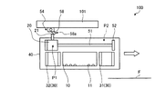
次に、第3実施形態を説明する。図17は、第3実施形態に係る三次元造形装置300の一例を示す図である。以下、第3実施形態では、第1実施形態に係る三次元造形装置100と同一の構成要素には同一の符号を付し、説明を省略又は簡略化する。図17に示す三次元造形装置200は、ヘッド310と、光源部320と、光射出部330と、キャリッジ40と、導光部(光供給部)350と、制御部360とを備えている。
[Third Embodiment]
Next, a third embodiment will be described. FIG. 17 is a diagram illustrating an example of the three-dimensional modeling apparatus 300 according to the third embodiment. Hereinafter, in 3rd Embodiment, the same code | symbol is attached | subjected to the same component as the three-dimensional modeling apparatus 100 which concerns on 1st Embodiment, and description is abbreviate | omitted or simplified. A three-dimensional modeling apparatus 200 shown in FIG. 17 includes a head 310, a light source unit 320, a light emitting unit 330, a carriage 40, a light guide unit (light supply unit) 350, and a control unit 360.

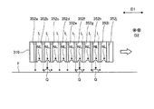
図18は、ヘッド部310を鉛直方向の下方から見た状態を示す図である。図18に示すように、ヘッド部310は、ノズル面310aに複数のノズル列NLを有している。ノズル列NLは、主走査方向D1に並んで配置される。各ノズル列NLには、副走査方向D2に複数のノズル311が並んで配置されている。   FIG. 18 is a diagram illustrating a state in which the head unit 310 is viewed from below in the vertical direction. As shown in FIG. 18, the head unit 310 has a plurality of nozzle rows NL on the nozzle surface 310a. The nozzle rows NL are arranged side by side in the main scanning direction D1. In each nozzle row NL, a plurality of nozzles 311 are arranged side by side in the sub-scanning direction D2.

また、図17に示すように、光源部320は、キャリッジ40に固定されている。光源部320自体の構造は、第1実施形態における光源部20と同一構造とすることができる。光射出部330は、光源320からの光を作業面Fに向けて射出する。光射出部330は、図18に示すように、ノズル面310aに複数設けられており、ノズル列NZに対して主走査方向D1の両側に配置されている。なお、光射出部330は、例えばノズル列NZに沿って副走査方向D2に延びた形状となっているが、これに限定するものではない。また、光射出部330は、例えば矩形の形状となっているが、これに限定するものではない。光射出部330には、例えば導光板が取り付けられており、光射出部330の全面から光が射出されるようになっている。   Further, as shown in FIG. 17, the light source unit 320 is fixed to the carriage 40. The structure of the light source unit 320 itself can be the same as that of the light source unit 20 in the first embodiment. The light emitting unit 330 emits light from the light source 320 toward the work surface F. As shown in FIG. 18, a plurality of light emitting portions 330 are provided on the nozzle surface 310a, and are arranged on both sides of the main scanning direction D1 with respect to the nozzle row NZ. In addition, although the light emission part 330 becomes the shape extended in the subscanning direction D2 along the nozzle row NZ, for example, it is not limited to this. Moreover, although the light emission part 330 becomes a rectangular shape, for example, it is not limited to this. For example, a light guide plate is attached to the light emitting unit 330, and light is emitted from the entire surface of the light emitting unit 330.

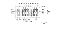
導光部350は、光源部320からの光が入射する光入射部351と、当該光入射部351に接続された複数の光ファイバ352(352a〜352j)とを有している。光入射部351としては、例えばMEMSスイッチ等の光スイッチが用いられる。光入射部351は、入射した光を複数の光ファイバ352の間で供給先を選択して供給する。複数の光ファイバ352は、ヘッド310の内部を通過して設けられ、光射出部330に取り回されている。したがって、光源部320からの光は、光入射部351に入射した後、光ファイバ352を通過して光射出部330に供給され、当該光射出部330から作業面Fに射出される。   The light guide unit 350 includes a light incident unit 351 into which light from the light source unit 320 is incident, and a plurality of optical fibers 352 (352a to 352j) connected to the light incident unit 351. As the light incident part 351, for example, an optical switch such as a MEMS switch is used. The light incident unit 351 supplies the incident light by selecting a supply destination among the plurality of optical fibers 352. The plurality of optical fibers 352 are provided so as to pass through the inside of the head 310, and are routed around the light emitting unit 330. Therefore, the light from the light source unit 320 enters the light incident unit 351, passes through the optical fiber 352, is supplied to the light emitting unit 330, and is emitted from the light emitting unit 330 to the work surface F.

次に、上記のように構成された三次元造形装置300の動作を説明する。制御部360に三次元データが入力された場合、制御部360は、キャリッジ駆動部41により、キャリッジ40を待機位置から主走査方向D1に移動させ、ヘッド310にインクの吐出を行わせる。以下、例えば、キャリッジ40を主走査方向D1の図中右方向に移動させる場合について説明する。なお、キャリッジ40を主走査方向D1の図中左方向に移動させる場合については、左右を対称として同様の説明が可能である。   Next, the operation of the three-dimensional modeling apparatus 300 configured as described above will be described. When the three-dimensional data is input to the control unit 360, the control unit 360 causes the carriage driving unit 41 to move the carriage 40 from the standby position in the main scanning direction D1, and causes the head 310 to eject ink. Hereinafter, for example, a case where the carriage 40 is moved to the right in the drawing in the main scanning direction D1 will be described. It should be noted that when the carriage 40 is moved to the left in the drawing in the main scanning direction D1, the same explanation can be made assuming that the left and right are symmetrical.

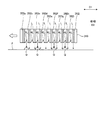
例えば、光源部320からの光Lをヘッド310に対してキャリッジ40の移動方向の後方に照射する場合、キャリッジ40を主走査方向D1の図中右方向に移動させ、所定のタイミングで所定のノズル列NZのノズル311からインクを吐出する。吐出されたインクQは、作業面Fに着弾し、所定の形状で配置される。また、制御部360は、光源部320から光Lを射出させる。光源320からの光は、光ファイバ352に導光される。このとき、制御部360は、図19に示すように、インクの吐出を行ったノズル列NZに対して主走査方向D1の左隣の光射出部330に接続される光ファイバ352を選択して光Lを供給する。この場合、複数の光ファイバ352のうち、例えば光ファイバ352b、352f、352hに対して光Lを供給する。これにより、作業面Fに吐出されたインクQに対して短時間で光Lが照射されることになる。光反射部材131で反射されて射出された光Lは、作業面Fにおいてインクに照射される。これにより、インクQが硬化し、所定の形状を保持する。   For example, when the light L from the light source unit 320 is irradiated to the head 310 backward in the movement direction of the carriage 40, the carriage 40 is moved to the right in the drawing in the main scanning direction D1, and a predetermined nozzle is formed at a predetermined timing. Ink is ejected from the nozzles 311 in the row NZ. The discharged ink Q lands on the work surface F and is arranged in a predetermined shape. In addition, the control unit 360 causes the light source unit 320 to emit light L. Light from the light source 320 is guided to the optical fiber 352. At this time, as shown in FIG. 19, the control unit 360 selects the optical fiber 352 connected to the light emitting unit 330 on the left side in the main scanning direction D1 with respect to the nozzle row NZ that has ejected ink. Supply light L. In this case, among the plurality of optical fibers 352, for example, the light L is supplied to the optical fibers 352b, 352f, and 352h. Thereby, the light L is irradiated to the ink Q discharged to the work surface F in a short time. The light L reflected and emitted from the light reflecting member 131 is applied to the ink on the work surface F. As a result, the ink Q is cured and maintains a predetermined shape.

また、作業面Fに光Lを照射する場合、制御部360は、図20に示すように、複数の光射出部330のうち、キャリッジ40の移動方向の先頭の光射出部330以外の光射出部330に接続された光ファイバ352(図20では、光ファイバ352a〜352i)を選択して光Lを供給してもよい。また、キャリッジ40の移動方向が切り替わった場合に、光Lの供給先の光ファイバ352を切り替えるようにする。例えば、図21に示すように、キャリッジ40の移動方向が図中左方向に切り替わった場合、移動方向の先頭の光射出部330以外の光射出部330に接続された光ファイバ352(図21では、光ファイバ352b〜352j)を選択して光Lを供給する。   Further, when the work surface F is irradiated with the light L, the control unit 360 emits light other than the head light emitting unit 330 in the moving direction of the carriage 40 among the plurality of light emitting units 330, as shown in FIG. The optical fiber 352 (in FIG. 20, optical fibers 352a to 352i) connected to the unit 330 may be selected to supply the light L. Further, when the moving direction of the carriage 40 is switched, the optical fiber 352 to which the light L is supplied is switched. For example, as shown in FIG. 21, when the moving direction of the carriage 40 is switched to the left in the figure, an optical fiber 352 connected to a light emitting unit 330 other than the leading light emitting unit 330 in the moving direction (in FIG. 21) , The optical fibers 352b to 352j) are selected to supply the light L.

したがって、この制御においては、いずれのノズル列NLからインクQが吐出される場合であっても、作業面Fに吐出されたインクQに対して短時間で光Lが照射されることになる。また、インクQを吐出するノズル列NLに応じて光Lの供給先を切り替える必要が無いため、制御を単純化することができる。   Therefore, in this control, even if the ink Q is ejected from any nozzle row NL, the light L is irradiated to the ink Q ejected on the work surface F in a short time. Further, since it is not necessary to switch the supply destination of the light L according to the nozzle row NL that ejects the ink Q, the control can be simplified.

以上のように、本実施形態に係る三次元造形装置300は、光源部320を移動させることなく、導光部350によって複数の光射出部330に対して光Lを切り替えて供給することができる。これにより、光射出部330毎に光源部320を設けなくても済む。これにより、装置全体の重量化を抑制することが可能となる。また、光ファイバ352を介して光射出部330に光Lを導光するため、ノズル列NLの間等、狭いスペースであっても光Lを供給する。   As described above, the three-dimensional modeling apparatus 300 according to this embodiment can switch and supply the light L to the plurality of light emitting units 330 by the light guide unit 350 without moving the light source unit 320. . Thereby, it is not necessary to provide the light source unit 320 for each light emitting unit 330. Thereby, it becomes possible to suppress the weight of the whole apparatus. Further, since the light L is guided to the light emitting unit 330 through the optical fiber 352, the light L is supplied even in a narrow space such as between the nozzle rows NL.

本発明の技術範囲は上記実施形態に限定されるものではなく、本発明の趣旨を逸脱しない範囲で適宜変更を加えることができる。本実施形態に係る三次元造形装置100、200、200A、300は、上記の各実施形態、変形例の構成要素を適宜組み合わせることで構成してもよい。   The technical scope of the present invention is not limited to the above-described embodiment, and appropriate modifications can be made without departing from the spirit of the present invention. The three-dimensional modeling apparatuses 100, 200, 200A, and 300 according to the present embodiment may be configured by appropriately combining the constituent elements of the above-described embodiments and modifications.

また、三次元造形装置100、200、200A、300において、白色インク、着色インク、透明インク等を複数種類用いて複数の色彩を有する造形対象物を製造することも可能である。この場合、三次元造形装置100、200、200A、300は、例えば、異なる色のインクや透明インクごとに各層を形成していくと共に、異なる色のインク間や各層における非着色部分に透明インクを介在させるなどして、造形対象物を形成していけばよい。また、上記の三次元造形装置100、200、200A、300は、作業面と造形インクとの間に離型剤を介在させてもよい。   In the three-dimensional modeling apparatuses 100, 200, 200A, and 300, it is also possible to manufacture a modeling object having a plurality of colors using a plurality of types of white ink, colored ink, transparent ink, and the like. In this case, for example, the 3D modeling apparatus 100, 200, 200A, 300 forms each layer for each different color ink or transparent ink, and applies the transparent ink between the different color inks or in the non-colored portion in each layer. What is necessary is just to form a modeling target object by interposing. Moreover, said 3D modeling apparatus 100,200,200A, 300 may interpose a mold release agent between a working surface and modeling ink.

10 ヘッド
11 ノズル
20,120 光源部
21 突出部
30,130、330 光射出部
31,32 導光部材
40 キャリッジ
41 キャリッジ駆動部
43 平坦化ローラユニット
50 相対移動部
52,53 ストッパ
54,54A,55 規制部
60,160 制御部
100,200,200A、300 三次元造形装置
131,132 光反射部材
150,150A、350 導光部
351 光入射部
352、352a〜352j 光ファイバ
D1 主走査方向
D2 副走査方向
F 作業面
L,L1,L2 光
P1 第1位置
P2 第2位置
Q インク
DESCRIPTION OF SYMBOLS 10 Head 11 Nozzle 20,120 Light source part 21 Protrusion part 30,130,330 Light emission part 31,32 Light guide member 40 Carriage 41 Carriage drive part 43 Flattening roller unit 50 Relative moving part 52,53 Stopper 54,54A, 55 Regulating unit 60, 160 Control unit 100, 200, 200A, 300 Three-dimensional modeling apparatus 131, 132 Light reflecting member 150, 150A, 350 Light guide unit 351 Light incident unit 352, 352a-352j Optical fiber D1 Main scanning direction D2 Sub scanning Direction F Work surface L, L1, L2 Light P1 First position P2 Second position Q Ink

Claims (7)

主走査方向に移動可能に設けられ、所定波長の光が照射されることで硬化度が変化するインクを作業面に吐出するヘッドと、
前記光を発光する1つの光源部と、
前記光を前記作業面に射出可能な複数の光射出部と、
1つの前記光源部からの前記光を前記複数の光射出部の少なくとも1つに供給可能であり、かつ、前記光の供給先を前記複数の光射出部の間で変更可能な光供給部と
を備える三次元造形装置。
A head that is movably provided in the main scanning direction, and that ejects ink whose degree of cure is changed by irradiation with light of a predetermined wavelength,
One light source that emits the light;
A plurality of light emitting portions capable of emitting the light to the work surface;
A light supply unit capable of supplying the light from one light source unit to at least one of the plurality of light emission units and capable of changing a supply destination of the light among the plurality of light emission units; 3D modeling device.
前記複数の光射出部は、前記ヘッドに対して前記主走査方向の両側に配置され、前記ヘッドと一体で前記主走査方向に移動可能であり、前記光を導光して前記作業面に向けて射出する2つの第1光射出部を有し、
前記光供給部は、前記光源部がそれぞれの前記第1光射出部に前記光を供給可能な位置に配置されるように前記光源部と2つの前記第1光射出部とを相対的に移動させる相対移動部を有する請求項1に記載の三次元造形装置。
The plurality of light emitting portions are disposed on both sides in the main scanning direction with respect to the head, are movable with the head in the main scanning direction, and guides the light toward the work surface. Two first light emitting portions that emit
The light supply unit relatively moves the light source unit and the two first light emission units such that the light source unit is disposed at a position where the light can be supplied to each first light emission unit. The three-dimensional modeling apparatus according to claim 1, further comprising a relative movement unit to be moved.
前記ヘッドと、前記光源部と、2つの前記第1光射出部とを保持して前記主走査方向に移動可能なキャリッジと、
前記キャリッジを前記主走査方向に移動させる駆動部と、をさらに備え、
前記相対移動部は、前記キャリッジの移動に対して前記光源部の前記主走査方向への移動を規制する規制部を有する請求項2に記載の三次元造形装置。
A carriage that holds the head, the light source unit, and the two first light emitting units and is movable in the main scanning direction;
A drive unit that moves the carriage in the main scanning direction;
The three-dimensional modeling apparatus according to claim 2, wherein the relative movement unit includes a regulation unit that regulates movement of the light source unit in the main scanning direction with respect to movement of the carriage.
前記複数の光射出部は、前記ヘッドと一体で前記主走査方向に移動可能であり、前記光を前記作業面に向けて射出する複数の第2光射出部を有し、
前記光供給部は、前記光源部からの前記光を複数の前記第2光射出部に対して切り替えて、又は分岐して供給する導光部を有する請求項1に記載の三次元造形装置。
The plurality of light emission units are movable in the main scanning direction integrally with the head, and have a plurality of second light emission units for emitting the light toward the work surface,
The three-dimensional modeling apparatus according to claim 1, wherein the light supply unit includes a light guide unit that switches or supplies the light from the light source unit to a plurality of the second light emission units.
前記導光部は、前記光源からの前記光が入射する光入射部と、前記光入射部と複数の前記第2光射出部とを接続する複数の光ファイバとを有し、
前記光供給部は、前記光入射部に入射した前記光の供給先を複数の前記光ファイバから選択して供給する制御部を有する請求項4に記載の三次元造形装置。
The light guide unit includes a light incident unit on which the light from the light source is incident, and a plurality of optical fibers that connect the light incident unit and the plurality of second light emitting units,
The three-dimensional modeling apparatus according to claim 4, wherein the light supply unit includes a control unit that selects and supplies a supply destination of the light incident on the light incident unit from a plurality of the optical fibers.
前記ヘッドは、前記主走査方向に並んで配置され互いに異なる種類の前記インクを吐出するノズル列を有し、
前記第2光射出部は、前記ノズル列に対して前記主走査方向の両側に配置される請求項5に記載の三次元造形装置。
The head includes nozzle rows that are arranged side by side in the main scanning direction and eject different types of ink.
The three-dimensional modeling apparatus according to claim 5, wherein the second light emitting units are arranged on both sides in the main scanning direction with respect to the nozzle row.
前記制御部は、前記ヘッドが前記主走査方向のうち所定方向に移動する間に前記インクを吐出する場合には、複数の前記光ファイバのうち前記ノズル列に対して前記所定方向の後方の前記第2光射出部に接続される前記光ファイバに対して前記光を供給させる請求項6に記載の三次元造形装置。   The controller, when ejecting the ink while the head moves in a predetermined direction in the main scanning direction, the rear of the nozzle array among the plurality of optical fibers in the predetermined direction. The three-dimensional modeling apparatus according to claim 6, wherein the light is supplied to the optical fiber connected to the second light emitting unit.
JP2016104486A 2016-05-25 2016-05-25 Three-dimensional molding apparatus Pending JP2017209871A (en)

Priority Applications (1)

Application Number Priority Date Filing Date Title
JP2016104486A JP2017209871A (en) 2016-05-25 2016-05-25 Three-dimensional molding apparatus

Applications Claiming Priority (1)

Application Number Priority Date Filing Date Title
JP2016104486A JP2017209871A (en) 2016-05-25 2016-05-25 Three-dimensional molding apparatus

Publications (1)

Publication Number Publication Date
JP2017209871A true JP2017209871A (en) 2017-11-30

Family

ID=60475837

Family Applications (1)

Application Number Title Priority Date Filing Date
JP2016104486A Pending JP2017209871A (en) 2016-05-25 2016-05-25 Three-dimensional molding apparatus

Country Status (1)

Country Link
JP (1) JP2017209871A (en)

Citations (6)

* Cited by examiner, † Cited by third party
Publication number Priority date Publication date Assignee Title
WO2000021735A1 (en) * 1998-10-12 2000-04-20 Dicon A/S Rapid prototyping apparatus and method of rapid prototyping
JP2004230692A (en) * 2003-01-30 2004-08-19 Dainippon Screen Mfg Co Ltd Shaping apparatus
JP2004330702A (en) * 2003-05-09 2004-11-25 Fuji Photo Film Co Ltd Method and apparatus for manufacturing three-dimensional shaped article
JP2012106437A (en) * 2010-11-18 2012-06-07 Sony Corp 3-dimensional modeling apparatus, 3-dimensional modeling method and modeled object
JP2015208904A (en) * 2014-04-25 2015-11-24 コニカミノルタ株式会社 Three-dimensional molding apparatus
JP2016047603A (en) * 2014-08-27 2016-04-07 株式会社ミマキエンジニアリング Three-dimensional article molding apparatus and method for manufacturing three-dimensional article

Patent Citations (6)

* Cited by examiner, † Cited by third party
Publication number Priority date Publication date Assignee Title
WO2000021735A1 (en) * 1998-10-12 2000-04-20 Dicon A/S Rapid prototyping apparatus and method of rapid prototyping
JP2004230692A (en) * 2003-01-30 2004-08-19 Dainippon Screen Mfg Co Ltd Shaping apparatus
JP2004330702A (en) * 2003-05-09 2004-11-25 Fuji Photo Film Co Ltd Method and apparatus for manufacturing three-dimensional shaped article
JP2012106437A (en) * 2010-11-18 2012-06-07 Sony Corp 3-dimensional modeling apparatus, 3-dimensional modeling method and modeled object
JP2015208904A (en) * 2014-04-25 2015-11-24 コニカミノルタ株式会社 Three-dimensional molding apparatus
JP2016047603A (en) * 2014-08-27 2016-04-07 株式会社ミマキエンジニアリング Three-dimensional article molding apparatus and method for manufacturing three-dimensional article

Similar Documents

Publication Publication Date Title
EP2455211B1 (en) 3D modeling apparatus for manufacturing of colored objects
KR102075856B1 (en) Apparatus and method for increasing adhesion of a component layer to a carrier object
US10625497B2 (en) Three-dimensional printing apparatus and three-dimensional printing method
EP3476575B1 (en) Photocuring 3d printer
US10994474B2 (en) Method for printing a three-dimensional light guiding structure by curing droplets of a printing material by light irradiation
WO2011099557A1 (en) Inkjet printer
JP2009202418A (en) Inkjet printer, printing unit, and its printing method
US8235520B2 (en) Droplet discharge device and droplet discharge method
JP2018065308A (en) Molding apparatus and molding method
JP7129822B2 (en) LIQUID EJECTING APPARATUS AND LIQUID EJECTING METHOD
JP2017209871A (en) Three-dimensional molding apparatus
US20190366624A1 (en) Stereolithography machine with improved optical group
US20180043720A1 (en) Printing device and printing method
US11926147B2 (en) Printing device including light radiation device with independently controlled radiation portions
JP5928631B2 (en) 3D modeling apparatus and 3D modeling method
CN207630510U (en) A kind of light-source system of visible-light curing 3D printing
JP2011083910A (en) Ultraviolet irradiation device and inkjet printer
JP2021109390A (en) Liquid discharge device and liquid discharge method
CN108215152A (en) A kind of light-source system of visible-light curing 3D printing
JP6310218B2 (en) Inkjet printer
JP2018065359A (en) Three-dimensional molding device
JP2012206449A (en) Recorder

Legal Events

Date Code Title Description
A621 Written request for application examination

Free format text: JAPANESE INTERMEDIATE CODE: A621

Effective date: 20180802

A977 Report on retrieval

Free format text: JAPANESE INTERMEDIATE CODE: A971007

Effective date: 20190523

A131 Notification of reasons for refusal

Free format text: JAPANESE INTERMEDIATE CODE: A131

Effective date: 20190528

A02 Decision of refusal

Free format text: JAPANESE INTERMEDIATE CODE: A02

Effective date: 20191203