JP2017209629A - Exhaust gas processing device and method for conducting maintenance of the same - Google Patents
Exhaust gas processing device and method for conducting maintenance of the same Download PDFInfo
- Publication number
- JP2017209629A JP2017209629A JP2016104641A JP2016104641A JP2017209629A JP 2017209629 A JP2017209629 A JP 2017209629A JP 2016104641 A JP2016104641 A JP 2016104641A JP 2016104641 A JP2016104641 A JP 2016104641A JP 2017209629 A JP2017209629 A JP 2017209629A
- Authority
- JP
- Japan
- Prior art keywords
- divided body
- exhaust gas
- flange portion
- height direction
- gas treatment
- Prior art date
- Legal status (The legal status is an assumption and is not a legal conclusion. Google has not performed a legal analysis and makes no representation as to the accuracy of the status listed.)
- Pending
Links
Images


Classifications
-
- B—PERFORMING OPERATIONS; TRANSPORTING
- B01—PHYSICAL OR CHEMICAL PROCESSES OR APPARATUS IN GENERAL
- B01D—SEPARATION
- B01D53/00—Separation of gases or vapours; Recovering vapours of volatile solvents from gases; Chemical or biological purification of waste gases, e.g. engine exhaust gases, smoke, fumes, flue gases, aerosols
- B01D53/34—Chemical or biological purification of waste gases
- B01D53/92—Chemical or biological purification of waste gases of engine exhaust gases
-
- F—MECHANICAL ENGINEERING; LIGHTING; HEATING; WEAPONS; BLASTING
- F01—MACHINES OR ENGINES IN GENERAL; ENGINE PLANTS IN GENERAL; STEAM ENGINES
- F01N—GAS-FLOW SILENCERS OR EXHAUST APPARATUS FOR MACHINES OR ENGINES IN GENERAL; GAS-FLOW SILENCERS OR EXHAUST APPARATUS FOR INTERNAL COMBUSTION ENGINES
- F01N13/00—Exhaust or silencing apparatus characterised by constructional features ; Exhaust or silencing apparatus, or parts thereof, having pertinent characteristics not provided for in, or of interest apart from, groups F01N1/00 - F01N5/00, F01N9/00, F01N11/00
-
- F—MECHANICAL ENGINEERING; LIGHTING; HEATING; WEAPONS; BLASTING
- F01—MACHINES OR ENGINES IN GENERAL; ENGINE PLANTS IN GENERAL; STEAM ENGINES
- F01N—GAS-FLOW SILENCERS OR EXHAUST APPARATUS FOR MACHINES OR ENGINES IN GENERAL; GAS-FLOW SILENCERS OR EXHAUST APPARATUS FOR INTERNAL COMBUSTION ENGINES
- F01N3/00—Exhaust or silencing apparatus having means for purifying, rendering innocuous, or otherwise treating exhaust
Abstract
Description
本発明は、排ガス処理装置および排ガス処理装置をメンテナンスする方法に関する。 The present invention relates to an exhaust gas treatment device and a method for maintaining an exhaust gas treatment device.
従来、反応塔内部に導入した排ガスと、反応塔内部に設けられたノズルから噴射される液体とを気液接触させることにより、排ガス中の硫黄酸化物(SOx)等を除去していた。
[先行技術文献]
[特許文献]
Conventionally, sulfur oxides (SOx) and the like in exhaust gas have been removed by gas-liquid contact between the exhaust gas introduced into the reaction tower and the liquid ejected from the nozzle provided in the reaction tower.
[Prior art documents]
[Patent Literature]
[特許文献1]特開平06−190240号公報
[特許文献2]特開平08−281055号公報
[Patent Document 1] Japanese Patent Application Laid-Open No. 06-190240 [Patent Document 2] Japanese Patent Application Laid-Open No. 08-281055
反応塔内部に設けられたノズルは、定期的にメンテナンスする必要がある。ノズルをメンテナンスすることを目的としてクレーン等を用いて反応塔を排ガス処理装置から取り外す場合には、クレーンを設置するスペースおよびクレーンを設けるコストが必要となる。 The nozzle provided in the reaction tower needs to be regularly maintained. When removing the reaction tower from the exhaust gas treatment apparatus using a crane or the like for the purpose of maintaining the nozzle, a space for installing the crane and a cost for installing the crane are required.
本発明の第1の態様においては、排ガスが導入される底部側から処理した排ガスが排出される上部側への高さ方向に延伸する内部空間を有する反応塔を備える排ガス処理装置を提供する。反応塔は外筒を有してよい。排ガスを処理する位置に反応塔を設置した状態において、外筒の少なくとも一部は高さ方向と平行な方向に移動可能であってよい。 According to a first aspect of the present invention, there is provided an exhaust gas treatment apparatus including a reaction tower having an internal space extending in a height direction from a bottom side where exhaust gas is introduced to an upper side where treated exhaust gas is discharged. The reaction tower may have an outer cylinder. In a state where the reaction tower is installed at a position where the exhaust gas is treated, at least a part of the outer cylinder may be movable in a direction parallel to the height direction.
外筒は、第1の分割体と、第2の分割体とを有してよい。第2の分割体は、第1の分割体の内径よりも小さな外径を有してよい。排ガス処理装置は、移動機構をさらに備えてよい。移動機構は、第1の分割体および第2の分割体のいずれかを高さ方向と平行な方向に移動してよい。 The outer cylinder may have a first divided body and a second divided body. The second divided body may have an outer diameter smaller than the inner diameter of the first divided body. The exhaust gas treatment device may further include a moving mechanism. The moving mechanism may move either the first divided body or the second divided body in a direction parallel to the height direction.
第2の分割体は第1の分割体よりも高さ方向に設けられてよい。 The second divided body may be provided in the height direction than the first divided body.
移動機構は、棒部材と、駆動部とを有してよい。棒部材は、第1のフランジ部と第2のフランジ部とを連結してよい。第1のフランジ部は、第1の分割体において高さ方向と平行な方向における端部領域に位置してよい。第2のフランジ部は、第2の分割体において高さ方向と平行な方向における端部領域に位置してよい。駆動部は、第1の分割体および第2の分割体のいずれかを高さ方向と平行な方向に移動させてよい。 The moving mechanism may include a bar member and a drive unit. The bar member may connect the first flange portion and the second flange portion. The first flange portion may be positioned in an end region in a direction parallel to the height direction in the first divided body. A 2nd flange part may be located in the edge part area | region in the direction parallel to a height direction in a 2nd division body. The drive unit may move either the first divided body or the second divided body in a direction parallel to the height direction.
棒部材は、ねじ切りされた表面を有してよい。駆動部は、ナット部を有してよい。ナット部は、棒部材において高さ方向と平行な方向に移動可能であってよい。ナット部は、第1のフランジ部および第2のフランジ部のいずれかに接触して、第1の分割体および第2の分割体のいずれかを支えることができてよい。 The bar member may have a threaded surface. The drive part may have a nut part. The nut portion may be movable in a direction parallel to the height direction in the bar member. The nut portion may be in contact with either the first flange portion or the second flange portion, and may support either the first divided body or the second divided body.
棒部材は、スパイラル状の溝を表面に有しよい。駆動部は、ボールブッシュ部を有してよい。ボールブッシュ部は、棒部材において高さ方向と平行な方向に移動可能であってよい。ボールブッシュ部は、第1のフランジ部および第2のフランジ部のいずれかに接触して、第1の分割体および第2の分割体のいずれかを支えることができてよい。 The bar member may have a spiral groove on the surface. The drive part may have a ball bush part. The ball bushing may be movable in a direction parallel to the height direction in the bar member. The ball bush portion may be in contact with either the first flange portion or the second flange portion and support either the first divided body or the second divided body.
第2のフランジ部が設けられた端部領域とは反対側の端部領域において、第2の分割体の内径は外径よりも長くてよい。 In the end region opposite to the end region where the second flange portion is provided, the inner diameter of the second divided body may be longer than the outer diameter.
外筒を閉じた状態において高さ方向において連結される第1の分割体の第1のフランジ部と第2の分割体の第2のフランジ部とは、ともに高さ方向または高さ方向とは反対の方向の端部領域に位置してよい。棒部材の高さ方向における長さは、外筒を閉じた状態において、高さ方向において連結された第1のフランジ部と第2のフランジ部との間の長さよりも長くてよい。 The first flange portion of the first divided body and the second flange portion of the second divided body that are connected in the height direction in a state where the outer cylinder is closed are both in the height direction or the height direction. It may be located in the end region in the opposite direction. The length in the height direction of the rod member may be longer than the length between the first flange portion and the second flange portion connected in the height direction in a state where the outer cylinder is closed.
外筒を閉じた状態において高さ方向において連結される第1の分割体の第1のフランジ部と第2の分割体の第2のフランジ部とは、一方が高さ方向の端部領域に位置し、他方が高さ方向とは反対の方向の端部領域に位置してよい。棒部材の高さ方向における長さは、外筒を閉じた状態において、高さ方向において連結された第1のフランジ部と第2のフランジ部との間の長さよりも長くてよい。 One of the first flange portion of the first divided body and the second flange portion of the second divided body, which are connected in the height direction in a state where the outer cylinder is closed, is an end region in the height direction. Located in the end region in the direction opposite to the height direction. The length in the height direction of the rod member may be longer than the length between the first flange portion and the second flange portion connected in the height direction in a state where the outer cylinder is closed.
排ガス処理装置は、封止部材と、封止リングとをさらに有してよい。封止部材は、少なくとも、第2の分割体の外径と、第1の分割体の第1のフランジ部とに接触してよい。封止リングは、第2の分割体の外径と、第1の分割体の第1のフランジ部と、封止部材とに接触してよい。 The exhaust gas treatment apparatus may further include a sealing member and a sealing ring. The sealing member may be in contact with at least the outer diameter of the second divided body and the first flange portion of the first divided body. The sealing ring may contact the outer diameter of the second divided body, the first flange portion of the first divided body, and the sealing member.
排ガス処理装置は、封止部材と、封止リングとをさらに有してよい。封止部材は、少なくとも、第2の分割体の外径と、第1の分割体の第1のフランジ部とは反対方向の端部領域に位置する第3のフランジ部とに接触してよい。封止リングは、第2の分割体の外径と、第1の分割体の第3のフランジ部と、封止部材とに接触してよい。 The exhaust gas treatment apparatus may further include a sealing member and a sealing ring. The sealing member may contact at least the outer diameter of the second divided body and the third flange portion located in the end region in the direction opposite to the first flange portion of the first divided body. . The sealing ring may contact the outer diameter of the second divided body, the third flange portion of the first divided body, and the sealing member.
外筒の少なくとも一部は、伸縮性筒部を有してよい。 At least a part of the outer cylinder may have an elastic cylinder part.
排ガス処理装置は、反応塔の内部空間において幹管をさらに備えてよい。幹管は、排ガスを処理する液体を高さ方向に運搬可能であってよい。幹管は、高さ方向において二以上に分割可能であってよい。 The exhaust gas treatment apparatus may further include a trunk pipe in the internal space of the reaction tower. The main pipe may be capable of transporting a liquid for treating the exhaust gas in the height direction. The trunk can be divided into two or more in the height direction.
本発明の第2の態様においては、排ガスが導入される底部側から処理した排ガスが排出される上部側への高さ方向に延伸する内部空間を有する反応塔を備える排ガス処理装置において、排ガス処理装置をメンテナンスする方法を提供する。排ガス処理装置をメンテナンスする方法は、反応塔の外筒の少なくとも一部を移動する段階と、反応塔の内部をメンテナンスする段階とを備えてよい。反応塔の外筒の少なくとも一部を移動する段階において、排ガスを処理する位置に反応塔を設置した状態において、反応塔の外筒の少なくとも一部を反応塔の高さ方向と平行な方向に平行に移動してよい。反応塔の内部をメンテナンスする段階は、移動する段階の後であってよい。 In the second aspect of the present invention, in the exhaust gas treatment apparatus comprising the reaction tower having an internal space extending in the height direction from the bottom side where the exhaust gas is introduced to the upper side where the treated exhaust gas is discharged, the exhaust gas treatment A method for maintaining an apparatus is provided. The method for maintaining the exhaust gas treatment apparatus may include a step of moving at least a part of the outer cylinder of the reaction tower and a step of maintaining the inside of the reaction tower. In the stage of moving at least a part of the outer cylinder of the reaction tower, in a state where the reaction tower is installed at a position for treating the exhaust gas, at least a part of the outer cylinder of the reaction tower is placed in a direction parallel to the height direction of the reaction tower. You may move in parallel. The step of maintaining the interior of the reaction tower may be after the moving step.
なお、上記の発明の概要は、本発明の必要な特徴の全てを列挙したものではない。また、これらの特徴群のサブコンビネーションもまた、発明となりうる。 It should be noted that the above summary of the invention does not enumerate all the necessary features of the present invention. In addition, a sub-combination of these feature groups can also be an invention.
以下、発明の実施の形態を通じて本発明を説明するが、以下の実施形態は特許請求の範囲にかかる発明を限定するものではない。また、実施形態の中で説明されている特徴の組み合わせの全てが発明の解決手段に必須であるとは限らない。 Hereinafter, the present invention will be described through embodiments of the invention, but the following embodiments do not limit the invention according to the claims. In addition, not all the combinations of features described in the embodiments are essential for the solving means of the invention.
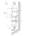
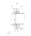
図1は、船舶に設置された排ガス処理装置100を示す図である。本例の排ガス処理装置100は、船舶のエンジン等の動力装置から排出される排ガスに含まれる硫黄酸化物(SOx)等の環境負荷物質を取り除いて、船舶外に環境負荷の比較的少ない排ガスとして排出する装置である。本例の排ガス処理装置100は、船舶における側面90および底面92の接合部近傍に設けられる。本例の排ガス処理装置100は、レデューサ部22、反応塔10および移動機構70を有する。排ガス処理装置100は、その上方において煙道部20に接続し、その下方において排水部84に接続する。なお、理解を容易にすることを目的として、図1においては、排ガス処理装置100の構成要素ではない部分に斜線を付して示す。ただし、他の図においては、排ガス処理装置100の構成要素であっても斜線を付して示す点に注意されたい。
FIG. 1 is a view showing an exhaust
本例では、反応塔10の底部14側から上部12側への高さ方向を+z方向とする。また、高さ方向とは反対の方向を−z方向とする。なお、高さ方向に平行な方向は、「±」を用いずに単にz方向と記載する。本例において、便宜的に、+z方向を「上」または「上方」と称し、−z方向を「下」または「下方」と称する場合がある。z方向は、船舶の床面に垂直な方向であってよいし、地面に垂直な方向であってもよい。ただし、z方向はこれらの方向の例に限定されない。他の例において、z方向は地面に平行な方向であってもよい。xおよびy方向は、互いに垂直である。z方向は、xおよびy方向において構成される平面に対して垂直な方向である。本例において、x、yおよびz方向は、右手系を構成する。
In this example, the height direction from the bottom 14 side to the top 12 side of the
本例の反応塔10は、上部外筒30、中部外筒40および下部外筒80を有する。下部外筒80は、中部外筒40よりも反応塔10の底部14側に位置する。下部外筒80は、側面に排ガス導入口16を有し、底部14に排水導出部17を有する。排ガス導入口16は、排ガス導入管が下部外筒80と接続する領域である。排ガス導入管は、船舶のエンジン等から排出された排ガスを反応塔10に導入する流路である。本例では、紙面奥の位置に設けられた排ガス導入口16を点線により示す。排ガスは、排ガス導入口16から反応塔10の内部へ導入される。排ガスは、反応塔10の内部で旋回上昇してよい。排ガスは、反応塔10の内部空間を+z方向に直線的に上昇するよりも内部空間を旋回する方が気液接触の確率が高くなるので、より効率的に洗浄される。
The
本例において、下部外筒80の外形には、U字ボルト82‐2が設けられる。U字ボルト82‐2の湾曲部は、下部外筒80に接触してよい。U字ボルト82‐2の長手部は、側面90に固定された台部94‐2に固定される。これにより、下部外筒80は、側面90に固定される。
In this example, a U-shaped bolt 82-2 is provided on the outer shape of the lower
反応塔10の底部14近傍は、反応塔10の内部で噴射された後に落下した液体を一時的に貯留する排水貯留部として機能してよい。排水導出部17は、下部外筒80の底部14よりもさらに−z方向に突出してよい。底部14近傍に貯留された液体は、最終的に排水導出部17から排水部84へ排出されてよい。
The vicinity of the bottom 14 of the
中部外筒40は、第1の分割体50と第2の分割体60とを有する。本例の第1の分割体50は、第2の分割体60の上方に位置する。本例の第2の分割体は、第1の分割体50の内径よりも小さな外径を有する。本例の第1の分割体50は、+z方向の端部領域に位置する固定フランジ部52と、−z方向の端部領域位置する第1のフランジ部としての移動フランジ部54とを有する。また、本例の第2の分割体60は、−z方向の端部領域位置する第2のフランジ部としての移動フランジ部64を有する。
The middle
移動機構70は、第1の分割体50および第2の分割体60のいずれかをz方向に移動する機能を有する。本例の移動機構70を利用することにより、第2の分割体60のz方向位置を固定した場合に、第1の分割体50を−z方向にスライドさせることができる。さらに、第1の分割体50のz方向位置を固定した場合に、第2の分割体60を+z方向にスライドさせることができる。ただし、図1においては、移動機構70は、第1の分割体50の移動フランジ部54と第2の分割体60の移動フランジ部64とのz方向の位置を固定している。
The moving
本例では、第1の分割体50および第2の分割体60をz方向にスライドさせて開閉するので、中部外筒40の側面を外側に回転させて開閉する場合と比較して、開閉時に必要な船内空間を減らすことができる。加えて、本例においては、中部外筒40の側面を外側に回転させて開閉する場合と比較して密封封止が容易であるので、より気密性を高くすることができる。
In this example, since the first divided
本例の排ガス処理装置100は、封止リング58を有する。封止リング58は、第2の分割体60の外径と、移動フランジ部54と、後述の封止部材56とに接触する。本例の封止リング58は、金属製のリングである。本例の封止リング58は、後述の封止部材56を圧接する。これにより、第1の分割体50と第2の分割体60との間のすき間を封止してよい。なお、本例において、封止リング58は、固定具51により移動フランジ部54に固定される。
The exhaust
上部外筒30は、中部外筒40上に設けられる。上部外筒30の外形には、U字ボルト82‐1が設けられる。U字ボルト82‐1の長手部は、台部94‐1に固定される。これにより、下部外筒80は、側面90に対して固定される。上部外筒30および下部外筒80に設けられたU字ボルト82により、反応塔10は船舶に対して固定される。
The upper
レデューサ部22は、上部外筒30上に設けられる。本例において、レデューサ部22の−z方向の端部における大径部は、上部外筒30に接続する。また、本例のレデューサ部22の+z方向の端部における小径部は、煙道部20に接続する。本例のレデューサ部22のx‐y平面における中心軸は、中部外筒40の中心軸と一致する。レデューサ部22は、x‐y平面における半径が+z方向に進むにつれて段階的に減少する円錐台形状の内部空間を有する。これにより、煙道部20と上部外筒30とが直接接続する場合と比較して、排ガス処理装置100における圧力損失を低減する機能を有する。
The
レデューサ部22は、煙道部20に接続する。煙道部20は、船舶の外まで延伸してよい。排ガス処理装置100により洗浄処理された排ガスは、煙道部20を通って船舶外へ排出されてよい。
The
本例の反応塔10は、底部14から上部12までの高さ方向の長さが3[m]であり、内径が700[mm]である。また、本例のレデューサ部22は高さ方向の長さが654[mm]であり、小径部の内径は420[mm]である。
The
図2は、図1のA‐A'上面図を示す図である。なお、図2においては、反応塔10の内部空間に位置する構造物を省略している。図2においては、移動フランジ部54上の移動機構70および固定具51を示す。本例の排ガス処理装置100は、3つの移動機構70を有する。本例の移動機構70は、中部外筒40の中心軸11から+y方向に伸びる半径軸を時計回りに±60度回転した位置および180度回転した位置に設けられる。なお、他の例において、排ガス処理装置100は、4つ以上の移動機構70を有してもよい。図2において、移動機構70は、棒部材72およびナット部77を有する。本例のナット部77は、六角柱の外形を有する。
FIG. 2 is a diagram showing a top view of AA ′ of FIG. In FIG. 2, structures located in the internal space of the
本例の排ガス処理装置100は、3つの固定具51を有する。本例の固定具51は、中心軸11から+y方向に伸びる半径軸の位置および当該半径軸を時計回りに±120度回転した位置に設けられる。本例においては、固定具51および移動機構70を中心軸11における異なる半径軸に設けることにより、固定具51および移動機構70を同じ半径軸に設ける場合と比較して、固定具51の取り付けおよび取り外しならびに移動機構70の操作がより容易になる。なお、他の例において、排ガス処理装置100は、4つ以上の固定具51を有してもよい。
The exhaust
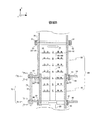
図3は、排ガス処理装置100の断面を示す図である。図3では、排ガス処理装置100の断面を示す。ただし、理解を容易にすることを目的として、幹管24、枝管25、噴射部26、液体導入部28およびバッフル29は、断面ではなく側面を示す。反応塔10は、底部14側から+z方向に延伸する内部空間15を有する。
FIG. 3 is a view showing a cross section of the exhaust
排ガス処理装置100は、下部外筒80の内部に、液体導入部28およびバッフル29を有する。本例の液体導入部28は、下部外筒80の底部14近傍において下部外筒80の側面から内部に導入される。本例の液体導入部28は、y‐z平面においてL字形状に屈曲した管である。液体導入部28には、反応塔10の外部からポンプ等を用いて、海水、湖水、川水またはアルカリ性の液体が導入される。本例の液体は、排ガスを処理する液体である。液体導入部28と幹管24とは流体連結されており、液体導入部28に導入された液体は幹管24へ供給される。
The exhaust
本例のバッフル29は、液体導入部28に設置される。バッフル29は、x‐y平面に平行な平面を有してよい。本例のバッフル29は、液体導入部28が通ることができる貫通開口を有する円板である。バッフル29は、排ガス導入口16よりも底部14側に設けられる。バッフル29は、排ガスが導入される領域と排水を貯留する領域とに、下部外筒80を区切る機能を有してよい。
The
排ガス処理装置100は、反応塔10の内部空間15において、幹管24、複数の枝管25および複数の噴射部26を有する。本例の幹管24は、反応塔10の内部空間15において高さ方向に延伸する。本例の幹管24は、中部外筒40と同じ高さ位置に設けられる。幹管24は、液体導入部28から供給された液体を高さ方向に運搬可能である。幹管24には複数の枝管25が接続される。幹管24から複数の枝管25へ液体が供給されるよう、幹管24と複数の枝管25とは流体連結されている。
The exhaust
本例の幹管24は、高さ方向範囲において分割することできない1本の管である。ただし、他の例において、幹管24は、高さ方向において二以上に分割可能であってもよい。一例において、幹管24の高さ方向における長さの半分の位置で、幹管24は二つに分割可能であってよい。これにより、第1の分割体50を開いた場合には、幹管24の上半分を反応塔10から取り出すことができる。さらに、第2の分割体60を開いた場合には、幹管24の下半分を反応塔10から取り出すことができる。
The
複数の枝管25は、幹管24の外壁から中部外筒40の内壁に向けて延伸して設けられる。枝管25の長手方向の一端は、幹管24に溶接されてよい。本例では、同じ高さ位置に4つの枝管25‐A、枝管25‐B、枝管25‐Cおよび枝管25‐Dが設けられる。本例において、4つの枝管25‐Aから枝管25‐Dは、幹管24を上面視した場合に略十字形状を形成する。なお、図3においては紙面奥に位置する枝管25‐Dは図示されていない。
The plurality of
本例において複数の枝管25は、高さ方向において重なるよう設けられる。本例において、複数の枝管25‐1Aから25‐nAは、高さ方向において一定間隔で離間して各々異なる高さ位置に設けられる。なお、nは2以上の自然数である。本例においては、n=7である。枝管25の高さ方向におけるピッチは0.3[m]であってよい。本例において、枝管25‐1Bから枝管25‐nBも、各々異なる高さ位置に所定のピッチだけ離間して設けられる。枝管25‐1Cから枝管25‐nCおよび枝管25‐1Dから枝管25‐nDも同様である。
In this example, the plurality of
複数の枝管25の各々は、噴射部26を有する。本例では、1つの枝管25は2つの噴射部26を有する。なお、1つの枝管25が有する噴射部26の数は、2つに限定されず3つ以上であってもよい。噴射部26は、ねじ込み手段により枝管25に接続されてよく、溶接により枝管25に接続されてもよい。
Each of the plurality of
噴射部26は、幹管24から供給される液体を反応塔10の内部空間15において噴射する。噴射された液体は、細かい水滴または霧状に変化する。噴射された液体と排ガスとを気液接触させることにより、排ガス中の硫黄酸化物等は液体に吸収される。これにより、排ガスを洗浄することができる。噴射部26は、空円錐状に液体を噴射するスプレーノズルであってよい。本例では、×印を付した部分に、噴射部26の噴射口が設けられる。
The
本例の第1の分割体50は、円筒状の側面の端部を移動フランジ部54にはめ合わせることにより組み立てられる。具体的には、円筒状の側面の底部に位置する凸部を移動フランジ部54の上面の凹部に嵌合させることにより、側面および移動フランジ部54における円の中心を正確に位置合わせして組み立てる。当該組み立て方式は、一般的にインロー方式と呼ばれている。本例の第2の分割体60も、インロー方式により組み立てられる。
The first divided
本例の排ガス処理装置100は、封止部材56をさらに有する。本例の封止部材56は、第2の分割体60の外径と、移動フランジ部54の底部14側の面と、封止リング58の内側の斜面57とに接触する。本例の封止部材56は、Oリングである。封止リング58の内側の斜面57が封止部材56を圧接することにより、第1の分割体50と第2の分割体60との間のすき間を封止することができる。
The exhaust
移動機構70は、棒部材72および駆動部76を有する。1つの移動機構70は、1つの棒部材72と、棒部材72の異なる位置にそれぞれ設けられた2つの駆動部76とを有する。棒部材72は、移動フランジ部54と移動フランジ部64とを連結する。駆動部76は、第1の分割体50および第2の分割体60のいずれかをz方向に移動させる。本例において、駆動部76‐1は、第1の分割体50を±z方向に移動させる。また、駆動部76‐2は、第2の分割体60を±z方向に移動させる。
The moving
上部外筒30は、内部に液返しリング35を有する。液返しリング35は、上部外筒30の内壁に接してリング状に設けられる。液返しリング35は、霧状となった液体が排ガス処理装置100の外に排出されることを防ぐ機能を有してよい。液返しリング35は、リング上に滞留した液体が自重により下方に落下できる開口を有してよい。
The upper
図4は、第1実施形態における領域Bの拡大図を示す図である。本例において、中部外筒40を閉じた状態においてz方向において連結される移動フランジ部54と移動フランジ部64とは、ともに−z方向の端部領域に位置する。本例において、移動フランジ部54は第1の分割体50の最も下方に設けられ、移動フランジ部64は第2の分割体60の最も下方に設けられる。本例において、移動フランジ部54の外径は、固定フランジ部52の外径よりも長い。また、第2の分割体60は、固定フランジ部を有せず、移動フランジ部64のみを有する。移動フランジ部64は、移動フランジ部54の外径と同程度の長さの外径を有する。
FIG. 4 is an enlarged view of the region B in the first embodiment. In this example, both the moving
本例において、固定フランジ部という語は、常にその位置が固定されているフランジ部を意味しない。本例において、固定フランジ部52は、第1の分割体50が移動する際には移動してよい。本例において、固定フランジ部は、駆動部76が位置する移動フランジ部とは異なるフランジ部であることを意味するに過ぎない。
In this example, the term fixed flange portion does not mean a flange portion whose position is always fixed. In this example, the fixed
本例において、棒部材72のz方向における長さは、中部外筒40を閉じた状態において、z方向において連結された移動フランジ部54と移動フランジ部64との間の長さよりも長い。具体的には、中部外筒40を閉じた状態において、本例の棒部材72は、移動フランジ部54よりも上に突出し、移動フランジ部64よりも下に突出する。棒部材72は、第2の分割体60のz方向長さより長くてもよい。また、本例の棒部材72は、2つのナット部77のz方向長さ分だけ移動フランジ部54よりも上に突出してよく、2つのナット部77のz方向長さ分だけ移動フランジ部64よりも下に突出してよい。
In this example, the length in the z direction of the
本例の棒部材72は、ねじ切りされた表面73を有する。また、本例の駆動部76は、複数のナット部77を有する。本例の駆動部76‐1は、固定用のナット部77‐1および移動用のナット部77‐2を有する。本例では、ねじ切りされた表面73を有する棒部材72と複数のナット部77とにより移動機構70を構成する。それゆえ、移動機構70の構成を簡単にできる。
The
固定用のナット部77‐1と移動用のナット部77‐2とは、移動フランジ部54を間に挟む。移動用のナット部77‐2は、移動フランジ部54に接触して、第1の分割体50を下から支えることができる。移動用のナット部77‐2は、棒部材72においてz方向に移動可能である。固定具31を外した後に移動用のナット部77‐2を−z方向に回転移動させることにより、第1の分割体50を−z方向に移動させることができる。なお、第1の分割体50を−z方向に移動させる際に、固定用のナット部77‐1を外してもよい。また、なお、第1の分割体50を−z方向に移動させる際に、固定具51、封止部材56および封止リング58は、中部外筒40から外してよいし、中部外筒40から外さずにそのままにしてもよい。
The fixing nut portion 77-1 and the moving nut portion 77-2 sandwich the moving
また、本例の駆動部76‐2は、固定用のナット部77‐3および移動用のナット部77‐4を有する。固定用のナット部77‐3と移動用のナット部77‐4とは、移動フランジ部64を間に挟む。移動用のナット部77‐4は、移動フランジ部64に接触して、第2の分割体60を下から支えることができる。移動用のナット部77‐4は、棒部材72においてz方向に移動可能である。固定具61を外した後に移動用のナット部77‐4を+z方向に回転移動させることにより、第2の分割体60を+z方向に移動させることができる。なお、第2の分割体60を+z方向に移動させる際には、固定用のナット部77‐1を外す。また、なお、第2の分割体60を+z方向に移動させる際に、固定具51、封止部材56および封止リング58は、中部外筒40から外してよいし、中部外筒40から外さずにそのままにしてもよい。
Further, the drive unit 76-2 of the present example includes a fixing nut portion 77-3 and a moving nut portion 77-4. The fixing nut portion 77-3 and the moving nut portion 77-4 sandwich the moving
これにより、排ガスを処理する位置に反応塔10を設置した状態において、中部外筒40の少なくとも一部はz方向に移動可能である。本例において、排ガスを処理する位置に反応塔10を設置した状態とは、排ガス処理装置100が上方において煙道部20に接続し、かつ、下方において排水部84に接続した状態をいう。本例においては、噴射部26をメンテナンスする際に、クレーン等を用いて反応塔10を取り外す必要が無いので、クレーンを設置するスペースおよびクレーンを設けるコストを削減することができる。また、クレーン等による作業を要しないので、その分メンテナンス作業時間を短縮することができる。
Thereby, in the state which installed the
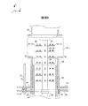
図5Aは、第1の分割体50を−z方向に移動した状態を示す図である。移動用のナット部77‐2を−z方向に最大限移動させることにより、第1の分割体50に対応する高さ範囲に略対応する内部空間15‐1が露出する。これにより作業者は、内部空間15‐1に位置する噴射部26をメンテナンスすることができる。本例においては、枝管25‐1から枝管25‐4まで(即ち、第1段目から第4段目まで)の噴射部26をメンテナンスすることができる。なお、本例において、メンテナンスとは、噴射部26の噴射性能を維持するために、噴射部26を交換することおよび噴射部26をクリーニングすること等の作業をいう。
FIG. 5A is a diagram illustrating a state in which the first divided
なお、移動用のナット部77‐2を回転移動させる際には、3つの移動用のナット部77‐2の内1つの移動用のナット部77‐2だけを集中的に回転移動させずに、3つの移動用のナット部77‐2を少しずつ回転移動させる方がよい。一例として、3つのナット部77‐2をそれぞれ一回転ずつ回転移動させる。これにより、移動用のナット部77‐2と棒部材72との間に摩擦熱が発生して移動用のナット部77‐2が棒部材72に対して動かなくなること(かじり(焼き付き))を防止することができる。なお、反応塔10はU字ボルト82によりz方向の位置が固定されているので、第1の分割体50を上部外筒30から離間させても内部空間15‐1の露出は維持される。
When rotating the moving nut part 77-2, only one moving nut part 77-2 of the three moving nut parts 77-2 is not rotatively moved. It is better to rotate and move the three moving nut portions 77-2 little by little. As an example, the three nut portions 77-2 are rotationally moved by one rotation each. As a result, frictional heat is generated between the moving nut portion 77-2 and the
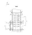
図5Bは、第2の分割体60を+z方向に移動した状態を示す図である。移動用のナット部77‐4を+z方向に最大限移動させることにより、第2の分割体60に対応する高さ範囲に略対応する内部空間15‐2が露出する。これにより作業者は、内部空間15‐2に位置する噴射部26をメンテナンスすることができる。本例においては、枝管25‐5から枝管25‐7まで(即ち、第5段目から第7段目まで)の噴射部26をメンテナンスすることができる。
FIG. 5B is a diagram illustrating a state in which the second divided
図6は、第1実施形態の変形例を示す図である。本例の移動機構70において、駆動部76は、ボールブッシュ部78を有する。また、棒部材72は、ボールブッシュ部78のボールを受けるスパイラル状の溝を表面74に有する。係る点において、図1から図5Aおよび図5Bの例と異なる。なお、一般的に、ボールブッシュはリニアブッシュと呼ばれる場合もある。
FIG. 6 is a diagram illustrating a modification of the first embodiment. In the moving
本例のボールブッシュ部78‐1は、移動フランジ部54に接触して、第1の分割体50を支えることができる。同様に、本例のボールブッシュ部78‐2は、移動フランジ部64に接触して、第2の分割体60を支えることができる。また、本例のボールブッシュ部78‐1およびボールブッシュ部78‐2は、棒部材72においてz方向に移動可能である。具体的には、ボールブッシュ部78は、棒部材72に対して回転することにより±z方向に移動することができる。
The ball bush portion 78-1 in this example can support the first divided
ボールブッシュ部78は、電動で回転移動する機構を有してよい。この場合、3つのボールブッシュ部78は同時に同じピッチで移動することができる。これにより、ナット部77の例と比較して、第1の分割体50または第2の分割体60を方向に正確に移動させることができる。また、ナット部77の例と比較して、より短時間で第1の分割体50または第2の分割体60を移動させることができる。
The ball bushing 78 may have a mechanism that rotates and moves electrically. In this case, the three ball bush portions 78 can move simultaneously at the same pitch. Thereby, compared with the example of the
図7は、第2の分割体60の変形例を示す部分拡大図である。図7においては、理解を容易にするべく、幹管24、枝管25および噴射部26を省略する。本例において、移動フランジ部64が設けられた端部領域とは反対側の端部領域において、第2の分割体60の内径65は外径66よりも長い。つまり、本例において、第2の分割体60の+z方向の端部は、第1の分割体50の内表面に対向する斜面67を有する。図7の断面視図において、第2の分割体60の内表面(つまり、内径の円筒)と斜面67とは、30度の角度を形成してよい。これにより、第1の分割体50および第2の分割体60は、斜面67を設けない場合と比較して互いにスライドしやすくなる。なお、図7の例を第1実施形態およびその変形例に適用してよい。
FIG. 7 is a partially enlarged view showing a modification of the second divided
図8は、第2実施形態における領域Bの拡大図を示す図である。本例において、第2の分割体60は第1の分割体50よりも+z方向に設けられる。これに伴い、中部外筒40を閉じた状態においてz方向において連結される移動フランジ部54と移動フランジ部64とは、ともに+z方向の端部領域に位置する。本例において、移動フランジ部54は第1の分割体50の最も上方に設けられ、移動フランジ部64は第2の分割体60の最も上方に設けられる。つまり、本例は、第1実施形態の中部外筒40を上下逆さまにした構成に相当する。
FIG. 8 is an enlarged view of the region B in the second embodiment. In this example, the second divided
本例では、第1の分割体50の内径よりも小さな外径を有する第2の分割体60を、第1の分割体50よりも上に設ける。これにより、第1実施形態と比較して、内部空間15の液体が中部外筒40から漏れにくいという点が有利である。なお、本例においても、封止リング58の斜面57は、第2の分割体60の外径と、移動フランジ部54と、封止部材56とに接触する。また、なお、本例においても、図6におけるボールブッシュ部78の例および図7における斜面67を設ける例の一以上を適用してよい。
In this example, the second divided
図9は、第3実施形態における領域Bの拡大図を示す図である。本例の第1の分割体50は、第1実施形態における第1の分割体50を上下逆さまにした構成に相当する。本例において、中部外筒40を閉じた状態において、移動フランジ部54と移動フランジ部64とは、z方向において連結される。特に、本例では、移動フランジ部54が+z方向の端部領域に位置し、移動フランジ部64が−z方向の端部領域に位置する。また、本例では、棒部材72のz方向における長さは、中部外筒40を閉じた状態において、z方向において連結された移動フランジ部54と移動フランジ部54との間の長さよりも長い。
FIG. 9 is an enlarged view of the region B in the third embodiment. The
本例の棒部材72は、第1および第2実施形態の棒部材72よりも長い距離に渡って、第1の分割体50および第2の分割体60を支持する。それゆえ、本例においては、第1および第2実施形態と比較して、中部外筒40の機械的安定性が高いという点が有利である。
The
なお、本例の排ガス処理装置100は、第2の分割体60の外径と、移動フランジ部54とは反対方向の端部領域に位置する第3のフランジ部としての固定フランジ部52とに少なくとも接触する封止部材56を有する。封止リング58の斜面57は、第2の分割体60の外径と、固定フランジ部52と、封止部材56とに接触する。なお、固定フランジ部52は、第1の分割体50において移動フランジ部54とは反対方向の端部領域に位置する。また、なお、本例においても、図6におけるボールブッシュ部78の例および図7における斜面67を設ける例の一以上を適用してよい。
In addition, the exhaust
図10は、第4実施形態における領域Bの拡大図を示す図である。本例では、中部外筒40を閉じた状態において、移動フランジ部54が−z方向の端部領域に位置し、移動フランジ部64が+z方向の端部領域に位置する。つまり、本例は、第3実施形態の中部外筒40を上下逆さまにした構成に相当する。本例においても、第1および第2実施形態と比較して、中部外筒40の機械的安定性が高い。なお、本例においても、封止リング58の斜面57は、第2の分割体60の外径と、固定フランジ部52と、封止部材56とに接触する。また、なお、本例においても、図6におけるボールブッシュ部78の例および図7における斜面67を設ける例の一以上を適用してよい。
FIG. 10 is an enlarged view of the region B in the fourth embodiment. In this example, in a state where the middle
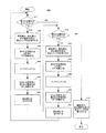
図11は、排ガス処理装置100のメンテナンス方法200を示す図である。メンテナンス時においては、エンジン等から反応塔10への排ガスの供給を停止する。加えて、幹管24から噴射部26への液体の供給も停止する。
FIG. 11 is a diagram illustrating a
メンテナンス方法200は上述の第1および第3実施形態に適用してよい。本例では、排ガスを処理する位置に反応塔10を設置した状態において、各段階を実行することができる。本例では、第1の分割体50と同じ高さ位置の噴射部26をメンテナンスするか否かを最初に判断する(S10)。S10においてYESの場合S20に進み、S10においてNOの場合S12に進む。
The
S20は、固定具31、固定具51、封止部材56および封止リング58を反応塔10から取り外す段階である。また、S20において、ナット部77を用いる例にあっては、固定用ナット部77‐3を+z方向に移動させてよい。なお、ナット部77を用いる例においては、S20において固定用のナット部77‐1を反応塔10から取り外してもよい。
S20 is a stage in which the
S30は、反応塔10の中部外筒40の少なくとも一部をz方向に平行に移動する段階である。第1および第3実施形態においては、第1の分割体50を−z方向に移動させる。
S30 is a stage in which at least a part of the middle
S40は、第1の分割体50に略対応する内部空間15を露出して、反応塔10の内部に位置する噴射部26をメンテナンスする段階である。内部空間15が露出されるので、作業者は容易に噴射部26にアクセスすることができる。
S <b> 40 is a stage in which the
S50は、S30とは逆方向に、第1の分割体50を平行移動させる段階である。本例においては、S30において−z方向に移動させた第1の分割体50を+z方向に移動させる段階である。これにより、中部外筒40を閉じる。S60は、固定具31を取り付ける段階である。これにより、第1の分割体50を上部外筒30に固定する。
S50 is a step of translating the first divided
次にS12に進む。S12は、第2の分割体60と同じ高さ位置の噴射部26をメンテナンスするか否かを判断する段階である。S12においてYESの場合、S22に進む。S12においてNOの場合、S70に進む。
Next, the process proceeds to S12. S12 is a stage in which it is determined whether or not the
S22からS62の一連の段階は、S20からS60の一連の段階とほぼ同様であるので、相違点のみを述べる。S22では、固定具31に代えて固定具61を取り外す。また、ナット部77を用いる例においては、S22において固定用のナット部77‐3を移動させる。係る点において、S22はS20と異なる。
Since the series of steps S22 to S62 is almost the same as the series of steps S20 to S60, only the differences will be described. In S22, the
S32からS52の一連の段階は、第1の分割体50に代えて第2の分割体60を移動させる。係る点において、S32からS52の一連の段階は、S30からS50の一連の段階と異なる。S62は、固定具61を取り付ける段階である。これにより、第2の分割体60を下部外筒80に固定する。
In a series of steps S32 to S52, the second divided
次にS10に戻る。第1の分割体50と同じ高さ位置の噴射部26を既にメンテナンスした場合には、S10においてNOを選択して、S12に進んでよい。第2の分割体60と同じ高さ位置の噴射部26を既にメンテナンスした場合には、S12においてNOを選択して、S70に進んでよい。
Next, the process returns to S10. When the
S70は、固定具51、封止部材56および封止リング58を反応塔10に取りつける段階である。S70の後、メンテナンス方法200のフローは終了する。
S <b> 70 is a stage in which the
なお、本例のメンテナンス方法200においては、第1の分割体50をメンテナンスするか否かを最初に判断するが、第2の分割体60をメンテナンスするか否かを最初に判断してもよい。つまり、S10からS60の一連の段階を、S12からS62の一連の段階と入れ替えてもよい。
In the
図12は、排ガス処理装置100のメンテナンス方法210を示す図である。メンテナンス方法210は上述の第2および第4実施形態に適用してよい。図12のメンテナンス方法210は、図11のメンテナンス方法200とほぼ同じである。相違点は、次の(1)から(3)である。これら以外の、重複する説明は省略する。
FIG. 12 is a diagram illustrating a
(1)図12のS14からS64における一連の段階が第2の分割体60を対象としているのに対して、図11のS10からS60における一連の段階が第1の分割体50を対象としている。(2)図12のS16からS66における一連の段階が第1の分割体50を対象としているのに対して、図11のS12からS62における一連の段階が第2の分割体60を対象としている。(3)S72において、封止部材56、封止リング58および固定具61を反応塔10に取り付ける。
(1) While the series of steps in S14 to S64 in FIG. 12 is for the second divided
図13Aは、第5実施形態における領域Bの拡大図を示す図である。第5から第7実施形態は、移動機構70により中部外筒40の一部をスライド開閉する上述の例の代替例である。第5から第7実施形態において、中部外筒40の一部は伸縮性筒部を有してよい。
FIG. 13A is an enlarged view of a region B in the fifth embodiment. The fifth to seventh embodiments are alternative examples of the above-described example in which a part of the middle
本例の中部外筒40は、上部分割体150と下部分割体160とを有する。本例の上部分割体150は、上部フランジ部152と、下部フランジ部154と、上部フランジ部152と下部フランジ部154との間のベローズ(bellows)部156とを有する。ベローズ部156は、z方向に伸縮性筒部である。また、本例の下部分割体160は、上部フランジ部162と、下部フランジ部164とを有する。下部フランジ部154と上部フランジ部162とは、固定具151により固定される。下部フランジ部164と下部外筒80と上部とは、固定具161により固定される。
The middle
図13Bは、ベローズ部156を開いた状態を示す図である。ベローズ部156は、リング状の薄肉金属板の内縁と外縁とを交互に溶接してつなぎ合わせた伸縮性筒部である。固定具31を取り外すことにより、作業者は手動でベローズ部156を開けることができる。これにより、第1の分割体50に対応する高さ範囲に略対応する内部空間15‐1が露出する。したがって、作業者は、上部分割体150と同じ高さ位置の噴射部26をメンテナンスすることができる。本例においては、枝管25‐1から枝管25‐4まで(即ち、第1段目から第4段目まで)の噴射部26をメンテナンスすることができる。ベローズ部156を用いることにより、第1から第4実施形態と比較して上部分割体150の開閉がより容易になる点が有利である。
FIG. 13B is a diagram illustrating a state in which the
図14は、図13AのC‐C'上面図を示す図である。なお、図14においては、内部空間15の構造を省略している。図14においては、下部フランジ部154上の固定具151を示す。本例の排ガス処理装置100は、6つの固定具151を有する。本例の固定具151は、中部外筒40の中心軸11から+y方向に伸びる半径軸を時計回りに±60度回転した位置、±120度回転した位置、ならびに、0度および180度回転した位置に設けられる。
14 is a diagram showing a top view of CC ′ of FIG. 13A. In FIG. 14, the structure of the
図15は、第6実施形態における領域Bの拡大図を示す図である。本例においては、下部分割体160が、上部フランジ部162と下部フランジ部164との間のベローズ部166を有する。固定具151を取り外すことにより、作業者は手動でベローズ部166を開けることができる。これにより、下部分割体160と同じ高さ位置の噴射部26をメンテナンスすることができる。本例においては、第1から第4実施形態と比較して下部分割体160の開閉がより容易になる点が有利である。
FIG. 15 is an enlarged view of the region B in the sixth embodiment. In this example, the lower divided
図16は、第7実施形態における領域Bの拡大図を示す図である。本例においては、上部フランジ部172および下部フランジ部174を除く中部外筒40の全体がベローズ部176である。本例では固定具31を取り外すことにより、作業者は手動でベローズ部176を開けることができる。これにより、中部外筒40と同じ高さ位置の噴射部26をメンテナンスすることができる。本例においては、第1から第4実施形態と比較して、中部外筒40全体の開閉がより容易になる点が有利である。
FIG. 16 is an enlarged view of a region B in the seventh embodiment. In this example, the entire middle
以上、本発明を実施の形態を用いて説明したが、本発明の技術的範囲は上記実施の形態に記載の範囲には限定されない。上記実施の形態に、多様な変更又は改良を加えることが可能であることが当業者に明らかである。その様な変更又は改良を加えた形態も本発明の技術的範囲に含まれ得ることが、特許請求の範囲の記載から明らかである。 As mentioned above, although this invention was demonstrated using embodiment, the technical scope of this invention is not limited to the range as described in the said embodiment. It will be apparent to those skilled in the art that various modifications or improvements can be added to the above embodiment. It is apparent from the description of the scope of claims that embodiments with such changes or improvements can be included in the technical scope of the present invention.
特許請求の範囲、明細書、および図面中において示した装置、システム、プログラム、および方法における動作、手順、ステップ、および段階等の各処理の実行順序は、特段「より前に」、「先立って」等と明示しておらず、また、前の処理の出力を後の処理で用いるのでない限り、任意の順序で実現しうることに留意すべきである。特許請求の範囲、明細書、および図面中の動作フローに関して、便宜上「まず、」、「次に、」等を用いて説明したとしても、この順序で実施することが必須であることを意味するものではない。 The order of execution of each process such as operations, procedures, steps, and stages in the apparatus, system, program, and method shown in the claims, the description, and the drawings is particularly “before” or “prior to”. It should be noted that the output can be realized in any order unless the output of the previous process is used in the subsequent process. Even if the operation flow in the claims, the description, and the drawings is described using “first”, “next”, etc. for convenience, it means that it is essential to carry out in this order. It is not a thing.
10・・反応塔、11・・中心軸、12・・上部、14・・底部、15・・内部空間、16・・排ガス導入口、17・・排水導出部、20・・煙道部、22・・レデューサ部、24・・幹管、25・・枝管、26・・噴射部、28・・液体導入部、29・・バッフル、30・・上部外筒、31・・固定具、35・・液返しリング、40・・中部外筒、50・・第1の分割体、51・・固定具、52・・固定フランジ部、54・・移動フランジ部、56・・封止部材、57・・斜面、58・・封止リング、60・・第2の分割体、61・・固定具、64・・移動フランジ部、65・・内径、66・・外径、67・・斜面、70・・移動機構、72・・棒部材、73・・表面、74・・表面、76・・駆動部、77・・ナット部、78・・ボールブッシュ部、80・・下部外筒、82・・U字ボルト、84・・排水部、90・・側面、92・・底面、94・・台部、100・・排ガス処理装置、150・・上部分割体、151・・固定具、152・・上部フランジ部、154・・下部フランジ部、156・・ベローズ部、160・・下部分割体、161・・固定具、162・・上部フランジ部、164・・下部フランジ部、166・・ベローズ部、172・・上部フランジ部、174・・下部フランジ部、176・・ベローズ部、200・・メンテナンス方法、210・・メンテナンス方法 10 .... Reaction tower, 11 .... Central axis, 12 .... Top, 14 .... Bottom, 15 .... Internal space, 16 .... Exhaust gas inlet, 17 .... Drain discharge part, 20 .... Smoke part, 22 .. Reducer section, 24 .. Trunk pipe, 25 .. Branch pipe, 26 .. Injection section, 28 .. Liquid introduction section, 29 .. Baffle, 30 .. Upper outer cylinder, 31.・ Liquid return ring, 40 ・ ・ Central outer cylinder, 50 ・ ・ First divided body, 51 ・ ・ Fixing tool, 52 ・ ・ Fixing flange, 54 ・ ・ Moving flange, 56 ・ ・ Sealing member, 57 ・..Slope, 58..Seal ring, 60..Second divided body, 61..Fixture, 64..Moving flange, 65..Inner diameter, 66..Outer diameter, 67..Slope, 70. · Moving mechanism, 72 ·· Bar member, 73 ·· Surface, 74 · · Surface, 76 · · Drive portion, 77 · · Nut portion, 78 · · Ball Cushion part, 80 ... Lower outer cylinder, 82 ... U-bolt, 84 ... Drainage part, 90 ... Side, 92 ... Bottom, 94 ... Deck, 100 ... Exhaust gas treatment device, 150 ... Upper Divided body, 151 .. Fixing part, 152 .. Upper flange part, 154 .. Lower flange part, 156 .. Bellows part, 160 .. Lower divided part, 161 .. Fixing part, 162 .. Upper flange part, 164 ..Lower flange portion, 166 ..Bellows portion, 172 ..Upper flange portion, 174 ..Lower flange portion, 176 ..Bellows portion, 200 ..Maintenance method, 210 ..Maintenance method
Claims (14)
前記反応塔は外筒を有し、
排ガスを処理する位置に前記反応塔を設置した状態において、前記外筒の少なくとも一部は前記高さ方向と平行な方向に移動可能である
排ガス処理装置。 An exhaust gas treatment apparatus comprising a reaction tower having an internal space extending in a height direction to an upper side from which exhaust gas treated from the bottom side into which exhaust gas is introduced is discharged,
The reaction tower has an outer cylinder,
In the state which installed the said reaction tower in the position which processes exhaust gas, the exhaust gas processing apparatus which can move to the direction parallel to the said height direction at least one part of the said outer cylinder.
第1の分割体と、
前記第1の分割体の内径よりも小さな外径を有する第2の分割体と
を有し、
前記第1の分割体および前記第2の分割体のいずれかを前記高さ方向と平行な方向に移動する移動機構をさらに備える
請求項1に記載の排ガス処理装置。 The outer cylinder is
A first divided body;
A second divided body having an outer diameter smaller than the inner diameter of the first divided body,
The exhaust gas treatment apparatus according to claim 1, further comprising a moving mechanism that moves either the first divided body or the second divided body in a direction parallel to the height direction.
請求項2に記載の排ガス処理装置。 The exhaust gas treatment apparatus according to claim 2, wherein the second divided body is provided in the height direction with respect to the first divided body.
前記第1の分割体において前記高さ方向と平行な方向における端部領域に位置する第1のフランジ部と、前記第2の分割体において前記高さ方向と平行な方向における端部領域に位置する第2のフランジ部とを連結する棒部材と、
前記第1の分割体および前記第2の分割体のいずれかを前記高さ方向と平行な方向に移動させる駆動部と
を有する
請求項2または3に記載の排ガス処理装置。 The moving mechanism is
A first flange portion located in an end region in a direction parallel to the height direction in the first divided body, and an end region in a direction parallel to the height direction in the second divided body; A rod member that connects the second flange portion to
4. The exhaust gas treatment apparatus according to claim 2, further comprising: a driving unit configured to move either the first divided body or the second divided body in a direction parallel to the height direction.
前記駆動部は、前記棒部材において前記高さ方向と平行な方向に移動可能であり、前記第1のフランジ部および前記第2のフランジ部のいずれかに接触して、前記第1の分割体および前記第2の分割体のいずれかを支えることができるナット部を有する
請求項4に記載の排ガス処理装置。 The bar member has a threaded surface;
The drive unit is movable in the bar member in a direction parallel to the height direction, and is in contact with either the first flange portion or the second flange portion, and the first divided body. The exhaust gas treatment apparatus according to claim 4, further comprising a nut portion capable of supporting any one of the second divided bodies.
前記駆動部は、前記棒部材において前記高さ方向と平行な方向に移動可能であり、前記第1のフランジ部および前記第2のフランジ部のいずれかに接触して、前記第1の分割体および前記第2の分割体のいずれかを支えることができるボールブッシュ部を有する
請求項4に記載の排ガス処理装置。 The bar member has a spiral groove on the surface,
The drive unit is movable in the bar member in a direction parallel to the height direction, and is in contact with either the first flange portion or the second flange portion, and the first divided body. The exhaust gas treatment apparatus according to claim 4, further comprising a ball bush portion capable of supporting any of the second divided bodies.
請求項4から6のいずれか一項に記載の排ガス処理装置。 7. The inner diameter of the second divided body is longer than the outer diameter in the end region opposite to the end region where the second flange portion is provided. 7. Exhaust gas treatment equipment.
前記棒部材の前記高さ方向における長さは、前記外筒を閉じた状態において、前記高さ方向において連結された前記第1のフランジ部と前記第2のフランジ部との間の長さよりも長い
請求項4から7のいずれか一項に記載の排ガス処理装置。 Both the first flange portion of the first divided body and the second flange portion of the second divided body connected in the height direction in a state where the outer cylinder is closed are both at the height. Located in the end region in the direction opposite to the direction or the height direction,
The length of the rod member in the height direction is greater than the length between the first flange portion and the second flange portion connected in the height direction in a state where the outer cylinder is closed. The exhaust gas treatment apparatus according to any one of claims 4 to 7, which is long.
前記棒部材の前記高さ方向における長さは、前記外筒を閉じた状態において、前記高さ方向において連結された前記第1のフランジ部と前記第2のフランジ部との間の長さよりも長い
請求項4から7のいずれか一項に記載の排ガス処理装置。 One of the first flange portion of the first divided body and the second flange portion of the second divided body, which are connected in the height direction in a state where the outer cylinder is closed, is the high height. Located in the end region in the vertical direction, the other is located in the end region in the direction opposite to the height direction,
The length of the rod member in the height direction is greater than the length between the first flange portion and the second flange portion connected in the height direction in a state where the outer cylinder is closed. The exhaust gas treatment apparatus according to any one of claims 4 to 7, which is long.
前記第2の分割体の前記外径と、前記第1の分割体の前記第1のフランジ部と、前記封止部材とに接触する封止リングと
をさらに有する
請求項8に記載の排ガス処理装置。 At least a sealing member that contacts the outer diameter of the second divided body and the first flange portion of the first divided body;
The exhaust gas treatment according to claim 8, further comprising: a sealing ring that contacts the outer diameter of the second divided body, the first flange portion of the first divided body, and the sealing member. apparatus.
前記第2の分割体の前記外径と、前記第1の分割体の前記第3のフランジ部と、前記封止部材とに接触する封止リングと
をさらに有する
請求項9に記載の排ガス処理装置。 A sealing member that contacts at least the outer diameter of the second divided body and a third flange portion located in an end region opposite to the first flange portion of the first divided body. When,
The exhaust gas treatment according to claim 9, further comprising a sealing ring that contacts the outer diameter of the second divided body, the third flange portion of the first divided body, and the sealing member. apparatus.
請求項1に記載の排ガス処理装置。 The exhaust gas treatment apparatus according to claim 1, wherein at least a part of the outer cylinder has a stretchable cylinder portion.
前記幹管は、前記高さ方向において二以上に分割可能である
請求項1から12のいずれか一項に記載の前記排ガス処理装置。 In the internal space of the reaction tower, further comprising a trunk pipe capable of transporting a liquid for treating exhaust gas in the height direction,
The exhaust gas treatment apparatus according to any one of claims 1 to 12, wherein the trunk pipe can be divided into two or more in the height direction.
排ガスを処理する位置に前記反応塔を設置した状態において、前記反応塔の外筒の少なくとも一部を前記反応塔の高さ方向と平行な方向に平行に移動する段階と、
前記移動する段階の後に、前記反応塔の内部をメンテナンスする段階と
を備える
排ガス処理装置をメンテナンスする方法。 In the exhaust gas treatment apparatus comprising a reaction tower having an internal space extending in the height direction to the upper side from which exhaust gas treated from the bottom side into which exhaust gas is introduced is discharged, a method of maintaining the exhaust gas treatment apparatus,
In a state where the reaction tower is installed at a position where exhaust gas is treated, moving at least a part of the outer cylinder of the reaction tower in a direction parallel to the height direction of the reaction tower;
A method of maintaining an exhaust gas treatment apparatus comprising the step of maintaining the inside of the reaction tower after the moving step.
Priority Applications (2)
| Application Number | Priority Date | Filing Date | Title |
|---|---|---|---|
| JP2016104641A JP2017209629A (en) | 2016-05-25 | 2016-05-25 | Exhaust gas processing device and method for conducting maintenance of the same |
| PCT/JP2017/013737 WO2017203836A1 (en) | 2016-05-25 | 2017-03-31 | Exhaust gas treatment device and maintenance method for exhaust gas treatment device |
Applications Claiming Priority (1)
| Application Number | Priority Date | Filing Date | Title |
|---|---|---|---|
| JP2016104641A JP2017209629A (en) | 2016-05-25 | 2016-05-25 | Exhaust gas processing device and method for conducting maintenance of the same |
Publications (1)
| Publication Number | Publication Date |
|---|---|
| JP2017209629A true JP2017209629A (en) | 2017-11-30 |
Family
ID=60412807
Family Applications (1)
| Application Number | Title | Priority Date | Filing Date |
|---|---|---|---|
| JP2016104641A Pending JP2017209629A (en) | 2016-05-25 | 2016-05-25 | Exhaust gas processing device and method for conducting maintenance of the same |
Country Status (2)
| Country | Link |
|---|---|
| JP (1) | JP2017209629A (en) |
| WO (1) | WO2017203836A1 (en) |
Family Cites Families (7)
| Publication number | Priority date | Publication date | Assignee | Title |
|---|---|---|---|---|
| JPS49112230A (en) * | 1973-02-28 | 1974-10-25 | ||
| JPS55111531U (en) * | 1979-01-31 | 1980-08-05 | ||
| JPS6319490A (en) * | 1986-07-07 | 1988-01-27 | 新日本製鐵株式会社 | Detachable device for gas duct |
| JPH0451847Y2 (en) * | 1988-06-03 | 1992-12-07 | ||
| JP3631881B2 (en) * | 1997-05-14 | 2005-03-23 | 株式会社東洋製作所 | Photocatalyst fluid circulation deodorizer |
| CA2936603A1 (en) * | 2014-01-17 | 2015-07-23 | Marine Exhaust Solutions Inc. | Marine exhaust gas cleaning system |
| JP5910789B1 (en) * | 2015-11-17 | 2016-04-27 | 富士電機株式会社 | Exhaust gas treatment device and method for taking out trunk pipe division from absorption tower |
-
2016
- 2016-05-25 JP JP2016104641A patent/JP2017209629A/en active Pending
-
2017
- 2017-03-31 WO PCT/JP2017/013737 patent/WO2017203836A1/en active Application Filing
Also Published As
| Publication number | Publication date |
|---|---|
| WO2017203836A1 (en) | 2017-11-30 |
Similar Documents
| Publication | Publication Date | Title |
|---|---|---|
| JP5910789B1 (en) | Exhaust gas treatment device and method for taking out trunk pipe division from absorption tower | |
| JP2017210917A (en) | Exhaust gas treatment equipment | |
| WO2017203836A1 (en) | Exhaust gas treatment device and maintenance method for exhaust gas treatment device | |
| JP2019076798A (en) | Exhaust gas treatment equipment | |
| CN104964290A (en) | Waste gas treatment device | |
| CN111450685B (en) | Industrial waste gas dust removal desulfurization denitrification facility | |
| CN203862253U (en) | SCR denitration catalyst regenerating and deashing device | |
| CN105582799A (en) | Spray device capable of meeting desulfurization towers under different working conditions of CFB (circulating fluidized bed) boiler | |
| US20160030882A1 (en) | Gas absorption tower, method for manufacturing a gas absorption tower, and vessel | |
| CN108746119A (en) | A kind of petrochemical equipment cleaning device and method | |
| RU205003U1 (en) | UNIVERSAL TECHNOLOGICAL SIMULATOR OF THE POWER STRUCTURE OF THE SPACE VEHICLE CASE | |
| JP5958594B1 (en) | Exhaust gas treatment device and maintenance method of exhaust gas treatment device | |
| CN202779018U (en) | Medium pressure jet drive type rotary washing device | |
| CN112495161A (en) | Power plant flue gas desulfurization and denitration purification method | |
| CN218653550U (en) | Pipeline filter for gas transportation of power plant | |
| KR102143184B1 (en) | A scrubber for ship | |
| EP3501623A1 (en) | Compact scrubber and a method thereof | |
| CN209890397U (en) | Industrial sewage treatment device integrating pretreatment and reaction stages | |
| RU118875U1 (en) | FUEL GAS FILTER | |
| KR102632195B1 (en) | Maritime Harvesting Carriers equipped with sorting washing facilities | |
| CN102074491B (en) | Chemical-liquid classified recovering device with rotatable chassis | |
| CN212262766U (en) | Flue gas desulfurization dust collector | |
| CN204004501U (en) | The piston type filling valve of plane gate | |
| KR102536776B1 (en) | Odor reduction device | |
| CN220531187U (en) | Pollution gas desulfurization and denitrification device |