JP2017209010A - Wireless power transmission method, wireless power reception method, wireless power transmission device, and wireless power reception device - Google Patents
Wireless power transmission method, wireless power reception method, wireless power transmission device, and wireless power reception device Download PDFInfo
- Publication number
- JP2017209010A JP2017209010A JP2017144604A JP2017144604A JP2017209010A JP 2017209010 A JP2017209010 A JP 2017209010A JP 2017144604 A JP2017144604 A JP 2017144604A JP 2017144604 A JP2017144604 A JP 2017144604A JP 2017209010 A JP2017209010 A JP 2017209010A
- Authority
- JP
- Japan
- Prior art keywords
- wireless power
- power
- power transmission
- state information
- transmission device
- Prior art date
- Legal status (The legal status is an assumption and is not a legal conclusion. Google has not performed a legal analysis and makes no representation as to the accuracy of the status listed.)
- Granted
Links
Images
Classifications
-
- H—ELECTRICITY
- H04—ELECTRIC COMMUNICATION TECHNIQUE
- H04B—TRANSMISSION
- H04B5/00—Near-field transmission systems, e.g. inductive or capacitive transmission systems
- H04B5/20—Near-field transmission systems, e.g. inductive or capacitive transmission systems characterised by the transmission technique; characterised by the transmission medium
- H04B5/24—Inductive coupling
- H04B5/26—Inductive coupling using coils
- H04B5/263—Multiple coils at either side
-
- H—ELECTRICITY
- H01—ELECTRIC ELEMENTS
- H01F—MAGNETS; INDUCTANCES; TRANSFORMERS; SELECTION OF MATERIALS FOR THEIR MAGNETIC PROPERTIES
- H01F38/00—Adaptations of transformers or inductances for specific applications or functions
- H01F38/14—Inductive couplings
-
- H—ELECTRICITY
- H02—GENERATION; CONVERSION OR DISTRIBUTION OF ELECTRIC POWER
- H02J—ELECTRIC POWER NETWORKS; CIRCUIT ARRANGEMENTS OR SYSTEMS FOR SUPPLYING OR DISTRIBUTING ELECTRIC POWER; SYSTEMS FOR STORING ELECTRIC ENERGY
- H02J50/00—Circuit arrangements or systems for wireless supply or distribution of electric power
- H02J50/10—Circuit arrangements or systems for wireless supply or distribution of electric power using inductive coupling
- H02J50/12—Circuit arrangements or systems for wireless supply or distribution of electric power using inductive coupling of the resonant type
-
- H—ELECTRICITY
- H02—GENERATION; CONVERSION OR DISTRIBUTION OF ELECTRIC POWER
- H02J—ELECTRIC POWER NETWORKS; CIRCUIT ARRANGEMENTS OR SYSTEMS FOR SUPPLYING OR DISTRIBUTING ELECTRIC POWER; SYSTEMS FOR STORING ELECTRIC ENERGY
- H02J50/00—Circuit arrangements or systems for wireless supply or distribution of electric power
- H02J50/80—Circuit arrangements or systems for wireless supply or distribution of electric power involving the exchange of data, concerning supply or distribution of electric power, between transmitting devices and receiving devices
-
- H—ELECTRICITY
- H04—ELECTRIC COMMUNICATION TECHNIQUE
- H04B—TRANSMISSION
- H04B5/00—Near-field transmission systems, e.g. inductive or capacitive transmission systems
- H04B5/70—Near-field transmission systems, e.g. inductive or capacitive transmission systems specially adapted for specific purposes
- H04B5/79—Near-field transmission systems, e.g. inductive or capacitive transmission systems specially adapted for specific purposes for data transfer in combination with power transfer
-
- H—ELECTRICITY
- H02—GENERATION; CONVERSION OR DISTRIBUTION OF ELECTRIC POWER
- H02J—ELECTRIC POWER NETWORKS; CIRCUIT ARRANGEMENTS OR SYSTEMS FOR SUPPLYING OR DISTRIBUTING ELECTRIC POWER; SYSTEMS FOR STORING ELECTRIC ENERGY
- H02J50/00—Circuit arrangements or systems for wireless supply or distribution of electric power
- H02J50/40—Circuit arrangements or systems for wireless supply or distribution of electric power using two or more transmitting or receiving devices
-
- H—ELECTRICITY
- H02—GENERATION; CONVERSION OR DISTRIBUTION OF ELECTRIC POWER
- H02J—ELECTRIC POWER NETWORKS; CIRCUIT ARRANGEMENTS OR SYSTEMS FOR SUPPLYING OR DISTRIBUTING ELECTRIC POWER; SYSTEMS FOR STORING ELECTRIC ENERGY
- H02J50/00—Circuit arrangements or systems for wireless supply or distribution of electric power
- H02J50/60—Circuit arrangements or systems for wireless supply or distribution of electric power responsive to the presence of foreign objects, e.g. detection of living beings
-
- H—ELECTRICITY
- H02—GENERATION; CONVERSION OR DISTRIBUTION OF ELECTRIC POWER
- H02J—ELECTRIC POWER NETWORKS; CIRCUIT ARRANGEMENTS OR SYSTEMS FOR SUPPLYING OR DISTRIBUTING ELECTRIC POWER; SYSTEMS FOR STORING ELECTRIC ENERGY
- H02J7/00—Circuit arrangements for charging or discharging batteries or for supplying loads from batteries
- H02J7/40—Circuit arrangements for charging or discharging batteries or for supplying loads from batteries characterised by the exchange of charge or discharge related data
- H02J7/42—Circuit arrangements for charging or discharging batteries or for supplying loads from batteries characterised by the exchange of charge or discharge related data with electronic devices having internal batteries, e.g. mobile phones
Landscapes
- Engineering & Computer Science (AREA)
- Computer Networks & Wireless Communication (AREA)
- Power Engineering (AREA)
- Signal Processing (AREA)
- Charge And Discharge Circuits For Batteries Or The Like (AREA)
- Current-Collector Devices For Electrically Propelled Vehicles (AREA)
Abstract
【課題】本発明は、無線電力送信装置と無線電力受信装置との間の電力伝送状況によって能動的な電力伝送が可能な無線電力伝送技術を提供するためのものである。【解決手段】本発明の一実施形態に従う無線電力送信装置が無線電力受信装置に電力を伝送する無線電力伝送方法は、上記無線電力受信装置の識別のための連結信号を伝送するステップ、上記無線電力受信装置から上記連結信号に対する応答信号を受信して上記無線電力受信装置を識別するステップ、上記識別された無線電力受信装置と電力伝送条件を折衷するステップ、及び上記折衷された電力伝送条件によって上記識別された無線電力受信装置に電力を伝送するステップを含む。【選択図】図6An object of the present invention is to provide a wireless power transmission technique capable of active power transmission depending on a power transmission state between a wireless power transmitting apparatus and a wireless power receiving apparatus. A wireless power transmission method in which a wireless power transmission device according to an embodiment of the present invention transmits power to a wireless power reception device includes: transmitting a connection signal for identifying the wireless power reception device; Receiving a response signal to the connection signal from the power receiving device to identify the wireless power receiving device, a step of negotiating power transmission conditions with the identified wireless power receiving device, and the compromised power transmission conditions Transmitting power to the identified wireless power receiver. [Selection] Figure 6
Description
本発明は、無線電力送信方法、無線電力受信方法、無線電力送信装置、無線電力受信装置に関するものであって、無線電力送信装置と無線電力受信装置との間の電力伝送状況によって能動的な電力伝送が可能な無線電力伝送技術に関するものである。 TECHNICAL FIELD The present invention relates to a wireless power transmission method, a wireless power reception method, a wireless power transmission device, and a wireless power reception device, and active power depending on a power transmission state between the wireless power transmission device and the wireless power reception device. The present invention relates to a wireless power transmission technology capable of transmission.
無線で電気エネルギーを所望の機器に伝達する無線電力伝送技術(wireless power transmissionまたはwireless energy transfer)は既に1800年代に電磁気誘導原理を用いた電気モーターや変圧器が使われ始めて、その後にはラジオ波やレーザーのような電磁波を放射して電気エネルギーを伝送する方法も試みられた。私達がよく使用する電動歯ブラシや一部の無線カミソリも実際は電磁気誘導原理により充電される。現在まで無線方式によるエネルギー伝達方式は、磁気誘導、共振及び短波長無線周波数を用いた遠距離送信技術などがある。 Wireless power transmission technology (wireless power transmission or wireless energy transfer) that wirelessly transfers electrical energy to a desired device has already begun to use electric motors and transformers that use the principle of electromagnetic induction in the 1800s. Attempts have also been made to transmit electric energy by emitting electromagnetic waves such as lasers. Electric toothbrushes and some wireless razors that we often use are actually charged by the electromagnetic induction principle. To date, wireless energy transfer methods include magnetic induction, resonance, and long-distance transmission technology using short-wave radio frequencies.
しかしながら、既存には送信側と受信側との間の無線電力伝送時、送信側と受信側との電力伝送環境を能動的に把握することはできなかった。したがって、より効率的で、かつ能動的な電力伝送のためには、送信側と受信側との相互間の状態情報を共有する両方向通信が必要である。 However, it has not been possible to actively grasp the power transmission environment between the transmission side and the reception side when wireless power is transmitted between the transmission side and the reception side. Therefore, for more efficient and active power transmission, bidirectional communication that shares state information between the transmission side and the reception side is necessary.
本発明の目的は、無線電力送信装置と無線電力受信装置との間の電力伝送状態に対する情報を送受信して、能動的で、かつ効率的に電力伝送を遂行することができる無線電力送信方法、無線電力受信方法、無線電力送信装置、無線電力受信装置を提供することにある。 An object of the present invention is to transmit and receive information regarding a power transmission state between a wireless power transmission device and a wireless power reception device, and to perform power transmission actively and efficiently, A wireless power receiving method, a wireless power transmitting device, and a wireless power receiving device are provided.
上記課題を解決するために、本発明のある態様の、無線電力送信方法は、無線電力受信装置に無線で電力を送信する無線電力送信装置の無線電力送信方法であって、第1可用電力を含む第1無線電力送信装置の第1状態情報を送信する段階;第1可用電力範囲内で決定された第1要求電力が含まれた第1無線電力受信装置の第1状態情報を受信する段階;第1無線電力受信装置の第1状態情報に基づいて決定された電力を第1無線電力受信装置に送信する第1電力送信段階;第2可用電力を含む第1無線電力送信装置の第2状態情報を送信する段階;第2可用電力範囲内で決定された第2要求電力が含まれた第1無線電力受信装置の第2状態情報を受信する段階;及び第1無線電力受信装置の第2状態情報に基づいて決定された電力を第1無線電力受信装置に送信する第2電力送信段階;を含む。第1無線電力送信装置の第2状態情報は、第1無線電力送信装置の状態が変更された場合に送信する。 In order to solve the above problems, a wireless power transmission method according to an aspect of the present invention is a wireless power transmission method of a wireless power transmission device that wirelessly transmits power to a wireless power reception device, wherein the first available power is reduced. Including the first state information of the first wireless power transmitter including the step of receiving the first state information of the first wireless power receiver including the first required power determined within the first available power range A first power transmission stage for transmitting the power determined based on the first state information of the first wireless power receiver to the first wireless power receiver; a second of the first wireless power transmitter including the second available power; Transmitting state information; receiving second state information of the first wireless power receiver including the second required power determined within the second available power range; and first of the first wireless power receiver The power determined based on the two-state information is Including: second power transmission step of transmitting to the power receiving apparatus. The second state information of the first wireless power transmission device is transmitted when the state of the first wireless power transmission device is changed.
本発明の別の態様は、無線電力受信方法である。この方法は、無線電力送信装置から無線で電力を受信する無線電力受信装置の無線電力受信方法であって、第1可用電力を含む第1無線電力送信装置の第1状態情報を受信する段階;第1可用電力範囲内で第1要求電力を決定する段階;第1要求電力が含まれた第1無線電力受信装置の第1状態情報を送信する段階;第1無線電力受信装置の第1状態情報に基づいて決定された電力を第1無線電力送信装置から受信する第1電力受信段階;第2可用電力を含む第1無線電力送信装置の第2状態情報を受信する段階;第2可用電力範囲内で第2要求電力を決定する段階;第2要求電力が含まれた第1無線電力受信装置の第2状態情報を送信する段階;及び第1無線電力受信装置の第2状態情報に基づいて決定された電力を第1無線電力送信装置から受信する第2電力受信段階を含む。第1無線電力送信装置の第2状態情報は、第1無線電力送信装置の状態が変更された場合に受信される。 Another aspect of the present invention is a wireless power receiving method. The method is a wireless power reception method of a wireless power reception device that wirelessly receives power from a wireless power transmission device, and receives first state information of the first wireless power transmission device including a first available power; Determining a first required power within a first available power range; transmitting first state information of a first wireless power receiver including the first required power; a first state of the first wireless power receiver A first power receiving step of receiving power determined based on the information from the first wireless power transmission device; receiving second state information of the first wireless power transmission device including the second available power; second available power Determining the second required power within the range; transmitting the second state information of the first wireless power receiver including the second required power; and based on the second state information of the first wireless power receiver The first wireless power transmission device Includes a second power reception step of et received. The second state information of the first wireless power transmission device is received when the state of the first wireless power transmission device is changed.
本発明のさらに別の態様は、無線電力送信装置である。この装置は、無線電力受信装置に無線で電力を送信する無線電力送信装置であって、第1可用電力を含む第1無線電力送信装置の第1状態情報を送信し、第1可用電力範囲内で決定された第1要求電力が含まれた第1無線電力受信装置の第1状態情報を受信する協商部;及び第1無線電力受信装置の第1状態情報に基づいて決定された電力を第1無線電力受信装置に送信するようにする制御部;を含む。協商部は、第2可用電力を含む第1無線電力送信装置の第2状態情報を送信し、第2可用電力範囲内で決定された第2要求電力が含まれた第1無線電力受信装置の第2状態情報を受信し、制御部は、第1無線電力受信装置の第2状態情報に基づいて決定された電力を第1無線電力受信装置に送信するようにし、協商部は、第1無線電力送信装置の第2状態情報を第1無線電力送信装置の状態が変更された場合に送信する。 Yet another embodiment of the present invention is a wireless power transmission apparatus. This device is a wireless power transmission device that wirelessly transmits power to a wireless power reception device, transmits first state information of the first wireless power transmission device including the first available power, and is within a first available power range. A trader receiving the first state information of the first wireless power receiver including the first required power determined in step 1; and determining the power determined based on the first state information of the first wireless power receiver. A control unit configured to transmit to one wireless power receiver. The commerce unit transmits the second state information of the first wireless power transmitting device including the second available power, and the first wireless power receiving device includes the second required power determined within the second available power range. The second state information is received, and the control unit transmits the power determined based on the second state information of the first wireless power receiving device to the first wireless power receiving device. The second state information of the power transmission device is transmitted when the state of the first wireless power transmission device is changed.
本発明のさらに別の態様は、無線電力受信装置である。この装置は、無線電力送信装置から無線で電力を受信する無線電力受信装置であって、第1可用電力を含む第1無線電力送信装置の第1状態情報を受信し、第1可用電力範囲内で第1要求電力を決定し、第1要求電力が含まれた第1無線電力受信装置の第1状態情報を送信する協商部;及び第1無線電力受信装置の第1状態情報に基づいて決定された電力を第1無線電力送信装置から受信するようにする制御部;を含む。協商部は、第2可用電力を含む第1無線電力送信装置の第2状態情報を受信し、第2可用電力範囲内で第2要求電力を決定し、第2要求電力が含まれた第1無線電力受信装置の第2状態情報を送信し、制御部は、第1無線電力受信装置の第2状態情報に基づいて決定された電力を第1無線電力送信装置から受信するようにし、協商部は、第1無線電力送信装置の第2状態情報を第1無線電力送信装置の状態が変更された場合に受信する。 Yet another embodiment of the present invention is a wireless power receiver. This device is a wireless power receiving device that wirelessly receives power from a wireless power transmitting device, receives first state information of the first wireless power transmitting device including the first available power, and is within a first available power range. And determining the first required power based on the first state information of the first wireless power receiving apparatus; and a cooperating unit that transmits the first state information of the first wireless power receiving apparatus including the first required power; A control unit configured to receive the generated power from the first wireless power transmission device. The commerce unit receives the second state information of the first wireless power transmission device including the second available power, determines the second required power within the second available power range, and includes the first required power including the second required power. The second state information of the wireless power receiving device is transmitted, and the control unit is configured to receive the power determined based on the second state information of the first wireless power receiving device from the first wireless power transmitting device. Receives the second state information of the first wireless power transmission device when the state of the first wireless power transmission device is changed.
本発明の実施形態によれば、無線電力送信装置と無線電力受信装置との間の状態情報を用いて、能動的で、かつ効率的な電力伝送が遂行できる。 According to the embodiment of the present invention, active and efficient power transmission can be performed using state information between the wireless power transmitting apparatus and the wireless power receiving apparatus.
以下、図1は本発明の一実施形態に従う無線電力伝送システムを説明するための図である。 FIG. 1 is a diagram illustrating a wireless power transmission system according to an embodiment of the present invention.
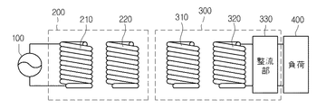
図1を参考すると、無線電力伝送システムは、給電装置100、無線電力送信装置200、無線電力受信装置300、及び負荷400を含む。
Referring to FIG. 1, the wireless power transmission system includes a
一実施形態において、給電装置100は無線電力送信装置200に含まれる。
In one embodiment, the
無線電力送信装置200は、送信誘導コイル210及び送信共振コイル220を含む。
The wireless
無線電力受信装置300は、受信共振コイル310、受信誘導コイル320、及び整流部330を含む。
The wireless
給電装置100の両端は送信誘導コイル210の両端と連結される。
Both ends of the
送信共振コイル220は、送信誘導コイル210と一定の距離を置いて配置される。
The
受信共振コイル310は、受信誘導コイル320と一定の距離を置いて配置される。
The
受信誘導コイル320の両端は整流部330の両端と連結され、負荷400は整流部330の両端に連結される。一実施形態において、負荷400は無線電力受信装置300に含まれる。
Both ends of the
給電装置100で生成された電力は無線電力送信装置200に伝えられ、無線電力送信装置200に伝えられた電力は共振現象により無線電力送信装置200と共振をなす、即ち、共振周波数値が同一な無線電力受信装置300に伝えられる。
The power generated by the
以下、より具体的に電力伝送過程を説明する。 Hereinafter, the power transmission process will be described more specifically.
給電装置100は、所定周波数を有する交流電力を生成して無線電力送信装置200に伝達する。
The
送信誘導コイル210と送信共振コイル220とは誘導結合されている。即ち、送信誘導コイル210は給電装置100から供給された電力により交流電流が流れれば、電磁気誘導により物理的に離隔している送信共振コイル220にも交流電流が誘導される。
The
その後、送信共振コイル220に伝えられた電力は共振により無線電力送信装置200と共振回路をなす無線電力受信装置300に伝えられる。
Thereafter, the power transmitted to the
インピーダンスがマッチングされた2つのLC回路の間は共振により電力が伝送できる。このような共振による電力伝送は電磁気誘導による電力伝送より遠い距離まで、より高い効率で電力伝達を可能にする。 Power can be transmitted by resonance between the two LC circuits whose impedances are matched. Such resonance-based power transmission enables power transmission with higher efficiency up to a greater distance than electromagnetic transmission power transmission.
受信共振コイル310は、送信共振コイル220から共振により電力を受信する。受信された電力により受信共振コイル310には交流電流が流れる。受信共振コイル310に伝えられた電力は電磁気誘導により受信共振コイル310と誘導結合された受信誘導コイル320に伝えられる。受信誘導コイル320に伝えられた電力は整流部330を通じて整流されて負荷400に伝えられる。
The
無線電力送信装置200の送信共振コイル220は磁場を通じて無線電力受信装置300の受信共振コイル310に電力を伝送することができる。具体的に、送信共振コイル220と受信共振コイル310とは共振周波数で動作するように共振結合されている。
The
送信共振コイル220と受信共振コイル310との共振結合により、無線電力送信装置200と無線電力受信装置300との間の電力伝送効率は格段に向上できる。
Due to the resonant coupling between the
無線電力伝送における品質指数(Quality Factor)と結合係数(Coupling Coefficient)は重要な意味を有する。即ち、電力伝送効率は品質指数及び結合係数が大きい値を有するほど向上できる。 A quality factor and a coupling coefficient in wireless power transmission are important. That is, the power transmission efficiency can be improved as the quality index and the coupling coefficient have larger values.
品質指数(Quality Factor)は、無線電力送信装置200または無線電力受信装置300の付近に蓄積できるエネルギーの指標を意味する。
The quality factor means an index of energy that can be stored in the vicinity of the wireless
品質指数(Quality Factor)は、動作周波数(w)、コイルの形状、寸法、素材などによって変わることができる。品質指数は、数式でQ=w*L/Rのように表現できる。Lはコイルのインダクタンスであり、Rはコイル自体で発生する電力損失量に該当する抵抗を意味する。 The quality factor can vary depending on the operating frequency (w), the shape, dimensions, material, etc. of the coil. The quality index can be expressed by a mathematical formula such as Q = w * L / R. L is the inductance of the coil, and R is a resistance corresponding to the amount of power loss generated in the coil itself.
品質指数(Quality Factor)は0から無限帯の値を有することができ、品質指数が大きいほど無線電力送信装置200と無線電力受信装置300との間の電力伝送効率が向上できる。
The quality factor can have a value ranging from 0 to an infinite band, and the power transmission efficiency between the wireless
結合係数(Coupling Coefficient)は送信側コイルと受信側コイルとの間の磁気的結合の程度を意味するものであって、0から1の範囲を有する。 The coupling coefficient means the degree of magnetic coupling between the transmission side coil and the reception side coil, and has a range of 0 to 1.
結合係数(Coupling Coefficient)は、送信側コイルと受信側コイルとの相対的な位置や距離などによって変わることができる。 The coupling coefficient can vary depending on the relative position and distance between the transmission side coil and the reception side coil.
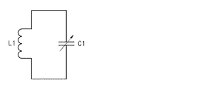
図2は、本発明の一実施形態に従う送信誘導コイル210の等価回路図である。
FIG. 2 is an equivalent circuit diagram of
図2に示すように、送信誘導コイル210はインダクタL1とキャパシタC1とからなり、これらにより適切なインダクタンスとキャパシタンス値を有する回路を構成するようになる。
As shown in FIG. 2, the
送信誘導コイル210は、インダクタL1の両端がキャパシタC1の両端に連結された等価回路で構成される。即ち、送信誘導コイル210はインダクタL1とキャパシタC1が並列に連結された等価回路で構成される。
The
キャパシタC1は可変キャパシタであることがあり、キャパシタC1のキャパシタンスが調節されることによってインピーダンスマッチングが遂行できる。送信共振コイル220、受信共振コイル310、及び受信誘導コイル320の等価回路も図2に図示されたものと同一でありうる。
The capacitor C1 may be a variable capacitor, and impedance matching can be performed by adjusting the capacitance of the capacitor C1. The equivalent circuits of the
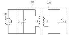
図3は、本発明の一実施形態に従う給電装置100と無線電力送信装置200の等価回路図である。
FIG. 3 is an equivalent circuit diagram of
図3に示すように、送信誘導コイル210と送信共振コイル220は、各々所定のインダクタンス値とキャパシタンス値を有するインダクタL1、L2とキャパシタC1、C2とからなる。
As shown in FIG. 3, the
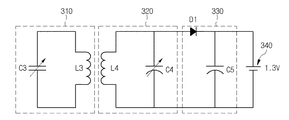
図4は、本発明の一実施形態に従う無線電力受信装置300の等価回路図である。
FIG. 4 is an equivalent circuit diagram of wireless
図4に示すように、受信共振コイル310と受信誘導コイル320は、各々所定のインダクタンス値とキャパシタンス値を有するインダクタL3、L4とキャパシタC3、C4とからなる。
As shown in FIG. 4, the
整流部330は、受信誘導コイル320から伝達された交流電力を直流電力に変換して、変換された直流電力を負荷400に伝達することができる。
The rectifying
具体的に、整流部330は整流器と平滑回路とを含む。一実施形態において、整流器はシリコン整流器が使われることができ、図4に示すように、ダイオードD1により等価化できる。
Specifically, the
整流器は、受信誘導コイル320から伝達された交流電力を直流電力に変換することができる。
The rectifier can convert AC power transmitted from the
平滑回路は、整流器で変換された直流電力に含まれた交流成分を除去して滑らかな直流電力を出力することができる。一実施形態において、平滑回路は図4に示すように、整流キャパシタC5が使われることができるが、これに限定されるものではない。 The smoothing circuit can remove the AC component contained in the DC power converted by the rectifier and output smooth DC power. In one embodiment, the smoothing circuit may include a rectifying capacitor C5 as shown in FIG. 4, but is not limited thereto.
負荷400は、直流電力を必要とする任意の充電池または装置でありうる。例えば、負荷400はバッテリーを意味する。
The
無線電力受信装置300は、携帯電話、ノートブック、マウスなど、電力を必要とする電子機器に装着できる。
The wireless
無線電力送信装置200は、無線電力受信装置300とインバンド(In band)またはアウトオブバンド(out of band)通信を用いて情報を交換することができる。
The wireless
インバンド(In band)通信は、無線電力伝送に使われる信号を用いて無線電力送信装置200と無線電力受信装置300との間の情報を交換する通信を意味する。無線電力受信装置300はスイッチをさらに含むことができ、上記スイッチのスイッチング動作を通じて無線電力送信装置200から送信される電力を受信したり、受信しないことがある。これによって、無線電力送信装置200は無線電力送信装置200で消耗される電力量を検出して無線電力受信装置300に含まれたスイッチのオンまたはオフシーン号を認識することができる。
In-band communication means communication for exchanging information between the wireless
具体的に、無線電力受信装置300は抵抗とスイッチを用いて抵抗で吸収する電力量を変化させて無線電力送信装置200で消耗される電力を変更させることができる。無線電力送信装置200は、上記消耗される電力の変化を感知して無線電力受信装置300の状態情報を獲得することができる。スイッチと抵抗とは直列に連結できる。一実施形態において、無線電力受信装置300の状態情報は、無線電力受信装置300の現在充電量、充電量の推移に対する情報を含む。
Specifically, the wireless
より具体的に説明すると、スイッチが開放されれば、抵抗が吸収する電力は0となり、無線電力送信装置200で消耗される電力も減少する。
More specifically, when the switch is opened, the power absorbed by the resistor becomes 0, and the power consumed by the wireless
スイッチが短絡されれば、抵抗が吸収する電力は0より大きくなり、無線電力送信装置200で消耗される電力は増加する。無線電力受信装置で、このような動作を繰り返すと、無線電力送信装置200は無線電力送信装置200で消耗される電力を検出して無線電力受信装置300とディジタル通信を遂行することができる。
If the switch is short-circuited, the power absorbed by the resistor becomes greater than 0, and the power consumed by the wireless
無線電力送信装置200は上記のような動作によって無線電力受信装置300の状態情報を受信し、それに適した電力を送信することができる。
The wireless
これとは反対に、無線電力送信装置200側に抵抗とスイッチを備えて無線電力送信装置200の状態情報を無線電力受信装置300に伝送することも可能である。
On the contrary, it is also possible to provide a resistor and a switch on the wireless
一実施形態において、無線電力送信装置200の状態情報は、無線電力送信装置200が伝送することができる最大供給電力量、無線電力送信装置200が電力を提供している無線電力受信装置300の個数、及び無線電力送信装置200の可用電力量に対する情報を含む。
In one embodiment, the state information of the wireless
次に、アウトオブバンド通信について説明する。 Next, out-of-band communication will be described.
アウトオブバンド通信は、共振周波数帯域でない別途の周波数帯域を用いて電力伝送に必要な情報を交換する通信をいう。無線電力送信装置200と無線電力受信装置300とはアウトオブバンド通信モジュールを装着して電力伝送に必要とする情報を交換することができる。上記アウトオブバンド通信モジュールは給電装置に装着されることもできる。一実施形態において、アウトオブバンド通信モジュールは、ブルートゥース、ジグビー、無線LAN、NFC(Near Field Communication)のような近距離通信方式を使用することができるが、これに限定されるものではない。
Out-of-band communication refers to communication in which information necessary for power transmission is exchanged using a separate frequency band that is not a resonant frequency band. The wireless
次に、図5乃至図8を参照して、本発明の更に他の実施形態に従う無線電力送信装置、無線電力受信装置、無線電力伝送方法、無線電力受信方法、情報伝送方法、及び情報受信方法を図1乃至図4の内容に結び付けて説明する。 Next, referring to FIG. 5 to FIG. 8, a wireless power transmission device, a wireless power reception device, a wireless power transmission method, a wireless power reception method, an information transmission method, and an information reception method according to still another embodiment of the present invention. Will be described in connection with the contents of FIGS.
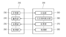
図5は、本発明の更に他の実施形態に従う無線電力送信装置及び無線電力受信装置のブロック図である。 FIG. 5 is a block diagram of a wireless power transmission device and a wireless power reception device according to still another embodiment of the present invention.
無線電力送信装置200は、送信部230、識別部240、折衷部250、及び制御部260を含む。また、図1に図示した送信誘導コイル210及び送信共振コイル220をさらに含む。
The wireless
無線電力受信装置300は、受信部350、応答信号伝送部360、折衷部370、及び制御部380を含む。また、図1に図示した受信共振コイル310、受信誘導コイル320、整流回路330、及び負荷400をさらに含む。
The wireless
送信部230は受信部350に連結信号を伝送する。一実施形態において、連結信号は無線電力受信装置300を検出し、識別するための電力信号を意味する。送信部230は無線電力受信装置300を検出するために周期的に連結信号を伝送することができる。
The
識別部240は連結信号に対する応答信号を受信して無線電力受信装置300を識別する。識別部240が連結信号に対する応答信号を受信できない場合、該当無線電力受信装置300に連結信号の送信を中断する。一実施形態において、識別部240が応答信号を受信できない場合とは、電力伝送が可能な物体でない他の物体、例えば、キー、小銭などの物体に連結信号を伝送して応答信号を受信できない場合でありうる。
The
折衷部250は、上記連結信号に対する応答信号を受信する場合、電力伝送条件を識別された無線電力受信装置300と折衷することができる。一実施形態において、電力伝送条件とは、無線電力送信装置200と無線電力受信装置300との間の電力伝送または電力中断のために相互間に備えるべき要素を意味する。上記電力伝送条件が相互間に合うか否かによって電力伝送がなされることも、なされないこともある。
When receiving the response signal to the connection signal, the
制御部260は、折衷された電力伝送条件によって識別された無線電力受信装置に電力を伝送するようにする。
The
折衷部250は、識別された無線電力受信装置300に無線電力送信装置200の状態情報を伝送して識別された無線電力受信装置300が上記無線電力送信装置200の状態情報に基づいて特定の状態情報を決めるようにし、識別された無線電力受信装置300から決まった特定の状態情報を受信する。
The
一実施形態に、無線電力送信装置200の状態情報は無線電力送信装置200が供給することができる最大電力量に対する情報、無線電力送信装置200が提供している無線電力受信装置300の個数に対する情報、及び無線電力送信装置200に対する識別情報を含む。
In an embodiment, the state information of the wireless
一実施形態に、無線電力受信装置300の状態情報は、無線電力受信装置300の現在充電量または充電量の推移に対する情報を含む。
In one embodiment, the state information of the wireless
折衷部250は、識別された無線電力受信装置300の状態情報を受信して識別された無線電力受信装置300の状態情報に基づいて特定の状態情報を決定し、制御部260は特定の状態情報に対応する電力を識別された無線電力受信装置300に伝送するようにする。
The
一実施形態に、折衷部250は識別された無線電力受信装置300に可用電力量を伝送して識別された無線電力受信装置300が可用電力量の範囲内で要求電力量を決めるようにする。その後、無線電力受信装置300が要求電力量を決定すれば、折衷部250は要求電力量を受信する。制御部260は要求電力量に該当する電力を無線電力受信装置300に伝送する。
In one embodiment, the
上記のような過程を通じて無線電力送信装置200及び無線電力受信装置300の電力伝送状態を把握して能動的な電力伝送が遂行できる。
Through the above process, the power transmission state of the wireless
無線電力受信装置300は、受信部350、応答信号伝送部360、折衷部370、及び制御部380を含む。また、図1に図示した受信共振コイル310、受信誘導コイル320、整流回路330、及び負荷400をさらに含む。
The wireless
受信部350は、無線電力送信装置200から連結信号を受信することができる。
The receiving
応答信号伝送部360は受信された連結信号に対する応答信号を上記無線電力送信装置に伝送することができる。
The response
折衷部370は無線電力送信装置200と電力伝送条件を折衷することができ、無線電力受信装置300は折衷された結果によって無線電力送信装置200から電力を受信することができる。
The
一実施形態に、折衷部370は無線電力送信装置200の状態情報を受信して無線電力送信装置200の状態情報に基づいて特定の状態情報を決定し、上記無線電力送信装置200に上記決まった特定の状態情報を無線電力送信装置200に送信することができ、無線電力受信装置300は特定の状態情報に対応する電力を上記無線電力送信装置200から受信することができる。
In one embodiment, the
上記のような過程を通じて無線電力送信装置200及び無線電力受信装置300の電力伝送状態を把握して能動的な電力伝送が遂行できる。
Through the above process, the power transmission state of the wireless
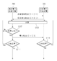
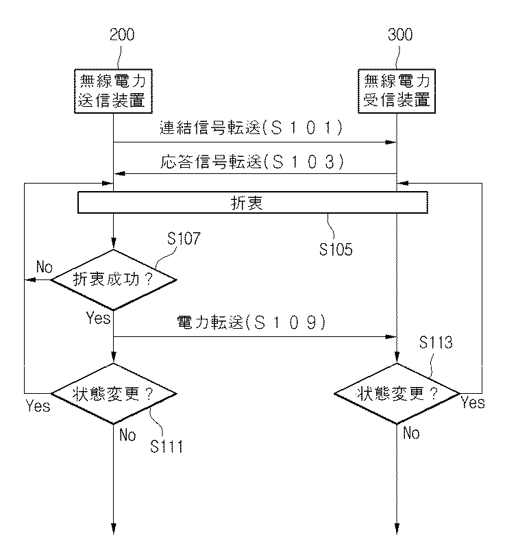
図6は、本発明の一実施形態に従う無線電力伝送方法の流れ図である。 FIG. 6 is a flowchart of a wireless power transmission method according to an embodiment of the present invention.
本発明の無線電力伝送方法は共振を用いた無線電力伝送を例として説明するが、電磁気誘導による無線電力伝送にも適用可能である。 The wireless power transmission method of the present invention will be described by taking wireless power transmission using resonance as an example, but can also be applied to wireless power transmission by electromagnetic induction.
一実施形態に、本発明の両方向通信は無線電力送信装置200及び無線電力受信装置300に電流量を変化させるための構成、例えば、可変抵抗とスイッチによるインバンド通信またはアウトオブバンド通信を通じて具現可能である。インバンド通信及びアウトオブバンド通信に対する説明は図1で説明したものと同一である。
In one embodiment, the two-way communication of the present invention can be implemented through a configuration for changing the amount of current in the wireless
図6を参照すると、無線電力送信装置200は無線電力受信装置300に連結信号を伝送する(S101)。一実施形態において、連結信号は無線電力受信装置300を検出し、識別するための電力信号を意味する。無線電力送信装置200は無線電力受信装置300を検出するために周期的に連結信号を伝送することができる。
Referring to FIG. 6, the wireless
無線電力受信装置300は連結信号を受信し、無線電力送信装置200に応答信号を伝送する(S103)。その後、無線電力送信装置200は上記連結信号に対する応答信号を受信して無線電力受信装置300を識別する。
The
仮に、無線電力送信装置200が連結信号に対する応答信号を受信できない場合、該当無線電力受信装置300に連結信号の送信を中断する。一実施形態において、無線電力送信装置200が応答信号を受信できない場合とは、電力伝送が可能な物体でない他の物体、例えば、キー、小銭などの物体に連結信号を伝送して応答信号を受信できない場合でありうる。
If the wireless
無線電力送信装置200が無線電力受信装置300を識別した場合、識別された無線電力受信装置300に電力伝送条件を折衷する(S105)。
When the wireless
仮に、無線電力送信装置200と無線電力受信装置300との間の折衷が成功すれば(S107)、無線電力送信装置200は折衷された電力伝送条件によって識別された無線電力受信装置300に電力を伝送する(S109)。
If the compromise between the wireless
識別された無線電力受信装置300に電力を伝送するか否かを決める折衷ステップ(S105)は、上記識別された無線電力受信装置300に上記無線電力送信装置200の状態情報を伝送して上記識別された無線電力受信装置300が上記無線電力送信装置200の状態情報に基づいて特定の状態情報を決めるようにするステップと、上記識別された無線電力受信装置300から上記特定の状態情報を受信するステップとを含む。
The compromise step (S105) for determining whether or not to transmit power to the identified wireless
一実施形態において、ステップS105乃至ステップS109は、次の過程を含む。無線電力送信装置200は、識別された無線電力受信装置300に可用電力量を伝送して上記識別された無線電力受信装置300が上記可用電力量の範囲内で要求電力量を決めるようにする。その後、識別された無線電力受信装置300が要求電力量を決定すれば、無線電力送信装置200は上記要求電力量を受信する。その後、無線電力送信装置200は要求電力量に該当する電力を識別された無線電力受信装置300に伝送する。
In one embodiment, steps S105 to S109 include the following process. The wireless
一実施形態において、ステップS105乃至ステップS109は、次の過程を含む。ここで、無線電力送信装置200は複数の無線電力受信装置300に無線で電力を伝送していることを例に挙げて説明する。
In one embodiment, steps S105 to S109 include the following process. Here, the case where the wireless
無線電力送信装置200は、識別された無線電力受信装置300に複数の無線電力受信装置300に電力を提供する優先順位に対する情報を伝送し、識別された無線電力受信装置300が優先順位に対する情報内で決まった優先順位を受け入れるか否かを決めるようにする。その後、識別された無線電力受信装置300が定まった優先順位を受け入れれば、無線電力送信装置200は定まった優先順位によって電力を伝送する。
The wireless
一実施形態において、ステップS105乃至ステップS109は、次の過程を含む。ここでは、複数の無線電力送信装置200が存在する場合を例に挙げて説明する。各無線電力送信装置200は、識別された無線電力受信装置300に各無線電力送信装置200の識別情報を伝送し、識別された無線電力受信装置300が複数の無線電力送信装置200のうちのいずれか1つを決めるようにする。その後、識別された無線電力受信装置300が特定の無線電力送信装置200を選択すれば、選択された無線電力送信装置200は無線電力受信装置300から選択要請信号を受信して識別された無線電力受信装置300に電力を伝送する。
In one embodiment, steps S105 to S109 include the following process. Here, a case where there are a plurality of wireless
一実施形態において、折衷ステップは無線電力送信装置200が無線電力受信装置300の状態情報を要請し、上記要請に対応する上記無線電力受信装置300の状態情報を無線電力送信装置200に伝送することを意味する。反対に、折衷ステップは無線電力受信装置300が無線電力送信装置200の状態情報を要請し、上記要請に対応する上記無線電力送信装置200の状態情報を無線電力受信装置300に伝送することを意味する。
In one embodiment, in the compromise step, the wireless
一実施形態において、折衷ステップは、無線電力送信装置200と無線電力受信装置300との間に互いに持っている状態情報を用いて電力を伝送するか否かを決めることを意味する。
In one embodiment, the compromise step means determining whether or not to transmit power using state information held between the wireless
一実施形態において、無線電力送信装置200の状態情報は、1つの無線電力送信装置200が電力を提供している無線電力受信装置300の個数に対する情報を意味する。
In one embodiment, the state information of the wireless
一実施形態において、無線電力送信装置200の状態情報は、無線電力受信装置300毎に各固有識別番号が与えられた場合、特定の無線電力送信装置200が電力を提供する無線電力受信装置300の固有識別番号に対する情報を意味する。
In one embodiment, the state information of the wireless
一実施形態において、無線電力送信装置200の状態情報は、無線電力受信装置300に提供している電力量に対する情報を意味する。
In one embodiment, the state information of the wireless
一実施形態において、無線電力送信装置200の状態情報は、複数の無線電力受信装置300に電力を提供するに当たって、各無線電力受信装置300に電力を提供する優先順位に対する情報を意味する。
In one embodiment, the state information of the wireless
一実施形態において、無線電力送信装置200の状態情報は、複数の無線電力受信装置300に電力を提供するに当たって、各無線電力受信装置300に提供している差等的な電力提供割合に対する情報を意味する。例えば、特定の無線電力送信装置200が3個の無線電力受信装置300に電力を提供している場合、50%、30%、20%の差等的な割合で3個の無線電力受信装置300に電力を提供している場合を意味する。
In one embodiment, the state information of the wireless
一実施形態において、無線電力受信装置300の状態情報は、無線電力受信装置300の現在充電量または充電量の推移に対する情報でありうる。
In one embodiment, the state information of the wireless
一実施形態において、無線電力受信装置300の状態情報は、無線電力受信装置300がどの無線電力送信装置200から電力を受信していているかに対する情報を意味する。即ち、電力の提供を受ける無線電力送信装置に対する識別情報を意味する。
In one embodiment, the state information of the wireless
仮に、無線電力送信装置200と無線電力受信装置300との間の折衷が成功すれば(S107)、無線電力送信装置200は折衷された電力伝送条件によって識別された無線電力受信装置300に電力を伝送する(S109)。
If the compromise between the wireless
仮に、電力伝送過程で、無線電力送信装置200の状態が変更されれば(S111)、折衷ステップ(S105)で戻ったり、電力伝送を中断する。
If the state of the wireless
一実施形態において、無線電力送信装置200の状態が変更される場合は、無線電力送信装置200が供給することができる電力量の変更に対する情報を意味する。この場合、外部の要因により無線電力送信装置200が提供することができる電力量が減少すれば、無線電力送信装置200は電力の提供を中断し、折衷ステップ(S105)に入って無線電力送信装置200と無線電力受信装置300との間の電力伝送量を調整する折衷を遂行する。その後、調整された電力伝送量によって折衷が成功されれば電力伝送がなされて、そうでない場合にはまた折衷ステップS105に入る。仮に、無線電力送信装置200に給電が切れたり、無線電力受信装置300の充電が完了した場合には電力伝送を終了する。
In one embodiment, when the state of the wireless
一実施形態において、無線電力送信装置200の状態が変更される場合は、無線電力送信装置200が電力を提供している無線電力受信装置300の個数が変更されることに対する情報を意味する。
In one embodiment, when the state of the wireless
仮に、電力伝送過程で、無線電力受信装置300の状態が変更されれば(S113)、折衷ステップ(S105)に戻ったり、電力伝送を中断する。
If the state of the wireless
一実施形態において、無線電力受信装置300の状態が変更される場合は、現在無線電力送信装置200が伝送している無線電力受信装置300の以外の新たな無線電力受信装置300が検出される場合を意味する。
In one embodiment, when the state of the wireless
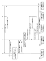
図7は、本発明の更に他の実施形態に従う無線電力伝送方法を説明するためのラダーダイヤグラムである。 FIG. 7 is a ladder diagram illustrating a wireless power transmission method according to still another embodiment of the present invention.
図7を参照すると、まず無線電力送信装置200は、各無線電力送信装置201、202、203に状態情報を要請する(S201)。図7には3個の無線電力送信装置201、202、203のみ図示されているが、これに限定されるものではない。各無線電力送信装置201、202、203は、図5で説明した無線電力送信装置200の構成を全て含む。ここで、状態情報は、無線電力送信装置が伝送することができる最大供給電力量、無線電力送信装置が電力を提供している無線電力受信装置300の個数、及び無線電力送信装置の可用電力量を含むが、これに限定されるものではない。
Referring to FIG. 7, first, the wireless
一実施形態において、無線電力送信装置200と他の無線電力送信装置201、202、203は、インバンドまたはアウトオブバンド通信を通じて情報を送受信することができる。
In one embodiment, the wireless
無線電力送信装置200は、状態情報要請に対応して無線電力送信装置201、202、203からそれぞれの状態情報を受信する(S203)。
The wireless
無線電力送信装置200は、受信した各無線電力送信装置201、202、203の状態情報に基づいて状態リストを生成する(S205)。一実施形態において、状態リストは各無線電力送信装置201、202、203の状態情報を収集して生成されたリストでありうる。上記状態リストは、<表1>を通じてより詳細に説明する。
The wireless
<表1>は無線電力送信装置200が3個の無線電力送信装置(A、B、C)から受信した状態情報に基づいて生成した状態リストの例を表す。また、図示してはいないが、無線電力送信装置200は自身の状態情報を含んで状態リストを生成することもできる。
Table 1 shows an example of a state list generated by the wireless
<表1>で、無線電力送信装置(A)の最大供給電力量は100Wであり、4個の無線電力受信装置300に電力を供給している。また、無線電力送信装置(A)は20Wの可用電力量が残っていることを意味する。ここで、可用電力量は無線電力送信装置200が現在提供している多数の無線電力受信装置300の以外の他の無線電力受信装置300に提供することができる電力量を意味する。また、無線電力送信装置(A)が提供している4個の無線電力受信装置300の各要求電力量は一定の電力量に限定されるものではなく、各々異なることがある。
In <Table 1>, the maximum power supply amount of the wireless power transmission device (A) is 100 W, and power is supplied to the four wireless
各無線電力送信装置200の可用電力量は、各無線電力送信装置201、202、203毎に異なることがある。
The available power amount of each wireless
無線電力送信装置(B)の最大供給電力量は200Wであり、5個の無線電力受信装置300に電力を供給している。また、無線電力送信装置(B)の可用電力量は15Wである。また、無線電力送信装置(B)が提供している5個の無線電力受信装置300の各要求電力量は一定の電力量に限定されるものではなく、異なることがある。
The maximum power supply amount of the wireless power transmission device (B) is 200 W, and power is supplied to the five wireless
無線電力送信装置(C)の最大供給電力量は300Wであり、6個の無線電力受信装置300に電力を供給している。また、無線電力送信装置(C)の可用電力量は30Wである。無線電力送信装置(C)が提供している6個の無線電力受信装置300の各要求電力量は一定の電力量に限定されるものではなく、異なることがある。
The maximum power supply amount of the wireless power transmission device (C) is 300 W, and power is supplied to the six wireless
その後、無線電力送信装置200は無線電力受信装置300から上記状態リストの伝送要請を受信する(S207)。一実施形態において、無線電力送信装置200と無線電力受信装置300とはインバンド通信またはアウトオブバンド通信を用いて情報を送受信することができる。
Thereafter, the wireless
無線電力送信装置200は、上記状態リストの伝送要請に応答して無線電力受信装置300に状態リストを伝送する(S209)。
The wireless
その後、無線電力受信装置300は上記受信した状態リストに基づいて電力受信のために複数の無線電力送信装置201、202、203のうち、1つ以上の無線電力送信装置を選択する(S211)。即ち、無線電力受信装置300は各無線電力送信装置の状態情報である最大供給電力量、各無線電力送信装置が電力を提供している無線電力受信装置の個数、及び各無線電力送信装置の可用電力量を考慮して1つ以上の無線電力送信装置を選択することができる。
Thereafter, the wireless
一実施形態において、無線電力受信装置300は3個の無線電力送信装置201、202、203のうち、可用電力量の最も多い無線電力送信装置203を選択することができる。即ち、これは、無線電力受信装置300が25wの電力量を必要として25wの電力量を提供してくれることができる場合でありうる。しかしながら、これに限定されるものではなく、無線電力受信装置300は2つの無線電力送信装置201、203を選択することもできる。
In one embodiment, the wireless
一実施形態において、無線電力受信装置300は3個の無線電力送信装置201、202、203のうち、電力を提供している無線電力受信装置の個数が最も少ない無線電力送信装置(A)を選択することもできる。
In one embodiment, the wireless
即ち、このように、無線電力受信装置300は状態リストに基づいて電力伝送に適合した無線電力送信装置を選択することができる。
That is, in this way, the wireless
その後、無線電力受信装置300は1つ以上の無線電力送信装置の選択に対する選択情報を無線電力送信装置200に伝送する(S213)。ここで、選択情報は、無線電力受信装置300が複数の無線電力送信装置201、202、203のうち、どれを選択したかに対する情報を含む。具体的に、複数の無線電力送信装置201、202、203の各々が識別記号(A、B、C)を含む場合、選択情報は上記識別記号に対する情報を含む。
Thereafter, the wireless
無線電力送信装置200は、上記受信した選択情報に基づいて選択された無線電力送信装置201に電力伝送要請を伝送する(S215)。図7では無線電力送信装置201に電力伝送要請を伝送することとなっているが、これに限定されるものではない。
The wireless
選択された無線電力送信装置201は、無線電力受信装置300に電力を伝送する(S217)。一実施形態において、選択された無線電力送信装置201は電磁気誘導または共振を用いて無線電力受信装置300に無線で電力を伝送することができる。
The selected wireless
このように、本発明の実施形態に従って無線電力送信装置200と無線電力受信装置300とは両方向通信を通じて相互間の情報を共有して電力状況に合う能動的な電力伝送を遂行することができる。これによって、相互間の電力伝送が効率的になされることができる。
As described above, according to the embodiment of the present invention, the wireless
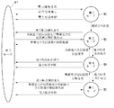
図8は、本発明の一実施形態に従う無線電力伝送のための状態遷移図である。 FIG. 8 is a state transition diagram for wireless power transmission according to an embodiment of the present invention.
以下、図1乃至図7の内容に結び付けて本発明の一実施形態に従う無線電力伝送のための状態遷移図を説明する。 Hereinafter, a state transition diagram for wireless power transmission according to one embodiment of the present invention will be described in connection with the contents of FIGS.
−第1ステップ(選択モード)
まず、無線電力送信装置200と無線電力受信装置300とを含んだ無線電力伝送システムは第1モードM1にある。一実施形態において、第1モードM1は選択モードでありうる。上記第1モードで、無線電力送信装置200は一般的に物体の除去及び配置に対するインターフェース領域を管理することができる。
-First step (selection mode)
First, the wireless power transmission system including the
無線電力送信装置200は1つ以上の物体を発見すれば、上記1つ以上の物体の位置を探すための試みを遂行しなければならない。さらに、無線電力送信装置200は電力を受信することができる無線電力受信装置300とその他の外部の物体(例えば、キー、小銭などの物体)を区別するための試みを行うことができる。
If the wireless
また、無線電力送信装置200は電力伝送のための無線電力受信装置300を選択する試みを遂行しなければならない。このような目的を達成するために、無線電力送信装置200が初期に充分な情報を持っていなければ、無線電力送信装置200は後述する連結モード及びそれに連続して識別と設定モードとを繰り返して進行し、関連された情報を収集した後、選択ステップに遷移することができる。
In addition, the wireless
−第2ステップ(連結モード)
一実施形態において、第2モードM2は連結モードでありうる。一実施形態において、第2モードM2は無線電力送信装置200と無線電力受信装置300との間の通信を遂行するために基本的な準備ができた状態でありうる。
-Second step (concatenation mode)
In one embodiment, the second mode M2 may be a connected mode. In an exemplary embodiment, the second mode M2 may be a state in which basic preparations for performing communication between the wireless
第1モードM1で、無線電力伝送システムは無線電力送信装置200が無線電力受信装置300を発見した場合、無線電力受信装置300に電力を伝送するための第2モードM2に遷移する。即ち、無線電力受信装置300の存在が認識された場合、無線電力伝送システムは第2モードに遷移して、無線電力受信装置300に連結信号を伝送することができる。上記連結信号は無線電力受信装置300の状態情報を受信するために無線電力送信装置200が無線電力受信装置300に伝送する接続信号でありうる。
In the first mode M1, when the wireless
仮に、無線電力送信装置200が無線電力受信装置300から連結信号に対する応答信号を受信できない場合、連結信号の送信を中断し、第1モードM1に遷移する。仮に、無線電力送信装置200が無線電力受信装置300から負荷(または、バッテリー)400が十分に充電されているという応答信号を受信した場合、無線電力送信装置200は電力伝送を終了する。
If the wireless
第2モードM2で、無線電力送信装置200が無線電力受信装置300から電力伝送を要請する応答信号を受信した場合、無線電力送信装置200は追加的な連結信号を新たな無線電力受信装置300に送信することができる。追加的な連結信号は新たな無線電力受信装置300を検出するための信号を意味する。
In the second mode M2, when the wireless
無線電力送信装置200の追加的な連結信号に対応した応答信号がない場合、新たな無線電力受信装置300を検出する動作を止める。
When there is no response signal corresponding to the additional connection signal of the wireless
−第3モード(識別及び設定)
第2モードM2で、無線電力送信装置200が無線電力受信装置300に連結信号に対する応答信号を受信した場合、無線電力受信装置300の識別情報及び状態情報を収集する第3モードM3に遷移する。一実施形態において、第3モードM3は識別及び設定モードでありうる。ここで、無線電力受信装置300の識別情報は無線電力受信装置300の種類、機種、モデルなどの情報を意味するが、これに限定されるものではない。無線電力受信装置300の状態情報は、負荷(または、バッテリー)400に提供することができる最大電力量(または、最大充電量)、負荷(または、バッテリー)400に残っている現在電力量などを意味するが、これに限定されるものではない。無線電力送信装置200は、無線電力受信装置300と電力伝送条件を生成するために、無線電力受信装置300の識別情報及び状態情報を用いる。電力伝送条件という、無線電力送信装置200から無線電力受信装置300への電力伝送を特性化するための条件の集合を意味する。
-Third mode (identification and setting)
In the second mode M2, when the wireless
第3モードM3で、電力伝送条件に制約が発生すれば、第1モードM1に遷移する。一実施形態において、電力伝送条件に対する制約は電力伝送条件が成立しない場合を意味する。一実施形態において、電力伝送条件に対する制約は予想できなかったデータパケットが無線電力送信装置200と無線電力受信装置300との間に伝送されることを意味する。一実施形態において、電力伝送条件に対する制約は、時間超過のような状況を意味する。時間超過は電力を受信する無線電力受信装置300が除去された後、一定時間が経った後、電力伝送を中断する場合を含む。
In the third mode M3, if there is a restriction on the power transmission condition, the mode is changed to the first mode M1. In one embodiment, the restriction on the power transmission condition means that the power transmission condition is not satisfied. In one embodiment, the restriction on the power transmission condition means that an unexpected data packet is transmitted between the wireless
第3モードM3で、電力伝送条件に制約が発生することによって第1モードM1に遷移された状態で、無線電力送信装置200は無線電力受信装置300と関連した状態情報を無線電力受信装置300に伝送し、また第3モードM3に遷移することができる。一実施形態において、無線電力送信装置200の状態情報は、1つの無線電力送信装置200が電力を提供している無線電力受信装置300の個数に対する情報を意味する。
In the third mode M3, the wireless
一実施形態において、無線電力送信装置200の状態情報は、無線電力受信装置300毎に各固有識別番号が与えられた場合、特定の無線電力送信装置200が電力を提供する無線電力受信装置300の固有識別番号に対する情報を意味する。
In one embodiment, the state information of the wireless
一実施形態において、無線電力送信装置200の状態情報は、無線電力受信装置300に提供している電力量に対する情報を意味する。
In one embodiment, the state information of the wireless
一実施形態において、無線電力送信装置200の状態情報は、無線電力受信装置300に電力を提供するに当たって、各無線電力受信装置300に電力を提供する優先順位に対する情報を意味する。
In one embodiment, the state information of the wireless
一実施形態において、無線電力送信装置200の状態情報は、無線電力受信装置300に電力を提供するに当たって、各無線電力受信装置300に提供している差等的な電力提供割合に対する情報を意味する。例えば、特定の無線電力送信装置200が3個の無線電力送信装置300に電力を提供している場合、50%、30%、20%の割合で差等的に無線電力受信装置300に電力を提供しているという情報をいう。
In one embodiment, the state information of the wireless
第3モードM3で、無線電力受信装置300の個数が特定個数を超過する場合、また第1モードM1に遷移することができる。即ち、特定の無線電力送信装置200が5個の無線電力受信装置300に電力を提供する場合、新たな無線電力受信装置300が検出されれば、新しく検出された無線電力受信装置300に電力を伝送できないように第1モードM1に遷移する。
In the third mode M3, when the number of wireless
−第4モード(電力伝送)
第3モードM3で、電力伝送条件が成立した場合、無線電力伝送システムは第4モードM4に遷移することができる。一実施形態において、第4モードM4は無線電力送信装置200が無線電力受信装置に電力を伝送している状態を意味する。一実施形態において、第4モードM4は無線電力送信装置200が無線電力受信装置300から受信した情報に対応してコイルに流れる電流を調節しながら無線電力受信装置300に電力を伝送するステップでありうる。
-Fourth mode (power transmission)
When the power transmission condition is satisfied in the third mode M3, the wireless power transmission system can transition to the fourth mode M4. In an embodiment, the fourth mode M4 means a state in which the wireless
第4モードM4で、電力伝送条件のうちのいずれか1つの条件が成立しない場合、無線電力送信装置200は無線電力受信装置300への電力伝送を中断させ、第1モードM1に遷移する。一実施形態において、電力伝送条件に対する制約は電力伝送条件が成立しない場合を意味する。一実施形態において、電力伝送条件に対する制約は予想できなかったデータパケットが無線電力送信装置200と無線電力受信装置300との間に伝送されることを意味する。一実施形態において、電力伝送条件に対する制約は時間超過のような状況を意味する。時間超過は電力を受信する無線電力受信装置300が除去された後、一定時間が経った後、電力伝送を中断する場合を含む。
When any one of the power transmission conditions is not satisfied in the fourth mode M4, the wireless
第4モードM4で、無線電力送信装置200が無線電力受信装置300から無線電力受信装置300の負荷(または、バッテリー)400が十分に充電されているという応答信号を受信した場合、無線電力送信装置300は電力伝送を終了し、第1モードM1に遷移する。
In the fourth mode M4, when the wireless
第4モードM4で、無線電力受信装置300の状態が変更された場合、第3モードM3に遷移することができる。
When the state of the
一実施形態において、無線電力受信装置300の状態が変更された場合とは、無線電力送信装置200が無線電力受信装置300に電力を伝送している過程で新たな無線電力受信装置300が検出された場合を意味する。この場合、無線電力伝送システムは第4モードM4から第3モードM3に遷移する。その後、無線電力送信装置200は無線電力受信装置300の識別情報及び状態情報を収集するための作業を遂行し、無線電力伝送条件が成立した場合、また第4モードM4に遷移する。仮に、無線電力伝送条件に制約が発生した場合、第1モードM1に遷移する。
In the embodiment, when the state of the wireless
一実施形態において、無線電力受信装置300の状態が変更された場合とは、無線電力送信装置200が電力を提供することができる無線電力受信装置300の個数を超過して新たな少なくとも1つ以上の無線電力受信装置300が検出された場合を意味する。この場合、無線電力伝送システムは第4モードM4から第3モードM3に遷移する。その後、無線電力送信装置200は無線電力受信装置300の識別情報及び状態情報を収集するための作業を遂行し、無線電力送信装置200が提供することができる範囲の個数を超過した無線電力受信装置300においては第1モードM1に遷移する。
In one embodiment, when the state of the wireless
−第5モード(電力伝送及び両方向通信)
第4モードM4で、無線電力伝送システムは無線電力送信装置200と無線電力受信装置300とは相互間の情報を共有するために第5モードM5に遷移することができる。
-5th mode (power transmission and bidirectional communication)
In the fourth mode M4, in the wireless power transmission system, the wireless
一実施形態において、第5モードM5は電力伝送及び両方向通信ステップでありうる。一実施形態において、第5モードM5は無線電力送信装置200と無線電力受信装置300との間の電力伝送を遂行しながら各自の変更される状態に対する情報を共有するモードでありうる。
In an embodiment, the fifth mode M5 may be a power transmission and bidirectional communication step. In an exemplary embodiment, the fifth mode M5 may be a mode in which information regarding each changed state is shared while performing power transmission between the wireless
一実施形態において、変更される状態に対する情報は、無線電力送信装置200の個数が変更されたり、無線電力送信装置200が供給することができる電力量が変更される状態などの情報を意味する。
In one embodiment, the information regarding the state to be changed means information such as a state in which the number of wireless
一実施形態において、無線電力送信装置200の変更される状態情報は、1つの無線電力送信装置200が電力を提供している無線電力受信装置300の個数の変更に対する情報を意味する。
In one embodiment, the changed state information of the wireless
一実施形態において、無線電力送信装置200の変更される状態情報は、無線電力受信装置300毎に各固有識別番号が与えられた場合、特定の無線電力送信装置200が電力を提供する無線電力受信装置300の固有識別番号に対する情報の変更を意味する。
In one embodiment, the state information to be changed of the wireless
一実施形態において、無線電力送信装置200の変更される状態情報は、今後無線電力受信装置300に提供することができる電力量に対する情報を意味する。
In one embodiment, the changed state information of the wireless
一実施形態において、無線電力送信装置200の変更される状態情報は、無線電力受信装置300に電力を提供するに当たって、各無線電力受信装置300に電力を提供する優先順位に対する情報を意味する。
In one embodiment, the changed state information of the wireless
一実施形態において、無線電力送信装置200の変更される状態情報は、無線電力受信装置300に電力を提供するに当たって、各無線電力受信装置300に提供している差等的な電力提供割合に対する情報を意味する。例えば、特定の無線電力送信装置200が3個の無線電力送信装置300に電力を提供している場合、50%、30%、20%の割合で差等的に無線電力受信装置300に電力を提供している状況で各無線電力受信装置300の充電量によって割合を30%、50%、20%に変更することに対する情報を意味する。
In one embodiment, the changed state information of the wireless
第5モードM5で、電力伝送条件に制約が発生すれば、第1モードM1に遷移する。一実施形態において、電力伝送条件に対する制約は電力伝送条件が不成立する場合を意味する。一実施形態において、電力伝送条件に対する制約は予想できなかったパケットが無線電力送信装置200と無線電力受信装置300との間に伝送されることを意味する。一実施形態において、電力伝送条件に対する制約は時間超過のような状況を意味する。時間超過は電力を受信する無線電力受信装置300が除去された後、一定時間が経った後、電力伝送を中断する場合を含む。
In the fifth mode M5, if there is a restriction on the power transmission condition, the mode is changed to the first mode M1. In one embodiment, the restriction on the power transmission condition means that the power transmission condition is not satisfied. In one embodiment, the restriction on the power transmission condition means that a packet that cannot be predicted is transmitted between the wireless
第5モードM5で、電力伝送条件に制約が発生して第1モードM1に遷移された場合、無線電力送信装置200は無線電力受信装置300と関連した状態情報を無線電力受信装置300に伝送し、また第5モードM5に遷移することができる。
When the power transmission condition is restricted in the fifth mode M5 and the mode is changed to the first mode M1, the wireless
第5モードM5で、無線電力送信装置200が無線電力受信装置300から無線電力受信装置300の負荷(または、バッテリー)400が十分に充電されているという応答信号を受信した場合、無線電力送信装置300は電力伝送を終了し、第1モードM1に遷移する。
In the fifth mode M5, when the wireless
第5モードM5で、無線電力受信装置300の状態が変更された場合、第4モードM4に遷移することができる。
When the state of the
一実施形態において、無線電力受信装置300の状態が変更された場合とは、無線電力送信装置200が無線電力受信装置300に電力を伝送し、両方向通信を遂行している過程で新たな無線電力受信装置300が検出された場合を意味する。
In one embodiment, the state of the
この場合、無線電力伝送システムは第5モードM5から第4モードM4に遷移し、その後、無線電力送信装置200は新たな無線電力受信装置300の識別情報及び状態情報を収集するための作業を遂行し、無線電力伝送条件が成立した場合、また第5モードM5に遷移する。仮に、無線電力伝送条件に制約が発生した場合、第1モードM1に遷移する。
In this case, the wireless power transmission system transitions from the fifth mode M5 to the fourth mode M4, and then the wireless
本実施形態では共振を用いた無線電力伝送を例に挙げて説明したが、本発明の両方向通信を用いた無線電力伝送方法、無線電力受信方法、及び電力制御方法は、電磁気誘導、RF方式などを用いた他の無線電力伝送にも適用可能である。 In this embodiment, wireless power transmission using resonance has been described as an example. However, a wireless power transmission method, a wireless power reception method, and a power control method using bidirectional communication according to the present invention include electromagnetic induction, RF method, and the like. The present invention can also be applied to other wireless power transmission using the.
以上、本発明の好ましい実施形態に対して図示及び説明したが、本発明は前述した特定の実施形態に限定されるものではなく、請求範囲で請求する本発明の要旨を逸脱することなく当該発明が属する技術分野で通常の知識を有する者により多様な変形実施が可能であることは勿論であり、このような変形実施は本発明の技術的思想や展望から個別的に理解されてはならない。 Although the preferred embodiments of the present invention have been illustrated and described above, the present invention is not limited to the specific embodiments described above, and the invention is not deviated from the gist of the present invention claimed in the claims. It goes without saying that various modifications can be made by persons having ordinary knowledge in the technical field to which the invention belongs, and such modifications should not be individually understood from the technical idea and perspective of the present invention.
Claims (60)
第1可用電力を含む第1無線電力送信装置の第1状態情報を送信する段階;
前記第1可用電力範囲内で決定された第1要求電力が含まれた第1無線電力受信装置の第1状態情報を受信する段階;
前記第1無線電力受信装置の前記第1状態情報に基づいて決定された電力を前記第1無線電力受信装置に送信する第1電力送信段階;
第2可用電力を含む前記第1無線電力送信装置の第2状態情報を送信する段階;
前記第2可用電力範囲内で決定された第2要求電力が含まれた前記第1無線電力受信装置の第2状態情報を受信する段階;及び
前記第1無線電力受信装置の前記第2状態情報に基づいて決定された電力を前記第1無線電力受信装置に送信する第2電力送信段階;
を含み、
前記第1無線電力送信装置の前記第2状態情報は、前記第1無線電力送信装置の状態が変更された場合に送信する、無線電力送信方法。 A wireless power transmission method of a wireless power transmission device that wirelessly transmits power to a wireless power reception device, comprising:
Transmitting the first state information of the first wireless power transmission device including the first available power;
Receiving the first state information of the first wireless power receiver including the first required power determined within the first available power range;
A first power transmission step of transmitting, to the first wireless power receiver, power determined based on the first state information of the first wireless power receiver;
Transmitting second state information of the first wireless power transmission device including second available power;
Receiving second state information of the first wireless power receiver including the second required power determined within the second available power range; and the second state information of the first wireless power receiver A second power transmission step of transmitting to the first wireless power receiver the power determined based on
Including
The wireless power transmission method, wherein the second state information of the first wireless power transmission device is transmitted when a state of the first wireless power transmission device is changed.
第1可用電力を含む第1無線電力送信装置の第1状態情報を受信する段階;
前記第1可用電力範囲内で第1要求電力を決定する段階;
前記第1要求電力が含まれた第1無線電力受信装置の第1状態情報を送信する段階;
前記第1無線電力受信装置の前記第1状態情報に基づいて決定された電力を前記第1無線電力送信装置から受信する第1電力受信段階;
第2可用電力を含む前記第1無線電力送信装置の第2状態情報を受信する段階;
前記第2可用電力範囲内で第2要求電力を決定する段階;
前記第2要求電力が含まれた前記第1無線電力受信装置の第2状態情報を送信する段階;及び
前記第1無線電力受信装置の前記第2状態情報に基づいて決定された電力を前記第1無線電力送信装置から受信する第2電力受信段階を含み、
前記第1無線電力送信装置の前記第2状態情報は、前記第1無線電力送信装置の状態が変更された場合に受信される、無線電力受信方法。 A wireless power receiving method of a wireless power receiving device that wirelessly receives power from a wireless power transmitting device,
Receiving first state information of the first wireless power transmission device including the first available power;
Determining a first required power within the first available power range;
Transmitting the first state information of the first wireless power receiver including the first required power;
A first power receiving step of receiving, from the first wireless power transmitter, power determined based on the first state information of the first wireless power receiver;
Receiving second state information of the first wireless power transmission device including second available power;
Determining a second required power within the second available power range;
Transmitting the second state information of the first wireless power receiver including the second required power; and determining the power determined based on the second state information of the first wireless power receiver. A second power receiving stage for receiving from one wireless power transmitting device;
The wireless power reception method, wherein the second state information of the first wireless power transmission device is received when a state of the first wireless power transmission device is changed.
第1可用電力を含む第1無線電力送信装置の第1状態情報を送信し、第1可用電力範囲内で決定された第1要求電力が含まれた第1無線電力受信装置の第1状態情報を受信する協商部;及び
前記第1無線電力受信装置の前記第1状態情報に基づいて決定された電力を前記第1無線電力受信装置に送信するようにする制御部;
を含み、
前記協商部は、
第2可用電力を含む前記第1無線電力送信装置の第2状態情報を送信し、第2可用電力範囲内で決定された第2要求電力が含まれた前記第1無線電力受信装置の第2状態情報を受信し、
前記制御部は、
前記第1無線電力受信装置の前記第2状態情報に基づいて決定された電力を前記第1無線電力受信装置に送信するようにし、
前記協商部は、
前記第1無線電力送信装置の前記第2状態情報を前記第1無線電力送信装置の状態が変更された場合に送信する、無線電力送信装置。 A wireless power transmitter that wirelessly transmits power to a wireless power receiver,
The first state information of the first wireless power receiving apparatus that transmits the first state information of the first wireless power transmitting apparatus including the first available power and includes the first required power determined within the first available power range. A control unit that transmits power determined based on the first state information of the first wireless power receiver to the first wireless power receiver;
Including
The Commerce Department is
The second state information of the first wireless power transmitter including the second available power is transmitted, and the second state information of the first wireless power receiver including the second required power determined within the second available power range is transmitted. Receive status information,
The controller is
Transmitting power determined based on the second state information of the first wireless power receiver to the first wireless power receiver;
The Commerce Department is
A wireless power transmission device that transmits the second state information of the first wireless power transmission device when a state of the first wireless power transmission device is changed.
前記第1無線電力送信装置の前記第2状態情報を送信する前に、前記第1無線電力送信装置の前記第2状態情報を要請する所定の要請信号を受信する、請求項31〜33のいずれか一項に記載の無線電力送信装置。 The Commerce Department is
34. Any one of claims 31 to 33, wherein a predetermined request signal for requesting the second state information of the first wireless power transmission device is received before transmitting the second state information of the first wireless power transmission device. The wireless power transmission device according to claim 1.
をさらに含む、請求項31〜34のいずれか一項に記載の無線電力送信装置。 An identification unit for identifying the second wireless power receiver by the first wireless power transmitter before transmitting the second state information of the first wireless power receiver;
The wireless power transmission device according to any one of claims 31 to 34, further including:
第1可用電力を含む第1無線電力送信装置の第1状態情報を受信し、前記第1可用電力範囲内で第1要求電力を決定し、前記第1要求電力が含まれた第1無線電力受信装置の第1状態情報を送信する協商部;及び
前記第1無線電力受信装置の前記第1状態情報に基づいて決定された電力を前記第1無線電力送信装置から受信するようにする制御部;
を含み、
前記協商部は、
第2可用電力を含む前記第1無線電力送信装置の第2状態情報を受信し、前記第2可用電力範囲内で第2要求電力を決定し、前記第2要求電力が含まれた前記第1無線電力受信装置の第2状態情報を送信し、
前記制御部は、
前記第1無線電力受信装置の前記第2状態情報に基づいて決定された電力を前記第1無線電力送信装置から受信するようにし、
前記協商部は、
前記第1無線電力送信装置の前記第2状態情報を前記第1無線電力送信装置の状態が変更された場合に受信する、無線電力受信装置。 A wireless power receiver that wirelessly receives power from a wireless power transmitter,
The first wireless power including the first required power is received, the first state information of the first wireless power transmission device including the first available power is received, the first required power is determined within the first available power range, and the first required power is included. A trader that transmits first state information of the receiving device; and a control unit that receives power determined based on the first state information of the first wireless power receiving device from the first wireless power transmitting device. ;
Including
The Commerce Department is
The second state information of the first wireless power transmission device including the second available power is received, a second required power is determined within the second available power range, and the first required power is included in the first Transmitting the second state information of the wireless power receiver,
The controller is
Receiving power determined based on the second state information of the first wireless power receiver from the first wireless power transmitter;
The Commerce Department is
A wireless power receiver that receives the second state information of the first wireless power transmitter when the state of the first wireless power transmitter is changed.
Applications Claiming Priority (2)
| Application Number | Priority Date | Filing Date | Title |
|---|---|---|---|
| KR1020110117233A KR101338732B1 (en) | 2011-11-10 | 2011-11-10 | Wireless power transmitter, wireless power receiver, wireless power transmission method, wireless power reception method, information transmission method and information reception method |
| KR10-2011-0117233 | 2011-11-10 |
Related Parent Applications (1)
| Application Number | Title | Priority Date | Filing Date |
|---|---|---|---|
| JP2012245483A Division JP6185230B2 (en) | 2011-11-10 | 2012-11-07 | Wireless power transmission device, wireless power reception device, wireless power transmission method, and wireless power reception method |
Related Child Applications (1)
| Application Number | Title | Priority Date | Filing Date |
|---|---|---|---|
| JP2019040411A Division JP6748249B2 (en) | 2011-11-10 | 2019-03-06 | Wireless power transmission method, wireless power reception method, wireless power transmission device, wireless power reception device |
Publications (2)
| Publication Number | Publication Date |
|---|---|
| JP2017209010A true JP2017209010A (en) | 2017-11-24 |
| JP6497717B2 JP6497717B2 (en) | 2019-04-10 |
Family
ID=47225979
Family Applications (4)
| Application Number | Title | Priority Date | Filing Date |
|---|---|---|---|
| JP2012245483A Active JP6185230B2 (en) | 2011-11-10 | 2012-11-07 | Wireless power transmission device, wireless power reception device, wireless power transmission method, and wireless power reception method |
| JP2017144604A Active JP6497717B2 (en) | 2011-11-10 | 2017-07-26 | Wireless power transmission method, wireless power reception method, wireless power transmission device, and wireless power reception device |
| JP2019040411A Active JP6748249B2 (en) | 2011-11-10 | 2019-03-06 | Wireless power transmission method, wireless power reception method, wireless power transmission device, wireless power reception device |
| JP2020133729A Active JP6975293B2 (en) | 2011-11-10 | 2020-08-06 | Wireless power transmission method, wireless power reception method, wireless power transmission device, wireless power receiver |
Family Applications Before (1)
| Application Number | Title | Priority Date | Filing Date |
|---|---|---|---|
| JP2012245483A Active JP6185230B2 (en) | 2011-11-10 | 2012-11-07 | Wireless power transmission device, wireless power reception device, wireless power transmission method, and wireless power reception method |
Family Applications After (2)
| Application Number | Title | Priority Date | Filing Date |
|---|---|---|---|
| JP2019040411A Active JP6748249B2 (en) | 2011-11-10 | 2019-03-06 | Wireless power transmission method, wireless power reception method, wireless power transmission device, wireless power reception device |
| JP2020133729A Active JP6975293B2 (en) | 2011-11-10 | 2020-08-06 | Wireless power transmission method, wireless power reception method, wireless power transmission device, wireless power receiver |
Country Status (8)
| Country | Link |
|---|---|
| US (8) | US9197070B2 (en) |
| EP (10) | EP3393051B1 (en) |
| JP (4) | JP6185230B2 (en) |
| KR (1) | KR101338732B1 (en) |
| CN (2) | CN104600869B (en) |
| DE (1) | DE202012013165U1 (en) |
| PL (1) | PL3731427T3 (en) |
| TW (1) | TWI491137B (en) |
Cited By (2)
| Publication number | Priority date | Publication date | Assignee | Title |
|---|---|---|---|---|
| KR20190000363A (en) * | 2016-06-08 | 2019-01-02 | 엘지전자 주식회사 | Wireless power transmission method and apparatus therefor |
| US11689065B2 (en) | 2019-02-15 | 2023-06-27 | Honda Motor Co., Ltd. | System and methods for charging a device |
Families Citing this family (131)
| Publication number | Priority date | Publication date | Assignee | Title |
|---|---|---|---|---|
| KR101338732B1 (en) * | 2011-11-10 | 2013-12-06 | 엘지이노텍 주식회사 | Wireless power transmitter, wireless power receiver, wireless power transmission method, wireless power reception method, information transmission method and information reception method |
| US10381880B2 (en) | 2014-07-21 | 2019-08-13 | Energous Corporation | Integrated antenna structure arrays for wireless power transmission |
| US9787103B1 (en) | 2013-08-06 | 2017-10-10 | Energous Corporation | Systems and methods for wirelessly delivering power to electronic devices that are unable to communicate with a transmitter |
| US12057715B2 (en) | 2012-07-06 | 2024-08-06 | Energous Corporation | Systems and methods of wirelessly delivering power to a wireless-power receiver device in response to a change of orientation of the wireless-power receiver device |
| US10256657B2 (en) | 2015-12-24 | 2019-04-09 | Energous Corporation | Antenna having coaxial structure for near field wireless power charging |
| US10063105B2 (en) | 2013-07-11 | 2018-08-28 | Energous Corporation | Proximity transmitters for wireless power charging systems |
| US11502551B2 (en) | 2012-07-06 | 2022-11-15 | Energous Corporation | Wirelessly charging multiple wireless-power receivers using different subsets of an antenna array to focus energy at different locations |
| US9876394B1 (en) | 2014-05-07 | 2018-01-23 | Energous Corporation | Boost-charger-boost system for enhanced power delivery |
| US9867062B1 (en) | 2014-07-21 | 2018-01-09 | Energous Corporation | System and methods for using a remote server to authorize a receiving device that has requested wireless power and to determine whether another receiving device should request wireless power in a wireless power transmission system |
| US10992187B2 (en) | 2012-07-06 | 2021-04-27 | Energous Corporation | System and methods of using electromagnetic waves to wirelessly deliver power to electronic devices |
| US9853458B1 (en) * | 2014-05-07 | 2017-12-26 | Energous Corporation | Systems and methods for device and power receiver pairing |
| US10965164B2 (en) | 2012-07-06 | 2021-03-30 | Energous Corporation | Systems and methods of wirelessly delivering power to a receiver device |
| US10992185B2 (en) | 2012-07-06 | 2021-04-27 | Energous Corporation | Systems and methods of using electromagnetic waves to wirelessly deliver power to game controllers |
| US10439448B2 (en) | 2014-08-21 | 2019-10-08 | Energous Corporation | Systems and methods for automatically testing the communication between wireless power transmitter and wireless power receiver |
| US9934902B2 (en) * | 2012-12-05 | 2018-04-03 | Samsung Electronics Co., Ltd. | Apparatus and method for transceiving wireless power |
| JP6202853B2 (en) * | 2013-03-29 | 2017-09-27 | キヤノン株式会社 | Power supply device |
| JP6164914B2 (en) * | 2013-04-30 | 2017-07-19 | キヤノン株式会社 | Power supply apparatus, control method, and program |
| US9900056B2 (en) * | 2013-06-14 | 2018-02-20 | Qualcomm Incorporated | System and method for delayed application processor initialization during wireless charging |
| KR102110824B1 (en) | 2013-07-17 | 2020-05-14 | 삼성전자주식회사 | Method and apparatus for network communication in wireless power transfer system |
| KR102122382B1 (en) * | 2013-07-22 | 2020-06-15 | 삼성전자주식회사 | Method and apparatus for authentication in wireless power transfer system |
| KR20150019217A (en) | 2013-08-13 | 2015-02-25 | 삼성전자주식회사 | Method for saving energy in communication system and apparatus thereof |
| JP6089372B2 (en) * | 2013-08-19 | 2017-03-08 | パナソニックIpマネジメント株式会社 | Contactless power supply system |
| JP6292887B2 (en) * | 2013-10-02 | 2018-03-14 | キヤノン株式会社 | Power transmission equipment |
| EP2866357A1 (en) * | 2013-10-25 | 2015-04-29 | HTC Corporation | Method of identifying a wireless power receiver in a wireless power system |
| US10014725B2 (en) | 2013-10-31 | 2018-07-03 | Ge Hybrid Technologies, Llc | Hybrid wireless power transmitting system and method therefor |
| CN104638704B (en) * | 2013-11-13 | 2019-06-18 | 深圳富泰宏精密工业有限公司 | Wireless charging device and method of using the same |
| KR102118407B1 (en) * | 2013-11-19 | 2020-06-03 | 삼성전자주식회사 | Method for distributing of wireless charging power for multiple wireless power receiver |
| KR102363631B1 (en) * | 2014-02-20 | 2022-02-17 | 삼성전자주식회사 | Method for preventing abnormal situation in wireless charge |
| KR102363633B1 (en) * | 2014-02-20 | 2022-02-17 | 삼성전자주식회사 | Method for controlling wireless power transmitter and wireless power transmitter |
| EP3111531A1 (en) | 2014-02-23 | 2017-01-04 | Apple Inc. | Adjusting filter in a coupled coil system |
| AU2015218706B2 (en) | 2014-02-23 | 2018-01-04 | Apple Inc. | Impedance matching for inductive power transfer systems |
| US10158257B2 (en) | 2014-05-01 | 2018-12-18 | Energous Corporation | System and methods for using sound waves to wirelessly deliver power to electronic devices |
| US10032557B1 (en) * | 2014-05-29 | 2018-07-24 | Apple Inc. | Tuning of primary and secondary resonant frequency for improved efficiency of inductive power transfer |
| US9537353B1 (en) | 2014-06-03 | 2017-01-03 | Apple Inc. | Methods for detecting mated coils |
| US9991753B2 (en) * | 2014-06-11 | 2018-06-05 | Enovate Medical Llc | Variable wireless transfer |
| US9685814B1 (en) | 2014-06-13 | 2017-06-20 | Apple Inc. | Detection of coil coupling in an inductive charging system |
| CN104269941B (en) * | 2014-07-15 | 2016-07-13 | 湖南人文科技学院 | Wireless charging system and its adjustment method |
| US10068703B1 (en) | 2014-07-21 | 2018-09-04 | Energous Corporation | Integrated miniature PIFA with artificial magnetic conductor metamaterials |
| US9813041B1 (en) | 2014-07-31 | 2017-11-07 | Apple Inc. | Automatic boost control for resonant coupled coils |
| US9682634B2 (en) * | 2014-08-27 | 2017-06-20 | Hyundai Motor Company | Method and system for detecting charger |
| US10014733B2 (en) | 2014-08-28 | 2018-07-03 | Apple Inc. | Temperature management in a wireless energy transfer system |
| US10193372B2 (en) | 2014-09-02 | 2019-01-29 | Apple Inc. | Operating an inductive energy transfer system |
| KR20160051497A (en) * | 2014-11-03 | 2016-05-11 | 주식회사 한림포스텍 | Method and apparutus for controlling a power transmission coverage of wireless power transmission network |
| CN105811596B (en) * | 2014-12-31 | 2021-02-02 | 青岛众海汇智能源科技有限责任公司 | Pairing method of electric energy wireless transmission system and power supply equipment |
| US10193397B2 (en) * | 2015-04-10 | 2019-01-29 | Ossia Inc. | Establishing connections with chargers in multi-charger wireless power delivery environments |
| CN106155353A (en) * | 2015-04-10 | 2016-11-23 | 洛卡特股份有限公司 | Wireless power mouse group |
| KR20160125048A (en) * | 2015-04-21 | 2016-10-31 | 엘지이노텍 주식회사 | Wireless power control method based on network, and apparatus and system thereof |
| JP6447359B2 (en) | 2015-05-25 | 2019-01-09 | 株式会社Ihi | System, method, and program for managing power transmission device |
| US10498177B2 (en) | 2015-06-30 | 2019-12-03 | Ossia Inc. | Techniques for wireless power transmission system handoff and load balancing |
| US10666084B2 (en) | 2015-07-10 | 2020-05-26 | Apple Inc. | Detection and notification of an unpowered releasable charging device |
| US10523033B2 (en) | 2015-09-15 | 2019-12-31 | Energous Corporation | Receiver devices configured to determine location within a transmission field |
| US12283828B2 (en) | 2015-09-15 | 2025-04-22 | Energous Corporation | Receiver devices configured to determine location within a transmission field |
| US10778041B2 (en) | 2015-09-16 | 2020-09-15 | Energous Corporation | Systems and methods for generating power waves in a wireless power transmission system |
| US10734717B2 (en) | 2015-10-13 | 2020-08-04 | Energous Corporation | 3D ceramic mold antenna |
| US10063108B1 (en) | 2015-11-02 | 2018-08-28 | Energous Corporation | Stamped three-dimensional antenna |
| US10027180B1 (en) | 2015-11-02 | 2018-07-17 | Energous Corporation | 3D triple linear antenna that acts as heat sink |
| US20170141624A1 (en) * | 2015-11-13 | 2017-05-18 | Qualcomm Incorporated | Devices and methods for adjusting wireless receiver power demand |
| US10317963B1 (en) | 2015-11-13 | 2019-06-11 | X Development Llc | Modular mechanism enabled by mid-range wireless power |
| US9866039B2 (en) | 2015-11-13 | 2018-01-09 | X Development Llc | Wireless power delivery over medium range distances using magnetic, and common and differential mode-electric, near-field coupling |
| US10153644B2 (en) | 2015-11-13 | 2018-12-11 | X Development Llc | Delivering and negotiating wireless power delivery in a multi-receiver system |
| US11863001B2 (en) | 2015-12-24 | 2024-01-02 | Energous Corporation | Near-field antenna for wireless power transmission with antenna elements that follow meandering patterns |
| US10038332B1 (en) | 2015-12-24 | 2018-07-31 | Energous Corporation | Systems and methods of wireless power charging through multiple receiving devices |
| US10079515B2 (en) | 2016-12-12 | 2018-09-18 | Energous Corporation | Near-field RF charging pad with multi-band antenna element with adaptive loading to efficiently charge an electronic device at any position on the pad |
| US10027159B2 (en) | 2015-12-24 | 2018-07-17 | Energous Corporation | Antenna for transmitting wireless power signals |
| US10097046B2 (en) * | 2016-03-18 | 2018-10-09 | Global Energy Transmission, Co. | Wireless power assembly |
| KR102592492B1 (en) * | 2016-03-31 | 2023-10-23 | 삼성전자주식회사 | Wireless power transmitter and method for controlling thereof |
| US10461586B2 (en) | 2016-03-31 | 2019-10-29 | Intel Corporation | Methods and apparatus for cross connection detection and mitigation in wireless power transfer networks |
| WO2017171432A1 (en) * | 2016-03-31 | 2017-10-05 | 삼성전자 주식회사 | Wireless power transmission device and control method therefor |
| US20170288470A1 (en) * | 2016-03-31 | 2017-10-05 | Intel Corporation | Load balancing and scheduling in wireless power transfer network |
| KR20180012962A (en) * | 2016-07-28 | 2018-02-07 | 엘지이노텍 주식회사 | Wireless power transmission control method and apparatus using Near Field Communication |
| US10644531B1 (en) | 2016-09-22 | 2020-05-05 | Apple Inc. | Adaptable power rectifier for wireless charger system |
| US10923954B2 (en) | 2016-11-03 | 2021-02-16 | Energous Corporation | Wireless power receiver with a synchronous rectifier |
| JP6691273B2 (en) | 2016-12-12 | 2020-04-28 | エナージャス コーポレイション | A method for selectively activating the antenna area of a near-field charging pad to maximize delivered wireless power |
| KR101925308B1 (en) * | 2016-12-23 | 2018-12-05 | 엘지이노텍 주식회사 | Wireless power transmitter and thereof operation method |
| US10439442B2 (en) | 2017-01-24 | 2019-10-08 | Energous Corporation | Microstrip antennas for wireless power transmitters |
| US10680319B2 (en) | 2017-01-06 | 2020-06-09 | Energous Corporation | Devices and methods for reducing mutual coupling effects in wireless power transmission systems |
| WO2018183892A1 (en) | 2017-03-30 | 2018-10-04 | Energous Corporation | Flat antennas having two or more resonant frequencies for use in wireless power transmission systems |
| AU2018249241B2 (en) | 2017-04-07 | 2020-07-16 | Guangdong Oppo Mobile Telecommunications Corp., Ltd. | Wireless charging apparatus, device to be charged and control method therefor |
| CN109417308B (en) | 2017-04-07 | 2023-06-20 | Oppo广东移动通信有限公司 | Wireless charging system, device and method and equipment to be charged |
| EP3462564A4 (en) | 2017-04-07 | 2019-05-08 | Guangdong Oppo Mobile Telecommunications Corp., Ltd. | SYSTEM, APPARATUS AND METHOD FOR WIRELESS LOADING, AND DEVICE FOR CHARGING |
| US10389274B2 (en) | 2017-04-07 | 2019-08-20 | Apple Inc. | Boosted output inverter for electronic devices |
| US10523063B2 (en) | 2017-04-07 | 2019-12-31 | Apple Inc. | Common mode noise compensation in wireless power systems |
| TWI641198B (en) * | 2017-04-14 | 2018-11-11 | 東莞寶德電子有限公司 | Wireless charging mouse, wireless charging apparatus and charging method |
| US10511097B2 (en) | 2017-05-12 | 2019-12-17 | Energous Corporation | Near-field antennas for accumulating energy at a near-field distance with minimal far-field gain |
| US12074460B2 (en) | 2017-05-16 | 2024-08-27 | Wireless Electrical Grid Lan, Wigl Inc. | Rechargeable wireless power bank and method of using |
| US11462949B2 (en) | 2017-05-16 | 2022-10-04 | Wireless electrical Grid LAN, WiGL Inc | Wireless charging method and system |
| US12074452B2 (en) | 2017-05-16 | 2024-08-27 | Wireless Electrical Grid Lan, Wigl Inc. | Networked wireless charging system |
| US10848853B2 (en) | 2017-06-23 | 2020-11-24 | Energous Corporation | Systems, methods, and devices for utilizing a wire of a sound-producing device as an antenna for receipt of wirelessly delivered power |
| US11223242B2 (en) | 2017-08-24 | 2022-01-11 | Lg Electronics Inc. | Apparatus and method for performing communication in wireless power transmission system |
| WO2019067539A1 (en) | 2017-09-26 | 2019-04-04 | Stryker Corporation | System and method for wirelessly charging a medical device battery |
| US10122219B1 (en) | 2017-10-10 | 2018-11-06 | Energous Corporation | Systems, methods, and devices for using a battery as a antenna for receiving wirelessly delivered power from radio frequency power waves |
| US11342798B2 (en) | 2017-10-30 | 2022-05-24 | Energous Corporation | Systems and methods for managing coexistence of wireless-power signals and data signals operating in a same frequency band |
| JP7233424B2 (en) * | 2017-11-02 | 2023-03-06 | エルジー イノテック カンパニー リミテッド | Wireless charging method and device therefor |
| US10644527B2 (en) * | 2017-12-14 | 2020-05-05 | Dexin Electronic Ltd. | Rechargeable wireless mouse, wireless charging device and method thereof |
| EP3509186A1 (en) * | 2018-01-03 | 2019-07-10 | Koninklijke Philips N.V. | Controlling power in a wireless power transfer system |
| US10615647B2 (en) | 2018-02-02 | 2020-04-07 | Energous Corporation | Systems and methods for detecting wireless power receivers and other objects at a near-field charging pad |
| US11159057B2 (en) | 2018-03-14 | 2021-10-26 | Energous Corporation | Loop antennas with selectively-activated feeds to control propagation patterns of wireless power signals |
| US20200274398A1 (en) * | 2018-05-01 | 2020-08-27 | Global Energy Transmission, Co. | Systems and methods for wireless power transferring |
| US11515732B2 (en) | 2018-06-25 | 2022-11-29 | Energous Corporation | Power wave transmission techniques to focus wirelessly delivered power at a receiving device |
| US10903677B2 (en) * | 2018-07-31 | 2021-01-26 | International Business Machines Corporation | Prioritizing an inductive charging of each device of multiple devices based on power preferences |
| US11437735B2 (en) | 2018-11-14 | 2022-09-06 | Energous Corporation | Systems for receiving electromagnetic energy using antennas that are minimally affected by the presence of the human body |
| JP7233898B2 (en) * | 2018-11-28 | 2023-03-07 | キヤノン株式会社 | Power transmission device, control method and program for power transmission device |
| KR102653440B1 (en) * | 2018-12-07 | 2024-04-02 | 삼성전자주식회사 | Device for Transferring and Receiving Wireless Power and the Method for Adjusting Power thereof |
| US11075548B2 (en) * | 2019-01-16 | 2021-07-27 | Integrated Device Technology, Inc. | Reconfigurable power in a wireless power transfer system |
| KR20210117283A (en) | 2019-01-28 | 2021-09-28 | 에너저스 코포레이션 | Systems and methods for a small antenna for wireless power transmission |
| JP2022519749A (en) | 2019-02-06 | 2022-03-24 | エナージャス コーポレイション | Systems and methods for estimating the optimum phase for use with individual antennas in an antenna array |
| US11817717B2 (en) * | 2019-03-14 | 2023-11-14 | Lg Electronics Inc. | Low power- and medium power-compatible wireless charging receiving device and method |
| EP4712306A3 (en) | 2019-03-27 | 2026-04-15 | Stryker Corporation | Autoclavable container for sterilizing a wirelessly chargeable battery |
| US12155231B2 (en) | 2019-04-09 | 2024-11-26 | Energous Corporation | Asymmetric spiral antennas for wireless power transmission and reception |
| CN110165726B (en) * | 2019-04-28 | 2022-04-15 | 南京睿赫电子有限公司 | Wireless charging device and charging method |
| CN112020044B (en) | 2019-05-31 | 2021-10-01 | 北京小米移动软件有限公司 | Wireless charging communication method, device, device and storage medium |
| WO2021055898A1 (en) | 2019-09-20 | 2021-03-25 | Energous Corporation | Systems and methods for machine learning based foreign object detection for wireless power transmission |
| US11411441B2 (en) | 2019-09-20 | 2022-08-09 | Energous Corporation | Systems and methods of protecting wireless power receivers using multiple rectifiers and establishing in-band communications using multiple rectifiers |
| WO2021055900A1 (en) | 2019-09-20 | 2021-03-25 | Energous Corporation | Classifying and detecting foreign objects using a power amplifier controller integrated circuit in wireless power transmission systems |
| US11381118B2 (en) | 2019-09-20 | 2022-07-05 | Energous Corporation | Systems and methods for machine learning based foreign object detection for wireless power transmission |
| WO2021055901A1 (en) | 2019-09-20 | 2021-03-25 | Energous Corporation | Asymmetric spiral antennas with parasitic elements for wireless power transmission |
| US11355966B2 (en) | 2019-12-13 | 2022-06-07 | Energous Corporation | Charging pad with guiding contours to align an electronic device on the charging pad and efficiently transfer near-field radio-frequency energy to the electronic device |
| US10985617B1 (en) | 2019-12-31 | 2021-04-20 | Energous Corporation | System for wirelessly transmitting energy at a near-field distance without using beam-forming control |
| US11799324B2 (en) | 2020-04-13 | 2023-10-24 | Energous Corporation | Wireless-power transmitting device for creating a uniform near-field charging area |
| KR102370577B1 (en) * | 2020-06-23 | 2022-03-04 | 지이 하이브리드 테크놀로지스, 엘엘씨 | Method for processing signal in hybrid wireless power transmission device which enables to transmit magnetic resonance wirelss power signal and induce wireless power signal, and hybrid wireless power transmission device using the same |
| US20230261523A1 (en) * | 2020-07-13 | 2023-08-17 | Lg Electronics Inc. | Wireless power receiver, wireless power transmitter, and method for communication between wireless power receiver and wireless power transmitter |
| US11469629B2 (en) | 2020-08-12 | 2022-10-11 | Energous Corporation | Systems and methods for secure wireless transmission of power using unidirectional communication signals from a wireless-power-receiving device |
| US12169750B2 (en) * | 2020-08-13 | 2024-12-17 | Aira, Inc. | Radio frequency identification for multi-device wireless chargers |
| US12283838B2 (en) * | 2020-08-14 | 2025-04-22 | Cirrus Logic Inc. | Reverse wireless charging power management |
| US12306285B2 (en) | 2020-12-01 | 2025-05-20 | Energous Corporation | Systems and methods for using one or more sensors to detect and classify objects in a keep-out zone of a wireless-power transmission field, and antennas with integrated sensor arrangements |
| KR102597971B1 (en) * | 2021-01-14 | 2023-11-02 | 지이 하이브리드 테크놀로지스, 엘엘씨 | Method for processing signal in hybrid wireless power transmission device which enables to transmit magnetic resonance wirelss power signal and induce wireless power signal, and hybrid wireless power transmission device using the same |
| US11942799B2 (en) * | 2021-04-30 | 2024-03-26 | Nucurrent, Inc. | False notification suppression in wireless power transfer system |
| WO2023094000A1 (en) * | 2021-11-26 | 2023-06-01 | Huawei Digital Power Technologies Co., Ltd. | Wireless power transfer network |
| KR20240099453A (en) * | 2021-12-07 | 2024-06-28 | 엘지전자 주식회사 | Method and apparatus for timing requirements for application messages in wireless power transfer system |
| US11916398B2 (en) | 2021-12-29 | 2024-02-27 | Energous Corporation | Small form-factor devices with integrated and modular harvesting receivers, and shelving-mounted wireless-power transmitters for use therewith |
| US12142939B2 (en) | 2022-05-13 | 2024-11-12 | Energous Corporation | Integrated wireless-power-transmission platform designed to operate in multiple bands, and multi-band antennas for use therewith |
Citations (3)
| Publication number | Priority date | Publication date | Assignee | Title |
|---|---|---|---|---|
| JP2008503196A (en) * | 2004-06-18 | 2008-01-31 | アクセス ビジネス グループ インターナショナル リミテッド ライアビリティ カンパニー | Vehicle interface |
| US20100171461A1 (en) * | 2009-01-06 | 2010-07-08 | Access Business Group International Llc | Wireless charging system with device power compliance |
| JP2011055669A (en) * | 2009-09-03 | 2011-03-17 | Nec Casio Mobile Communications Ltd | Charger, terminal device, and program |
Family Cites Families (42)
| Publication number | Priority date | Publication date | Assignee | Title |
|---|---|---|---|---|
| US7233137B2 (en) * | 2003-09-30 | 2007-06-19 | Sharp Kabushiki Kaisha | Power supply system |
| US20050151511A1 (en) | 2004-01-14 | 2005-07-14 | Intel Corporation | Transferring power between devices in a personal area network |
| US7443057B2 (en) | 2004-11-29 | 2008-10-28 | Patrick Nunally | Remote power charging of electronic devices |
| US9130602B2 (en) | 2006-01-18 | 2015-09-08 | Qualcomm Incorporated | Method and apparatus for delivering energy to an electrical or electronic device via a wireless link |
| US8169185B2 (en) * | 2006-01-31 | 2012-05-01 | Mojo Mobility, Inc. | System and method for inductive charging of portable devices |
| JP2009031876A (en) * | 2007-07-24 | 2009-02-12 | Sharp Corp | Image processing apparatus, image forming apparatus including the same, image reading apparatus, image processing method, image processing program, and recording medium on which image processing program is recorded |
| WO2009050624A2 (en) * | 2007-10-15 | 2009-04-23 | Nxp B.V. | Method of controlling a power transfer system and power transfer system |
| US8175660B2 (en) | 2007-10-30 | 2012-05-08 | Qualcomm Incorporated | Wireless energy transfer |
| CA2715916A1 (en) | 2008-02-22 | 2009-08-27 | David W. Baarman | Inductive power supply system with battery type detection |
| JP4544339B2 (en) * | 2008-04-28 | 2010-09-15 | ソニー株式会社 | Power transmission device, power transmission method, program, and power transmission system |
| JP4557045B2 (en) * | 2008-05-12 | 2010-10-06 | ソニー株式会社 | Power transmission device, power transmission method, program, and power transmission system |
| US8629650B2 (en) * | 2008-05-13 | 2014-01-14 | Qualcomm Incorporated | Wireless power transfer using multiple transmit antennas |
| US8024012B2 (en) * | 2008-06-11 | 2011-09-20 | International Business Machines Corporation | Intelligent wireless power charging system |
| KR20100004599A (en) * | 2008-07-04 | 2010-01-13 | 태산엘시디 주식회사 | Portable terminal having non-contact wireless power supply/data communication function, wireless power supply and data communication method thereof |
| US8111042B2 (en) * | 2008-08-05 | 2012-02-07 | Broadcom Corporation | Integrated wireless resonant power charging and communication channel |
| US7893564B2 (en) | 2008-08-05 | 2011-02-22 | Broadcom Corporation | Phased array wireless resonant power delivery system |
| EP2313957B1 (en) * | 2008-08-18 | 2020-05-20 | Nxp B.V. | A mobile device to control a charge pad system |
| US8264101B2 (en) | 2008-09-30 | 2012-09-11 | The Invention Science Fund I, Llc | Beam power with multiple power zones |
| JP5376895B2 (en) * | 2008-10-21 | 2013-12-25 | キヤノン株式会社 | Charging apparatus, charging method and program |
| US8497658B2 (en) | 2009-01-22 | 2013-07-30 | Qualcomm Incorporated | Adaptive power control for wireless charging of devices |
| KR20100101470A (en) * | 2009-03-09 | 2010-09-17 | 엘지이노텍 주식회사 | Wireless charging system and method of cotnrolligng the same |
| US8970180B2 (en) * | 2009-04-07 | 2015-03-03 | Qualcomm Incorporated | Wireless power transmission scheduling |
| US9312728B2 (en) * | 2009-08-24 | 2016-04-12 | Access Business Group International Llc | Physical and virtual identification in a wireless power network |
| GB2475755B (en) * | 2009-11-26 | 2012-01-11 | Chun Sing Matthew Man | Anti-theft RFID system and method thereof |
| US20110127953A1 (en) | 2009-11-30 | 2011-06-02 | Broadcom Corporation | Wireless power system |
| US8390249B2 (en) | 2009-11-30 | 2013-03-05 | Broadcom Corporation | Battery with integrated wireless power receiver and/or RFID |
| US9153995B2 (en) * | 2010-01-26 | 2015-10-06 | Broadcom Corporation | Smart power delivery system and related method |
| KR101648751B1 (en) | 2010-04-02 | 2016-08-30 | 삼성전자주식회사 | Method and Apparatus to Control Wireless Power Transform |
| BR112012025873A2 (en) * | 2010-04-13 | 2016-06-28 | Fujitsu Ltd | power supply system, power transmitter and power receiver |
| TWM390602U (en) * | 2010-04-23 | 2010-10-11 | Nantou Hospital | Wireless charging cabinet |
| WO2011156768A2 (en) | 2010-06-11 | 2011-12-15 | Mojo Mobility, Inc. | System for wireless power transfer that supports interoperability, and multi-pole magnets for use therewith |
| KR101842308B1 (en) | 2010-10-29 | 2018-03-26 | 퀄컴 인코포레이티드 | Wireless energy transfer via coupled parasitic resonators |
| US9219378B2 (en) | 2010-11-01 | 2015-12-22 | Qualcomm Incorporated | Wireless charging of devices |
| KR101735558B1 (en) | 2010-11-10 | 2017-05-16 | 삼성전자주식회사 | Resonance Power Transmission System and Method to Control Resonance Power Transmitting and Receiving |
| TWM408868U (en) * | 2011-02-14 | 2011-08-01 | Univ Chaoyang Technology | Wireless intelligent spaced electrical charging system |
| KR101198006B1 (en) | 2011-03-23 | 2012-11-05 | 삼성전기주식회사 | Wireless power transmitter and wireless power transceiver |
| US9035601B2 (en) | 2011-05-05 | 2015-05-19 | Samsung Electro-Mechanics | Wireless power transfer system and methods |
| CN103748764A (en) * | 2011-05-13 | 2014-04-23 | 三星电子株式会社 | Transmitter and receiver in wireless power transmission system and method for transmitter and receiver to transmit/receive power wirelessly |
| JPWO2012164744A1 (en) | 2011-06-03 | 2014-07-31 | トヨタ自動車株式会社 | Non-contact power receiving apparatus and vehicle including the same, non-contact power transmission apparatus, and non-contact power transmission system |
| KR101950309B1 (en) | 2011-06-07 | 2019-02-21 | 삼성전자주식회사 | Method for controlling wireless power of receiver in wireless power transmitting/receiving system and the receiver |
| CN106230062B (en) | 2011-09-08 | 2019-06-28 | 三星电子株式会社 | Wireless power receiver and control method thereof |
| KR101338732B1 (en) * | 2011-11-10 | 2013-12-06 | 엘지이노텍 주식회사 | Wireless power transmitter, wireless power receiver, wireless power transmission method, wireless power reception method, information transmission method and information reception method |
-
2011
- 2011-11-10 KR KR1020110117233A patent/KR101338732B1/en active Active
-
2012
- 2012-11-02 EP EP18176065.3A patent/EP3393051B1/en active Active
- 2012-11-02 PL PL20180913.4T patent/PL3731427T3/en unknown
- 2012-11-02 EP EP23186878.7A patent/EP4250578A1/en active Pending
- 2012-11-02 EP EP23186881.1A patent/EP4246821A1/en active Pending
- 2012-11-02 EP EP20120191062 patent/EP2592762A1/en not_active Ceased
- 2012-11-02 EP EP14189915.3A patent/EP2849353B1/en active Active
- 2012-11-02 EP EP23186880.3A patent/EP4246820A1/en active Pending
- 2012-11-02 EP EP20180913.4A patent/EP3731427B1/en active Active
- 2012-11-02 EP EP23170381.0A patent/EP4220982A1/en active Pending
- 2012-11-02 EP EP23170399.2A patent/EP4220983A1/en active Pending
- 2012-11-02 DE DE201220013165 patent/DE202012013165U1/en not_active Expired - Lifetime
- 2012-11-02 EP EP18176066.1A patent/EP3389191B1/en active Active
- 2012-11-06 TW TW101141215A patent/TWI491137B/en active
- 2012-11-07 JP JP2012245483A patent/JP6185230B2/en active Active
- 2012-11-09 US US13/673,163 patent/US9197070B2/en active Active
- 2012-11-12 CN CN201510020577.3A patent/CN104600869B/en active Active
- 2012-11-12 CN CN201210451254.6A patent/CN103107605B/en active Active
-
2014
- 2014-07-07 US US14/325,171 patent/US9124309B2/en active Active
- 2014-07-07 US US14/325,217 patent/US9225177B2/en active Active
-
2015
- 2015-02-06 US US14/616,367 patent/US9728980B2/en active Active
-
2016
- 2016-01-27 US US15/008,111 patent/US10110074B2/en active Active
- 2016-03-16 US US15/071,428 patent/US10340751B2/en active Active
-
2017
- 2017-07-26 JP JP2017144604A patent/JP6497717B2/en active Active
-
2019
- 2019-03-06 JP JP2019040411A patent/JP6748249B2/en active Active
- 2019-05-10 US US16/409,565 patent/US11121585B2/en not_active Ceased
-
2020
- 2020-08-06 JP JP2020133729A patent/JP6975293B2/en active Active
-
2023
- 2023-06-21 US US18/212,565 patent/USRE50375E1/en active Active
Patent Citations (3)
| Publication number | Priority date | Publication date | Assignee | Title |
|---|---|---|---|---|
| JP2008503196A (en) * | 2004-06-18 | 2008-01-31 | アクセス ビジネス グループ インターナショナル リミテッド ライアビリティ カンパニー | Vehicle interface |
| US20100171461A1 (en) * | 2009-01-06 | 2010-07-08 | Access Business Group International Llc | Wireless charging system with device power compliance |
| JP2011055669A (en) * | 2009-09-03 | 2011-03-17 | Nec Casio Mobile Communications Ltd | Charger, terminal device, and program |
Cited By (6)
| Publication number | Priority date | Publication date | Assignee | Title |
|---|---|---|---|---|
| KR20190000363A (en) * | 2016-06-08 | 2019-01-02 | 엘지전자 주식회사 | Wireless power transmission method and apparatus therefor |
| US10651694B2 (en) | 2016-06-08 | 2020-05-12 | Lg Electronics Inc. | Wireless power transmission method and device therefor |
| KR102127438B1 (en) | 2016-06-08 | 2020-06-26 | 엘지전자 주식회사 | Wireless power transmission method and apparatus therefor |
| US11289954B2 (en) | 2016-06-08 | 2022-03-29 | Lg Electronics Inc. | Wireless power transmission method and device therefor |
| US11715982B2 (en) | 2016-06-08 | 2023-08-01 | Lg Electronics Inc. | Wireless power transmission method and device therefor |
| US11689065B2 (en) | 2019-02-15 | 2023-06-27 | Honda Motor Co., Ltd. | System and methods for charging a device |
Also Published As
Similar Documents
| Publication | Publication Date | Title |
|---|---|---|
| JP6497717B2 (en) | Wireless power transmission method, wireless power reception method, wireless power transmission device, and wireless power reception device | |
| KR101490732B1 (en) | Apparatus for transmmiting wireless power and apparatus for receiving wireless power and method for transmitting wireless power, method for receiving wireless power, method for transmitting information and method for receiving information | |
| KR102220864B1 (en) | Apparatus for transmmiting wireless power and apparatus for receiving wireless power and method for transmitting wireless power, method for receiving wireless power, method for transmitting information and method for receiving information | |
| KR101749999B1 (en) | Apparatus for transmmiting wireless power and apparatus for receiving wireless power and method for transmitting wireless power, method for receiving wireless power, method for transmitting information and method for receiving information | |
| KR101981721B1 (en) | Apparatus for transmmiting wireless power and apparatus for receiving wireless power and method for transmitting wireless power, method for receiving wireless power, method for transmitting information and method for receiving information | |
| KR101601909B1 (en) | Apparatus for receiving wireless power and method for receiving wireless power, method for transmitting information and method for receiving information | |
| KR102108502B1 (en) | Apparatus for transmmiting wireless power and apparatus for receiving wireless power and method for transmitting wireless power, method for receiving wireless power, method for transmitting information and method for receiving information | |
| KR101667926B1 (en) | Apparatus for receiving wireless power and method for receiving wireless power, method for transmitting information and method for receiving information | |
| KR20170072851A (en) | Apparatus for transmmiting wireless power and apparatus for receiving wireless power and method for transmitting wireless power, method for receiving wireless power, method for transmitting information and method for receiving information |
Legal Events
| Date | Code | Title | Description |
|---|---|---|---|
| A621 | Written request for application examination |
Free format text: JAPANESE INTERMEDIATE CODE: A621 Effective date: 20170816 |
|
| A977 | Report on retrieval |
Free format text: JAPANESE INTERMEDIATE CODE: A971007 Effective date: 20180409 |
|
| A131 | Notification of reasons for refusal |
Free format text: JAPANESE INTERMEDIATE CODE: A131 Effective date: 20180424 |
|
| RD03 | Notification of appointment of power of attorney |
Free format text: JAPANESE INTERMEDIATE CODE: A7423 Effective date: 20180717 |
|
| A601 | Written request for extension of time |
Free format text: JAPANESE INTERMEDIATE CODE: A601 Effective date: 20180718 |
|
| RD13 | Notification of appointment of power of sub attorney |
Free format text: JAPANESE INTERMEDIATE CODE: A7433 Effective date: 20180907 |
|
| A521 | Request for written amendment filed |
Free format text: JAPANESE INTERMEDIATE CODE: A523 Effective date: 20180920 |
|
| A521 | Request for written amendment filed |
Free format text: JAPANESE INTERMEDIATE CODE: A523 Effective date: 20180910 |
|
| TRDD | Decision of grant or rejection written | ||
| A01 | Written decision to grant a patent or to grant a registration (utility model) |
Free format text: JAPANESE INTERMEDIATE CODE: A01 Effective date: 20190205 |
|
| RD04 | Notification of resignation of power of attorney |
Free format text: JAPANESE INTERMEDIATE CODE: A7424 Effective date: 20190220 |
|
| A61 | First payment of annual fees (during grant procedure) |
Free format text: JAPANESE INTERMEDIATE CODE: A61 Effective date: 20190306 |
|
| R150 | Certificate of patent or registration of utility model |
Ref document number: 6497717 Country of ref document: JP Free format text: JAPANESE INTERMEDIATE CODE: R150 |
|
| R250 | Receipt of annual fees |
Free format text: JAPANESE INTERMEDIATE CODE: R250 |
|
| R250 | Receipt of annual fees |
Free format text: JAPANESE INTERMEDIATE CODE: R250 |
|
| R250 | Receipt of annual fees |
Free format text: JAPANESE INTERMEDIATE CODE: R250 |
|
| R250 | Receipt of annual fees |
Free format text: JAPANESE INTERMEDIATE CODE: R250 |
|
| R250 | Receipt of annual fees |
Free format text: JAPANESE INTERMEDIATE CODE: R250 |