JP2017208868A - Operation support system - Google Patents
Operation support system Download PDFInfo
- Publication number
- JP2017208868A JP2017208868A JP2016097569A JP2016097569A JP2017208868A JP 2017208868 A JP2017208868 A JP 2017208868A JP 2016097569 A JP2016097569 A JP 2016097569A JP 2016097569 A JP2016097569 A JP 2016097569A JP 2017208868 A JP2017208868 A JP 2017208868A
- Authority
- JP
- Japan
- Prior art keywords
- air brake
- usage rate
- support system
- brake usage
- teaching
- Prior art date
- Legal status (The legal status is an assumption and is not a legal conclusion. Google has not performed a legal analysis and makes no representation as to the accuracy of the status listed.)
- Granted
Links
Images


Abstract
Description
本発明は、鉄道車両の運転支援システムに関する。 The present invention relates to a railway vehicle driving support system.
鉄道車両の運転士を支援する運転支援システムとしては、特開平6−321115号公報(特許文献1)、特開2008−5585号公報(特許文献2)にみられるように、列車ダイヤどおりに所定位置に所定時刻に円滑に到着させるよう、最適な走行パターンやブレーキパターンを教示するものが知られている。これらの従来技術は、列車ダイヤの維持を主眼としているが、近年では地球環境保護の観点から、列車ダイヤの維持のみならず、一層の省エネルギーが要求されており、運転士へエネルギー効率のよい運転パターンを提示し、体得させることが求められている。 As a driving support system for assisting a driver of a railway vehicle, as shown in Japanese Patent Laid-Open No. 6-321115 (Patent Document 1) and Japanese Patent Laid-Open No. 2008-5585 (Patent Document 2), it is predetermined according to a train schedule. In order to smoothly arrive at a position at a predetermined time, there is known one that teaches an optimum traveling pattern or brake pattern. These conventional technologies focus on the maintenance of train schedules, but in recent years, from the viewpoint of protecting the global environment, not only maintenance of train schedules but also more energy savings are required. It is required to present and learn patterns.
鉄道車両には一般的には駆動用の電動機を発電機として利用し、発生した電力が架線を通じて他の鉄道車両の力行に使用される回生ブレーキと、圧縮空気の圧力を利用してシリンダを動作させ、制輪子をブレーキディスクまたは車輪踏面に押し当てることにより発生した摩擦力を利用する空気ブレーキが搭載されている。省エネルギーの観点からは、こうした二つのブレーキのうち、鉄道車両の減速に必要なブレーキ力である必要ブレーキ力を可能な限り回生ブレーキに負担させ、減速エネルギーを他の鉄道車両の力行用エネルギーとして回収することが望ましい。 Railway vehicles generally use a drive motor as a generator, and the generated electric power is used for powering other rail vehicles through overhead wires, and the cylinders are operated using compressed air pressure. In addition, an air brake is mounted that uses the frictional force generated by pressing the restrictor against the brake disc or the wheel tread. From the viewpoint of energy saving, of these two brakes, the necessary braking force, which is the braking force necessary for deceleration of the railway vehicle, is borne by the regenerative brake as much as possible, and the deceleration energy is recovered as power running energy for other railway vehicles. It is desirable to do.
一般的に、回生ブレーキが出力し得るブレーキ力は車両速度に依存する。具体的には、所定の低速域では一定の高い回生ブレーキ力を得ることができるが、高い速度域では、車両速度が高くなるほど回生ブレーキ力が小さくなる特性がある(図1)。そのため、運転士が高速域で大きなブレーキ力を要求した場合は、要求されたブレーキ力の一部しか回生ブレーキで負担できず、これを補うため空気ブレーキ装置がブレーキ力を発生させることになる。 In general, the braking force that can be output by the regenerative brake depends on the vehicle speed. Specifically, a constant high regenerative braking force can be obtained in a predetermined low speed region, but in a high speed region, there is a characteristic that the regenerative braking force decreases as the vehicle speed increases (FIG. 1). Therefore, when the driver requests a large braking force at a high speed, only a part of the requested braking force can be borne by the regenerative brake, and the air brake device generates the braking force to compensate for this.
こうした背景から、速度に応じて回生ブレーキで負担できるブレーキ力を運転士に示し、空気ブレーキが介入しないような運転を促す運転支援が考えられる。特許2007−221889号公報(特許文献3)には、電気自動車やハイブリッド自動車において、空気ブレーキと回生ブレーキの使用比率を計算し、ドライバーに前記使用比率を報知することが示されている。 From such a background, it is possible to provide driving assistance that shows the driver the braking force that can be borne by the regenerative brake according to the speed and encourages the driving so that the air brake does not interfere. Japanese Patent Application Publication No. 2007-221889 (Patent Document 3) discloses that, in an electric vehicle or a hybrid vehicle, the usage ratio of an air brake and a regenerative brake is calculated and the usage ratio is notified to the driver.
本願発明者が、回生ブレーキを優先的に使用するような運転操作を教示する運転支援について鋭意検討した結果、次の知見を得るに至った。 The inventor of the present application diligently studied driving assistance that teaches driving operation that preferentially uses the regenerative brake. As a result, the following knowledge has been obtained.
鉄道におけるブレーキ出力の特徴として、図2に示すようにブレーキノッチが投入された瞬間や、ブレーキノッチが大きくなる方向へ操作された瞬間(期間t1)には、回生ブレーキ力の不足分を補うように一旦大きな空気ブレーキが出力され、その後、図1に示すようなブレーキ出力の分担となる(図2)。したがって、要求されたブレーキ力が回生ブレーキのみで負担できる大きさであっても、ブレーキノッチ切り替えの瞬間に空気ブレーキが介入する。このような特徴がある鉄道車両に前記特許文献3の技術を適用すると、運転士は回生ブレーキで負担できるブレーキ力に関して一貫した情報を得ることができず混乱を招く。また、そのような運転支援の元では省エネルギーに適した運転操作の実現が難しく、十分な省エネ性能が発揮できなくなる。 As a feature of the brake output in the railway, as shown in FIG. 2, at the moment when the brake notch is turned on or when the brake notch is operated in the direction in which the brake notch is increased (period t1), the shortage of the regenerative braking force is compensated. Once a large air brake is output, the brake output is shared as shown in FIG. 1 (FIG. 2). Therefore, even if the required braking force is large enough to be borne only by the regenerative brake, the air brake intervenes at the moment of switching the brake notch. When the technique of Patent Document 3 is applied to a railway vehicle having such characteristics, the driver cannot obtain consistent information regarding the braking force that can be borne by the regenerative brake, resulting in confusion. Further, under such driving assistance, it is difficult to realize a driving operation suitable for energy saving, and sufficient energy saving performance cannot be exhibited.
本発明は、回生ブレーキを優先的に使用するような運転操作を教示する運転支援において、信頼性のある情報提供を実現し、より大きな省エネ性能を発揮可能とする運転支援システムを提供することを目的とする。 It is an object of the present invention to provide a driving support system that realizes reliable information provision and can exhibit greater energy saving performance in driving support that teaches driving operation that preferentially uses a regenerative brake. Objective.
上記課題を解決するために、代表的な本発明の運転支援システムの一つは、鉄道車両の空気ブレーキ力指令値の算出を行うブレーキ指令制御手段と、前記空気ブレーキ力指令値と実際に出力された回生ブレーキ力実績値とから空気ブレーキ使用割合を算出する空気ブレーキ使用率算出手段と、前記空気ブレーキ使用率を乗務員へ教示する教示手段を備える運転支援システムであって、前記空気ブレーキ使用率算出手段は、主幹制御器を介して運転士から入力されたノッチ情報と、列車速度取得手段により検出された列車速度とに基づいて、前記空気ブレーキ使用率の算出タイミングを決定すること、を特徴とする運転支援システムである。 In order to solve the above problems, one of the representative driving support systems of the present invention includes a brake command control means for calculating an air brake force command value of a railway vehicle, and an actual output of the air brake force command value. A driving support system comprising: an air brake usage rate calculating means for calculating an air brake usage rate from the actual regenerative braking force actual value, and a teaching means for teaching a crew member of the air brake usage rate, wherein the air brake usage rate The calculation means determines the calculation timing of the air brake usage rate based on the notch information input from the driver via the master controller and the train speed detected by the train speed acquisition means. This is a driving support system.
本発明によれば、回生ブレーキを優先的に使用するような運転操作を教示する運転支援において、信頼性のある情報提供を実現し、より大きな省エネ性能を発揮可能となる。 ADVANTAGE OF THE INVENTION According to this invention, in the driving assistance which teaches driving operation which uses a regenerative brake preferentially, reliable information provision is implement | achieved and larger energy-saving performance can be exhibited.
実施例では、鉄道車両の空気ブレーキ力指令値の算出を行うブレーキ指令制御手段と、空気ブレーキ力指令値と実際に出力された回生ブレーキ力実績値とから空気ブレーキ使用割合を算出する空気ブレーキ使用率算出手段と、空気ブレーキ使用率を乗務員へ教示する教示手段を備え、空気ブレーキ使用率算出手段が、主幹制御器を介して運転士から入力されたノッチ情報と、列車速度取得手段により検出された列車速度とに基づいて、空気ブレーキ使用率の算出タイミングを決定する運転支援システムを開示する。 In the embodiment, the brake command control means for calculating the air brake force command value of the railway vehicle, and the air brake use ratio for calculating the air brake use ratio from the air brake force command value and the actually output regenerative brake force actual value. A rate calculating means and a teaching means for teaching the crew of the air brake usage rate. The air brake usage rate calculating means is detected by the notch information input from the driver via the master controller and the train speed acquiring means. A driving support system for determining the calculation timing of the air brake usage rate based on the train speed is disclosed.
また、実施例では、空気ブレーキ使用率算出手段が、ノッチ情報がブレーキ側であり、かつ列車速度が正であるときに空気ブレーキ使用率を算出することを開示する。また、空気ブレーキ使用率算出手段が、ノッチ情報が高位側へ変化したタイミングから一定の所定時間後より、空気ブレーキ使用率を算出することを開示する。また、空気ブレーキ使用率算出手段が、ノッチ情報が高位側へ変化したタイミングから可変の所定時間後より、空気ブレーキ使用率を算出することを開示する。また、可変の所定時間が、ノッチ情報が高位側へ変化した際の変化量が大きいほど長くなることを開示する。 Further, the embodiment discloses that the air brake usage rate calculating means calculates the air brake usage rate when the notch information is on the brake side and the train speed is positive. Further, it is disclosed that the air brake usage rate calculating means calculates the air brake usage rate after a certain predetermined time from the timing when the notch information changes to the higher side. Further, it is disclosed that the air brake usage rate calculating means calculates the air brake usage rate after a variable predetermined time from the timing when the notch information changes to the higher side. Further, it is disclosed that the variable predetermined time becomes longer as the amount of change when the notch information changes to the higher side is larger.
また、実施例では、教示手段が空気ブレーキ使用率を画面表示で教示する運転支援システムを開示する。また、教示手段が、空気ブレーキ使用率とともに、空気ブレーキ力指令値と回生ブレーキ力実績値の和である、要求ブレーキ力を同画面に画面表示することを開示する。 In the embodiment, a driving support system is disclosed in which the teaching means teaches the air brake usage rate on a screen display. Further, it is disclosed that the teaching means displays the required brake force, which is the sum of the air brake force command value and the regenerative brake force actual value together with the air brake usage rate, on the same screen.
また、実施例では、教示手段が、空気ブレーキ使用率を音声鳴動で教示する運転支援システムを開示する。また、実施例では、教示手段が、空気ブレーキ使用率が所定の閾値を超えた場合に音声鳴動することを開示する。また、実施例では、教示手段が、空気ブレーキ使用率を下げる運転操作ガイダンスを音声鳴動に含むことを開示する。 In the embodiment, a driving support system is disclosed in which the teaching means teaches the air brake usage rate by sounding sound. Further, in the embodiment, it is disclosed that the teaching means sounds when the air brake usage rate exceeds a predetermined threshold. Further, in the embodiment, it is disclosed that the teaching means includes driving operation guidance for reducing the air brake usage rate in the sounding of sound.
また、実施例では、空気ブレーキ使用率算出手段が空気ブレーキ使用率を算出しない間は、教示手段からの教示内容が消去される運転支援システムを開示する。 In the embodiment, a driving support system is disclosed in which the teaching content from the teaching unit is deleted while the air brake usage rate calculating unit does not calculate the air brake usage rate.
また、実施例では、鉄道車両の空気ブレーキ力指令値の算出を行うブレーキ指令制御手段と、空気ブレーキ力指令値と実際に出力された回生ブレーキ力実績値とから空気ブレーキ使用割合を算出し、運転状況データともに空気ブレーキ使用率データを作成する空気ブレーキ使用率データ算出統合手段と、空気ブレーキ使用率データを蓄える空気ブレーキ使用率データベースと、空気使用率データを読み出す読出し手段を備え、空気ブレーキ使用率データ算出統合手段が、主幹制御器を介して運転士から入力されたノッチ情報と、列車速度取得手段により検出された列車速度とに基づいて、空気ブレーキ使用率の算出タイミングを決定する運転支援システムを開示する。 Further, in the embodiment, the brake command control means for calculating the air brake force command value of the railway vehicle, the air brake use ratio is calculated from the air brake force command value and the actually output regenerative brake force actual value, Air brake usage rate data calculation integration means to create air brake usage rate data together with operating status data, air brake usage rate database to store air brake usage rate data, and reading means to read out air usage rate data Driving support for determining the calculation timing of the air brake usage rate based on the notch information input from the driver via the master controller and the train speed detected by the train speed acquisition means Disclose the system.
また、実施例では、空気ブレーキ使用率算出手段が、ノッチ情報がブレーキ側であり、かつ列車速度が正であるときに空気ブレーキ使用率を算出する運転支援システムを開示する。また、空気ブレーキ使用率算出手段が、ノッチ情報が高位側へ変化したタイミングから一定の所定時間後より、空気ブレーキ使用率を算出することを開示する。また、空気ブレーキ使用率算出手段が、ノッチ情報が高位側へ変化したタイミングから可変の所定時間後より、空気ブレーキ使用率を算出することを開示する。また、可変の所定時間が、ノッチ情報が高位側へ変化した際の変化量が大きいほど長くなることを開示する。 In the embodiment, a driving support system is disclosed in which the air brake usage rate calculating means calculates the air brake usage rate when the notch information is on the brake side and the train speed is positive. Further, it is disclosed that the air brake usage rate calculating means calculates the air brake usage rate after a certain predetermined time from the timing when the notch information changes to the higher side. Further, it is disclosed that the air brake usage rate calculating means calculates the air brake usage rate after a variable predetermined time from the timing when the notch information changes to the higher side. Further, it is disclosed that the variable predetermined time becomes longer as the amount of change when the notch information changes to the higher side is larger.
以下、上記及びその他の本願発明の新規な特徴と効果について図面を用いて説明する。 Hereinafter, the above and other novel features and effects of the present invention will be described with reference to the drawings.
本実施例では、走行中かつ制動中に、実回生ブレーキ力と空気ブレーキ力指令との割合から空気ブレーキ力使用率を算出し、ブレーキノッチが高位側へ操作されたタイミングから所定の時間を除く期間を対象に、前記空気ブレーキ力使用率を運転士に表示する運転支援システム300の例を説明する。
In this embodiment, the air brake force usage rate is calculated from the ratio of the actual regenerative brake force and the air brake force command during running and braking, and the predetermined time is excluded from the timing when the brake notch is operated to the higher side. An example of the
図3は、本実施例の運転支援システム300の構成を示す。前記運転支援システム300は、ノッチ情報321、AS圧(Air Suspension:空気ばね)322、架線電圧323、列車速度324を入力として、教示内容データ331を設定し、前記運転支援システム300の構成要素である教示手段312において、教示内容データ331を基にした運転支援内容を教示する。
FIG. 3 shows the configuration of the
前記ノッチ情報321は、運転士が操作するマスコン301から取得する。前記AS圧322はAS圧取得手段302から取得する。前記架線電圧323は架線電圧取得手段303から取得する。前記列車速度324は列車速度取得手段304から取得する。前記AS圧取得手段302、前記架線電圧取得手段303、前記列車速度取得手段304は、それぞれ個別の検知手段として列車内に設けてもよい。あるいは、列車内の情報を統括制御する車両情報制御装置(図示しない)から一括して取得する形態であってもよい。
The
前記運転支援システム300の内部は、ブレーキ指令制御手段314と、空気ブレーキ使用率算出教示部313とに分けられる。前記ブレーキ指令制御手段314は、前記ノッチ情報321、前記AS圧322、前記架線電圧323、前記列車速度304を入力として、実際に出力された回生ブレーキ力(実回生ブレーキ力329と記す)と、空気ブレーキ力指令328を、前記空気ブレーキ使用率算出教示部313に出力する。
The interior of the driving
前記空気ブレーキ使用率算出教示部313は、前記ノッチ情報321と、前記列車速度324と、前記実回生ブレーキ力329と、空気ブレーキ力指令328とを入力として、前記運転支援システム300の構成要素である教示手段312において、教示内容データ331を基にする運転支援内容を教示する。
The air brake usage rate
前記ブレーキ指令制御手段314の内部の構成手段と処理を説明する。 The constituent means and processing inside the brake command control means 314 will be described.
まず、必要ブレーキ力算出手段305が、前記ノッチ情報321と前記AS圧322から、列車として必要な必要ブレーキ力325を算出する。前記必要ブレーキ力325は、前記AS圧322から推定する重量の列車が、前記ノッチ情報321で指定される減速度で減速するためのブレーキ力であり、運動方程式で計算可能である。
First, the necessary brake force calculation means 305 calculates a
また、それと並行して、最大回生ブレーキ力算出手段306が、前記AS圧322と前記架線電圧323と前記列車速度324から、当該列車が出力可能な最大回生ブレーキ力326を算出する。前記最大回生ブレーキ力326は、図1に例示する回生ブレーキ力特性において前記列車速度324に対応するブレーキ力と、列車重量(前記AS圧322で推定される)と所定の粘着係数とから算出される滑走しない限界のブレーキ力、とを比較して小さい方のブレーキ力が採用される。
At the same time, the maximum regenerative braking force calculation means 306 calculates the maximum
回生ブレーキ力指令算出手段307は、前記必要ブレーキ力325の範囲内で最大限に回生ブレーキ力を使用するように、回生ブレーキ力指令327を算出し、回生ブレーキ制御手段308(例えば、インバータ等の回生ブレーキを発生する装置)に出力する。前記回生ブレーキ制御手段308は、実回生ブレーキ力329を空気ブレーキ力指令算出手段329に出力する。前記空気ブレーキ力指令算出手段309は、前記必要ブレーキ力325から前記実回生ブレーキ力329を減算し、空気ブレーキ力指令328を算出する。
The regenerative brake force command calculation means 307 calculates the regenerative
次に前記空気ブレーキ使用率算出教示部313の内部の構成手段と処理を説明する。
Next, the internal components and processing of the air brake usage rate
前記空気ブレーキ使用率算出教示部313は、空気ブレーキ使用率算出手段311と前記教示手段312とからなる。前記空気ブレーキ使用率算出手段311は、前記実回生ブレーキ力329と、前記空気ブレーキ力指令328と、前記ノッチ情報321と、前記列車速度324とを入力として、空気ブレーキ使用率を算出し、前記教示手段313における教示内容データ331を出力する。
The air brake usage rate
前記空気ブレーキ使用率算出手段311における詳細処理と、前記教示手段312における教示方法の具体例は後述する。 Detailed processing in the air brake usage rate calculating means 311 and specific examples of the teaching method in the teaching means 312 will be described later.
以上が、本実施例の運転支援システム300の構成の説明である。
The above is description of the structure of the driving
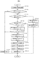
次に、図4のフローチャートを用いて、前記空気ブレーキ使用率算出手段311の内部処理を説明する。本実施例の運転支援システムでは、図4のフローチャートで示される処理が、列車起動中に繰り返し処理され続ける。処理周期は必ずしも一定である必要はないが、0.1〜1.0秒オーダーの分解能で操作されるノッチ操作の運転支援として機能するために十分に短い周期であることが望まれる。 Next, the internal processing of the air brake usage rate calculating means 311 will be described using the flowchart of FIG. In the driving support system of the present embodiment, the processing shown in the flowchart of FIG. 4 is repeatedly processed during train activation. The processing period is not necessarily constant, but it is desirable that the period be sufficiently short to function as driving support for notch operation operated with a resolution of the order of 0.1 to 1.0 seconds.
ステップ(図中では「STEP」)401で、前記ノッチ情報321を取得する。前記ノッチ情報321には、力行/ブレーキの区別、および、ノッチ段数の大きさが含まれる。
In step (“STEP” in the figure) 401, the
ステップ402では、列車が走行中で、かつ、制動中であるか否かの判定を行う。走行中であるか否かは前記列車速度324が所定値以上(例.5km/h)であることを判定条件とする。制動中であるか否かは、前記ノッチ情報321が、ブレーキノッチであることを判定条件とする。ステップ402の判定がYESの場合は、ステップ403へ進み、ステップ402の判定がNOの場合はステップ415へ進む。ステップ415では、前記教示手段313における教示内容をリセットする信号を、前記教示手段313へ出力する。
In
ステップ403では、ブレーキノッチが高位側へ切替えられたか否かを判定する。本判定には前記ノッチ情報321を使用する。具体的には、前回の処理周期の前記ノッチ情報321と今回の処理周期の前記ノッチ情報321のノッチ段数を比較し、後者が前者よりも大きければ、高位切替有りと判定する。高位切替有りの場合はステップ404へ、無しの場合はステップ406へ遷移する。
In step 403, it is determined whether or not the brake notch has been switched to the higher side. The
ステップ404では、ステップ403での判定結果を受けて、高位切替フラグをセットする(flag=1)。また、続くステップ405では、高位切替後タイマをリセットする(timer=0)。前記高位切替フラグは、回生ブレーキが効き始める前に空気ブレーキが介入している時間帯(図2のt1)であることを示すフラグであり、前記高位切替後タイマが所定の閾値(T)に達するまで、1を維持する(初期値=0)。前記高位切替フラグと前記高位切替タイマの挙動例を図5に示す。ステップ405を処理後、本周期を終える。
In
ステップ406では、前記高位切替フラグが立っているか否かを判定し、立っていればステップ407へ進み、立っていなければステップ411へ進む。
In
ステップ407では、前記高位切替後タイマをインクリメントする(timer=timer+dT)。ここで、dTは図4のフローの処理周期である。
In
ステップ407に続くステップ408では、前記高位切替後タイマの値を、所定閾値Tと比較し、timer≧Tであればステップ409へ進み、timer<Tであればステップ415を経て処理を終了する。ここで前記所定閾値Tは、図2に示すt1の時間よりも長く設定される。t1の大きさは、前記回生ブレーキ制御手段308内部の動作で決定されるため、前記回生ブレーキ制御手段308の処理仕様が分かっている場合は理論的に導出できる。例えば、回生ブレーキ力の立ち上げに、1ノッチあたり0.2秒の時間を費やす仕様(ジャーク制御目的が考えられる)のもとで、最大7ノッチ分のノッチ変化が想定される場合にはT>max(t1)=1.4秒で設定されるべきである。
In
一方で、Tが大きくなるほど運転支援が実施される時間が短くなり、省エネ効果が低減するため、Tは必要最小限の大きさにすべきである。そのために、ノッチ変化の大きさに合わせてTを可変にする方法も考えられる。例えば、回生ブレーキ力の立ち上げに、1ノッチあたり0.2秒の時間を費やす仕様(ジャーク制御目的が考えられる)のもとであれば、T>t1=0.2×dNで設定することができる(ここで、dNはノッチ変化の大きさ)。 On the other hand, as T increases, the time during which driving assistance is performed is shortened and the energy saving effect is reduced. Therefore, T should be set to the minimum necessary size. Therefore, a method of making T variable according to the magnitude of the notch change is also conceivable. For example, if it is based on the specification that a time of 0.2 second per notch is consumed for starting up the regenerative braking force (the purpose of jerk control is considered), set T> t1 = 0.2 × dN. (Where dN is the magnitude of the notch change).
ステップ409では、前記高位切替後タイマがリセットされる(timer=0)。また、続くステップ410で、前記高位切替フラグがリセットされる(flag=0)。
In
ステップ411では、前記回生ブレーキ制御手段308から、実回生ブレーキ力329を取得する。
In step 411, the actual
ステップ412では、前記空気ブレーキ力指令算出手段309から、空気ブレーキ力指令328を取得する。
In step 412, an air
ステップ413では、前記実回生ブレーキ力329と前記空気ブレーキ力指令328とから、空気ブレーキ力使用率(割合)を算出する。
In step 413, an air brake force usage rate (ratio) is calculated from the actual
ステップ414では、前記空気ブレーキ力使用率を基に、教示する運転支援内容を決定し、前記教示手段312にセットする。 In step 414, the driving assistance content to be taught is determined based on the air brake force usage rate and set in the teaching means 312.
次に、前記教示手段312における運転支援内容の例を説明する。
Next, an example of driving support contents in the
前記教示手段3122が表示画面である場合の運転支援内容の例を図6と図7に示す。図6は、出力している全ブレーキ力に占める空気ブレーキの仕様率を画面にグラフ表示する例である。図7は、出力している全ブレーキ力の大きさをグラフ表示したうえで、その棒グラフ内で、空気ブレーキ使用率を塗りつぶしなどで示す例である。 Examples of driving support contents when the teaching means 3122 is a display screen are shown in FIGS. FIG. 6 is an example in which the specification rate of the air brake occupying the total braking force being output is displayed in a graph on the screen. FIG. 7 is an example in which the magnitude of the total braking force being output is displayed in a graph, and the air brake usage rate is indicated by filling in the bar graph.
空気ブレーキ使用率の教示方法として、表示だけであなく、音声による教示も可能である。例として、空気ブレーキ使用率が所定閾値(たとえば20%)を超えた場合に、アラーム音や音声メッセージを鳴らす方法である。運転支援の音声化により、画面を見る頻度が減り、前方注視が容易になる。 As a method of teaching the air brake usage rate, not only display but also voice teaching is possible. An example is a method of sounding an alarm sound or a voice message when the air brake usage rate exceeds a predetermined threshold (for example, 20%). Driving support voices reduce the frequency of viewing the screen, making it easier to look forward.
表示・音声鳴動のいずれの場合でも、空気ブレーキ使用率の伝達のみでなく、空気ブレーキ仕様率を低減するための具体的な運転操作を促す情報を付加することで、運転士は支援情報を実運転操作へ反映させやすくなる。 In both cases of display and sound, the driver implements the support information by adding information that encourages specific driving operations to reduce the air brake specification rate as well as the transmission of the air brake usage rate. It becomes easy to reflect in driving operation.
以上が、前記教示手段312における運転支援内容の例である。 The above is an example of the driving assistance contents in the teaching means 312.
以上が、実施例1の説明である。 The above is the description of the first embodiment.
本実施例では、実施例1で算出・教示した空気ブレーキ使用率を、ブレーキ操作時の運転状況とともにデータベース化し、別途設ける読出し手段で、運転業務終了後などに振り返りができる運転支援システムを説明する。本実施例に示す形態では、運転操作の振り返りによる気づきを得て、次回以降の運転業務に活用することで、より効果的な省エネ運転支援につなげることができる。 In the present embodiment, a driving support system is described in which the air brake usage rate calculated and taught in the first embodiment is made into a database together with the driving situation at the time of brake operation, and can be looked back after the end of the driving operation by a reading means provided separately. . In the form shown in the present embodiment, it is possible to obtain more noticed by looking back on the driving operation, and use it for the driving operation after the next time, which can lead to more effective energy saving driving support.
図8は、本実施例の運転支援システム800の構成を示す。前記運転支援システム800は、ノッチ情報321、AS圧322、架線電圧323、列車速度324、列車位置830を入力として、空気ブレーキ使用率データ831を作成し、前記運転支援システム800の構成要素である空気ブレーキ使用率データベース812に蓄積したうえで、読出し手段815で前記空気ブレーキ使用率データベース812から読み出しデータ832を読み出すことができる。
FIG. 8 shows the configuration of the driving
前記ノッチ情報321は、マスコン301から取得する。前記AS圧322はAS圧取得手段302から取得する。前記架線電圧323は架線電圧取得手段303から取得する。前記列車速度324は列車速度取得手段304から取得する。前記列車位置830は、列車位置取得手段810から取得する。前記AS圧取得手段302、前記架線電圧取得手段303、前記列車速度取得手段304、前記列車位置取得手段810は、それぞれ個別の検知手段として列車内に設けてもよい。あるいは、列車内の情報を統括制御する車両情報制御装置(図示しない)から一括して取得する形態であってもよい。
The
前記運転支援システム800の内部は、ブレーキ指令制御手段314と、空気ブレーキ使用率データ活用部813とに分けられる。
The interior of the driving
前記ブレーキ指令制御手段314の構成要素と内部処理は実施例1と同一である。 The components and internal processing of the brake command control means 314 are the same as those in the first embodiment.
次に前記空気ブレーキ使用率データ活用部813の内部の構成手段と処理を説明する。
Next, internal components and processing of the air brake usage rate
前記空気ブレーキ使用率データ活用部813は、空気ブレーキ使用率算出手段311と前記教示手段312とからなる。空気ブレーキ使用率データ算出統合手段811は、前記実回生ブレーキ力329と、前記空気ブレーキ力指令328と、前記ノッチ情報321と、前記列車速度324とを入力として、空気ブレーキ使用率を算出する。前記空気ブレーキ使用率算出の処理は、実施例1で示した図4のステップ401からステップ413と同一である。
The air brake usage rate
それと同時に前記空気ブレーキ使用率データ算出統合手段811は、当該空気ブレーキ使用率となったタイミングにおける運転状況データとして、前記ノッチ情報321と、前記AS圧322と、前記架線電圧323と、前記列車速度324と前記列車位置830とを取得する。前記運転状況データにはこれらに限らない。
At the same time, the air brake usage rate data
前記空気ブレーキ使用率データ算出統合手段811は、前記空気ブレーキ力指令328と前記運転状況データを対応づけて前記空気ブレーキ使用率データ831を作成し、前記空気ブレーキ使用率データベース812に蓄積する。蓄積されたデータは、前記読出し手段815から読出しデータ832として、出力・閲覧できる。
The air brake usage rate data calculation and
以上が、本実施例の運転支援システム800の構成の説明である。
The above is description of the structure of the driving
300 運転支援システム
301 マスコン
302 AS圧取得手段
303 架線電圧取得手段
304 列車速度取得手段
305 必要ブレーキ力算出手段
306 最大回生ブレーキ力算出手段
307 回生ブレーキ力指令算出手段
308 回生ブレーキ制御手段
309 空気ブレーキ力指令算出手段
311 空気ブレーキ使用率算出手段
312 教示手段
313 空気ブレーキ使用率算出教示部
314 ブレーキ指令制御手段
321 ノッチ情報
322 AS圧
323 架線電圧
324 列車速度
325 必要ブレーキ力
326 最大回生ブレーキ力
327 回生ブレーキ力指令
328 空気ブレーキ力指令
329 実回生ブレーキ力
331 教示内容データ
800 運転支援システム
810 列車位置取得手段
811 空気ブレーキ使用率データ算出統合手段
812 空気ブレーキ使用率データベース
813 空気ブレーキ使用率データ活用部
815 読出し手段
830 列車位置
831 空気ブレーキ使用率データ
832 読出しデータ
300 driving
Claims (16)
前記空気ブレーキ使用率算出手段は、主幹制御器を介して運転士から入力されたノッチ情報と、列車速度取得手段により検出された列車速度とに基づいて、前記空気ブレーキ使用率の算出タイミングを決定すること、
を特徴とする運転支援システム。 Brake command control means for calculating an air brake force command value for a railway vehicle, and an air brake use rate calculation means for calculating an air brake use ratio from the air brake force command value and the actual output regenerative brake force actual value And a driving support system comprising teaching means for teaching the crew member the air brake usage rate,
The air brake usage rate calculating means determines the calculation timing of the air brake usage rate based on notch information input from the driver via the master controller and the train speed detected by the train speed acquisition means. To do,
A driving assistance system characterized by
前記空気ブレーキ使用率算出手段は、前記ノッチ情報がブレーキ側であり、かつ前記列車速度が正であるときに前記空気ブレーキ使用率を算出すること、
を特徴とする運転支援システム。 The driving support system according to claim 1,
The air brake usage rate calculating means calculates the air brake usage rate when the notch information is on the brake side and the train speed is positive;
A driving assistance system characterized by
前記空気ブレーキ使用率算出手段は、前記ノッチ情報が高位側へ変化したタイミングから一定の所定時間後より、前記空気ブレーキ使用率を算出すること、
を特徴とする運転支援システム。 The driving support system according to claim 2,
The air brake usage rate calculating means calculates the air brake usage rate after a predetermined time from the timing when the notch information is changed to the higher side;
A driving assistance system characterized by
前記空気ブレーキ使用率算出手段は、前記ノッチ情報が高位側へ変化したタイミングから可変の所定時間後より、前記空気ブレーキ使用率を算出すること、
を特徴とする運転支援システム。 The driving support system according to claim 2,
The air brake usage rate calculating means calculates the air brake usage rate after a predetermined variable time from the timing when the notch information is changed to the higher side.
A driving assistance system characterized by
前記可変の所定時間は、前記ノッチ情報が高位側へ変化した際の変化量が大きいほど長くなること、
を特徴とする運転支援システム。 The driving support system according to claim 4,
The variable predetermined time becomes longer as the amount of change when the notch information is changed to a higher side is larger,
A driving assistance system characterized by
前記教示手段は前記空気ブレーキ使用率を画面表示で教示すること、
を特徴とする運転支援システム。 The driving support system according to any one of claims 1 to 6,
The teaching means teaches the air brake usage rate on a screen display;
A driving assistance system characterized by
前記教示手段は、前記空気ブレーキ使用率とともに、前記空気ブレーキ力指令値と前記回生ブレーキ力実績値の和である、要求ブレーキ力を同画面に画面表示すること、
を特徴とする運転支援システム。 The driving support system according to claim 6,
The teaching means displays the required brake force on the same screen, which is the sum of the air brake force command value and the regenerative brake force actual value together with the air brake usage rate,
A driving assistance system characterized by
前記教示手段は、前記空気ブレーキ使用率を音声鳴動で教示すること、
を特徴とする運転支援システム。 The driving support system according to any one of claims 1 to 6,
The teaching means teaches the air brake usage rate by sounding sound,
A driving assistance system characterized by
前記教示手段は、前記空気ブレーキ使用率が所定の閾値を超えた場合に音声鳴動すること、
を特徴とする運転支援システム。 The driving support system according to claim 8, wherein
The teaching means sounds when the air brake usage rate exceeds a predetermined threshold;
A driving assistance system characterized by
前記教示手段は、前記空気ブレーキ使用率を下げる運転操作ガイダンスを音声鳴動に含むこと、
を特徴とする運転支援システム。 The driving support system according to claim 9,
The teaching means includes a driving operation guidance for reducing the air brake usage rate in a sounding sound,
A driving assistance system characterized by
を特徴とする運転支援システム。 11. The driving support system according to claim 1, wherein the teaching content from the teaching unit is erased while the air brake usage rate calculating unit does not calculate the air brake usage rate. Being
A driving assistance system characterized by
前記空気ブレーキ使用率データ算出統合手段は、主幹制御器を介して運転士から入力されたノッチ情報と、列車速度取得手段により検出された列車速度とに基づいて、前記空気ブレーキ使用率の算出タイミングを決定すること、
を特徴とする運転支援システム。 The brake command control means for calculating the air brake force command value of the railway vehicle, the air brake use ratio is calculated from the air brake force command value and the actual output value of the regenerative brake force, and both the operation status data and air An operation support system comprising air brake usage rate data calculation integration means for creating brake usage rate data, an air brake usage rate database for storing the air brake usage rate data, and a reading means for reading out the air usage rate data,
The air brake usage rate data calculation integration unit is configured to calculate the air brake usage rate based on the notch information input from the driver via the master controller and the train speed detected by the train speed acquisition unit. To determine the
A driving assistance system characterized by
前記空気ブレーキ使用率算出手段は、前記ノッチ情報がブレーキ側であり、かつ前記列車速度が正であるときに前記空気ブレーキ使用率を算出すること、
を特徴とする運転支援システム。 The driving support system according to claim 12, wherein
The air brake usage rate calculating means calculates the air brake usage rate when the notch information is on the brake side and the train speed is positive;
A driving assistance system characterized by
前記空気ブレーキ使用率算出手段は、前記ノッチ情報が高位側へ変化したタイミングから一定の所定時間後より、前記空気ブレーキ使用率を算出すること、
を特徴とする運転支援システム。 The driving support system according to claim 13,
The air brake usage rate calculating means calculates the air brake usage rate after a predetermined time from the timing when the notch information is changed to the higher side;
A driving assistance system characterized by
前記空気ブレーキ使用率算出手段は、前記ノッチ情報が高位側へ変化したタイミングから可変の所定時間後より、前記空気ブレーキ使用率を算出すること、
を特徴とする運転支援システム。 The driving support system according to claim 13,
The air brake usage rate calculating means calculates the air brake usage rate after a predetermined variable time from the timing when the notch information is changed to the higher side.
A driving assistance system characterized by
前記可変の所定時間は、前記ノッチ情報が高位側へ変化した際の変化量が大きいほど長くなること、
を特徴とする運転支援システム。 The driving support system according to claim 15,
The variable predetermined time becomes longer as the amount of change when the notch information is changed to a higher side is larger,
A driving assistance system characterized by
Priority Applications (1)
| Application Number | Priority Date | Filing Date | Title |
|---|---|---|---|
| JP2016097569A JP6663791B2 (en) | 2016-05-16 | 2016-05-16 | Driving support system |
Applications Claiming Priority (1)
| Application Number | Priority Date | Filing Date | Title |
|---|---|---|---|
| JP2016097569A JP6663791B2 (en) | 2016-05-16 | 2016-05-16 | Driving support system |
Publications (2)
| Publication Number | Publication Date |
|---|---|
| JP2017208868A true JP2017208868A (en) | 2017-11-24 |
| JP6663791B2 JP6663791B2 (en) | 2020-03-13 |
Family
ID=60416699
Family Applications (1)
| Application Number | Title | Priority Date | Filing Date |
|---|---|---|---|
| JP2016097569A Active JP6663791B2 (en) | 2016-05-16 | 2016-05-16 | Driving support system |
Country Status (1)
| Country | Link |
|---|---|
| JP (1) | JP6663791B2 (en) |
Cited By (2)
| Publication number | Priority date | Publication date | Assignee | Title |
|---|---|---|---|---|
| JP2021071806A (en) * | 2019-10-29 | 2021-05-06 | トヨタ自動車株式会社 | Information processing device, information processing method, and information processing program |
| CN113548090A (en) * | 2021-09-23 | 2021-10-26 | 北京和利时系统工程有限公司 | Method and device for adjusting accurate parking control parameters of train automatic driving |
-
2016
- 2016-05-16 JP JP2016097569A patent/JP6663791B2/en active Active
Cited By (4)
| Publication number | Priority date | Publication date | Assignee | Title |
|---|---|---|---|---|
| JP2021071806A (en) * | 2019-10-29 | 2021-05-06 | トヨタ自動車株式会社 | Information processing device, information processing method, and information processing program |
| JP7172948B2 (en) | 2019-10-29 | 2022-11-16 | トヨタ自動車株式会社 | Information processing device, information processing method, and information processing program |
| CN113548090A (en) * | 2021-09-23 | 2021-10-26 | 北京和利时系统工程有限公司 | Method and device for adjusting accurate parking control parameters of train automatic driving |
| CN113548090B (en) * | 2021-09-23 | 2021-12-28 | 北京和利时系统工程有限公司 | Method and device for adjusting accurate parking control parameters of train automatic driving |
Also Published As
| Publication number | Publication date |
|---|---|
| JP6663791B2 (en) | 2020-03-13 |
Similar Documents
| Publication | Publication Date | Title |
|---|---|---|
| KR100942093B1 (en) | Brake control device for electric vehicle | |
| US9067589B1 (en) | Hybrid powertrain mode determination based on spatial domain route segmentation | |
| JP5991220B2 (en) | Driving assistance device | |
| JP5983885B2 (en) | Vehicle regenerative braking control device | |
| JP2015104230A (en) | Drive control device for movable body | |
| KR20090126197A (en) | Control device of electric vehicle provided with fixed position automatic stop control means | |
| KR102177284B1 (en) | Control method of motor on caliper based on calculated disc temperature | |
| JP5869150B2 (en) | Travel plan creation device, driving support device, and driving control device | |
| JP2002120702A (en) | Braking position proximity warning device and automatic brake device | |
| KR20170051443A (en) | Method and device for operating a motor vehicle, motor vehicle | |
| JP2017208868A (en) | Operation support system | |
| CN107235053B (en) | Heavy haul train descending automatic Pilot method based on movable block | |
| RU2666499C1 (en) | Vehicle operation method | |
| JP6855178B2 (en) | A method for driving a vehicle-specific braking system with an electric motor, and a control device for at least one electric motor of the vehicle-specific braking system. | |
| CN107539298B (en) | Method and system for controlling air brake of train | |
| JP6186619B2 (en) | Electric vehicle stop lamp lighting control device | |
| US20200108722A1 (en) | Operating procedure for a brake system, brake system and motor vehicle | |
| CN112721893A (en) | Electric-air-matched parking control method and system, storage medium, equipment and vehicle | |
| JP5384440B2 (en) | Train schedule creation support device | |
| TW201641330A (en) | Brake control device of railway vehicle | |
| JP2007060867A (en) | Brake controller for railway vehicle | |
| JP2008187761A (en) | Train control device | |
| CN111406006B (en) | Method for controlling a brake system of at least one rail vehicle | |
| JP2005280542A (en) | Atc/o device | |
| GB2483477A (en) | Control of regenerative and friction braking |
Legal Events
| Date | Code | Title | Description |
|---|---|---|---|
| RD04 | Notification of resignation of power of attorney |
Free format text: JAPANESE INTERMEDIATE CODE: A7424 Effective date: 20170111 |
|
| RD04 | Notification of resignation of power of attorney |
Free format text: JAPANESE INTERMEDIATE CODE: A7424 Effective date: 20170113 |
|
| A621 | Written request for application examination |
Free format text: JAPANESE INTERMEDIATE CODE: A621 Effective date: 20180907 |
|
| A131 | Notification of reasons for refusal |
Free format text: JAPANESE INTERMEDIATE CODE: A131 Effective date: 20191008 |
|
| RD02 | Notification of acceptance of power of attorney |
Free format text: JAPANESE INTERMEDIATE CODE: A7422 Effective date: 20191105 |
|
| RD04 | Notification of resignation of power of attorney |
Free format text: JAPANESE INTERMEDIATE CODE: A7424 Effective date: 20191114 |
|
| A521 | Written amendment |
Free format text: JAPANESE INTERMEDIATE CODE: A523 Effective date: 20191205 |
|
| TRDD | Decision of grant or rejection written | ||
| A01 | Written decision to grant a patent or to grant a registration (utility model) |
Free format text: JAPANESE INTERMEDIATE CODE: A01 Effective date: 20200212 |
|
| A61 | First payment of annual fees (during grant procedure) |
Free format text: JAPANESE INTERMEDIATE CODE: A61 Effective date: 20200217 |
|
| R150 | Certificate of patent or registration of utility model |
Ref document number: 6663791 Country of ref document: JP Free format text: JAPANESE INTERMEDIATE CODE: R150 |