JP2017208583A - Terminal device and base station device - Google Patents
Terminal device and base station device Download PDFInfo
- Publication number
- JP2017208583A JP2017208583A JP2014197765A JP2014197765A JP2017208583A JP 2017208583 A JP2017208583 A JP 2017208583A JP 2014197765 A JP2014197765 A JP 2014197765A JP 2014197765 A JP2014197765 A JP 2014197765A JP 2017208583 A JP2017208583 A JP 2017208583A
- Authority
- JP
- Japan
- Prior art keywords
- cell
- drs
- secondary cell
- terminal device
- measurement
- Prior art date
- Legal status (The legal status is an assumption and is not a legal conclusion. Google has not performed a legal analysis and makes no representation as to the accuracy of the status listed.)
- Pending
Links
Images


Classifications
-
- H—ELECTRICITY
- H04—ELECTRIC COMMUNICATION TECHNIQUE
- H04W—WIRELESS COMMUNICATION NETWORKS
- H04W16/00—Network planning, e.g. coverage or traffic planning tools; Network deployment, e.g. resource partitioning or cells structures
- H04W16/24—Cell structures
- H04W16/32—Hierarchical cell structures
-
- H—ELECTRICITY
- H04—ELECTRIC COMMUNICATION TECHNIQUE
- H04W—WIRELESS COMMUNICATION NETWORKS
- H04W48/00—Access restriction; Network selection; Access point selection
- H04W48/08—Access restriction or access information delivery, e.g. discovery data delivery
-
- H—ELECTRICITY
- H04—ELECTRIC COMMUNICATION TECHNIQUE
- H04W—WIRELESS COMMUNICATION NETWORKS
- H04W52/00—Power management, e.g. TPC [Transmission Power Control], power saving or power classes
- H04W52/02—Power saving arrangements
-
- H—ELECTRICITY
- H04—ELECTRIC COMMUNICATION TECHNIQUE
- H04W—WIRELESS COMMUNICATION NETWORKS
- H04W72/00—Local resource management
- H04W72/04—Wireless resource allocation
-
- H—ELECTRICITY
- H04—ELECTRIC COMMUNICATION TECHNIQUE
- H04W—WIRELESS COMMUNICATION NETWORKS
- H04W84/00—Network topologies
- H04W84/02—Hierarchically pre-organised networks, e.g. paging networks, cellular networks, WLAN [Wireless Local Area Network] or WLL [Wireless Local Loop]
- H04W84/10—Small scale networks; Flat hierarchical networks
-
- Y—GENERAL TAGGING OF NEW TECHNOLOGICAL DEVELOPMENTS; GENERAL TAGGING OF CROSS-SECTIONAL TECHNOLOGIES SPANNING OVER SEVERAL SECTIONS OF THE IPC; TECHNICAL SUBJECTS COVERED BY FORMER USPC CROSS-REFERENCE ART COLLECTIONS [XRACs] AND DIGESTS
- Y02—TECHNOLOGIES OR APPLICATIONS FOR MITIGATION OR ADAPTATION AGAINST CLIMATE CHANGE
- Y02D—CLIMATE CHANGE MITIGATION TECHNOLOGIES IN INFORMATION AND COMMUNICATION TECHNOLOGIES [ICT], I.E. INFORMATION AND COMMUNICATION TECHNOLOGIES AIMING AT THE REDUCTION OF THEIR OWN ENERGY USE
- Y02D30/00—Reducing energy consumption in communication networks
- Y02D30/70—Reducing energy consumption in communication networks in wireless communication networks
Abstract
Description
本発明は、端末装置、および、基地局装置に関する。 The present invention relates to a terminal device and a base station device.
セルラー移動通信の無線アクセス方式および無線ネットワーク(以下、「Long Term Evolution (LTE)」、または、「Evolved Universal Terrestrial Radio Access : EUTRA」と称する。)が、第三世代パートナーシッププロジェクト(3rd Generation Partnership Project: 3GPP)において検討されている。LTEでは、基地局装置(基地局)をeNodeB(evolved NodeB)、端末装置(移動局、移動局装置、端末)をUE(User Equipment)とも称する。LTEは、基地局装置がカバーするエリアをセル状に複数配置するセルラー通信システムである。単一の基地局装置は複数のセルを管理してもよい。 The wireless access method and wireless network for cellular mobile communications (hereinafter referred to as “Long Term Evolution (LTE)” or “Evolved Universal Terrestrial Radio Access: EUTRA”) is a 3rd Generation Partnership Project: 3GPP). In LTE, a base station device (base station) is also called eNodeB (evolved NodeB), and a terminal device (mobile station, mobile station device, terminal) is also called UE (User Equipment). LTE is a cellular communication system in which a plurality of areas covered by a base station apparatus are arranged in a cell shape. A single base station apparatus may manage a plurality of cells.
LTEは、周波数分割複信(Frequency Division Duplex: FDD)および時分割複信(Time Division Duplex: TDD)に対応している。FDD方式を採用したLTEをFD−LTEまたはLTE FDDとも称する。TDDは、上りリンク信号と下りリンク信号を周波数分割多重することによって、少なくとも2つの周波数帯域において全二重通信を可能にする技術である。TDD方式を採用したLTEをTD−LTEまたはLTE TDDとも称する。TDDは、上りリンク信号と下りリンク信号を時分割多重することによって、単一の周波数帯域において全二重通信を可能にする技術である。FD−LTEおよびTD−LTEの詳細は、非特許文献1に開示されている。
LTE corresponds to Frequency Division Duplex (FDD) and Time Division Duplex (TDD). LTE employing the FDD scheme is also referred to as FD-LTE or LTE FDD. TDD is a technology that enables full-duplex communication in at least two frequency bands by frequency division multiplexing an uplink signal and a downlink signal. LTE employing the TDD scheme is also referred to as TD-LTE or LTE TDD. TDD is a technology that enables full-duplex communication in a single frequency band by time-division multiplexing uplink signals and downlink signals. The details of FD-LTE and TD-LTE are disclosed in
また、基地局装置は、端末装置に対して、基地局装置と端末装置との間において既知の信号である参照信号(RS;Reference Signalとも呼称される)を送信できる。この参照信号は、信号やチャネルの復調やチャネル状態のレポートなどの様々な目的のために、複数の参照信号を送信できる。例えば、セル固有参照信号は、セルに固有の参照信号として、全ての下りリンクサブフレームにおいて送信される。また、例えば、端末固有参照信号は、端末装置に固有の参照信号として、その端末装置に対するデータ信号がマッピングされるリソースにおいて送信される。参照信号の詳細は、非特許文献1に開示されている。
Further, the base station device can transmit a reference signal (also referred to as RS; Reference Signal), which is a known signal, between the base station device and the terminal device to the terminal device. This reference signal can transmit multiple reference signals for various purposes such as signal and channel demodulation and channel state reporting. For example, the cell-specific reference signal is transmitted in all downlink subframes as a cell-specific reference signal. Also, for example, the terminal-specific reference signal is transmitted as a reference signal specific to the terminal apparatus in a resource to which a data signal for the terminal apparatus is mapped. Details of the reference signal are disclosed in
3GPPにおいて、小セル(Small Cell)の導入が検討される。小セルとは、セルを構成する基地局装置の送信電力が小さく、従来のセル(マクロセル)に比べてカバレッジの小さなセルの総称である。例えば、小セルを高周波数帯で適用することで、高密度に小セルを配置することが可能となり、面積あたりの周波数利用効率を向上させる効果がある。小セルの導入検討では、低消費電力化やセル間干渉低減などの様々な目的のために、基地局装置を停止の状態に切り替える技術が検討されている。詳細は、非特許文献2に開示されている。
In 3GPP, introduction of a small cell is considered. A small cell is a generic term for a cell having a small transmission power of a base station apparatus constituting the cell and having a smaller coverage than a conventional cell (macro cell). For example, by applying small cells in a high frequency band, it is possible to arrange small cells with high density, and there is an effect of improving the frequency utilization efficiency per area. In consideration of introduction of a small cell, a technique for switching a base station apparatus to a stopped state is being studied for various purposes such as low power consumption and inter-cell interference reduction. Details are disclosed in Non-Patent
しかしながら、基地局装置を停止の状態に切り替えた場合において、同期信号や参照信号の送信も停止され、端末装置は停止の状態の基地局装置を発見することが困難となる。このような状況において、停止の状態の基地局装置に端末装置が接続する際に多くの準備時間が掛かってしまうため、伝送効率を大幅に劣化させる要因となる。 However, when the base station apparatus is switched to the stopped state, the transmission of the synchronization signal and the reference signal is also stopped, and it becomes difficult for the terminal apparatus to find the stopped base station apparatus. In such a situation, it takes a lot of preparation time when the terminal apparatus is connected to the base station apparatus in a stopped state, which causes a significant deterioration in transmission efficiency.
本発明は、上記問題を鑑みてなされたものであり、その目的は、基地局装置と端末装置が通信する通信システムにおいて、伝送効率を向上させることができる基地局装置、端末装置、通信システム、通信方法および集積回路を提供することにある。 The present invention has been made in view of the above problems, and an object of the present invention is to provide a base station device, a terminal device, a communication system, and a communication system in which a base station device and a terminal device communicate with each other. To provide a communication method and an integrated circuit.
(1)上記の目的を達成するために、本発明は、以下のような手段を講じた。すなわち、本実施形態の端末装置は、第1のセカンダリーセルアクティベーションタイミングと、第2のセカンダリーセルアクティベーションタイミングの切り替えに関連する所定の上位層パラメータを受信することを特徴としている。 (1) In order to achieve the above object, the present invention takes the following measures. That is, the terminal device according to the present embodiment is characterized by receiving a predetermined higher layer parameter related to switching between the first secondary cell activation timing and the second secondary cell activation timing.
(2)また、本実施形態の端末装置において、前記上位層パラメータを受信した場合、セカンダリーセルのセカンダリーセルアクティベーションタイミングを、第1のセカンダリーセルアクティベーションタイミングから第2のセカンダリーセルアクティベーションタイミングに切り換える。 (2) Moreover, in the terminal device of this embodiment, when the upper layer parameter is received, the secondary cell activation timing of the secondary cell is changed from the first secondary cell activation timing to the second secondary cell activation timing. Switch.
(3)また、本実施形態の端末装置において、前記上位層パラメータを受信した場合、セカンダリーセルのアクティベーションに加え、前記セカンダリーセルのON/OFF(起動/停止)が適用される。 (3) Moreover, in the terminal device of this embodiment, when the upper layer parameter is received, ON / OFF (start / stop) of the secondary cell is applied in addition to the activation of the secondary cell.
(4)また、本実施形態の端末装置において、前記上位層パラメータを受信した場合、セカンダリーセルのアクティベーション/デアクティベーションを、前記セカンダリーセルのON/OFF(起動/停止)に切り替える。 (4) Moreover, in the terminal device of this embodiment, when the upper layer parameter is received, the activation / deactivation of the secondary cell is switched to ON / OFF (start / stop) of the secondary cell.
この発明によれば、基地局装置と端末装置が通信する無線通信システムにおいて、伝送効率を向上させることができる。 According to the present invention, transmission efficiency can be improved in a wireless communication system in which a base station device and a terminal device communicate.
以下、本発明の実施形態について説明する。 Hereinafter, embodiments of the present invention will be described.
本実施形態において、端末装置1は、複数のセルが設定されてもよい。ここで、端末装置1が、複数のセルを介して通信する技術をセルアグリゲーション、キャリアアグリゲーション、またはデュアルコネクティビティと称する。端末装置1に対して設定される複数のセルのそれぞれにおいて、本発明が適用されてもよい。また、設定された複数のセルの一部において、本発明が適用されてもよい。端末装置1に設定されるセルを、サービングセルとも称する。
In the present embodiment, the
キャリアアグリゲーション(CA)において、設定された複数のサービングセルは、1つのプライマリーセル(PCell: Primary Cell)と1つまたは複数のセカンダリーセル(SCell: Secondary Cell)とを含む。 In the carrier aggregation (CA), the set plurality of serving cells include one primary cell (PCell: Primary Cell) and one or more secondary cells (SCell: Secondary Cell).
プライマリーセルは、初期コネクション構築(initial connection establishment)プロシージャが行なわれたサービングセル、コネクション再構築(connection re-establishment)プロシージャを開始したサービングセル、または、ハンドオーバプロシージャにおいてプライマリーセルと指示されたセルである。プライマリーセルは、プライマリー周波数でオペレーションする。コネクションが(再)構築された時点、または、その後に、セカンダリーセルが設定されてもよい。セカンダリーセルは、セカンダリー周波数でオペレーションする。なお、コネクションは、RRCコネクションと称されてもよい。 The primary cell is a serving cell in which an initial connection establishment procedure has been performed, a serving cell that has started a connection re-establishment procedure, or a cell designated as a primary cell in a handover procedure. The primary cell operates at the primary frequency. A secondary cell may be set at the time when the connection is (re) built or afterwards. The secondary cell operates at the secondary frequency. The connection may be referred to as an RRC connection.
CAをサポートしている端末装置1に対して、1つのプライマリーセルと1つ以上のセカンダリーセルで集約される。
The
デュアルコネクティビティ(Dual Connectivity)とは、少なくとも二つの異なるネットワークポイント(マスター基地局装置(MeNB: Master eNB)とセカンダリー基地局装置(SeNB: Secondary eNB))から提供される無線リソースを所定の端末装置1が消費するオペレーションである。言い換えると、デュアルコネクティビティは、端末装置1が、少なくとも2つのネットワークポイントでRRC接続を行なうことである。デュアルコネクティビティにおいて、端末装置1は、RRC接続(RRC_CONNECTED)状態で、且つ、非理想的バックホール(non-ideal backhaul)によって接続されてもよい。
Dual connectivity refers to radio resources provided from at least two different network points (a master base station device (MeNB: Master eNB) and a secondary base station device (SeNB: Secondary eNB)) in a
デュアルコネクティビティにおいて、少なくともS1−MME(Mobility Management Entity)に接続され、コアネットワークのモビリティアンカーの役割を果たす基地局装置3をマスター基地局装置と称される。また、端末装置1に対して追加の無線リソースを提供するマスター基地局装置ではない基地局装置3をセカンダリー基地局装置と称される。マスター基地局装置に関連されるサービングセルのグループをマスターセルグループ(MCG: Master Cell Group)、セカンダリー基地局装置に関連されるサービングセルのグループをセカンダリーセルグループ(SCG: Secondary Cell Group)と称される場合もある。
In the dual connectivity, the
デュアルコネクティビティにおいて、プライマリーセルは、MCGに属する。また、SCGにおいて、プライマリーセルに相当するセカンダリーセルをプライマリーセカンダリーセル(pSCell: Primary Secondary Cell)と称する。なお、pSCellをスペシャルセルやスペシャルセカンダリーセル(Special SCell: Special Secondary Cell)と称する場合もある。スペシャルSCell(スペシャルSCellを構成する基地局装置)には、PCell(PCellを構成する基地局装置)と同等の機能(能力、性能)がサポートされてもよい。また、pSCellには、PCellの一部の機能だけがサポートされてもよい。例えば、pSCellには、PDCCHを送信する機能がサポートされてもよい。また、pSCellには、CSSまたはUSSとは異なるサーチスペースを用いて、PDCCH送信を行なう機能がサポートされてもよい。例えば、USSとは異なるサーチスペースは、仕様で規定された値に基づいて決まるサーチスペース、C−RNTIとは異なるRNTIに基づいて決まるサーチスペースなどである。また、pSCellは、常に、起動の状態であってもよい。また、pSCellは、PUCCHを受信できるセルである。 In dual connectivity, the primary cell belongs to the MCG. In SCG, a secondary cell corresponding to a primary cell is referred to as a primary secondary cell (pSCell: Primary Secondary Cell). The pSCell may be referred to as a special cell or a special secondary cell (Special SCell). The special SCell (base station apparatus configuring the special SCell) may support functions (capability, performance) equivalent to PCell (base station apparatus configuring the PCell). Moreover, only some functions of PCell may be supported by pSCell. For example, the pSCell may support a function of transmitting PDCCH. In addition, the pSCell may support a function of performing PDCCH transmission using a search space different from CSS or USS. For example, a search space different from USS is a search space determined based on a value defined in the specification, a search space determined based on an RNTI different from C-RNTI, and the like. Further, the pSCell may always be in an activated state. Moreover, pSCell is a cell which can receive PUCCH.
デュアルコネクティビティにおいて、無線ベアラ(データ無線ベアラ(DRB: Data Radio Bearer)および/またはシグナリング無線ベアラ(SRB: Signalling Radio Bearer))は、MeNBとSeNBで個別に割り当てられてもよい。 In dual connectivity, radio bearers (Data Radio Bearer (DRB) and / or Signaling Radio Bearer (SRB)) may be individually allocated in MeNB and SeNB.
デュアルコネクティビティにおいて、MCGとSCGまたはPCellとpSCellでは、それぞれ個別にデュプレックスモードが設定されてもよい。 In dual connectivity, duplex modes may be set individually for MCG and SCG or PCell and pSCell, respectively.
デュアルコネクティビティにおいて、MCGとSCGまたはPCellとpSCellで、同期されなくてもよい。 In dual connectivity, MCG and SCG or PCell and pSCell may not be synchronized.
デュアルコネクティビティにおいて、MCGとSCG(またはPCellとpSCell)それぞれにおいて、複数のタイミング調整のためのパラメータ(TAG: Timing Advancce Group)が設定されてもよい。つまり、MCGとSCG間において、同期されなくてもよい。 In dual connectivity, a plurality of timing adjustment parameters (TAG: Timing Advance Group) may be set in each of MCG and SCG (or PCell and pSCell). That is, there is no need to synchronize between the MCG and the SCG.
デュアルコネクティビティにおいて、端末装置1は、MCG内のセルに対応するUCIは、MeNB(PCell)のみに送信し、SCG内のセルに対応するUCIは、SeNB(pSCell)のみに送信する。例えば、UCIはSR、HARQ−ACK、および/またはCSIである。また、それぞれのUCIの送信において、PUCCHおよび/またはPUSCHを用いた送信方法はそれぞれのセルグループで適用される。
In the dual connectivity, the
プライマリーセルでは、すべての信号が送受信可能であるが、セカンダリーセルでは、送受信できない信号がある。例えば、PUCCH(Physical Uplink Control Channel)は、プライマリーセルでのみ送信される。また、PRACH(Physical Random Access Channel)は、セル間で、複数のTAG(Timing Advance Group)が設定されない限り、プライマリーセルでのみ送信される。また、PBCH(Physical Broadcast Channel)は、プライマリーセルでのみ送信される。また、MIB(Master Information Block)は、プライマリーセルでのみ送信される。 All signals can be transmitted and received in the primary cell, but there are signals that cannot be transmitted and received in the secondary cell. For example, PUCCH (Physical Uplink Control Channel) is transmitted only in the primary cell. Also, PRACH (Physical Random Access Channel) is transmitted only in the primary cell unless a plurality of TAGs (Timing Advance Groups) are set between cells. A PBCH (Physical Broadcast Channel) is transmitted only in the primary cell. Also, the MIB (Master Information Block) is transmitted only in the primary cell.
プライマリーセカンダリーセルでは、プライマリーセルで送受信可能な信号が送受信される。例えば、PUCCHは、プライマリーセカンダリーセルで送信されてもよい。また、PRACHは、複数のTAGが設定されているかにかかわらず、プライマリーセカンダリーセルで送信されてもよい。また、PBCHやMIBがプライマリーセカンダリーセルで送信されてもよい。 In the primary secondary cell, signals that can be transmitted and received in the primary cell are transmitted and received. For example, PUCCH may be transmitted by a primary secondary cell. Moreover, PRACH may be transmitted by a primary secondary cell irrespective of whether several TAG is set. Moreover, PBCH and MIB may be transmitted by a primary secondary cell.
プライマリーセルでは、RLF(Radio Link Failure)が検出される。セカンダリーセルでは、RLFが検出される条件が整ってもRLFが検出されたと認識しない。プライマリーセカンダリーセルでは、条件を満たせば、RLFが検出される。プライマリーセカンダリーセルにおいて、RLFが検出された場合、プライマリーセカンダリーセルの上位層は、プライマリーセルの上位層へRLFが検出されたことを通知する。 In the primary cell, RLF (Radio Link Failure) is detected. The secondary cell does not recognize that RLF has been detected even if the conditions for detecting RLF are met. In the primary secondary cell, the RLF is detected if the condition is satisfied. When the RLF is detected in the primary secondary cell, the upper layer of the primary secondary cell notifies the upper layer of the primary cell that the RLF has been detected.
プライマリーセルおよび/またはプライマリーセカンダリーセルでは、SPS(Semi-Persistent Scheduling)やDRX(Discontinuous Transmission)を行なってもよい。SPS設定とDRX設定の総数は、プライマリーセルとプライマリーセカンダリーセルの総数で決定されてもよい。セカンダリーセルでは、同じセルグループのプライマリーセルまたはプライマリーセカンダリーセルと同じDRXを行なってもよい。 In the primary cell and / or the primary secondary cell, SPS (Semi-Persistent Scheduling) or DRX (Discontinuous Transmission) may be performed. The total number of SPS settings and DRX settings may be determined by the total number of primary cells and primary secondary cells. The secondary cell may perform the same DRX as the primary cell or primary secondary cell of the same cell group.
セカンダリーセルにおいて、MACの設定に関する情報/パラメータは、基本的に、同じセルグループのプライマリーセル/プライマリーセカンダリーセルと共有している。一部のパラメータ(例えば、sTAG-Id)は、セカンダリーセル毎に設定されてもよい。 In the secondary cell, information / parameters related to MAC settings are basically shared with the primary cell / primary secondary cell of the same cell group. Some parameters (for example, sTAG-Id) may be set for each secondary cell.
一部のタイマーやカウンタが、プライマリーセルおよび/またはプライマリーセカンダリーセルに対してのみ適用されてもよい。セカンダリーセルに対してのみ、適用されるタイマーやカウンタが設定されてもよい。 Some timers and counters may be applied only to the primary cell and / or the primary secondary cell. A timer or counter that is applied only to the secondary cell may be set.
本実施形態の無線通信システムは、FDD(Frequency Division Duplex)またはTDD(Time Division Duplex)方式のフレーム構成タイプ(Frame Structure Type)が適用される。なお、フレーム構成タイプは、フレーム構造タイプやデュプレックスモードと称される場合もある。セルアグリゲーションの場合には、複数のセルの全てに対してTDD方式が適用されてもよい。また、セルアグリゲーションの場合には、TDD方式が適用されるセルとFDD方式が適用されるセルが集約されてもよい。TDDが適用されるセルとFDDが適用されるセルとが集約される場合に、TDDが適用されるセルに対して本発明を適用することができる。 In the wireless communication system of the present embodiment, a FDD (Frequency Division Duplex) or TDD (Time Division Duplex) frame structure type (Frame Structure Type) is applied. The frame configuration type may be referred to as a frame structure type or a duplex mode. In the case of cell aggregation, the TDD scheme may be applied to all of a plurality of cells. In the case of cell aggregation, cells to which the TDD scheme is applied and cells to which the FDD scheme is applied may be aggregated. When cells to which TDD is applied and cells to which FDD is applied are aggregated, the present invention can be applied to cells to which TDD is applied.
FDDが適用されるセルにおいて、半二重(half-duplex)FDD方式または全二重(full-duplex)FDD方式が適用されてもよい。 In a cell to which FDD is applied, a half-duplex FDD scheme or a full-duplex FDD scheme may be applied.
TDDが適用される複数のセルがアグリゲートされる場合には、半二重(half-duplex)TDD方式または全二重(full-duplex)TDD方式が適用されてもよい。 When a plurality of cells to which TDD is applied are aggregated, a half-duplex TDD scheme or a full-duplex TDD scheme may be applied.
端末装置1は、端末装置1によってキャリアアグリゲーションがサポートされているバンドの組合せを示す情報を、基地局装置3に送信する。端末装置1は、バンドの組合せのそれぞれに対して、異なる複数のバンドにおける前記複数のサービングセルにおける同時送信および受信をサポートしているかどうかを指示する情報を、基地局装置3に送信する。
The
本実施形態において、“X/Y”は、“XまたはY”の意味を含む。本実施形態において、“X/Y”は、“XおよびY”の意味を含む。本実施形態において、“X/Y”は、“Xおよび/またはY”の意味を含む。 In the present embodiment, “X / Y” includes the meaning of “X or Y”. In the present embodiment, “X / Y” includes the meanings of “X and Y”. In the present embodiment, “X / Y” includes the meaning of “X and / or Y”.
図1は、本実施形態の無線通信システムの概念図である。図1において、無線通信システムは、端末装置1A〜1C、および基地局装置3を具備する。以下、端末装置1A〜1Cを端末装置1という。
FIG. 1 is a conceptual diagram of the wireless communication system of the present embodiment. In FIG. 1, the wireless communication system includes terminal apparatuses 1A to 1C and a
本実施形態の物理チャネルおよび物理信号について説明する。 The physical channel and physical signal of this embodiment will be described.
図1において、端末装置1から基地局装置3への上りリンクの無線通信では、上りリンク物理チャネルが用いられる。上りリンク物理チャネルは、上位層から出力された情報を送信するために使用できる。上りリンク物理チャネルは、PUCCH(Physical Uplink Control Channel)、PUSCH(Physical Uplink Shared Channel)、PRACH(Physical Random Access Channel)などを含む。
In FIG. 1, an uplink physical channel is used in uplink wireless communication from the
PUCCHは、上りリンク制御情報(Uplink Control Information: UCI)を送信するために用いられる物理チャネルである。上りリンク制御情報は、下りリンクのチャネル状態情報(Channel State Information: CSI)、PUSCHリソースの要求を示すスケジューリング要求(Scheduling Request: SR)、下りリンクデータ(Transport block: TB, Downlink-Shared Channel: DL-SCH)に対するACK(acknowledgement)/NACK(negative-acknowledgement)を含む。ACK/NACKを、HARQ−ACK、HARQフィードバック、または、応答情報とも称する。 The PUCCH is a physical channel used for transmitting uplink control information (UPCI). The uplink control information includes downlink channel state information (CSI), scheduling request (SR) indicating a request for PUSCH resources, downlink data (Transport block: TB, Downlink-Shared Channel: DL). -SCH) includes ACK (acknowledgement) / NACK (negative-acknowledgement). ACK / NACK is also referred to as HARQ-ACK, HARQ feedback, or response information.
PUSCHは、上りリンクデータ(Uplink-Shared Channel: UL-SCH)を送信するために用いられる物理チャネルである。また、PUSCHは、上りリンクデータと共にHARQ−ACKおよび/またはチャネル状態情報を送信するために用いられてもよい。また、PUSCHはチャネル状態情報のみ、または、HARQ−ACKおよびチャネル状態情報のみを送信するために用いられてもよい。 The PUSCH is a physical channel used for transmitting uplink data (Uplink-Shared Channel: UL-SCH). The PUSCH may also be used to transmit HARQ-ACK and / or channel state information along with uplink data. Moreover, PUSCH may be used to transmit only channel state information, or only HARQ-ACK and channel state information.
PRACHは、ランダムアクセスプリアンブルを送信するために用いられる物理チャネルである。PRACHは、端末装置1が基地局装置3と時間領域の同期をとることを主な目的とする。その他に、PRACHは、初期コネクション構築(initial connection establishment)プロシージャ、ハンドオーバプロシージャ、コネクション再構築(connection re-establishment)プロシージャ、上りリンク送信に対する同期(タイミング調整)、およびPUSCHリソースの要求を示すためにも用いられる。
PRACH is a physical channel used for transmitting a random access preamble. The main purpose of the PRACH is that the
図1において、上りリンクの無線通信では、上りリンク物理信号が用いられる。上りリンク物理信号は、上りリンク参照信号(Uplink Reference Signal: UL RS)などを含む。上りリンク参照信号は、DMRS(Demodulation Reference Signal)、SRS(Sounding Reference Signal)などが用いられる。DMRSは、PUSCHまたはPUCCHの送信に関連する。DMRSは、PUSCHまたはPUCCHと時間多重される。基地局装置3は、PUSCHまたはPUCCHの伝搬路補正を行なうためにDMRSを使用する。以下、PUSCHとDMRSを共に送信することを、単にPUSCHを送信すると称する。以下、PUCCHとDMRSを共に送信することを、単にPUCCHを送信すると称する。なお、上りリンクのDMRSは、UL−DMRSとも呼称される。SRSは、PUSCHまたはPUCCHの送信に関連しない。基地局装置3は、上りリンクのチャネル状態を測定するためにSRSを使用する。
In FIG. 1, uplink physical signals are used in uplink wireless communication. The uplink physical signal includes an uplink reference signal (UL RS) and the like. As the uplink reference signal, DMRS (Demodulation Reference Signal), SRS (Sounding Reference Signal), or the like is used. DMRS relates to transmission of PUSCH or PUCCH. DMRS is time-multiplexed with PUSCH or PUCCH. The
SRSは、2つのトリガータイプのSRS(トリガータイプ0SRS、トリガータイプ1SRS)がある。トリガータイプ0SRSは、上位層シグナリングによって、トリガータイプ0SRSに関するパラメータが設定される場合に送信される。トリガータイプ1SRSは、上位層シグナリングによって、トリガータイプ1SRSに関するパラメータが設定され、DCIフォーマット0/1A/2B/2C/2D/4に含まれるSRSリクエストによって送信が要求された場合に送信される。なお、SRSリクエストは、DCIフォーマット0/1A/4についてはFDDとTDDの両方に含まれ、DCIフォーマット2B/2C/2DについてはTDDにのみ含まれる。同じサービングセルの同じサブフレームでトリガータイプ0SRSの送信とトリガータイプ1SRSの送信が生じる場合、トリガータイプ1SRSの送信が優先される。
There are two trigger types of SRS (trigger
図1において、基地局装置3から端末装置1への下りリンクの無線通信では、下りリンク物理チャネルが用いられる。下りリンク物理チャネルは、上位層から出力された情報を送信するために使用される。下りリンク物理チャネルは、PBCH(Physical Broadcast Channel)、PCFICH(Physical Control Format Indicator Channel)、PHICH(Physical Hybrid automatic repeat request Indicator Channel)、PDCCH(Physical Downlink Control Channel)、EPDCCH(Enhanced Physical Downlink Control Channel)、PDSCH(Physical Downlink Shared Channel)、PMCH(Physical Multicast Channel)などを含む。
In FIG. 1, a downlink physical channel is used in downlink radio communication from the
PBCHは、端末装置1で共通に用いられるマスターインフォメーションブロック(Master Information Block: MIB, Broadcast Channel: BCH)を報知するために用いられる。MIBは、40ms間隔で更新できる。PBCHは10ms周期で繰り返し送信される。具体的には、SFN mod 4 = 0を満たす無線フレームにおけるサブフレーム0においてMIBの初期送信が行なわれ、他の全ての無線フレームにおけるサブフレーム0においてMIBの再送信(repetition)が行なわれる。SFN(system frame number)は無線フレームの番号(システムフレーム番号)である。MIBはシステム情報である。例えば、MIBは、SFNを示す情報を含む。
The PBCH is used to broadcast a master information block (Master Information Block: MIB, Broadcast Channel: BCH) commonly used in the
PCFICHは、PDCCHの送信に用いられる領域(OFDMシンボル)を指示する情報を送信するために用いられる。 PCFICH is used to transmit information indicating a region (OFDM symbol) used for transmission of PDCCH.
PHICHは、基地局装置3が受信した上りリンクデータ(Uplink Shared Channel: UL-SCH)に対するACK(ACKnowledgement)またはNACK(Negative ACKnowledgement)を示すHARQインディケータ(HARQフィードバック、応答情報)を送信するために用いられる。例えば、端末装置1がACKを示すHARQインディケータを受信した場合は、対応する上りリンクデータを再送しない。例えば、端末装置1がNACKを示すHARQインディケータを受信した場合は、対応する上りリンクデータを再送する。単一のPHICHは、単一の上りリンクデータに対するHARQインディケータを送信する。基地局装置3は、同一のPUSCHに含まれる複数の上りリンクデータに対するHARQインディケータのそれぞれを複数のPHICHを用いて送信する。
The PHICH is used to transmit an HARQ indicator (HARQ feedback, response information) indicating ACK (ACKnowledgement) or NACK (Negative ACKnowledgement) for uplink data (Uplink Shared Channel: UL-SCH) received by the
PDCCHおよびEPDCCHは、下りリンク制御情報(Downlink Control Information: DCI)を送信するために用いられる。下りリンク制御情報を、DCIフォーマットとも称する。下りリンク制御情報は、下りリンクグラント(downlink grant)および上りリンクグラント(uplink grant)を含む。下りリンクグラントは、下りリンクアサインメント(downlink assignment)または下りリンク割り当て(downlink allocation)とも称する。 PDCCH and EPDCCH are used for transmitting downlink control information (Downlink Control Information: DCI). The downlink control information is also referred to as a DCI format. The downlink control information includes a downlink grant (downlink grant) and an uplink grant (uplink grant). The downlink grant is also referred to as downlink assignment or downlink allocation.
PDCCHは、連続する1つまたは複数のCCE(Control Channel Element)の集合によって送信される。CCEは、9つのREG(Resource Element Group)で構成される。REGは、4つのリソースエレメントで構成される。n個の連続するCCEで構成されるPDCCHは、imodn=0を満たすCCEから始まる。ここで、iはCCE番号である。 The PDCCH is transmitted by a set of one or more consecutive CCEs (Control Channel Elements). The CCE is composed of nine REGs (Resource Element Groups). The REG is composed of four resource elements. A PDCCH composed of n consecutive CCEs starts with a CCE that satisfies imodn = 0. Here, i is a CCE number.
EPDCCHは、連続する1つまたは複数のECCE(Enhanced Control Channel Element)の集合によって送信される。ECCEは、複数のEREG(Enhanced Resource Element Group)で構成される。 The EPDCCH is transmitted by a set of one or a plurality of continuous enhanced control channel elements (ECCEs). The ECCE is composed of a plurality of EREG (Enhanced Resource Element Group).
下りリンクグラントは、単一のセル内の単一のPDSCHのスケジューリングに用いられる。下りリンクグラントは、該下りリンクグラントが送信されたサブフレームと同じサブフレーム内のPDSCHのスケジューリングに用いられる。上りリンクグラントは、単一のセル内の単一のPUSCHのスケジューリングに用いられる。上りリンクグラントは、該上りリンクグラントが送信されたサブフレームより4つ以上後のサブフレーム内の単一のPUSCHのスケジューリングに用いられる。 The downlink grant is used for scheduling a single PDSCH within a single cell. The downlink grant is used for scheduling the PDSCH in the same subframe as the subframe in which the downlink grant is transmitted. The uplink grant is used for scheduling a single PUSCH within a single cell. The uplink grant is used for scheduling a single PUSCH in a subframe that is four or more after the subframe in which the uplink grant is transmitted.
DCIフォーマットには、CRC(Cyclic Redundancy Check)パリティビットが付加される。CRCパリティビットは、RNTI(Radio Network Temporary Identifier)でスクランブルされる。RNTIは、DCIの目的などに応じて、規定または設定できる識別子である。RNTIは、仕様で予め規定される識別子、セルに固有の情報として設定される識別子、端末装置1に固有の情報として設定される識別子、または、端末装置1に属するグループに固有の情報として設定される識別子である。例えば、CRCパリティビットは、C−RNTI(Cell-Radio Network Temporary Identifier)、または、SPS C−RNTI(Semi Persistent Scheduling Cell-Radio Network Temporary Identifier)でスクランブルされる。C−RNTIおよびSPS C−RNTIは、セル内における端末装置1を識別するための識別子である。C−RNTIは、単一のサブフレームにおけるPDSCHまたはPUSCHを制御するために用いられる。SPS C−RNTIは、PDSCHまたはPUSCHのリソースを周期的に割り当てるために用いられる。
A CRC (Cyclic Redundancy Check) parity bit is added to the DCI format. The CRC parity bit is scrambled with an RNTI (Radio Network Temporary Identifier). The RNTI is an identifier that can be defined or set according to the purpose of the DCI. The RNTI is set as an identifier preliminarily defined in the specification, an identifier set as information specific to a cell, an identifier set as information specific to the
PDSCHは、下りリンクデータ(Downlink Shared Channel: DL-SCH)を送信するために用いられる。また、PDSCHは、上位層の制御情報を送信するためにも用いられる。 The PDSCH is used to transmit downlink data (Downlink Shared Channel: DL-SCH). The PDSCH is also used for transmitting higher layer control information.
PMCHは、マルチキャストデータ(Multicast Channel: MCH)を送信するために用いられる。 The PMCH is used for transmitting multicast data (Multicast Channel: MCH).
図1において、下りリンクの無線通信では、以下の下りリンク物理信号が用いられる。下りリンク物理信号は、同期信号(Synchronization signal: SS)、下りリンク参照信号(Downlink Reference Signal: DL RS)などを含む。 In FIG. 1, the following downlink physical signals are used in downlink wireless communication. The downlink physical signal includes a synchronization signal (SS), a downlink reference signal (DL RS), and the like.
同期信号は、端末装置1が下りリンクの周波数領域および時間領域の同期をとるために用いられる。同期信号は無線フレーム内の所定のサブフレームに配置される。例えば、TDD方式において、同期信号は無線フレーム内のサブフレーム0、1、5、6に配置される。FDD方式において、同期信号は無線フレーム内のサブフレーム0と5に配置される。
The synchronization signal is used for the
同期信号には、プライマリー同期信号(PSS: Primary Synchronization Signal)とセカンダリー同期信号(SSS: Secondary Synchronization Signal)がある。PSSは、粗いフレーム/シンボルタイミング同期(時間領域の同期)やセルグループの同定に用いられる。SSSは、より正確なフレームタイミング同期やセルの同定に用いられる。つまり、PSSとSSSを用いることによって、フレームタイミング同期とセル識別を行なうことができる。 The synchronization signal includes a primary synchronization signal (PSS) and a secondary synchronization signal (SSS). The PSS is used for coarse frame / symbol timing synchronization (time domain synchronization) and cell group identification. SSS is used for more accurate frame timing synchronization and cell identification. That is, frame timing synchronization and cell identification can be performed by using PSS and SSS.
下りリンク参照信号は、端末装置1が下りリンク物理チャネルの伝搬路補正を行なうために用いられる。下りリンク参照信号は、端末装置1が下りリンクのチャネル状態情報を算出するために用いられる。下りリンク参照信号は、端末装置1が自装置の地理的な位置を測定するために用いられる。
The downlink reference signal is used for the
下りリンク参照信号は、CRS(Cell-specific Reference Signal)、PDSCHに関連するURS(UE-specific Reference Signal)、EPDCCHに関連するDMRS(Demodulation Reference Signal)、NZP CSI−RS(Non-Zero Power Chanel State Information - Reference Signal)、MBSFN RS(Multimedia Broadcast and Multicast Service over Single Frequency Network Reference signal)、PRS(Positioning Reference Signal)、NCT CRS(New Carrier Type Cell-specific Reference Signal)、そして、DRS(Discovery Reference Signal)などを含む。また、下りリンクのリソースは、ZP CSI−RS(Zero Power Chanel State Information - Reference Signal)、CSI−IM(Channel State Information - Interference Measurement)などを含む。 The downlink reference signal includes CRS (Cell-specific Reference Signal), URS (UE-specific Reference Signal) related to PDSCH, DMRS (Demodulation Reference Signal) related to EPDCCH, NZP CSI-RS (Non-Zero Power Channel State). Information-Reference Signal), MBSFN RS (Multimedia Broadcast and Multicast Service over Single Frequency Network Reference signal), PRS (Positioning Reference Signal), NCT CRS (New Carrier Type Cell-specific Reference Signal), and DRS (Discovery Reference Signal) Etc. Further, downlink resources include ZP CSI-RS (Zero Power Channel State Information-Reference Signal), CSI-IM (Channel State Information-Interference Measurement), and the like.
CRSは、サブフレームの全帯域で送信される。CRSは、PBCH/PDCCH/PHICH/PCFICH/PDSCHの復調を行なうために用いられる。CRSは、端末装置1が下りリンクのチャネル状態情報を算出するために用いられてもよい。PBCH/PDCCH/PHICH/PCFICHは、CRSの送信に用いられるアンテナポートで送信される。
The CRS is transmitted in the entire band of the subframe. CRS is used to demodulate PBCH / PDCCH / PHICH / PCFICH / PDSCH. The CRS may be used for the
PDSCHに関連するURSは、URSが関連するPDSCHの送信に用いられるサブフレームおよび帯域で送信される。URSは、URSが関連するPDSCHの復調を行なうために用いられる。 The URS associated with the PDSCH is transmitted in subframes and bands used for transmission of the PDSCH associated with the URS. URS is used to demodulate the PDSCH with which the URS is associated.
PDSCHは、送信モードおよびDCIフォーマットに基づいて、CRSまたはURSの送信に用いられるアンテナポートで送信される。DCIフォーマット1Aは、CRSの送信に用いられるアンテナポートで送信されるPDSCHのスケジューリングに用いられる。DCIフォーマット2Dは、URSの送信に用いられるアンテナポートで送信されるPDSCHのスケジューリングに用いられる。 The PDSCH is transmitted through an antenna port used for CRS or URS transmission based on the transmission mode and the DCI format. The DCI format 1A is used for scheduling of PDSCH transmitted through an antenna port used for CRS transmission. The DCI format 2D is used for scheduling of the PDSCH transmitted through the antenna port used for URS transmission.
EPDCCHに関連するDMRSは、DMRSが関連するEPDCCHの送信に用いられるサブフレームおよび帯域で送信される。DMRSは、DMRSが関連するEPDCCHの復調を行なうために用いられる。EPDCCHは、DMRSの送信に用いられるアンテナポートで送信される。 The DMRS associated with the EPDCCH is transmitted in subframes and bands used for transmission of the EPDCCH associated with the DMRS. DMRS is used to demodulate the EPDCCH with which DMRS is associated. The EPDCCH is transmitted through an antenna port used for DMRS transmission.
NZP CSI−RSは、設定されたサブフレームで送信される。NZP CSI−RSが送信されるリソースは、基地局装置3によって設定される。NZP CSI−RSは、端末装置1が下りリンクのチャネル状態情報を算出するために用いられる。端末装置1は、NZP CSI−RSを用いて信号測定(チャネル測定)を行なう。
The NZP CSI-RS is transmitted in the set subframe. The resource for transmitting the NZP CSI-RS is set by the
ZP CSI−RSのリソースは、基地局装置3によって設定される。基地局装置3は、ZP CSI−RSをゼロ出力で送信する。つまり、基地局装置3は、ZP CSI−RSを送信しない。基地局装置3は、ZP CSI−RSの設定したリソースにおいて、PDSCHおよびEPDCCHを送信しない。
The resource of ZP CSI-RS is set by the
CSI−IMのリソースは、基地局装置3によって設定される。CSI−IMのリソースは、ZP CSI−RSのリソースの一部と重複(オーバーラップ)して設定される。すなわち、CSI−IMのリソースは、ZP CSI−RSと同等の特徴を有し、基地局装置3は、CSI−IMとして設定されたリソースではゼロ出力で送信する。つまり、基地局装置3は、CSI−IMを送信しない。基地局装置3は、CSI−IMの設定したリソースにおいて、PDSCHおよびEPDCCHを送信しない。あるセルにおいてNZP CSI−RSが対応するリソースにおいて、端末装置1は、CSI−IMとして設定されたリソースで干渉を測定することができる。
The CSI-IM resource is set by the
チャネル状態情報(CSI)には、CQI(Channel Quality Indicator)、PMI(Precoding Matrix Indicator)、RI(Rank Indicator)、PTI(Precoding Type Indicator)があり、CSI−RSまたはCRSを用いて、測定される。 Channel state information (CSI) includes CQI (Channel Quality Indicator), PMI (Precoding Matrix Indicator), RI (Rank Indicator), and PTI (Precoding Type Indicator), and is measured using CSI-RS or CRS. .
MBSFN RSは、PMCHの送信に用いられるサブフレームの全帯域で送信される。MBSFN RSは、PMCHの復調を行なうために用いられる。PMCHは、MBSFN RSの送信用いられるアンテナポートで送信される。 The MBSFN RS is transmitted in the entire band of the subframe used for PMCH transmission. The MBSFN RS is used for PMCH demodulation. The PMCH is transmitted through an antenna port used for MBSFN RS transmission.
PRSは、端末装置1が、自装置の地理的な位置を測定するために用いられる。
The PRS is used for the
NCT CRSは、所定のサブフレームにマッピングできる。例えば、NCT CRSは、サブフレーム0および5にマッピングされる。また、NCT CRSは、CRSの一部と同様の構成を用いることができる。例えば、リソースブロックのそれぞれにおいて、NCT CRSがマッピングされるリソースエレメントの位置は、アンテナポート0のCRSがマッピングされるリソースエレメントの位置と同じにすることができる。また、NCT CRSに用いられる系列(値)は、PBCH、PDCCH、EPDCCHまたはPDSCH(RRCシグナリング)を通じて設定された情報に基づいて決定できる。NCT CRSに用いられる系列(値)は、セルID(例えば、物理レイヤセル識別子)、スロット番号などのパラメータに基づいて決定できる。NCT CRSに用いられる系列(値)は、アンテナポート0のCRSに用いられる系列(値)とは異なる方法(式)によって決定できる。なお、NCT CRSは、TRS(Tracking Reference Signal)と称されてもよい。
The NCT CRS can be mapped to a predetermined subframe. For example, NCT CRS is mapped to
下りリンク物理チャネルおよび下りリンク物理信号を総称して、下りリンク信号と称する。上りリンク物理チャネルおよび上りリンク物理信号を総称して、上りリンク信号と称する。下りリンク物理チャネルおよび上りリンク物理チャネルを総称して、物理チャネルと称する。下りリンク物理信号および上りリンク物理信号を総称して、物理信号と称する。 The downlink physical channel and the downlink physical signal are collectively referred to as a downlink signal. The uplink physical channel and the uplink physical signal are collectively referred to as an uplink signal. The downlink physical channel and the uplink physical channel are collectively referred to as a physical channel. The downlink physical signal and the uplink physical signal are collectively referred to as a physical signal.
BCH、MCH、UL−SCHおよびDL−SCHは、トランスポートチャネルである。媒体アクセス制御(Medium Access Control: MAC)層で用いられるチャネルをトランスポートチャネルと称する。MAC層で用いられるトランスポートチャネルの単位を、トランスポートブロック(transport block: TB)またはMAC PDU(Protocol Data Unit)とも称する。MAC層においてトランスポートブロック毎にHARQ(Hybrid Automatic Repeat reQuest)の制御が行なわれる。トランスポートブロックは、MAC層が物理層に渡す(deliver)データの単位である。物理層において、トランスポートブロックはコードワードにマップされ、コードワード毎に符号化処理が行なわれる。 BCH, MCH, UL-SCH and DL-SCH are transport channels. A channel used in a medium access control (MAC) layer is referred to as a transport channel. A transport channel unit used in the MAC layer is also referred to as a transport block (TB) or a MAC PDU (Protocol Data Unit). In the MAC layer, HARQ (Hybrid Automatic Repeat reQuest) control is performed for each transport block. The transport block is a unit of data that the MAC layer delivers to the physical layer. In the physical layer, the transport block is mapped to a code word, and an encoding process is performed for each code word.
基地局装置3から端末装置1に対する制御情報のシグナリング(通知、報知)の方法として、PDCCHを通じたシグナリングであるPDCCHシグナリング、RRC層(レイヤー)を通じたシグナリングであるRRCシグナリング、および、MAC層(レイヤー)を通じたシグナリングであるMACシグナリングなどが用いられる。また、RRCシグナリングは、端末装置1に固有の制御情報を通知する専用のRRCシグナリング(Dedicated RRC signaling)、または、基地局装置3に固有の制御情報を通知する共通のRRCシグナリング(Common RRC signaling)である。なお、以下の説明において、単にRRCシグナリングと記載した場合は、RRCシグナリングは専用のRRCシグナリングおよび/または共通のRRCシグナリングである。RRCシグナリングやMAC CEなど、物理層から見て上位の層が用いるシグナリングを上位層シグナリングと称する場合もある。
As a method of control information signaling (notification and notification) from the
以下、本実施形態の無線フレーム(radio frame)の構成について説明する。 Hereinafter, the configuration of the radio frame of the present embodiment will be described.
図2は、本実施形態の無線フレームの概略構成を示す図である。無線フレームのそれぞれは、10ms長である。また、無線フレームのそれぞれは2つのハーフフレームから構成される。ハーフフレームのそれぞれは、5ms長である。ハーフフレームのそれぞれは、5のサブフレームから構成される。サブフレームのそれぞれは、1ms長であり、2つの連続するスロットによって定義される。スロットのそれぞれは、0.5ms長である。無線フレーム内のi番目のサブフレームは、(2×i)番目のスロットと(2×i+1)番目のスロットとから構成される。つまり、無線フレームのそれぞれにおいて、10個のサブフレームが規定される。 FIG. 2 is a diagram illustrating a schematic configuration of a radio frame according to the present embodiment. Each radio frame is 10 ms long. Each radio frame is composed of two half frames. Each half frame is 5 ms long. Each half frame is composed of 5 subframes. Each subframe is 1 ms long and is defined by two consecutive slots. Each of the slots is 0.5 ms long. The i-th subframe in the radio frame is composed of a (2 × i) th slot and a (2 × i + 1) th slot. That is, 10 subframes are defined in each radio frame.
サブフレームは、下りリンクサブフレーム(第1のサブフレーム)、上りリンクサブフレーム(第2のサブフレーム)、スペシャルサブフレーム(第3のサブフレーム)などを含む。 The subframe includes a downlink subframe (first subframe), an uplink subframe (second subframe), a special subframe (third subframe), and the like.
下りリンクサブフレームは下りリンク送信のためにリザーブされるサブフレームである。上りリンクサブフレームは上りリンク送信のためにリザーブされるサブフレームである。スペシャルサブフレームは3つのフィールドから構成される。該3つのフィールドは、DwPTS(Downlink Pilot Time Slot)、GP(Guard Period)、およびUpPTS(Uplink Pilot Time Slot)である。DwPTS、GP、およびUpPTSの合計の長さは1msである。DwPTSは下りリンク送信のためにリザーブされるフィールドである。UpPTSは上りリンク送信のためにリザーブされるフィールドである。GPは下りリンク送信および上りリンク送信が行なわれないフィールドである。なお、スペシャルサブフレームは、DwPTSおよびGPのみによって構成されてもよいし、GPおよびUpPTSのみによって構成されてもよい。スペシャルサブフレームは、TDDにおいて下りリンクサブフレームと上りリンクサブフレームとの間に配置され、下りリンクサブフレームから上りリンクサブフレームに切り替えるために用いられる。 The downlink subframe is a subframe reserved for downlink transmission. The uplink subframe is a subframe reserved for uplink transmission. The special subframe is composed of three fields. The three fields are DwPTS (Downlink Pilot Time Slot), GP (Guard Period), and UpPTS (Uplink Pilot Time Slot). The total length of DwPTS, GP, and UpPTS is 1 ms. DwPTS is a field reserved for downlink transmission. UpPTS is a field reserved for uplink transmission. GP is a field in which downlink transmission and uplink transmission are not performed. Note that the special subframe may be configured only by DwPTS and GP, or may be configured only by GP and UpPTS. The special subframe is arranged between the downlink subframe and the uplink subframe in TDD, and is used for switching from the downlink subframe to the uplink subframe.
単一の無線フレームは、下りリンクサブフレーム、上りリンクサブフレーム、および/またはスペシャルサブフレームから構成される。つまり、無線フレームは、下りリンクサブフレームだけで構成されてもよい。また、無線フレームは、上りリンクサブフレームだけで構成されてもよい。 A single radio frame is composed of a downlink subframe, an uplink subframe, and / or a special subframe. That is, the radio frame may be configured with only downlink subframes. Further, the radio frame may be composed of only uplink subframes.
本実施形態の無線通信システムは、5msと10msの下りリンク‐上りリンク・スイッチポイント周期(downlink-to-uplink switch-point periodicity)をサポートする。下りリンク‐上りリンク・スイッチポイント周期が5msの場合には、無線フレーム内の両方のハーフフレームにスペシャルサブフレームが含まれる。下りリンク‐上りリンク・スイッチポイント周期が10msの場合には、無線フレーム内の最初のハーフフレームのみにスペシャルサブフレームが含まれる。 The wireless communication system of this embodiment supports 5 ms and 10 ms downlink-uplink switch-point periodicity. When the downlink-uplink switch point period is 5 ms, a special subframe is included in both half frames in the radio frame. When the downlink-uplink switch point period is 10 ms, a special subframe is included only in the first half frame in the radio frame.
以下、本実施形態のスロットの構成について説明する。 Hereinafter, the configuration of the slot of the present embodiment will be described.
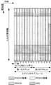
図3は、本実施形態のスロットの構成を示す図である。本実施形態では、OFDMシンボルに対してノーマルCP(normal Cyclic Prefix)が適用される。なお、OFDMシンボルに対して拡張CP(extended Cyclic Prefix)が適用されてもよい。スロットのそれぞれにおいて送信される物理信号または物理チャネルは、リソースグリッドによって表現される。下りリンクにおいて、リソースグリッドは、周波数方向に対する複数のサブキャリアと、時間方向に対する複数のOFDMシンボルによって定義される。上りリンクにおいて、リソースグリッドは、周波数方向に対する複数のサブキャリアと、時間方向に対する複数のSC−FDMAシンボルによって定義される。サブキャリアまたはリソースブロックの数は、セルの帯域幅に依存する。1つのスロットを構成するOFDMシンボルまたはSC−FDMAシンボルの数は、ノーマルCPの場合は7であり、拡張CPの場合は6である。リソースグリッド内のエレメントのそれぞれをリソースエレメントと称する。リソースエレメントは、サブキャリアの番号とOFDMシンボルまたはSC−FDMAシンボルの番号とを用いて識別される。 FIG. 3 is a diagram showing the configuration of the slot according to the present embodiment. In the present embodiment, normal CP (normal cyclic prefix) is applied to the OFDM symbol. Note that an extended CP (extended Cyclic Prefix) may be applied to the OFDM symbol. The physical signal or physical channel transmitted in each of the slots is represented by a resource grid. In the downlink, the resource grid is defined by a plurality of subcarriers in the frequency direction and a plurality of OFDM symbols in the time direction. In the uplink, the resource grid is defined by a plurality of subcarriers in the frequency direction and a plurality of SC-FDMA symbols in the time direction. The number of subcarriers or resource blocks depends on the cell bandwidth. The number of OFDM symbols or SC-FDMA symbols constituting one slot is 7 for the normal CP and 6 for the extended CP. Each element in the resource grid is referred to as a resource element. Resource elements are identified using subcarrier numbers and OFDM symbol or SC-FDMA symbol numbers.
リソースブロックは、ある物理チャネル(PDSCHまたはPUSCHなど)のリソースエレメントにマッピングするために用いられる。リソースブロックは、仮想リソースブロックと物理リソースブロックが定義される。ある物理チャネルは、まず仮想リソースブロックにマップされる。その後、仮想リソースブロックは、物理リソースブロックにマップされる。1つの物理リソースブロックは、時間領域において7個の連続するOFDMシンボルまたはSC−FDMAシンボルと周波数領域において12個の連続するサブキャリアとから定義される。ゆえに、1つの物理リソースブロックは(7×12)個のリソースエレメントから構成される。また、1つの物理リソースブロックは、時間領域において1つのスロットに対応し、周波数領域において180kHzに対応する。物理リソースブロックは周波数領域において0から番号が付けられる。また、同一の物理リソースブロック番号が対応する、1つのサブフレーム内の2つのリソースブロックは、物理リソースブロックペア(PRBペア、RBペア)として定義される。 The resource block is used for mapping to a resource element of a certain physical channel (such as PDSCH or PUSCH). As resource blocks, virtual resource blocks and physical resource blocks are defined. A physical channel is first mapped to a virtual resource block. Thereafter, the virtual resource block is mapped to the physical resource block. One physical resource block is defined by 7 consecutive OFDM symbols or SC-FDMA symbols in the time domain and 12 consecutive subcarriers in the frequency domain. Therefore, one physical resource block is composed of (7 × 12) resource elements. One physical resource block corresponds to one slot in the time domain and corresponds to 180 kHz in the frequency domain. Physical resource blocks are numbered from 0 in the frequency domain. Further, two resource blocks in one subframe corresponding to the same physical resource block number are defined as physical resource block pairs (PRB pair, RB pair).
以下、サブフレームのそれぞれにおいて送信される物理チャネルおよび物理信号について説明する。 Hereinafter, physical channels and physical signals transmitted in each subframe will be described.
図4は、本実施形態の下りリンクサブフレームにおける物理チャネルおよび物理信号の配置の一例を示す図である。基地局装置3は、下りリンクサブフレームにおいて、下りリンク物理チャネル(PBCH、PCFICH、PHICH、PDCCH、EPDCCH、PDSCH)、および/または下りリンク物理信号(同期信号、下りリンク参照信号)を送信できる。なお、PBCHは無線フレーム内のサブフレーム0のみで送信される。なお、下りリンク参照信号は周波数領域および時間領域において分散するリソースエレメントに配置される。説明の簡略化のため、図4において下りリンク参照信号は図示しない。
FIG. 4 is a diagram illustrating an example of the arrangement of physical channels and physical signals in the downlink subframe according to the present embodiment. The
PDCCH領域において、複数のPDCCHが周波数、時間、および/または、空間多重されてもよい。EPDCCH領域において、複数のEPDCCHが周波数、時間、および/または、空間多重されてもよい。PDSCH領域において、複数のPDSCHが周波数、時間、および/または、空間多重されてもよい。PDCCH、PDSCHおよび/またはEPDCCHは周波数、時間、および/または、空間多重されてもよい。 In the PDCCH region, a plurality of PDCCHs may be frequency, time, and / or spatially multiplexed. In the EPDCCH region, a plurality of EPDCCHs may be frequency, time and / or spatially multiplexed. In the PDSCH region, a plurality of PDSCHs may be frequency, time and / or spatially multiplexed. PDCCH, PDSCH and / or EPDCCH may be frequency, time and / or spatially multiplexed.
図5は、本実施形態の上りリンクサブフレームにおける物理チャネルおよび物理信号の配置の一例を示す図である。端末装置1は、上りリンクサブフレームにおいて、上りリンク物理チャネル(PUCCH、PUSCH、PRACH)、および上りリンク物理信号(UL−DMRS、SRS)を送信してもよい。PUCCH領域において、複数のPUCCHが周波数、時間、空間および/またはコード多重される。PUSCH領域において、複数のPUSCHが周波数、時間、空間および/またはコード多重されてもよい。PUCCHおよびPUSCHは周波数、時間、空間および/またはコード多重されてもよい。PRACHは単一のサブフレームまたは2つのサブフレームにわたって配置されてもよい。また、複数のPRACHが符号多重されてもよい。
FIG. 5 is a diagram illustrating an example of an arrangement of physical channels and physical signals in the uplink subframe according to the present embodiment. The
SRSは上りリンクサブフレーム内の最後のSC−FDMAシンボルを用いて送信される。つまり、SRSは上りリンクサブフレーム内の最後のSC−FDMAシンボルに配置される。端末装置1は、単一のセルの単一のSC−FDMAシンボルにおいて、SRSと、PUCCH/PUSCH/PRACHとの同時送信を制限できる。端末装置1は、単一のセルの単一の上りリンクサブフレームにおいて、該上りリンクサブフレーム内の最後のSC−FDMAシンボルを除くSC−FDMAシンボルを用いてPUSCHおよび/またはPUCCHを送信し、該上りリンクサブフレーム内の最後のSC−FDMAシンボルを用いてSRSを送信することができる。つまり、単一のセルの単一の上りリンクサブフレームにおいて、端末装置1は、SRSと、PUSCHおよびPUCCHと、を送信することができる。なお、DMRSはPUCCHまたはPUSCHと時間多重される。説明の簡略化のため、図5においてDMRSは図示しない。
The SRS is transmitted using the last SC-FDMA symbol in the uplink subframe. That is, the SRS is arranged in the last SC-FDMA symbol in the uplink subframe. The
図6は、本実施形態のスペシャルサブフレームにおける物理チャネルおよび物理信号の配置の一例を示す図である。図6において、DwPTSはスペシャルサブフレーム内の1番目から10番目のSC−FDMAシンボルから構成され、GPはスペシャルサブフレーム内の11番目と12番目のSC−FDMAシンボルから構成され、UpPTSはスペシャルサブフレーム内の13番目と14番目のSC−FDMAシンボルから構成される。 FIG. 6 is a diagram illustrating an example of the arrangement of physical channels and physical signals in the special subframe according to the present embodiment. In FIG. 6, DwPTS is composed of the first to tenth SC-FDMA symbols in the special subframe, GP is composed of the eleventh and twelfth SC-FDMA symbols in the special subframe, and UpPTS is the special subframe. It consists of the 13th and 14th SC-FDMA symbols in the frame.
基地局装置3は、スペシャルサブフレームのDwPTSにおいて、PCFICH、PHICH、PDCCH、EPDCCH、PDSCH、同期信号、および、下りリンク参照信号を送信してもよい。基地局装置3は、スペシャルサブフレームのDwPTSにおいて、PBCHの送信を制限できる。端末装置1は、スペシャルサブフレームのUpPTSにおいて、PRACH、およびSRSを送信してもよい。つまり、端末装置1は、スペシャルサブフレームのUpPTSにおいて、PUCCH、PUSCH、およびDMRSの送信を制限できる。
The
図7は、本実施形態の端末装置1の構成を示す概略ブロック図である。図示するように、端末装置1は、上位層処理部101、制御部103、受信部105、送信部107、および送受信アンテナ109を含んで構成される。また、上位層処理部101は、無線リソース制御部1011、サブフレーム設定部1013、スケジューリング情報解釈部1015、および、チャネル状態情報(CSI)報告制御部1017を含んで構成される。また、受信部105は、復号化部1051、復調部1053、多重分離部1055、無線受信部1057、およびチャネル測定部1059を含んで構成される。また、送信部107は、符号化部1071、変調部1073、多重部1075、無線送信部1077、および上りリンク参照信号生成部1079を含んで構成される。
FIG. 7 is a schematic block diagram showing the configuration of the
上位層処理部101は、ユーザの操作等により生成された上りリンクデータ(トランスポートブロック)を、送信部107に出力する。また、上位層処理部101は、媒体アクセス制御(MAC: Medium Access Control)層、パケットデータ統合プロトコル(Packet Data Convergence Protocol: PDCP)層、無線リンク制御(Radio Link Control: RLC)層、無線リソース制御(Radio Resource Control: RRC)層の処理を行なう。上位層処理部101は、キャリアアグリゲーションを行う場合、セルのアクティベーション/デアクティベーションを行うために物理層の制御を行う機能及び上りリンクの送信タイミングを管理するために物理層の制御を行う機能を備えている。上位層処理部101は、受信部105で計算する測定の指示、および、受信部105で計算された測定結果を報告するか否かを判断する機能を備えている。
The upper
上位層処理部101が備える無線リソース制御部1011は、自装置の各種設定情報の管理をする。また、無線リソース制御部1011は、上りリンクの各チャネルに配置される情報を生成し、送信部107に出力する。
The radio
上位層処理部101が備えるサブフレーム設定部1013は、基地局装置3により設定される情報に基づいて、基地局装置3および/または基地局装置3とは異なる基地局装置(例えば、基地局装置3A)におけるサブフレーム設定を管理する。例えば、サブフレーム設定は、サブフレームに対する上りリンクまたは下りリンクの設定である。サブフレーム設定は、サブフレームパターン設定(Subframe pattern configuration)、上りリンク−下りリンク設定(Uplink-downlink configuration)、上りリンク参照UL−DL設定(Uplink reference configuration)、下りリンク参照UL−DL設定(Downlink reference configuration)、および/または、送信方向UL−DL設定(transmission direction configuration)を含む。サブフレーム設定部1013は、サブフレーム設定、サブフレームパターン設定、上りリンク−下りリンク設定、上りリンク参照UL−DL設定、下りリンク参照UL−DL設定、および/または、送信方向UL−DL設定をセットする。また、サブフレーム設定部1013は、少なくとも2つのサブフレームセットをセットできる。なお、サブフレームパターン設定は、EPDCCHサブフレーム設定を含む。なお、サブフレーム設定部1013は、端末サブフレーム設定部とも呼称される。
The
上位層処理部101が備えるスケジューリング情報解釈部1015は、受信部105を介して受信したDCIフォーマット(スケジューリング情報)の解釈をし、前記DCIフォーマットを解釈した結果に基づいて、受信部105および送信部107の制御を行なうために制御情報を生成し、制御部103に出力する。
The scheduling
スケジューリング情報解釈部1015は、サブフレーム設定、サブフレームパターン設定、上りリンク−下りリンク設定、上りリンク参照UL−DL設定、下りリンク参照UL−DL設定、および/または、送信方向UL−DL設定に基づいて、送信処理および受信処理を行うタイミングを決定する。
The scheduling
CSI報告制御部1017は、CSI参照リソースを特定する。CSI報告制御部1017は、チャネル測定部1059に、CSI参照リソースに関連するCQIを導き出すよう指示する。CSI報告制御部1017は、送信部107に、CQIを送信するよう指示をする。CSI報告制御部1017は、チャネル測定部1059がCQIを算出する際に用いる設定をセットする。
The CSI
制御部103は、上位層処理部101からの制御情報に基づいて、受信部105および送信部107の制御を行なう制御信号を生成する。制御部103は、生成した制御信号を受信部105および送信部107に出力して、受信部105および送信部107の制御を行なう。
The
受信部105は、制御部103から入力された制御信号に基づいて、送受信アンテナ109が基地局装置3から受信した受信信号を、分離、復調、復号する。受信部105は、復号した情報を上位層処理部101に出力する。
The receiving
無線受信部1057は、送受信アンテナ109が受信した下りリンクの信号を、中間周波数に変換し(ダウンコンバート: down convert)、不要な周波数成分を除去し、信号レベルが適切に維持されるように増幅レベルを制御し、受信した信号の同相成分および直交成分に基づいて、直交復調し、直交復調されたアナログ信号をディジタル信号に変換する。無線受信部1057は、変換したディジタル信号からガードインターバル(Guard Interval: GI)に相当する部分を除去し、ガードインターバルを除去した信号に対して高速フーリエ変換(Fast Fourier Transform: FFT)を行ない、周波数領域の信号を抽出する。
The radio reception unit 1057 converts a downlink signal received by the transmission /
多重分離部1055は、抽出した信号から、PHICH、PDCCH、EPDCCH、PDSCH、および/または下りリンク参照信号を、それぞれ分離する。また、多重分離部1055は、チャネル測定部1059から入力された伝搬路の推定値から、PHICH、PDCCH、EPDCCH、および/またはPDSCHの伝搬路の補償を行なう。また、多重分離部1055は、分離した下りリンク参照信号をチャネル測定部1059に出力する。
The
復調部1053は、PHICHに対して対応する符号を乗算して合成し、合成した信号に対してBPSK(Binary Phase Shift Keying)変調方式の復調を行ない、復号化部1051へ出力する。復号化部1051は、自装置宛てのPHICHを復号し、復号したHARQインディケータを上位層処理部101に出力する。復調部1053は、PDCCHおよび/またはEPDCCHに対して、QPSK変調方式の復調を行ない、復号化部1051へ出力する。復号化部1051は、PDCCHおよび/またはEPDCCHの復号を試み、復号に成功した場合、復号した下りリンク制御情報と下りリンク制御情報が対応するRNTIとを上位層処理部101に出力する。
復調部1053は、PDSCHに対して、QPSK(Quadrature Phase Shift Keying)、16QAM(Quadrature Amplitude Modulation)、64QAM等の下りリンクグラントで通知された変調方式の復調を行ない、復号化部1051へ出力する。復号化部1051は、下りリンク制御情報で通知された符号化率に関する情報に基づいて復号を行ない、復号した下りリンクデータ(トランスポートブロック)を上位層処理部101へ出力する。
チャネル測定部1059は、多重分離部1055から入力された下りリンク参照信号から下りリンクのパスロスやチャネルの状態を測定し、測定したパスロスやチャネルの状態を上位層処理部101へ出力する。また、チャネル測定部1059は、下りリンク参照信号から下りリンクの伝搬路の推定値を算出し、多重分離部1055へ出力する。チャネル測定部1059は、CQIの算出のために、チャネル測定、および/または、干渉測定を行なう。チャネル測定部1059は、多重分離部1055から入力された下りリンク参照信号から上位層へ通知する測定を行う。チャネル測定部1059は、RSRPおよびRSRQの計算を行い、上位層処理部101へ出力する。
送信部107は、制御部103から入力された制御信号に従って、上りリンク参照信号を生成し、上位層処理部101から入力された上りリンクデータ(トランスポートブロック)を符号化および変調し、PUCCH、PUSCH、および生成した上りリンク参照信号を多重し、送受信アンテナ109を介して基地局装置3に送信する。
The
符号化部1071は、上位層処理部101から入力された上りリンク制御情報を畳込み符号化、ブロック符号化等の符号化を行なう。また、符号化部1071は、PUSCHのスケジューリングに用いられる情報に基づいてターボ符号化を行なう。
The
変調部1073は、符号化部1071から入力された符号化ビットをBPSK、QPSK、16QAM、64QAM等の下りリンク制御情報で通知された変調方式または、チャネル毎に予め定められた変調方式で変調する。変調部1073は、PUSCHのスケジューリングに用いられる情報に基づき、空間多重されるデータの系列の数を決定し、MIMO SM(Multiple Input Multiple Output Spatial Multiplexing)を用いることにより同一のPUSCHで送信される複数の上りリンクデータを、複数の系列にマッピングし、この系列に対してプレコーディング(precoding)を行なう。
The
上りリンク参照信号生成部1079は、基地局装置3を識別するための物理層セル識別子(physical cell identity: PCI、Cell IDなどと称する。)、上りリンク参照信号を配置する帯域幅、上りリンクグラントで通知されたサイクリックシフト、DMRSシーケンスの生成に対するパラメータの値などを基に、予め定められた規則(式)で求まる系列を生成する。多重部1075は、制御部103から入力された制御信号に従って、PUSCHの変調シンボルを並列に並び替えてから離散フーリエ変換(Discrete Fourier Transform: DFT)する。また、多重部1075は、PUCCHとPUSCHの信号と生成した上りリンク参照信号を送信アンテナポート毎に多重する。つまり、多重部1075は、PUCCHとPUSCHの信号と生成した上りリンク参照信号を送信アンテナポート毎にリソースエレメントに配置する。
The uplink reference
無線送信部1077は、多重された信号を逆高速フーリエ変換(Inverse Fast Fourier Transform: IFFT)して、SC−FDMA方式の変調を行い、SC−FDMA変調されたSC−FDMAシンボルにガードインターバルを付加し、ベースバンドのディジタル信号を生成し、ベースバンドのディジタル信号をアナログ信号に変換し、アナログ信号から中間周波数の同相成分および直交成分を生成し、中間周波数帯域に対する余分な周波数成分を除去し、中間周波数の信号を高周波数の信号に変換(アップコンバート: up convert)し、余分な周波数成分を除去し、電力増幅し、送受信アンテナ109に出力して送信する。
図8は、本実施形態の基地局装置3の構成を示す概略ブロック図である。図示するように、基地局装置3は、上位層処理部301、制御部303、受信部305、送信部307、および、送受信アンテナ309、を含んで構成される。また、上位層処理部301は、無線リソース制御部3011、サブフレーム設定部3013、スケジューリング部3015、および、CSI報告制御部3017を含んで構成される。また、受信部305は、復号化部3051、復調部3053、多重分離部3055、無線受信部3057とチャネル測定部3059を含んで構成される。また、送信部307は、符号化部3071、変調部3073、多重部3075、無線送信部3077、および、下りリンク参照信号生成部3079を含んで構成される。
FIG. 8 is a schematic block diagram illustrating the configuration of the
上位層処理部301は、媒体アクセス制御(MAC: Medium Access Control)層、パケットデータ統合プロトコル(Packet Data Convergence Protocol: PDCP)層、無線リンク制御(Radio Link Control: RLC)層、無線リソース制御(Radio Resource Control: RRC)層の処理を行なう。また、上位層処理部301は、受信部305、および送信部307の制御を行なうために制御情報を生成し、制御部303に出力する。また、上位層処理部301は、報告された測定結果を取得する機能を備えている。
The upper
上位層処理部301が備える無線リソース制御部3011は、下りリンクのPDSCHに配置される下りリンクデータ(トランスポートブロック)、システムインフォメーション、RRCメッセージ、MAC CE(Control Element)などを生成し、又は上位ノードから取得し、送信部307に出力する。また、無線リソース制御部3011は、端末装置1各々の各種設定情報の管理をする。
The radio
上位層処理部301が備えるサブフレーム設定部3013は、サブフレーム設定、サブフレームパターン設定、上りリンク−下りリンク設定、上りリンク参照UL−DL設定、下りリンク参照UL−DL設定、および/または、送信方向UL−DL設定の管理を、端末装置1のそれぞれに対して行なう。サブフレーム設定部3013は、端末装置1のそれぞれに対して、サブフレーム設定、サブフレームパターン設定、上りリンク−下りリンク設定、上りリンク参照UL−DL設定、下りリンク参照UL−DL設定、および/または、送信方向UL−DL設定をセットする。サブフレーム設定部3013は、サブフレーム設定に関する情報を端末装置1に送信する。なお、サブフレーム設定部3013は、基地局サブフレーム設定部とも呼称される。
The
基地局装置3は、端末装置1に対する、サブフレーム設定、サブフレームパターン設定、上りリンク−下りリンク設定、上りリンク参照UL−DL設定、下りリンク参照UL−DL設定、および/または、送信方向UL−DL設定を決定してもよい。また、基地局装置3は、端末装置1に対する、サブフレーム設定、サブフレームパターン設定、上りリンク−下りリンク設定、上りリンク参照UL−DL設定、下りリンク参照UL−DL設定、および/または、送信方向UL−DL設定を上位ノードから指示されてもよい。
The
例えば、サブフレーム設定部3013は、上りリンクのトラフィック量および下りリンクのトラフィック量に基づいて、サブフレーム設定、サブフレームパターン設定、上りリンク−下りリンク設定、上りリンク参照UL−DL設定、下りリンク参照UL−DL設定、および/または、送信方向UL−DL設定を決定してもよい。
For example, the
サブフレーム設定部3013は、少なくとも2つのサブフレームセットの管理を行なうことができる。サブフレーム設定部3013は、端末装置1のそれぞれに対して、少なくとも2つのサブフレームセットをセットしてもよい。サブフレーム設定部3013は、サービングセルのそれぞれに対して、少なくとも2つのサブフレームセットをセットしてもよい。サブフレーム設定部3013は、CSIプロセスのそれぞれに対して、少なくとも2つのサブフレームセットをセットしてもよい。サブフレーム設定部3013は、少なくとも2つのサブフレームセットを示す情報を、送信部307を介して、端末装置1に送信できる。
The
上位層処理部301が備えるスケジューリング部3015は、受信したチャネル状態情報およびチャネル測定部3059から入力された伝搬路の推定値やチャネルの品質などから、物理チャネル(PDSCHおよびPUSCH)を割り当てる周波数およびサブフレーム、物理チャネル(PDSCHおよびPUSCH)の符号化率および変調方式および送信電力などを決定する。スケジューリング部3015は、フレキシブルサブフレームにおいて下りリンク物理チャネルおよび/または下りリンク物理信号をスケジュールするか、上りリンク物理チャネルおよび/または上りリンク物理信号をスケジュールするかを決定する。スケジューリング部3015は、スケジューリング結果に基づき、受信部305、および送信部307の制御を行なうために制御情報(例えば、DCIフォーマット)を生成し、制御部303に出力する。
The
スケジューリング部3015は、スケジューリング結果に基づき、物理チャネル(PDSCHおよびPUSCH)のスケジューリングに用いられる情報を生成する。スケジューリング部3015は、UL−DL設定、サブフレームパターン設定、上りリンク−下りリンク設定、上りリンク参照UL−DL設定、下りリンク参照UL−DL設定、および/または、送信方向UL−DL設定に基づいて、送信処理および受信処理を行うタイミング(サブフレーム)を決定する。
The
上位層処理部301が備えるCSI報告制御部3017は、端末装置1のCSI報告を制御する。CSI報告制御部3017は、端末装置1がCSI参照リソースにおいてCQIを導き出すために想定する、各種設定を示す情報を、送信部307を介して、端末装置1に送信する。
A CSI
制御部303は、上位層処理部301からの制御情報に基づいて、受信部305、および送信部307の制御を行なう制御信号を生成する。制御部303は、生成した制御信号を受信部305、および送信部307に出力して受信部305、および送信部307の制御を行なう。
The
受信部305は、制御部303から入力された制御信号に従って、送受信アンテナ309を介して端末装置1から受信した受信信号を分離、復調、復号し、復号した情報を上位層処理部301に出力する。無線受信部3057は、送受信アンテナ309を介して受信された上りリンクの信号を、中間周波数に変換し(ダウンコンバート: down convert)、不要な周波数成分を除去し、信号レベルが適切に維持されるように増幅レベルを制御し、受信された信号の同相成分および直交成分に基づいて、直交復調し、直交復調されたアナログ信号をディジタル信号に変換する。
The receiving
無線受信部3057は、変換したディジタル信号からガードインターバル(Guard Interval: GI)に相当する部分を除去する。無線受信部3057は、ガードインターバルを除去した信号に対して高速フーリエ変換(Fast Fourier Transform: FFT)を行い、周波数領域の信号を抽出し多重分離部3055に出力する。
The
多重分離部1055は、無線受信部3057から入力された信号をPUCCH、PUSCH、上りリンク参照信号などの信号に分離する。なお、この分離は、予め基地局装置3が無線リソース制御部3011で決定し、各端末装置1に通知した上りリンクグラントに含まれる無線リソースの割り当て情報に基づいて行なわれる。また、多重分離部3055は、チャネル測定部3059から入力された伝搬路の推定値から、PUCCHとPUSCHの伝搬路の補償を行なう。また、多重分離部3055は、分離した上りリンク参照信号をチャネル測定部3059に出力する。
The
復調部3053は、PUSCHを逆離散フーリエ変換(Inverse Discrete Fourier Transform: IDFT)し、変調シンボルを取得し、PUCCHとPUSCHの変調シンボルそれぞれに対して、BPSK(Binary Phase Shift Keying)、QPSK、16QAM、64QAM等の予め定められた、または自装置が端末装置1各々に上りリンクグラントで予め通知した変調方式を用いて受信信号の復調を行なう。復調部3053は、端末装置1各々に上りリンクグラントで予め通知した空間多重される系列の数と、この系列に対して行なうプリコーディングを指示する情報に基づいて、MIMO SMを用いることにより同一のPUSCHで送信された複数の上りリンクデータの変調シンボルを分離する。
The
復号化部3051は、復調されたPUCCHとPUSCHの符号化ビットを、予め定められた符号化方式の、予め定められた、又は自装置が端末装置1に上りリンクグラントで予め通知した符号化率で復号を行ない、復号した上りリンクデータと、上りリンク制御情報を上位層処理部101へ出力する。PUSCHが再送信の場合は、復号化部3051は、上位層処理部301から入力されるHARQバッファに保持している符号化ビットと、復調された符号化ビットを用いて復号を行なう。チャネル測定部309は、多重分離部3055から入力された上りリンク参照信号から伝搬路の推定値、チャネルの品質などを測定し、多重分離部3055および上位層処理部301に出力する。
The
送信部307は、制御部303から入力された制御信号に従って、下りリンク参照信号を生成し、上位層処理部301から入力されたHARQインディケータ、下りリンク制御情報、下りリンクデータを符号化、および変調し、PHICH、PDCCH、EPDCCH、PDSCH、および下りリンク参照信号を多重して、送受信アンテナ309を介して端末装置1に信号を送信する。
The
符号化部3071は、上位層処理部301から入力されたHARQインディケータ、下りリンク制御情報、および下りリンクデータを、ブロック符号化、畳込み符号化、ターボ符号化等の予め定められた符号化方式を用いて符号化を行なう、または無線リソース制御部3011が決定した符号化方式を用いて符号化を行なう。変調部3073は、符号化部3071から入力された符号化ビットをBPSK、QPSK、16QAM、64QAM等の予め定められた、または無線リソース制御部3011が決定した変調方式で変調する。
The
下りリンク参照信号生成部3079は、基地局装置3を識別するための物理レイヤセル識別子(PCI)などを基に予め定められた規則で求まる、端末装置1が既知の系列を下りリンク参照信号として生成する。多重部3075は、変調された各チャネルの変調シンボルと生成された下りリンク参照信号を多重する。つまり、多重部3075は、変調された各チャネルの変調シンボルと生成された下りリンク参照信号をリソースエレメントに配置する。
The downlink reference
無線送信部3077は、多重された変調シンボルなどを逆高速フーリエ変換(Inverse Fast Fourier Transform: IFFT)して、OFDM方式の変調を行い、OFDM変調されたOFDMシンボルにガードインターバルを付加し、ベースバンドのディジタル信号を生成し、ベースバンドのディジタル信号をアナログ信号に変換し、アナログ信号から中間周波数の同相成分および直交成分を生成し、中間周波数帯域に対する余分な周波数成分を除去し、中間周波数の信号を高周波数の信号に変換(アップコンバート: up convert)し、余分な周波数成分を除去し、電力増幅し、送受信アンテナ309に出力して送信する。
The
ここで、PDCCHまたはEPDCCHは、下りリンク制御情報(DCI)を端末装置へ通知(指定)するために使用される。例えば、下りリンク制御情報には、PDSCHのリソース割り当てに関する情報、MCS(Modulation and Coding scheme)に関する情報、スクランブリングアイデンティティ(スクランブリング識別子とも呼称される)に関する情報、参照信号系列アイデンティティ(ベースシーケンスアイデンティティ、ベースシーケンス識別子、ベースシーケンスインデックスとも呼称される)に関する情報などが含まれる。 Here, PDCCH or EPDCCH is used for notifying (designating) downlink control information (DCI) to the terminal apparatus. For example, the downlink control information includes information related to PDSCH resource allocation, information related to MCS (Modulation and Coding scheme), information related to scrambling identity (also referred to as scrambling identifier), reference signal sequence identity (base sequence identity, Information on a base sequence identifier and a base sequence index).
以下では、小セルについて説明する。 Below, a small cell is demonstrated.
小セルとは、マクロセルに比べて低送信電力の基地局装置3によって構成される、カバレッジが小さなセルの総称である。小セルは、カバレッジが小さく設定することが可能となるため、密に配置して運用することができる。小セルの基地局装置3は、マクロセルの基地局装置と異なる場所に配置される。密に配置される小セル同士は同期され、小セルクラスター(Small cell Cluster)として構成することができる。小セルクラスター内の小セル間は、バックホール(光ファイバー、X2インターフェース、S1インターフェース)で接続され、小セルクラスター内の小セルでは、eICIC(enhanced Inter-Cell Interference Coordination)、FeICIC(Further enhanced Inter-Cell Interference Coordination)、CoMP(Coordinated Multi-Point transmission/reception)などの干渉抑制技術を適用することができる。小セルはマクロセルと異周波数帯で運用されてもよいし、同周波数帯で運用されてもよい。特に、伝搬路減衰(パスロス)の観点から、小セルをマクロセルに比べて高周波数帯で運用することで、より小カバレッジで構成することが容易である。
A small cell is a generic term for a cell having a small coverage and configured by the
異周波数帯で運用される小セルは、マクロセルとキャリアアグリゲーション技術またはデュアルコネクティビティ技術を用いて運用される。 A small cell operated in a different frequency band is operated using a macro cell and a carrier aggregation technology or a dual connectivity technology.
また、小セルは、マクロセルと同一周波数で運用されてもよい。小セルは、マクロセルのカバレッジ外で運用されてもよい。また、小セルの基地局装置3は、マクロセルの基地局装置と同一の場所に配置されてもよい。
The small cell may be operated at the same frequency as the macro cell. Small cells may be operated outside the coverage of macro cells. The small cell
また、あるセルがマクロセルか小セルかは、基地局装置3で認識するものであり、端末装置1が認識する必要はない。例えば、基地局装置3は端末装置1に対して、マクロセルをPcellとして設定し、小セルをScellまたはpSCellとして設定することができる。いずれの場合においても、端末装置1はPCell、SCellまたはpSCellとして認識するだけでよく、マクロセルまたは小セルとして認識する必要はない。
Whether a certain cell is a macro cell or a small cell is recognized by the
以下では、キャリアアグリゲーション技術およびデュアルコネクティビティ技術の詳細について説明する。 Hereinafter, details of the carrier aggregation technology and the dual connectivity technology will be described.
端末装置1の能力(性能、機能)に依存して、セカンダリーセルはプライマリーセルと一緒にサービングセルのセットを構成して設定される。端末装置1に設定される下りリンクのコンポーネントキャリアの数は端末装置1に設定される上りリンクコンポーネントキャリアの数よりも多いか同じでなければならず、上りリンクコンポーネントキャリアのみをセカンダリーセルとして設定することはできない。
Depending on the capability (performance, function) of the
端末装置1は、PUCCHの送信に常にプライマリーセルおよびプライマリーセカンダリーセルを用いる。言い換えると、端末装置1は、プライマリーセルおよびプライマリーセカンダリーセル以外のセカンダリーセルで、PUCCHを送信することを期待しない。
The
セカンダリーセルの再設定/追加/削除はRRCによって行われる。新しいセカンダリーセルを追加するとき、専用RRCシグナリングによって新しいセカンダリーセルが必要とされる全てのシステム情報を送信する。すなわち、RRCコネクテッドモードにおいては、報知によってシステム情報をセカンダリーセルから直接得る必要はない。 Secondary cell reconfiguration / addition / deletion is performed by RRC. When adding a new secondary cell, it sends all system information needed for the new secondary cell by dedicated RRC signaling. That is, in the RRC connected mode, it is not necessary to obtain system information directly from the secondary cell by notification.
キャリアアグリゲーションが設定されたとき、セカンダリーセルのアクティベーション/デアクティベーションの仕組みがサポートされる。プライマリーセルはアクティベーション/デアクティベーションは適用されない。セカンダリーセルがデアクティベーションされたとき、端末装置1は関連するPDCCHまたはPDSCHを受信する必要がなく、関連する上りリンクで送信できず、そしてCQI測定を行なう必要がない。反対に、セカンダリーセルがアクティベーションされたとき、端末装置1はPDSCHとPDCCHを受信するため、CQI測定を行なうことができると期待する。
When the carrier aggregation is set, the activation / deactivation mechanism of the secondary cell is supported. Primary cells are not activated / deactivated. When the secondary cell is deactivated, the
アクティベーション/デアクティベーションの仕組みはMAC CEとデアクティベーションタイマーの組み合わせに基づく。MAC CEはセカンダリーセルのアクティベーションとデアクティベーションの情報をビットマップで通知する。1がセットされたビットは、関連するセカンダリーセルのアクティベーションを示し、0がセットされたビットは、関連するセカンダリーセルのデアクティベーションを示す。 The activation / deactivation mechanism is based on a combination of MAC CE and deactivation timer. The MAC CE notifies the activation and deactivation information of the secondary cell with a bitmap. Bits that are set to 1 indicate activation of the associated secondary cell, and bits that are set to 0 indicate deactivation of the associated secondary cell.
なお、端末装置1に設定されたセカンダリーセルは、初期状態としてデアクティベーションが設定されている。つまり、端末装置1に対して、セカンダリーセルに対する種々のパラメータが設定されたとしても、すぐにそのセカンダリーセルを用いて通信が行なえるとは限らない。
The secondary cell set in the
次に、MAC CEの一例について説明する。 Next, an example of the MAC CE will be described.
アクティベーション/デアクティベーションMAC CEの構成の一例を説明する。MAC CEは、固定サイズであって、7つのCiフィールドと1つのRフィールドで構成されていて、次のように定義される。Ciは、セカンダリーセルインデックス(SCellIndex)iに設定されたセカンダリーセルがある場合、Ciフィールドはセカンダリーセルインデックスiを伴うセカンダリーセルのアクティベーション/デアクティベーションの状態を示す。セカンダリーセルインデックスiが設定されたセカンダリーセルがない場合、端末装置1はCiフィールドを無視する。Ciフィールドが“1”にセットされている場合、セカンダリーセルインデックスiを伴うセカンダリーセルがアクティベートされることを示す。Ciフィールドが“0”にセットされている場合、セカンダリーセルインデックスiを伴うセカンダリーセルがデアクティベートされていることを示す。また、Rは、リザーブされたビットであり、“0”にセットされている。
An example of the configuration of the activation / deactivation MAC CE will be described. The MAC CE has a fixed size and is composed of seven Ci fields and one R field, and is defined as follows. When Ci is a secondary cell set to secondary cell index (SCellIndex) i, the Ci field indicates the activation / deactivation state of the secondary cell with secondary cell index i. When there is no secondary cell in which the secondary cell index i is set, the
次に、セカンダリーセルに対するデアクティベーションタイマー(DeactivationTimer)の一例について説明する。 Next, an example of a deactivation timer (DeactivationTimer) for the secondary cell will be described.
デアクティベーションタイマーがセカンダリーセルに対して設定される場合、セカンダリーセルの維持時間に関連するタイマーである。端末装置1は、セカンダリーセル毎にデアクティベーションタイマーを保持し、デアクティベーションタイマーが満了すると、満了したデアクティベーションタイマーに関連するセカンダリーセルをデアクティベーションする。
When the deactivation timer is set for the secondary cell, it is a timer related to the maintenance time of the secondary cell. The
セカンダリーセルに対するデアクティベーションタイマーの初期値は、上位層(RRC層)からパラメータsCellDeactivationTimer−r10を用いて設定される。セカンダリーセルに対するデアクティベーションタイマーの初期値は、例えば、無線フレームの数に関連する値であるrf2、rf4、rf8、rf16、rf32、rf64、rf128の内から1つが設定される。ここで、rf2は、2無線フレームに対応し、rf4は、4無線フレームに対応し、rf8は、8無線フレームに対応し、rf16は、16無線フレームに対応し、rf32は、32無線フレームに対応し、rf64は、64無線フレームに対応し、rf128は、128無線フレームに対応する。 The initial value of the deactivation timer for the secondary cell is set from the upper layer (RRC layer) using the parameter sCellDeactivationTimer-r10. As the initial value of the deactivation timer for the secondary cell, for example, one of rf2, rf4, rf8, rf16, rf32, rf64, and rf128, which is a value related to the number of radio frames, is set. Here, rf2 corresponds to 2 radio frames, rf4 corresponds to 4 radio frames, rf8 corresponds to 8 radio frames, rf16 corresponds to 16 radio frames, and rf32 corresponds to 32 radio frames. Correspondingly, rf64 corresponds to 64 radio frames and rf128 corresponds to 128 radio frames.
なお、セカンダリーセルに対するデアクティベーションタイマーに関連するフィールド(パラメータsCellDeactivationTimer-r10)は、1つ以上のセカンダリーセルが設定された端末装置1のみに設定される。
The field related to the deactivation timer for the secondary cell (parameter sCellDeactivationTimer-r10) is set only in the
なお、デアクティベーションタイマーに関連するフィールドが存在しない場合、端末装置1は、デアクティベーションタイマーに関連するフィールドの既存の値を削除し、値として無限大(infinity)が設定されていると仮定する。
When there is no field related to the deactivation timer, the
なお、端末装置1に対して、セカンダリーセルに対するデアクティベーションタイマーに関連するフィールドが1つだけ設定される場合には、各セカンダリーセルに同じデアクティベーションタイマーの初期値が適応される(デアクティベーションタイマーに関連する機能は各セカンダリーセルで独立に実行される)。
When only one field related to the deactivation timer for the secondary cell is set for the
アクティベーション/デアクティベーションの仕組みの一例について説明する。 An example of the activation / deactivation mechanism will be described.
セカンダリーセルのアクティベーションを指示するMAC CEを受信した場合、端末装置1は、MAC CEによってアクティベーションが設定されたセカンダリーセルをアクティベーションとして設定する。ここで、端末装置1は、MAC CEによってアクティベーションが設定されたセカンダリーセルに対して、以下のオペレーションを行なうことができる。そのオペレーションは、セカンダリーセルでのSRSの送信、セカンダリーセルに対するCQI(Channel Quality Indicator)/PMI(Precoding Matrix Indicator)/RI(Rank Indicator)/PTI(Precoding Type Indicator)の報告、セカンダリーセルでの上りリンクデータ(UL-SCH)の送信、セカンダリーセルでのRACHの送信、セカンダリーセルでのPDCCHのモニタ、セカンダリーセルに対するPDCCHのモニタである。
When receiving the MAC CE instructing the activation of the secondary cell, the
セカンダリーセルのアクティベーションを指示するMAC CEを受信した場合、端末装置1は、MAC CEによってアクティベーションが設定されたセカンダリーセルに関連するデアクティベーションタイマーをスタートまたはリスタートする。なお、スタートとは、値を保持してタイマーのカウントが開始することである。なお、リスタートとは、値を初期値に設定してタイマーのカウントが開始することである。
When receiving the MAC CE instructing the activation of the secondary cell, the
セカンダリーセルのアクティベーションを指示するMAC CEを受信した場合、端末装置1は、送信電力余力(パワーヘッドルーム(PHR: Power head room))の送信をトリガする。
When receiving the MAC CE instructing the activation of the secondary cell, the
セカンダリーセルのデアクティベーションを指示するMAC CEを受信した場合、もしくは、セカンダリーセルに関連付けられているデアクティベーションタイマーが満了した場合、端末装置1は、MAC CEによってデアクティベーションが設定されたセカンダリーセルをデアクティベーションとして設定する。
When the MAC CE instructing the deactivation of the secondary cell is received or when the deactivation timer associated with the secondary cell expires, the
セカンダリーセルのデアクティベーションを指示するMAC CEを受信した場合、もしくは、セカンダリーセルに関連付けられているデアクティベーションタイマーが満了した場合、端末装置1は、MAC CEによってデアクティベーションが設定されたセカンダリーセルに関連するデアクティベーションタイマーをストップする。
When the MAC CE instructing the deactivation of the secondary cell is received or when the deactivation timer associated with the secondary cell expires, the
セカンダリーセルのデアクティベーションを指示するMAC CEを受信した場合、もしくは、セカンダリーセルに関連付けられているデアクティベーションタイマーが満了した場合、端末装置1は、MAC CEによってデアクティベーションが設定されたセカンダリーセルに関連する全てのHARQバッファをフラッシュする。
When the MAC CE instructing the deactivation of the secondary cell is received or when the deactivation timer associated with the secondary cell expires, the
アクティベーションされたセカンダリーセルにおけるPDCCHが、下りリンクグラント(downlink grant)または上りリンクグラント(uplink grant)を示す場合、もしくは、アクティベーションされたセカンダリーセルをスケジューリングするサービングセルにおけるPDCCHが、アクティベーションされたセカンダリーセルに対する下りリンクグラント(downlink grant)またはアクティベーションされたセカンダリーセルに対する上りリンクグラント(uplink grant)を示す場合、端末装置1は、アクティベーションされたセカンダリーセルに関連するデアクティベーションタイマーをリスタートする。
When the activated PDCCH in the secondary cell indicates a downlink grant or an uplink grant, or the PDCCH in the serving cell that schedules the activated secondary cell is activated When indicating a downlink grant for a cell or an uplink grant for an activated secondary cell, the
セカンダリーセルがデアクティベートされた場合、端末装置1は、デアクティベートされたセカンダリーセルに対して、以下のオペレーションを行なわない。そのオペレーションは、セカンダリーセルでSRSの送信、セカンダリーセルに対するCQI/PMI/RI/PTIの報告、セカンダリーセルで上りリンクデータ(UL-SCH)の送信、セカンダリーセルでRACHの送信、セカンダリーセルでPDCCHのモニタ、セカンダリーセルに対するPDCCHのモニタである。
When the secondary cell is deactivated, the
ランダムアクセスプロシージャ(Random Access procedure)を実行中のセカンダリーセルに対してデアクティベーションが設定された場合、端末装置1は、実行中のランダムアクセスプロシージャを中止する。
When the deactivation is set for the secondary cell that is executing the random access procedure, the
セカンダリーセルアクティベーション/デアクティベーションのタイミングの一例について説明する。なお、説明のため、ここで説明するセカンダリーセルアクティベーション/デアクティベーションのタイミングの一例は、第1のセカンダリーセルアクティベーション/デアクティベーションのタイミング、または、従来のセカンダリーセルアクティベーション/デアクティベーションのタイミングと称する。 An example of the timing of secondary cell activation / deactivation will be described. For the sake of explanation, an example of the secondary cell activation / deactivation timing described here is the first secondary cell activation / deactivation timing or the conventional secondary cell activation / deactivation timing. Called.
端末装置1は、サブフレームnにおいて、セカンダリーセルのためのアクティベーションコマンド(例えば、セカンダリーセルのアクティベーションを指示するMAC CE)を受信したとき、上述したアクティベートに対応する動作のうち、CSIレポーティングに関係する動作と該セカンダリーセルに関連付けられているデアクティベーションタイマー(sCellDeactivationTimer)に関係する動作を除く動作が、定義されている最小要件(minimum requirement、例えば24ms(24サブフレーム)、34ms(34サブフレーム))よりも遅くなく、かつ、サブフレームn+8より早くなく適用されなければならない。また、上述したアクティベートに対応する動作のうち、CSIレポーティングに関係する動作と該セカンダリーセルに関連付けられているデアクティベーションタイマー(sCellDeactivationTimer)に関係する動作は、サブフレームn+8において適用されなければならない。
When receiving an activation command for the secondary cell (for example, MAC CE instructing activation of the secondary cell) in the subframe n, the
すなわち、端末装置1は、サブフレームnにおいて、セカンダリーセルのためのアクティベーションコマンドを受信したとき、サブフレームn+8において、セカンダリーセルに対するCQI(Channel Quality Indicator)/PMI(Precoding Matrix Indicator)/RI(Rank Indicator)/PTI(Precoding Type Indicator)の報告、アクティベーションコマンドによってアクティベーションが設定されたセカンダリーセルに関連するデアクティベーションタイマーをスタートまたはリスタートを適用しなければならない。そして、最小要件(minimum requirement、例えば24ms(24サブフレーム)、34ms(34サブフレーム))よりも遅くなく、かつ、サブフレームn+8より早くなく、セカンダリーセルでのSRSの送信、セカンダリーセルでの上りリンクデータ(UL-SCH)の送信、セカンダリーセルでのRACHの送信、セカンダリーセルでのPDCCHのモニタ、セカンダリーセルに対するPDCCHのモニタを行うことができる。すなわち、最小要件(minimum requirement、例えば24ms(24サブフレーム)、34ms(34サブフレーム))よりも遅く、かつ、サブフレームn+8より早く、セカンダリーセルでのSRSの送信、セカンダリーセルでの上りリンクデータ(UL-SCH)の送信、セカンダリーセルでのRACHの送信、セカンダリーセルでのPDCCHのモニタ、セカンダリーセルに対するPDCCHのモニタを行うことはできない。
That is, when receiving an activation command for the secondary cell in subframe n,
なお、デアクティベーションタイマーのスタートとは、値を保持してタイマーのカウントが開始することである。なお、デアクティベーションタイマーのリスタートとは、値を初期値に設定してタイマーのカウントが開始することである。 The start of the deactivation timer means that the value is held and the timer starts counting. The deactivation timer is restarted when the value is set to an initial value and the timer starts counting.
なお、最小要件(minimum requirement)は、FDD(E−UTRA FDD)とTDD(E−UTRA TDD)で異なる値であってもよい。すなわち、セカンダリーセルのためのアクティベーションコマンドを受信した端末装置1は、該セカンダリーセルがFDDであるかTDDであるかによって異なる最小要件(minimum requirement)を適用(設定)してもよい。
The minimum requirement may be a different value between FDD (E-UTRA FDD) and TDD (E-UTRA TDD). That is, the
端末装置1は、サブフレームnにおいて、セカンダリーセルのためのデアクティベーションコマンド(セカンダリーセルのデアクティベーションを指示するMAC CE)を受信したとき、または、該セカンダリーセルに関連するデアクティベーションタイマー(sCellDeactivationTimer)が満了したとき、上述したデアクティベートに対応する動作のうち、CSIレポーティングに関係する動作を除く動作が、定義されている最小要件(minimum requirement、例えば24ms(24サブフレーム)、34ms(34サブフレーム))よりも遅くなく、かつ、サブフレームn+8より早くなく適用されなければならない。また、上述したデアクティベートに対応する動作のうち、CSIレポーティングに関係する動作は、サブフレームn+8において適用されなければならない。すなわち、定義されている最小要件(minimum requirement、例えば24ms(24サブフレーム)、34ms(34サブフレーム))よりも遅く、かつ、サブフレームn+8より早く適用されない。
In the subframe n, the
すなわち、端末装置1は、サブフレームnにおいて、セカンダリーセルのためのデアクティベーションコマンド(セカンダリーセルのデアクティベーションを指示するMAC CE)を受信したとき、サブフレームn+8において、セカンダリーセルに対するCQI(Channel Quality Indicator)/PMI(Precoding Matrix Indicator)/RI(Rank Indicator)/PTI(Precoding Type Indicator)の報告を行わない。そして、最小要件(minimum requirement、例えば24ms(24サブフレーム)、34ms(34サブフレーム))よりも遅くなく、かつ、サブフレームn+8より早くなく、セカンダリーセルでのSRSの送信を行わず、セカンダリーセルでの上りリンクデータ(UL-SCH)の送信を行わず、セカンダリーセルでのRACHの送信を行わず、セカンダリーセルでのPDCCHのモニタを行わず、セカンダリーセルに対するPDCCHのモニタを行わない。
That is, when receiving the deactivation command for the secondary cell (MAC CE instructing deactivation of the secondary cell) in the subframe n, the
セカンダリーセルアクティベーション/デアクティベーションのタイミングの一例について説明する。なお、説明のため、ここで説明するセカンダリーセルアクティベーション/デアクティベーションのタイミングの一例は、第2のセカンダリーセルアクティベーション/デアクティベーションのタイミングと称する。 An example of the timing of secondary cell activation / deactivation will be described. For the sake of explanation, an example of the secondary cell activation / deactivation timing described here is referred to as a second secondary cell activation / deactivation timing.
本例におけるセカンダリーセルアクティベーション/デアクティベーションのタイミングを適用することで、デアクティベーション状態からアクティベーション状態への遷移時間(もしくは、OFF状態からON状態への遷移時間)を短くすることが可能となる。従って、端末装置1は基地局装置3との通信開始を前倒しすることが可能となり、効率的な通信が可能となる。
By applying the secondary cell activation / deactivation timing in this example, the transition time from the deactivation state to the activation state (or the transition time from the OFF state to the ON state) can be shortened. . Therefore, the
端末装置1は、サブフレームnにおいて、セカンダリーセルのためのアクティベーションコマンド(例えば、セカンダリーセルのアクティベーションを指示するMAC CE)を受信したとき、上述したアクティベートに対応する動作(もしくは、ON状態に対応する動作)が、サブフレームn+8において適用されなければならない。
When the
すなわち、端末装置1は、サブフレームnにおいて、セカンダリーセルのためのアクティベーションコマンドを受信したとき、サブフレームn+8において、セカンダリーセルに対するCQI(Channel Quality Indicator)/PMI(Precoding Matrix Indicator)/RI(Rank Indicator)/PTI(Precoding Type Indicator)の報告、アクティベーションコマンドによってアクティベーションが設定されたセカンダリーセルに関連するデアクティベーションタイマーをスタートまたはリスタートを適用し、かつ、セカンダリーセルでのSRSの送信、セカンダリーセルでの上りリンクデータ(UL-SCH)の送信、セカンダリーセルでのRACHの送信、セカンダリーセルでのPDCCHのモニタ、セカンダリーセルに対するPDCCHのモニタを行うことができる。
That is, when receiving an activation command for the secondary cell in subframe n,
なお、端末装置1は、上記動作を、アクティベート(もしくはON)が指示されたセカンダリーセルがFDDである場合に適用してもよい。すなわち、アクティベート(もしくはON)が指示されたセカンダリーセルがTDDである場合に上記動作は適用されなくてもよい。
Note that the
なお、端末装置1は、上記動作を、アクティベート(もしくはON)が指示されたセカンダリーセルがTDDである場合に適用してもよい。すなわち、アクティベート(もしくはON)が指示されたセカンダリーセルがFDDである場合に上記動作は適用されなくてもよい。
Note that the
なお、端末装置1は、上記動作を、アクティベート(もしくはON)が指示されたセカンダリーセルが所定のセカンダリーセルである場合に適用してもよい。例えば、所定のセカンダリーセルは、免許不要バンド(アンライセンスバンド)によって運用されるセルであってもよいし、TDDで運用されるセルの内の一部のセルであってもよい。
The
端末装置1は、サブフレームnにおいて、セカンダリーセルのためのデアクティベーションコマンド(例えば、セカンダリーセルのデアクティベーションを指示するMAC CE)を受信したとき、または、該セカンダリーセルに関連するデアクティベーションタイマー(sCellDeactivationTimer)が満了したとき、上述したデアクティベートに対応する動作(もしくは、OFF状態に対応する動作)が、サブフレームn+8において適用されなければならない。
The
すなわち、端末装置1は、サブフレームnにおいて、セカンダリーセルのためのデアクティベーションコマンドを受信したとき、サブフレームn+8において、セカンダリーセルに対するCQI(Channel Quality Indicator)/PMI(Precoding Matrix Indicator)/RI(Rank Indicator)/PTI(Precoding Type Indicator)の報告を行わず、かつ、セカンダリーセルでのSRSの送信を行わず、セカンダリーセルでの上りリンクデータ(UL-SCH)の送信を行わず、セカンダリーセルでのRACHの送信を行わず、セカンダリーセルでのPDCCHのモニタを行わず、セカンダリーセルに対するPDCCHのモニタを行わない。
That is, when receiving a deactivation command for the secondary cell in subframe n,
なお、端末装置1は、上記動作を、デアクティベート(もしくはOFF)が指示されたセカンダリーセルがFDDである場合に適用してもよい。すなわち、デアクティベート(もしくはOFF)が指示されたセカンダリーセルがTDDである場合に上記動作は適用されなくてもよい。
Note that the
なお、端末装置1は、上記動作を、デアクティベート(もしくはOFF)が指示されたセカンダリーセルがTDDである場合に適用してもよい。すなわち、デアクティベート(もしくはOFF)が指示されたセカンダリーセルがFDDである場合に上記動作は適用されなくてもよい。
Note that the
なお、端末装置1は、上記動作を、デアクティベート(もしくはOFF)が指示されたセカンダリーセルが所定のセカンダリーセルである場合に適用してもよい。例えば、所定のセカンダリーセルは、免許不要バンド(アンライセンスバンド)によって運用されるセルであってもよいし、TDDで運用されるセルの内の一部のセルであってもよい。
Note that the
なお、複数のセカンダリーセルが設定された端末装置1は、設定された全てのセカンダリーセルにおいて本例のセカンダリーセルアクティベーション/デアクティベーションのタイミングを適用してもよく、設定された複数のセカンダリーセルのうち少なくとも1つのセカンダリーセルにおいて本例のセカンダリーセルアクティベーション/デアクティベーションのタイミングを適用してもよい。すなわち、複数のセカンダリーセルが設定された端末装置1は、設定された全てのセカンダリーセルにおいて共通のセカンダリーセルアクティベーション/デアクティベーションのタイミングを適用してもよく、設定された複数のセカンダリーセルそれぞれにおいて異なるセカンダリーセルアクティベーション/デアクティベーションのタイミングを適用してもよい。
Note that the
セカンダリーセルアクティベーション/デアクティベーションのタイミングの一例について説明する。なお、説明のため、ここで説明するセカンダリーセルアクティベーション/デアクティベーションのタイミングの一例は、第3のセカンダリーセルアクティベーション/デアクティベーションのタイミングと称する。 An example of the timing of secondary cell activation / deactivation will be described. For the sake of explanation, an example of the secondary cell activation / deactivation timing described here is referred to as a third secondary cell activation / deactivation timing.
本例におけるセカンダリーセルアクティベーション/デアクティベーションのタイミングを適用することで、セカンダリーセルのアクティベーション(もしくは、ON状態)が指示されてから該セカンダリーセルでのPDCCHのモニタ開始および/または該セカンダリーセルに対するPDCCHのモニタ開始までの時間を短くすることが可能となる。従って、端末装置1は基地局装置3との通信開始を前倒しすることが可能となり、効率的な通信が可能となる。
By applying the secondary cell activation / deactivation timing in this example, the secondary cell activation (or ON state) is instructed and then PDCCH monitoring starts in the secondary cell and / or for the secondary cell It is possible to shorten the time until the start of monitoring of the PDCCH. Therefore, the
端末装置1は、サブフレームnにおいて、セカンダリーセルのためのアクティベーションコマンド(例えば、セカンダリーセルのアクティベーションを指示するMAC CE)を受信したとき、上述したアクティベートに対応する動作(もしくは、ON状態に対応する動作)のうち、CSIレポーティングに関係する動作と該セカンダリーセルに関連付けられているデアクティベーションタイマー(sCellDeactivationTimer)に関係する動作とセカンダリーセルでのPDCCHのモニタ、セカンダリーセルに対するPDCCHのモニタを除く動作が、定義されている最小要件(minimum requirement、例えば24ms(24サブフレーム)、34ms(34サブフレーム))よりも遅くなく、かつ、サブフレームn+8より早くなく適用されなければならない。また、上述したアクティベートに対応する動作のうち、CSIレポーティングに関係する動作と該セカンダリーセルに関連付けられているデアクティベーションタイマー(sCellDeactivationTimer)に関係する動作とセカンダリーセルでのPDCCHのモニタ、セカンダリーセルに対するPDCCHのモニタは、サブフレームn+8において適用されなければならない。
When the
すなわち、端末装置1は、サブフレームnにおいて、セカンダリーセルのためのアクティベーションコマンドを受信したとき、サブフレームn+8において、セカンダリーセルに対するCQI(Channel Quality Indicator)/PMI(Precoding Matrix Indicator)/RI(Rank Indicator)/PTI(Precoding Type Indicator)の報告、アクティベーションコマンドによってアクティベーションが設定されたセカンダリーセルに関連するデアクティベーションタイマーをスタートまたはリスタート、セカンダリーセルでのPDCCHのモニタ、セカンダリーセルに対するPDCCHのモニタを適用しなければならない。そして、最小要件(minimum requirement、例えば24ms(24サブフレーム)、34ms(34サブフレーム))よりも遅くなく、かつ、サブフレームn+8より早くなく、セカンダリーセルでのSRSの送信、セカンダリーセルでの上りリンクデータ(UL-SCH)の送信、セカンダリーセルでのRACHの送信を行うことができる。
That is, when receiving an activation command for the secondary cell in subframe n,
なお、サブフレームn+8においてセカンダリーセルでのPDCCHのモニタ、セカンダリーセルに対するPDCCHのモニタを適用する例を説明したが、サブフレームn+8において適用されるオペレーションは、セカンダリーセルでのSRSの送信、セカンダリーセルでの上りリンクデータ(UL-SCH)の送信、セカンダリーセルでのRACHの送信、セカンダリーセルでのPDCCHのモニタ、セカンダリーセルに対するPDCCHのモニタの何れであってもよい。 Although an example in which PDCCH monitoring in the secondary cell and PDCCH monitoring for the secondary cell are applied in subframe n + 8 has been described, operations applied in subframe n + 8 are SRS transmission in the secondary cell and secondary cell. Uplink data (UL-SCH) transmission, RACH transmission in the secondary cell, PDCCH monitoring in the secondary cell, and PDCCH monitoring for the secondary cell.
なお、端末装置1は、上記動作を、アクティベート(もしくはON)が指示されたセカンダリーセルがFDDである場合に適用してもよい。すなわち、アクティベート(もしくはON)が指示されたセカンダリーセルがTDDである場合に上記動作は適用されなくてもよい。
Note that the
なお、端末装置1は、上記動作を、アクティベート(もしくはON)が指示されたセカンダリーセルがTDDである場合に適用してもよい。すなわち、アクティベート(もしくはON)が指示されたセカンダリーセルがFDDである場合に上記動作は適用されなくてもよい。
Note that the
なお、端末装置1は、上記動作を、アクティベート(もしくはON)が指示されたセカンダリーセルが所定のセカンダリーセルである場合に適用してもよい。例えば、所定のセカンダリーセルは、免許不要バンド(アンライセンスバンド)によって運用されるセルであってもよいし、TDDで運用されるセルの内の一部のセルであってもよい。
The
端末装置1は、サブフレームnにおいて、セカンダリーセルのためのデアクティベーションコマンド(例えば、セカンダリーセルのデアクティベーションを指示するMAC CE)を受信したとき、または、該セカンダリーセルに関連するデアクティベーションタイマー(sCellDeactivationTimer)が満了したとき、上述したデアクティベートに対応する動作(もしくは、OFF状態に対応する動作)のうち、CSIレポーティングに関係する動作とセカンダリーセルでのPDCCHのモニタに関係する動作と、セカンダリーセルに対するPDCCHのモニタに関係する動作を除く動作が、定義されている最小要件(minimum requirement、例えば24ms(24サブフレーム)、34ms(34サブフレーム))よりも遅くなく、かつ、サブフレームn+8より早くなく適用されなければならない。また、上述したデアクティベートに対応する動作のうち、CSIレポーティングに関係する動作は、サブフレームn+8において適用されなければならない。
The
すなわち、端末装置1は、サブフレームnにおいて、セカンダリーセルのためのデアクティベーションコマンドを受信したとき、サブフレームn+8において、セカンダリーセルに対するCQI(Channel Quality Indicator)/PMI(Precoding Matrix Indicator)/RI(Rank Indicator)/PTI(Precoding Type Indicator)の報告を行わず、セカンダリーセルでのPDCCHのモニタを行わず、セカンダリーセルに対するPDCCHのモニタを行わない。そして、最小要件(minimum requirement、例えば24ms(24サブフレーム)、34ms(34サブフレーム))よりも遅くなく、かつ、サブフレームn+8より早くなく、セカンダリーセルでのSRSの送信を行わず、セカンダリーセルでの上りリンクデータ(UL-SCH)の送信を行わず、セカンダリーセルでのRACHの送信を行わない。
That is, when receiving a deactivation command for the secondary cell in subframe n,
なお、サブフレームn+8においてセカンダリーセルでのPDCCHのモニタ、セカンダリーセルに対するPDCCHのモニタを行わない例を説明したが、サブフレームn+8において行わない動作は、セカンダリーセルでのSRSの送信、セカンダリーセルでの上りリンクデータ(UL-SCH)の送信、セカンダリーセルでのRACHの送信、セカンダリーセルでのPDCCHのモニタ、セカンダリーセルに対するPDCCHのモニタの何れであってもよい。 In addition, although the example which does not monitor the PDCCH in the secondary cell and the PDCCH for the secondary cell in the subframe n + 8 has been described, the operations not performed in the subframe n + 8 are the SRS transmission in the secondary cell, Any of transmission of uplink data (UL-SCH), transmission of RACH in the secondary cell, monitoring of PDCCH in the secondary cell, and monitoring of PDCCH for the secondary cell may be used.
なお、端末装置1は、上記動作を、デアクティベート(もしくはOFF)が指示されたセカンダリーセルがFDDである場合に適用してもよい。すなわち、デアクティベート(もしくはOFF)が指示されたセカンダリーセルがTDDである場合に上記動作は適用されなくてもよい。
Note that the
なお、端末装置1は、上記動作を、デアクティベート(もしくはOFF)が指示されたセカンダリーセルがTDDである場合に適用してもよい。すなわち、デアクティベート(もしくはOFF)が指示されたセカンダリーセルがFDDである場合に上記動作は適用されなくてもよい。
Note that the
なお、端末装置1は、上記動作を、デアクティベート(もしくはOFF)が指示されたセカンダリーセルが所定のセカンダリーセルである場合に適用してもよい。例えば、所定のセカンダリーセルは、免許不要バンド(アンライセンスバンド)によって運用されるセルであってもよいし、TDDで運用されるセルの内の一部のセルであってもよい。
Note that the
なお、複数のセカンダリーセルが設定された端末装置1は、設定された全てのセカンダリーセルにおいて本例のセカンダリーセルアクティベーション/デアクティベーションのタイミングを適用してもよく、設定された複数のセカンダリーセルのうち少なくとも1つのセカンダリーセルにおいて本例のセカンダリーセルアクティベーション/デアクティベーションのタイミングを適用してもよい。すなわち、複数のセカンダリーセルが設定された端末装置1は、設定された全てのセカンダリーセルにおいて共通のセカンダリーセルアクティベーション/デアクティベーションのタイミングを適用してもよく、設定された複数のセカンダリーセルそれぞれにおいて異なるセカンダリーセルアクティベーション/デアクティベーションのタイミングを適用してもよい。
Note that the
セカンダリーセルアクティベーション/デアクティベーションのタイミングの一例について説明する。なお、説明のため、ここで説明するセカンダリーセルアクティベーション/デアクティベーションのタイミングの一例は、第4のセカンダリーセルアクティベーション/デアクティベーションのタイミングと称する。 An example of the timing of secondary cell activation / deactivation will be described. For the sake of explanation, an example of the secondary cell activation / deactivation timing described here is referred to as a fourth secondary cell activation / deactivation timing.
本例におけるセカンダリーセルアクティベーション/デアクティベーションのタイミングを適用することで、セカンダリーセルのアクティベーション(もしくは、ON状態)が指示されてから該セカンダリーセルでのアクティベーションに対応するオペレーション開始までの時間を短くすることが可能となる。従って、端末装置1は基地局装置3との通信開始を前倒しすることが可能となり、効率的な通信が可能となる。
By applying the secondary cell activation / deactivation timing in this example, the time from the activation of the secondary cell (or ON state) to the start of the operation corresponding to the activation in the secondary cell It can be shortened. Therefore, the
端末装置1は、サブフレームnにおいて、セカンダリーセルのためのアクティベーションコマンドを受信したとき、サブフレームn+8において、セカンダリーセルに対するCQI(Channel Quality Indicator)/PMI(Precoding Matrix Indicator)/RI(Rank Indicator)/PTI(Precoding Type Indicator)の報告、アクティベーションコマンドによってアクティベーションが設定されたセカンダリーセルに関連するデアクティベーションタイマーをスタートまたはリスタートを適用しなければならない。そして、サブフレームn+Aにおいて、セカンダリーセルでのSRSの送信を行うことができる。そして、サブフレームn+Bにおいて、セカンダリーセルでの上りリンクデータ(UL-SCH)の送信を行うことができる。そして、サブフレームn+Cにおいて、セカンダリーセルでのRACHの送信を行うことができる。そして、サブフレームn+Dにおいて、セカンダリーセルでのPDCCHのモニタを行うことができる。そして、サブフレームn+Eにおいて、セカンダリーセルに対するPDCCHのモニタを行うことができる。
When the
なお、A、B、C、D、Eは、基地局装置3または上位層(Higher layer)から設定(信号により送信または報知)されてもよいし、予め設定されている値であってもよいし、端末装置1の能力に関連する値であってもよいし、仕様書などで定められる所定の値でもよい。
A, B, C, D, and E may be set (transmitted or notified by a signal) from the
なお、A、B、C、D、Eは、基地局装置3または上位層(Higher layer)から1つの値(もしくはパラメータ)を用いて送信または報知されてもよいし、基地局装置3または上位層(Higher layer)から複数の値(もしくはパラメータ)を用いて送信または報知されてもよい。
A, B, C, D, and E may be transmitted or broadcasted from the
なお、A、B、C、D、Eは、それぞれ個別に設定されてもよいし、一部または全部が共通に設定されてもよい。また、A、B、C、D、Eは、動作に対して共通に設定されてもよい、例えば、セカンダリーセルでのPDCCHのモニタと、セカンダリーセルに対するPDCCHのモニタに対して共通の値が設定されてもよい。 A, B, C, D, and E may be set individually, or some or all may be set in common. A, B, C, D, and E may be commonly set for the operation. For example, a common value is set for the PDCCH monitor in the secondary cell and the PDCCH monitor for the secondary cell. May be.
なお、端末装置1は、上記動作を、アクティベート(もしくはON)が指示されたセカンダリーセルがFDDである場合に適用してもよい。すなわち、アクティベート(もしくはON)が指示されたセカンダリーセルがTDDである場合に上記動作は適用されなくてもよい。
Note that the
なお、端末装置1は、上記動作を、アクティベート(もしくはON)が指示されたセカンダリーセルがTDDである場合に適用してもよい。すなわち、アクティベート(もしくはON)が指示されたセカンダリーセルがFDDである場合に上記動作は適用されなくてもよい。
Note that the
なお、端末装置1は、上記動作を、アクティベート(もしくはON)が指示されたセカンダリーセルが所定のセカンダリーセルである場合に適用してもよい。例えば、所定のセカンダリーセルは、免許不要バンド(アンライセンスバンド)によって運用されるセルであってもよいし、TDDで運用されるセルの内の一部のセルであってもよい。
The
端末装置1は、サブフレームnにおいて、セカンダリーセルのためのデアクティベーションコマンドを受信したとき、サブフレームn+8において、セカンダリーセルに対するCQI(Channel Quality Indicator)/PMI(Precoding Matrix Indicator)/RI(Rank Indicator)/PTI(Precoding Type Indicator)の報告を行わない。そして、サブフレームn+Aにおいて、セカンダリーセルでのSRSの送信を行わない。そして、サブフレームn+Bにおいて、セカンダリーセルでの上りリンクデータ(UL-SCH)の送信を行わない。そして、サブフレームn+Cにおいて、セカンダリーセルでのRACHの送信を行わない。そして、サブフレームn+Dにおいて、セカンダリーセルでのPDCCHのモニタを行わない。そして、サブフレームn+Eにおいて、セカンダリーセルに対するPDCCHのモニタを行わない。
When the
なお、A、B、C、D、Eは、基地局装置3または上位層(Higher layer)から設定(信号により送信または報知)されてもよいし、予め設定されている値であってもよいし、端末装置1の能力に関連する値であってもよいし、仕様書などで定められる所定の値でもよい。
A, B, C, D, and E may be set (transmitted or notified by a signal) from the
なお、A、B、C、D、Eは、基地局装置3または上位層(Higher layer)から1つの値(もしくはパラメータ)を用いて送信または報知されてもよいし、基地局装置3または上位層(Higher layer)から複数の値(もしくはパラメータ)を用いて送信または報知されてもよい。
A, B, C, D, and E may be transmitted or broadcasted from the
なお、移動局装置1は基地局装置3または上位層(Higher layer)から送信または報知される1つの値(もしくはパラメータ)に基づいてA、B、C、D、Eを設定してもよいし、移動局装置1は基地局装置3または上位層(Higher layer)から送信または報知される複数の値(もしくはパラメータ)に基づいてA、B、C、D、Eを設定してもよい。
The
なお、A、B、C、D、Eは、それぞれ個別に設定されてもよいし、一部または全部が共通に設定されてもよい。また、A、B、C、D、Eは、動作に対して共通に設定されてもよい、例えば、セカンダリーセルでのPDCCHのモニタと、セカンダリーセルに対するPDCCHのモニタに対して共通の値が設定されてもよい。 A, B, C, D, and E may be set individually, or some or all may be set in common. A, B, C, D, and E may be commonly set for the operation. For example, a common value is set for the PDCCH monitor in the secondary cell and the PDCCH monitor for the secondary cell. May be.
なお、端末装置1は、上記動作を、デアクティベート(もしくはOFF)が指示されたセカンダリーセルがFDDである場合に適用してもよい。すなわち、デアクティベート(もしくはOFF)が指示されたセカンダリーセルがTDDである場合に上記動作は適用されなくてもよい。
Note that the
なお、端末装置1は、上記動作を、デアクティベート(もしくはOFF)が指示されたセカンダリーセルがTDDである場合に適用してもよい。すなわち、デアクティベート(もしくはOFF)が指示されたセカンダリーセルがFDDである場合に上記動作は適用されなくてもよい。
Note that the
なお、端末装置1は、上記動作を、デアクティベート(もしくはOFF)が指示されたセカンダリーセルが所定のセカンダリーセルである場合に適用してもよい。例えば、所定のセカンダリーセルは、免許不要バンド(アンライセンスバンド)によって運用されるセルであってもよいし、TDDで運用されるセルの内の一部のセルであってもよい。
Note that the
なお、複数のセカンダリーセルが設定された端末装置1は、設定された全てのセカンダリーセルにおいて本例のセカンダリーセルアクティベーション/デアクティベーションのタイミングを適用してもよく、設定された複数のセカンダリーセルのうち少なくとも1つのセカンダリーセルにおいて本例のセカンダリーセルアクティベーション/デアクティベーションのタイミングを適用してもよい。すなわち、複数のセカンダリーセルが設定された端末装置1は、設定された全てのセカンダリーセルにおいて共通のセカンダリーセルアクティベーション/デアクティベーションのタイミングを適用してもよく、設定された複数のセカンダリーセルそれぞれにおいて異なるセカンダリーセルアクティベーション/デアクティベーションのタイミングを適用してもよい。
Note that the
なお、セカンダリーセルアクティベーション/デアクティベーションのタイミングとは、端末装置1がセカンダリーセルのためのアクティベーションコマンドを受信してから、アクティベート/デアクティベートに対応する動作の一部または全部を適用するタイミングであることが好ましい。
The secondary cell activation / deactivation timing is the timing at which a part or all of the operations corresponding to activation / deactivation are applied after the
なお、セカンダリーセルアクティベーション/デアクティベーションのタイミングとは、端末装置1がセカンダリーセルのためのアクティベーションコマンドを受信してから、ON状態/OFF状態に対応する動作の一部または全部を適用するタイミングであることが好ましい。
The secondary cell activation / deactivation timing is the timing at which a part or all of the operations corresponding to the ON state / OFF state are applied after the
なお、セカンダリーセルアクティベーション/デアクティベーションのタイミングは、端末装置1に複数適用されてもよい(複数設定されてもよい)。 Note that a plurality of secondary cell activation / deactivation timings may be applied to the terminal device 1 (a plurality of timings may be set).
なお、セカンダリーセルのためのアクティベーションコマンドは、セカンダリーセルのアクティベーション(またはON)を指示するMAC CEであってもよいし、セカンダリーセルのアクティベーション(またはON)を指示に関連するL1の信号(所定のDCI、所定のDCI format、所定のDCI formatにおける所定のフィールド)であってもよいし、セカンダリーセルのアクティベーション(またはON)を指示に関連するL2の信号(所定のMAC CE)であってもよいし、セカンダリーセルのアクティベーション(またはON)を指示に関連する何れの信号であってもよい。 Note that the activation command for the secondary cell may be a MAC CE that instructs activation (or ON) of the secondary cell, or an L1 signal related to the instruction for activation (or ON) of the secondary cell. (A predetermined DCI, a predetermined DCI format, a predetermined field in the predetermined DCI format) or an L2 signal (predetermined MAC CE) related to the activation (or ON) of the secondary cell. It may be any signal related to the instruction to activate (or turn on) the secondary cell.
なお、セカンダリーセルのためのデアクティベーションコマンドは、セカンダリーセルのデアクティベーション(またはOFF)を指示するMAC CEであってもよいし、セカンダリーセルのデアクティベーション(またはOFF)を指示に関連するL1の信号(所定のDCI、所定のDCI format、所定のDCI formatにおける所定のフィールド)であってもよいし、セカンダリーセルのデアクティベーション(またはOFF)を指示に関連するL2の信号(所定のMAC CE)であってもよいし、セカンダリーセルのデアクティベーション(またはOFF)を指示に関連する何れの信号であってもよい。 Note that the deactivation command for the secondary cell may be a MAC CE instructing deactivation (or OFF) of the secondary cell, or an L1 signal related to the instruction for deactivation (or OFF) of the secondary cell. (Predetermined DCI, predetermined DCI format, predetermined field in predetermined DCI format), or L2 signal (predetermined MAC CE) related to the instruction of deactivation (or OFF) of the secondary cell There may be any signal related to the instruction of deactivation (or OFF) of the secondary cell.
なお、セカンダリーセルのON状態は、アクティベートに対応する動作が可能な状態であってもよいし、アクティベートに対応する動作の一部が可能な状態であってもよいし、アクティベートに対応する動作に加えて何れの動作が可能なもしくは不可能な状態であってもよい。 The ON state of the secondary cell may be a state where an operation corresponding to activation may be possible, a state where a part of the operation corresponding to activation may be possible, or an operation corresponding to activation. In addition, any operation may be possible or impossible.
なお、セカンダリーセルのOFF状態は、デアクティベートに対応する動作が可能な状態であってもよいし、デアクティベートに対応する動作の一部が可能な状態であってもよいし、デアクティベートに対応する動作に加えて何れの動作が可能なもしくは不可能な状態であってもよい。 Note that the secondary cell OFF state may be a state in which an operation corresponding to the deactivation can be performed, or a part of the operation corresponding to the deactivation may be possible. In addition to the operation to be performed, any operation may be possible or impossible.
なお、上記セカンダリーセルアクティベーション/デアクティベーションのタイミングが適用される端末装置1は最小要件(minimum requirement)が8ms(8サブフレーム)である端末装置1であってもよい。
In addition, the
なお、上記セカンダリーセルアクティベーション/デアクティベーションのタイミングが適用される端末装置1は最小要件(minimum requirement)を持たない端末装置1であってもよい。
Note that the
なお、上記セカンダリーセルアクティベーション/デアクティベーションのタイミングが適用される端末装置1は所定の端末能力(UE capability)を持つ端末装置1であってもよい。また、上記セカンダリーセルアクティベーション/デアクティベーションのタイミングが適用される端末装置1は所定の端末能力(UE capability)を示す情報を送信または報告した端末装置1であってもよい。ここで、所定の端末能力は、所定のアクティベーション/デアクティベーションに関連する能力、所定のセカンダリーセルに関連する能力、セルのON/OFF(起動/停止)に関連する能力、DRSに関連する能力、セルのON/OFFに関連するRS(CRSおよび/またはCSI−RS)に関連する能力、セルのアクティベーション/デアクティベーションに関連するRS(CRSおよび/またはCSI−RS)に関連する能力、DRSに関連する能力、セルのON/OFFに関連するL1信号(所定のDCI、所定のDCI format、所定のDCI formatにおける所定のフィールド)に関連する能力、セルのアクティベーション/デアクティベーションに関連するL1信号(所定のDCI、所定のDCI format、所定のDCI formatにおける所定のフィールド)に関連する能力、セルのON/OFFに関連するL2信号(所定のMAC CE)に関連する能力、セルのアクティベーション/デアクティベーションに関連するL2信号(所定のMAC CE)に関連する能力、などであってもよい。
Note that the
なお、上記セカンダリーセルアクティベーション/デアクティベーションのタイミングが適用される端末装置1は、ON/OFFが適用可能なセカンダリーセルが設定された端末装置1であってもよく、所定のアクティベーション/デアクティベーションが適用可能なセカンダリーセルが設定された端末装置1であってもよく、アクティベーション/デアクティベーションに関連するRS(CRSおよび/またはCSI−RS)が設定された端末装置1であってもよく、セルのON/OFF(起動/停止)に関連するRS(CRSおよび/またはCSI−RS)が設定された端末装置1であってもよく、セルのON/OFFに関連するL1信号(所定のDCI、所定のDCI format、所定のDCI formatにおける所定のフィールド)を受信した端末装置1であってもよく、セルのアクティベーション/デアクティベーションに関連するL1信号(所定のDCI、所定のDCI format、所定のDCI formatにおける所定のフィールド)を受信した端末装置1であってもよく、セルのON/OFFに関連するL2信号(所定のMAC CE)を受信した端末装置1であってもよく、セルのアクティベーション/デアクティベーションに関連するL2信号(所定のMAC CE)を受信した端末装置1であってもよい。
The
なお、上記セカンダリーセルアクティベーション/デアクティベーションのタイミングが適用される端末装置1は、DRSが設定された端末装置1であってもよく、DRSに関連する機能が設定された端末装置1であってもよい。DRSに関連する機能は、DRSに基づく下りリンクの時間領域の同期(time synchronization)、DRSに基づく下りリンクの周波数の同期(frequency synchronization)、DRSに基づくセル/送信ポイントの特定(cell/transmission point identification)、DRSに基づくRSRPの測定(RSRP measurement)、DRSに基づくRSRQの測定(RSRQ measurenet)、DRSに基づく端末装置1の地理的な位置の測定(UE Positioning)、DRSに基づくCSIの測定(CSI measurement)などであってもよい。
The
なお、上記セカンダリーセルアクティベーション/デアクティベーションのタイミングが適用される端末装置1はアクティベーションコマンドを受信することで、所定の通信がトリガされてもよい。例えば、上記セカンダリーセルアクティベーション/デアクティベーションのタイミングが適用される端末装置1はアクティベーションコマンドを受信することで、ランダムアクセスの開始(RACHの送信)をトリガされてもよい。例えば、上記セカンダリーセルアクティベーション/デアクティベーションのタイミングが適用される端末装置1はアクティベーションコマンドを受信することで、SRSの送信をトリガされてもよい。例えば、上記セカンダリーセルアクティベーション/デアクティベーションのタイミングが適用される端末装置1はアクティベーションコマンドを受信することで、CSIの送信をトリガされてもよい。例えば、上記セカンダリーセルアクティベーション/デアクティベーションのタイミングが適用される端末装置1はアクティベーションコマンドを受信することで、DRSに基づく(DRSに基づいて算出された)CSIの送信をトリガされてもよい。
Note that the
端末装置1は、適用するセカンダリーセルアクティベーション/デアクティベーションのタイミングを、条件に応じて切り換えてもよい。例えば、端末装置1は、条件に応じて、適用するセカンダリーセルアクティベーション/デアクティベーションのタイミングを第1から第4のセカンダリーセルアクティベーション/デアクティベーションのタイミングの何れかに切り換えてもよい。
The
端末装置1は、初期設定の(デフォルトの)セカンダリーセルアクティベーション/デアクティベーションのタイミングが設定され、条件に応じて、適用するセカンダリーセルアクティベーション/デアクティベーションのタイミングを切り換えてもよい。例えば、端末装置1は、第1の(従来の)セカンダリーセルアクティベーション/デアクティベーションのタイミングが初期設定の(デフォルトの)セカンダリーセルアクティベーション/デアクティベーションのタイミングとして設定され、条件に応じて、適用するセカンダリーセルアクティベーション/デアクティベーションのタイミングを第2から第4のセカンダリーセルアクティベーション/デアクティベーションのタイミングの何れかに切り換えてもよい。
The
端末装置1は、初期設定の(デフォルトの)セカンダリーセルアクティベーション/デアクティベーションのタイミングが設定され、条件に応じて、初期設定の(デフォルトの)セカンダリーセルアクティベーション/デアクティベーションのタイミングと同時にL1シグナリングを用いたセルのON/OFF(起動/停止)が適用されてもよい。例えば、端末装置1は、第1の(従来の)セカンダリーセルアクティベーション/デアクティベーションのタイミングが初期設定の(デフォルトの)セカンダリーセルアクティベーション/デアクティベーションのタイミングとして設定され、条件に応じて、第1の(従来の)セカンダリーセルアクティベーション/デアクティベーションのタイミングと同時にL1シグナリングを用いたセルのON/OFF(起動/停止)が適用されてもよい。
The
端末装置1は、初期設定の(デフォルトの)セカンダリーセルアクティベーション/デアクティベーションのタイミングが設定され、条件に応じて、異なるセカンダリーセルアクティベーション/デアクティベーションのタイミング、または、L1シグナリングを用いたセルのON/OFF(起動/停止)が適用されてもよい。例えば、端末装置1は、第1の(従来の)セカンダリーセルアクティベーション/デアクティベーションのタイミングが初期設定の(デフォルトの)セカンダリーセルアクティベーション/デアクティベーションのタイミングとして設定され、条件に応じて、第2から第4のセカンダリーセルアクティベーション/デアクティベーションのタイミングの何れか、または、L1シグナリングを用いたセルのON/OFF(起動/停止)が適用されてもよい。
The
なお、移動局装置1に複数のセルが設定されている場合(1つのプライマリーセルと、1つまたは複数のセカンダリーセルが設定されている場合)は、上記セカンダリーセルアクティベーション/デアクティベーションのタイミングはセカンダリーセルに対してのみ適用されることが好ましい。すなわち、上記セカンダリーセルアクティベーション/デアクティベーションのタイミングはプライマリーセルに適用されないことが好ましい。 When a plurality of cells are set in the mobile station apparatus 1 (one primary cell and one or more secondary cells are set), the timing of the secondary cell activation / deactivation is as follows. It is preferably applied only to the secondary cell. That is, the secondary cell activation / deactivation timing is preferably not applied to the primary cell.
なお、移動局装置1に複数のセルが設定されている場合(1つのプライマリーセルと、1つまたは複数のセカンダリーセルが設定されている場合)は、移動局装置1に設定されているセル毎に異なるセカンダリーセルアクティベーション/デアクティベーションのタイミングを適用してもよい。すなわち、複数のセルが設定されている移動局装置1は、セル毎にセカンダリーセルアクティベーション/デアクティベーションのタイミングを切り換えてもよい。
When a plurality of cells are set in the mobile station apparatus 1 (when one primary cell and one or a plurality of secondary cells are set), each cell set in the
なお、移動局装置1に複数のセカンダリーセルが設定されている場合は、移動局装置1に設置されている複数のセカンダリーセルに対して共通のセカンダリーセルアクティベーション/デアクティベーションのタイミングを適用してもよい。すなわち、複数のセカンダリーセルが設定されている移動局装置1は、複数のセカンダリーセルに対するセカンダリーセルアクティベーション/デアクティベーションのタイミングを切り換えてもよい。
In addition, when a plurality of secondary cells are set in the
なお、移動局装置1に複数のセルグループ(1つのセルグループは、少なくとも1つのプライマリーセルと1つのプライマリーセカンダリーセルを含んで構成されることが好ましい)が設定されている場合は、移動局装置1に設定されているセルグループ毎に異なるセカンダリーセルアクティベーション/デアクティベーションのタイミングを適用してもよい。すなわち、複数のセルグループが設定されている移動局装置1は、セルグループ毎にセカンダリーセルアクティベーション/デアクティベーションのタイミングを切り換えてもよい。
When a plurality of cell groups (one cell group is preferably configured to include at least one primary cell and one primary secondary cell) is set in the
以下では、プライマリーセカンダリーセルの詳細を説明する。 Below, the detail of a primary secondary cell is demonstrated.
プライマリーセカンダリーセルは、デュアルコネクティビティにおいて用いられるセルである。デュアルコネクティビティとは、少なくとも二つの異なるネットワークポイント(マスター基地局装置(MeNB:Master eNB)とセカンダリー基地局装置(SeNB:Secondary eNB))から提供される無線リソースを所定の端末装置が消費するオペレーションである。言い換えると、デュアルコネクティビティは、端末装置が、少なくとも2つのネットワークポイントでRRC接続を行なうことである。デュアルコネクティビティにおいて、端末装置は、RRC接続(RRC_CONNECTED)状態で、且つ、非理想的バックホール(non−ideal backhaul)によって接続されてもよい。 A primary secondary cell is a cell used in dual connectivity. Dual connectivity is an operation in which a predetermined terminal device consumes radio resources provided from at least two different network points (a master base station device (MeNB: Master eNB) and a secondary base station device (SeNB: Secondary eNB)). is there. In other words, dual connectivity is that a terminal device makes an RRC connection at at least two network points. In the dual connectivity, the terminal devices may be connected in a RRC connection (RRC_CONNECTED) state and by a non-ideal backhaul.
デュアルコネクティビティにおいて、少なくともS1−MMEに接続され、コアネットワークのモビリティアンカーの役割を果たす基地局装置をマスター基地局装置と称される。また、端末装置に対して追加の無線リソースを提供するマスター基地局装置ではない基地局装置をセカンダリー基地局装置と称される。マスター基地局装置に関連されるサービングセルのグループをマスターセルグループ(MCG:Master Cell Group)、セカンダリー基地局装置に関連されるサービングセルのグループをセカンダリーセルグループ(SCG:Secondary Cell Group)と称される場合もある。なお、セルグループは、サービングセルグループであってもよい。 In dual connectivity, a base station apparatus connected to at least the S1-MME and serving as a mobility anchor for the core network is referred to as a master base station apparatus. A base station device that is not a master base station device that provides additional radio resources to the terminal device is referred to as a secondary base station device. When a serving cell group associated with the master base station apparatus is referred to as a master cell group (MCG), and a serving cell group associated with the secondary base station apparatus is referred to as a secondary cell group (SCG). There is also. The cell group may be a serving cell group.
デュアルコネクティビティにおいて、プライマリーセルは、MCGに属する。また、SCGにおいて、プライマリーセルに相当するセカンダリーセルをプライマリーセカンダリーセル(pSCell:Primary Secondary Cell)と称する。なお、pSCellをスペシャルセルやスペシャルセカンダリーセル(Special SCell:Special Secondary Cell)と称する場合もある。スペシャルSCell(スペシャルSCellを構成する基地局装置)には、PCell(PCellを構成する基地局装置)の機能の一部(例えば、PUCCHを送受信する機能など)がサポートされてもよい。また、pSCellには、PCellの一部の機能だけがサポートされてもよい。例えば、pSCellには、PDCCHを送信する機能がサポートされてもよい。また、pSCellには、CSSまたはUSSとは異なるサーチスペースを用いて、PDCCH送信を行なう機能がサポートされてもよい。例えば、USSとは異なるサーチスペースは、仕様で規定された値に基づいて決まるサーチスペース、C−RNTIとは異なるRNTIに基づいて決まるサーチスペース、RNTIとは異なる上位レイヤーで設定される値に基づいて決まるサーチスペースなどである。また、pSCellは、常に、起動の状態であってもよい。また、pSCellは、PUCCHを受信できるセルである。 In dual connectivity, the primary cell belongs to the MCG. In the SCG, a secondary cell corresponding to the primary cell is referred to as a primary secondary cell (pSCell). Note that the pSCell may be referred to as a special cell or a special secondary cell (Special SCell). The special SCell (base station apparatus configuring the special SCell) may support a part of the function of the PCell (base station apparatus configuring the PCell) (for example, a function of transmitting and receiving PUCCH). Moreover, only some functions of PCell may be supported by pSCell. For example, the pSCell may support a function of transmitting PDCCH. In addition, the pSCell may support a function of performing PDCCH transmission using a search space different from CSS or USS. For example, a search space different from USS is based on a search space determined based on a value defined in the specification, a search space determined based on an RNTI different from C-RNTI, and a value set in an upper layer different from RNTI. Search space determined by Further, the pSCell may always be in an activated state. Moreover, pSCell is a cell which can receive PUCCH.
デュアルコネクティビティにおいて、データ無線ベアラ(DRB:Data Radio Bearer)は、MeNBとSeNBで個別に割り当てられてもよい。一方、シグナリング無線ベアラ(SRB:Signalling Radio Bearer)はMeNBだけに割り当てられてもよい。デュアルコネクティビティにおいて、MCGとSCGまたはPCellとpSCellでは、それぞれ個別にデュプレックスモードが設定されてもよい。デュアルコネクティビティにおいて、MCGとSCGまたはPCellとpSCellで、同期されなくてもよい。デュアルコネクティビティにおいて、MCGとSCGそれぞれにおいて、複数のタイミング調整のためのパラメータ(TAG:Timing Advance Group)が設定されてもよい。つまり、端末装置は、各CG内において、異なる複数のタイミングでの上りリンク送信が可能である。 In dual connectivity, a data radio bearer (DRB) may be individually allocated in the MeNB and SeNB. On the other hand, a signaling radio bearer (SRB) may be allocated only to the MeNB. In dual connectivity, duplex modes may be set individually for MCG and SCG or PCell and pSCell, respectively. In dual connectivity, MCG and SCG or PCell and pSCell may not be synchronized. In dual connectivity, multiple parameters for timing adjustment (TAG: Timing Advance Group) may be set in each of the MCG and SCG. That is, the terminal device can perform uplink transmission at different timings in each CG.
デュアルコネクティビティにおいて、端末装置は、MCG内のセルに対応するUCIは、MeNB(PCell)のみに送信し、SCG内のセルに対応するUCIは、SeNB(pSCell)のみに送信することができる。例えば、UCIはSR、HARQ−ACK、および/またはCSIである。また、それぞれのUCIの送信において、PUCCHおよび/またはPUSCHを用いた送信方法はそれぞれのセルグループで適用される。 In the dual connectivity, the terminal apparatus can transmit the UCI corresponding to the cell in the MCG only to the MeNB (PCell), and the UCI corresponding to the cell in the SCG can be transmitted only to the SeNB (pSCell). For example, UCI is SR, HARQ-ACK, and / or CSI. Further, in each UCI transmission, a transmission method using PUCCH and / or PUSCH is applied to each cell group.
プライマリーセルでは、すべての信号が送受信可能であるが、セカンダリーセルでは、送受信できない信号がある。例えば、PUCCH(Physical Uplink Control Channel)は、プライマリーセルでのみ送信される。また、PRACH(Physical Random Access Channel)は、セル間で、複数のTAG(Timing Advance Group)が設定されない限り、プライマリーセルでのみ送信される。また、PBCH(Physical Broadcast Channel)は、プライマリーセルでのみ送信される。また、MIB(Master Information Block)は、プライマリーセルでのみ送信される。プライマリーセカンダリーセルでは、プライマリーセルで送受信可能な信号が送受信される。例えば、PUCCHは、プライマリーセカンダリーセルで送信されてもよい。また、PRACHは、複数のTAGが設定されているかにかかわらず、プライマリーセカンダリーセルで送信されてもよい。また、PBCHやMIBがプライマリーセカンダリーセルで送信されてもよい。 All signals can be transmitted and received in the primary cell, but there are signals that cannot be transmitted and received in the secondary cell. For example, PUCCH (Physical Uplink Control Channel) is transmitted only in the primary cell. Also, PRACH (Physical Random Access Channel) is transmitted only in the primary cell unless a plurality of TAGs (Timing Advance Groups) are set between cells. Also, PBCH (Physical Broadcast Channel) is transmitted only in the primary cell. Also, a MIB (Master Information Block) is transmitted only in the primary cell. In the primary secondary cell, signals that can be transmitted and received in the primary cell are transmitted and received. For example, PUCCH may be transmitted by a primary secondary cell. Moreover, PRACH may be transmitted by a primary secondary cell irrespective of whether several TAG is set. Moreover, PBCH and MIB may be transmitted by a primary secondary cell.
プライマリーセルでは、RLF(Radio Link Failure)が検出される。セカンダリーセルでは、RLFが検出される条件が整ってもRLFが検出されたと認識しない。プライマリーセカンダリーセルでは、条件を満たせば、RLFが検出される。プライマリーセカンダリーセルにおいて、RLFが検出された場合、プライマリーセカンダリーセルの上位層は、プライマリーセルの上位層へRLFが検出されたことを通知する。プライマリーセルでは、SPS(Semi−Persistent Scheduling)やDRX(Discontinuous Reception)を行なってもよい。セカンダリーセルでは、プライマリーセルと同じDRXを行なってもよい。セカンダリーセルにおいて、MACの設定に関する情報/パラメータは、基本的に、同じセルグループのプライマリーセル/プライマリーセカンダリーセルと共有している。一部のパラメータ(例えば、sTAG−Id)は、セカンダリーセル毎に設定されてもよい。一部のタイマーやカウンタが、プライマリーセルおよび/またはプライマリーセカンダリーセルに対してのみ適用されてもよい。セカンダリーセルに対してのみ、適用されるタイマーやカウンタが設定されてもよい。 In the primary cell, RLF (Radio Link Failure) is detected. The secondary cell does not recognize that RLF has been detected even if the conditions for detecting RLF are met. In the primary secondary cell, the RLF is detected if the condition is satisfied. When the RLF is detected in the primary secondary cell, the upper layer of the primary secondary cell notifies the upper layer of the primary cell that the RLF has been detected. In the primary cell, SPS (Semi-Persistent Scheduling) and DRX (Distinuous Reception) may be performed. The secondary cell may perform the same DRX as the primary cell. In the secondary cell, information / parameters related to MAC settings are basically shared with the primary cell / primary secondary cell of the same cell group. Some parameters (for example, sTAG-Id) may be set for each secondary cell. Some timers and counters may be applied only to the primary cell and / or the primary secondary cell. A timer or counter that is applied only to the secondary cell may be set.
異なるセカンダリーセルアクティベーション/デアクティベーションのタイミング、または、L1シグナリングを用いたセルのON/OFF(起動/停止)への切り換え(適用)条件について説明する。 Different secondary cell activation / deactivation timings or switching (application) conditions for ON / OFF (start / stop) of a cell using L1 signaling will be described.
条件は、所定の上位層パラメータ(higher layer parameter)が設定されること/されないことであることが好ましい。例えば、所定の上位層パラメータ(higher layer parameter)が設定された移動局装置1が、前記切り替えを行うことが好ましい。例えば、所定の上位層パラメータ(higher layer parameter)が設定されなかった移動局装置1が、前記切り替えを行うことが好ましい。
The condition is preferably that a predetermined higher layer parameter is / is not set. For example, it is preferable that the
条件は、バンドに対するキャリア周波数にDRSが設定され、かつ、所定の上位層パラメータ(higher layer parameter)が設定されること/設定されないことであることが好ましい。例えば、バンドに対するキャリア周波数にDRSが設定され、かつ、所定の上位層パラメータ(higher layer parameter)が設定された移動局装置1が、前記切り替えを行うことが好ましい。例えば、バンドに対するキャリア周波数にDRSが設定され、かつ、所定の上位層パラメータ(higher layer parameter)が設定されなかった移動局装置1が、前記切り替えを行うことが好ましい。
The condition is preferably that DRS is set for the carrier frequency for the band and that a predetermined higher layer parameter is / is not set. For example, it is preferable that the
条件は、バンドに対するキャリア周波数にDRSが設定されること/設定されないことであることが好ましい。例えば、バンドに対するキャリア周波数にDRSが設定された移動局装置1が、前記切り替えを行うことが好ましい。例えば、DRSが設定されなかった移動局装置1が、前記切り替えを行うことが好ましい。
The condition is preferably that DRS is set / not set to the carrier frequency for the band. For example, it is preferable that the
条件は、LAA(Licensed assisted access)に用いられるバンド(ライセンスバンドとセルアグリゲーションされるアンライセンスバンド)に対するキャリア周波数にDRSが設定されること/設定されないことであることが好ましい。例えば、LAAに用いられるバンドに対するキャリア周波数にDRSが設定された移動局装置1が、前記切り替えを行うことが好ましい。例えば、LAAに用いられるバンドに対するキャリア周波数にDRSが設定されなかった移動局装置1が、前記切り替えを行うことが好ましい。
The condition is preferably that DRS is set / not set to the carrier frequency for a band (unlicensed band that is cell-aggregated with a license band) used for LAA (Licensed assisted access). For example, it is preferable that the
条件は、非LAAに用いられるバンド(LAAに用いられないバンド、従来のバンド、ライセンスドバンド)に対するキャリア周波数にDRSが設定されること/設定されないことであることが好ましい。例えば、非LAAに用いられるバンドに対するキャリア周波数にDRSが設定された移動局装置1が、前記切り替えを行うことが好ましい。例えば、非LAAに用いられるバンドに対するキャリア周波数にDRSが設定されなかった移動局装置1が、前記切り替えを行うことが好ましい。
The condition is preferably that DRS is set / not set for the carrier frequency for a band used for non-LAA (a band not used for LAA, a conventional band, a licensed band). For example, it is preferable that the
条件は、LAA(Licensed assisted access)に用いられるバンド(ライセンスバンドとセルアグリゲーションされるアンライセンスバンド)において(LAAに用いられるバンドに対するキャリア周波数に)所定の上位層パラメータ(higher layer parameter)が設定されること/されないことであることが好ましい。例えば、LAAに用いられるバンドにおいて(LAAに用いられるバンドに対するキャリア周波数に)所定の上位層パラメータ(higher layer parameter)が設定された移動局装置1が、前記切り替えを行うことが好ましい。例えば、LAAに用いられるバンドにおいて(LAAに用いられるバンドに対するキャリア周波数に)所定の上位層パラメータ(higher layer parameter)が設定されなかった移動局装置1が、前記切り替えを行うことが好ましい。
As a condition, a predetermined higher layer parameter is set (in a carrier frequency for a band used for LAA) in a band used for LAA (Licensed assisted access) (a license band and an unlicensed band that is cell-aggregated). Preferably / not. For example, it is preferable that the
条件は、非LAAに用いられるバンド(LAAに用いられないバンド、従来のバンド、ライセンスドバンド)において(非LAAに用いられるバンドに対するキャリア周波数に)所定の上位層パラメータ(higher layer parameter)が設定されること/されないことであることが好ましい。例えば、非LAAに用いられるバンドにおいて(非LAAに用いられるバンドに対するキャリア周波数に)所定の上位層パラメータ(higher layer parameter)が設定された移動局装置1が、前記切り替えを行うことが好ましい。例えば、非LAAに用いられるバンドにおいて(非LAAに用いられるバンドに対するキャリア周波数に)所定の上位層パラメータ(higher layer parameter)が設定されなかった移動局装置1が、前記切り替えを行うことが好ましい。
As a condition, a predetermined higher layer parameter is set (for a carrier frequency for a band used for non-LAA) in a band used for non-LAA (a band not used for LAA, a conventional band, a licensed band). Preferably / not. For example, it is preferable that the
なお、前記切り替えは、バンドに対するキャリア周波数に対応するセル(セカンダリーセル)に対して行われる(適用される)ことが好ましい。 Note that the switching is preferably performed (applied) to a cell (secondary cell) corresponding to a carrier frequency for a band.
条件は、LAA(Licensed assisted access)に用いられるバンド(ライセンスバンドとセルアグリゲーションされるアンライセンスバンド)に対してセルフキャリアスケジューリングまたはクロスキャリアスケジュールングが設定されること/されないことであることが好ましい。すなわち、LAAに用いられるバンドに対応するセルでのPDCCHまたはLAAに用いられるバンドに対応するセルに対するPDCCHが検出(デコード)されること/されないことであることが好ましい。 The condition is preferably that self-carrier scheduling or cross-carrier scheduling is / is not set for a band (unlicensed band that is cell-aggregated with a license band) used for LAA (Licensed assisted access). That is, it is preferable that PDCCH in a cell corresponding to a band used for LAA or PDCCH for a cell corresponding to a band used for LAA is detected (decoded).
条件は、非LAAに用いられるバンド(LAAに用いられないバンド、従来のバンド、ライセンスドバンド)に対してセルフキャリアスケジューリングまたはクロスキャリアスケジュールングが設定されること/されないことであることが好ましい。すなわち、非LAAに用いられるバンドに対応するセルでのPDCCHまたはLAAに用いられるバンドに対応するセルに対するPDCCHが検出(デコード)されること/されないことであることが好ましい。 The condition is preferably that self-carrier scheduling or cross-carrier scheduling is / is not set for a band used for non-LAA (a band not used for LAA, a conventional band, a licensed band). That is, it is preferable that PDCCH in a cell corresponding to a band used for non-LAA or PDCCH for a cell corresponding to a band used for LAA is detected (decoded).
なお、所定の上位層パラメータ(higher layer parameter)は、異なるセカンダリーセルアクティベーション/デアクティベーションのタイミングへの切り換え(適用)に関連するパラメータ、または、L1シグナリングを用いたセルのON/OFF(起動/停止)への切り換え(適用)に関連するパラメータであってもよい。例えば、切り換え(適用)を指示することに関連する情報、もしくは、切り換え(適用)を指示しないことに関連する情報であってもよい。 The predetermined higher layer parameter is a parameter related to switching (application) to a different secondary cell activation / deactivation timing, or ON / OFF (activation / deactivation) of a cell using L1 signaling. It may be a parameter related to switching (application) to (stop). For example, it may be information related to instructing switching (application) or information related to not instructing switching (application).
なお、DRSが設定されることはDRSに関連するパラメータが設定されることであり、例えば、DRSに関連する物理セル識別子(PCID: physical cell ID, physCellID, physical layer cell ID)、DRSに関連する仮想セル識別子(VCID: virtual cell ID)、DRSに関連するCSI−RSリソースエレメント設定(CSI-RS RE configuration)、DRSに関連するCSI−RSサブフレーム設定(CSI-RS subframe configuration)の何れが設定されることでもよい。ここで、DRSに関連するCSI−RSサブフレーム設定とは、DRS機会(DRS occasion)におけるSSS(secondary synchronization signal)とCSI−RSとの間のサブフレームオフセットに等しいことが好ましい。 Note that setting DRS means setting parameters related to DRS, for example, physical cell identifiers related to DRS (PCID: physical cell ID, physCellID, physical layer cell ID), and related to DRS. Any of virtual cell identifier (VCID: virtual cell ID), CSI-RS resource element configuration (CSI-RS RE configuration) related to DRS, and CSI-RS subframe configuration (CSI-RS subframe configuration) related to DRS is set It may be done. Here, the CSI-RS subframe configuration related to DRS is preferably equal to the subframe offset between the SSS (secondary synchronization signal) and the CSI-RS in the DRS opportunity.
なお、DRSの機能は、DRSに基づく下りリンクの時間領域の同期(time synchronization)、DRSに基づく下りリンクの周波数の同期(frequency synchronization)、DRSに基づくセル/送信ポイントの特定(cell/transmission point identification)、DRSに基づくRSRPの測定(RSRP measurement)、DRSに基づくRSRQの測定(RSRQ measurenet)、DRSに基づく端末装置1の地理的な位置の測定(UE Positioning)、DRSに基づくCSIの測定(CSI measurement)などであってもよい。
The DRS function includes downlink time domain synchronization based on DRS (time synchronization), downlink frequency synchronization based on DRS (frequency synchronization), and cell / transmission point identification based on DRS (cell / transmission point). identification), measurement of RSRP based on DRS (RSRP measurement), measurement of RSRQ based on DRS (RSRQ measurenet), measurement of geographical location of
DRSは、複数の信号により構成される。一例として、DRSは、PSS、SSSおよびCRSにより構成される。また、移動局装置1にCSI−RSに基づくDRS測定(CSI-RS-based DRS measurement)が設定された場合、DRSは、PSS、SSS、CRSおよびCSI−RSにより構成されることが好ましい。
The DRS is composed of a plurality of signals. As an example, DRS is comprised by PSS, SSS, and CRS. Moreover, when the DRS measurement based on CSI-RS (CSI-RS-based DRS measurement) is set to the
DRSは、DRS測定タイミング設定(DMTC: DRS measurement timing configurations)内のDRS機会(DRS occasion)において送信されることが好ましい。なお、DMTCは周期とオフセットによって通知される(設定される)ことが好ましい。DMTCの通知(設定)には、更に最大許容測定帯域幅(Maximum allowed measurement bandwidth)、隣接セルのMBSFNサブフレーム設定、隣接セルのTDD UL−DL configurationを用いてもよい。 The DRS is preferably transmitted on a DRS occasion within a DRS measurement timing configuration (DMTC). The DMTC is preferably notified (set) by the period and the offset. For notification (setting) of DMTC, maximum allowed measurement bandwidth (Maximum allowed measurement bandwidth), MBSFN subframe setting of adjacent cell, and TDD UL-DL configuration of adjacent cell may be used.
なお、移動局装置1にCSI−RSに基づくDRS測定(CSI-RS-based DRS measurement)が設定された場合、DMTCの通知(設定)に加えて、隣接送信ポイントリスト(neighbour TPs list)が通知されてもよい。隣接送信ポイントリストは、各送信ポイントの識別に関する情報、各送信ポイントの同期を補助するための情報が含まれることが好ましい。
In addition, when the DRS measurement based on CSI-RS (CSI-RS-based DRS measurement) is set to the
なお、移動局装置1にCRSに基づくDRS測定(CRS-based DRS measurement)が設定された場合、DMTCの通知(設定)に加えて、隣接セルリスト(neighbour cells list)が通知されてもよい。隣接セルリストは、隣接セルの物理セル識別子(PCID: physical cell ID, physCellID, physical layer cell ID)に関する情報を含むことが好ましい。
In addition, when the CRS-based DRS measurement (CRS-based DRS measurement) is set in the
以下、免許不要バンド(アンライセンスバンド)について説明する。 Hereinafter, a license-unnecessary band (unlicensed band) will be described.
免許バンド(ライセンスバンド)とは、政府または周波数管理者によって免許が与えられるバンドであって、電気通信業務用に使用されるバンドである。免許不要バンド(アンライセンスバンド)とは、無線LAN等の特定小電力無線局で使用される免許を必要としないバンドである。例えば、アンライセンスバンドは2.4GHz、および/または、5GHz(5150−5350MHz、5470−5725MHz、5725−5850MHz)であってもよい。 A license band (license band) is a band that is licensed by the government or a frequency manager and is used for telecommunication business. An unlicensed band (unlicensed band) is a band that does not require a license used in a specific low-power radio station such as a wireless LAN. For example, the unlicensed band may be 2.4 GHz and / or 5 GHz (5150-5350 MHz, 5470-5725 MHz, 5725-5850 MHz).
例えば、アンライセンスバンドにおいてLTEに基づく通信を可能とし、ライセンスバンドのセルとアンライセンスバンドのセルでセルアグリゲーションを行うことで、効率的な通信が可能となる。なお、ライセンスバンドのセルとアンライセンスバンドのセルでセルアグリゲーションを行うことをLTE−U(LTE−Unlicensed)、LAA(Licensed assisted access)またはライセンスバンドを支援するアクセスと称する。 For example, communication based on LTE is possible in the unlicensed band, and cell aggregation is performed in the license band cell and the unlicensed band cell, thereby enabling efficient communication. Note that performing cell aggregation in a license band cell and an unlicensed band cell is referred to as LTE-U (LTE-Unlicensed), LAA (Licensed assisted access), or access supporting a license band.
ライセンスバンドのセルとアンライセンスバンドのセルのセルアグリゲーションは、ライセンスバンドのセルをプライマリーセルに設定し、アンライセンスバンドのセルをセカンダリーセルに設定することが好ましい。 In the cell aggregation of the license band cell and the unlicensed band cell, it is preferable that the license band cell is set as a primary cell and the unlicensed band cell is set as a secondary cell.
ライセンスバンドのセルとアンライセンスバンドのセルのセルアグリゲーションにおいて、ライセンスバンドのセルとアンライセンスバンドのセルは非同期で運用されてもよい。すなわち、ライセンスバンドのセルとアンライセンスバンドのセルはデュアルコネクティビティで運用されてもよい。 In cell aggregation of a license band cell and an unlicensed band cell, the license band cell and the unlicensed band cell may be operated asynchronously. That is, the license band cell and the unlicensed band cell may be operated in dual connectivity.
アンライセンスバンドのセルは独立して(Standaloneで)利用されないことが好ましい。 It is preferable that the cell of the unlicensed band is not used independently (in Standalone).
ライセンスバンドのセルは制御データとユーザーデータの通信に用いられ、アンライセンスバンドのセルはユーザーデータの通信に用いられることが好ましい。尚、アンライセンスバンドのセルは下りリンクの通信に使用される無線リソースのみが存在することが好ましい、換言すると、アンライセンスバンドのセルは上りリンクの通信に使用される無線リソースが存在しないことが好ましい。すなわち、アンライセンスバンドのセルは下りリンクのユーザーデータ送信のみに使用されることが好ましい。 The license band cell is preferably used for control data and user data communication, and the unlicensed band cell is preferably used for user data communication. Note that it is preferable that an unlicensed band cell has only radio resources used for downlink communication. In other words, an unlicensed band cell may not have radio resources used for uplink communication. preferable. That is, the cell of the unlicensed band is preferably used only for downlink user data transmission.
ライセンスバンドのセルは、FDD方式、または、上りリンク−下りリンク設定0〜6を用いるTDD方式が適用されることが好ましい。
It is preferable that the FDD system or the TDD system using the uplink-
アンライセンスバンドのセルは、FDD方式、または、上りリンク−下りリンク設定0〜6を用いるTDD方式が適用されることが好ましい。
It is preferable that an FDD system or a TDD system using uplink-
アンライセンスバンドのセルは、下りリンクの通信に使用される無線リソース(下りリンクキャリア)のみが存在するFDD方式、または、上りリンク−下りリンク設定7を用いるTDD方式が適用されることが好ましい。
It is preferable that an FDD scheme in which only radio resources (downlink carriers) used for downlink communication exist or a TDD scheme using uplink-
なお、上りリンク−下りリンク設定が7は、無線フレーム内のサブフレームが全て下りリンクサブフレームとしてリザーブされている(予約されている)上りリンク−下りリンク設定であることが好ましい。すなわち、無線フレーム内のサブフレーム1は、スペシャルサブフレームではない。すなわち、上りリンク−下りリンク設定が7の場合において、サブフレーム0と5は下りリンク送信のためにリザーブされず、サブフレーム2は上りリンク送信のためにリザーブされない。
Note that the uplink-downlink setting of 7 is preferably an uplink-downlink setting in which all subframes in the radio frame are reserved (reserved) as downlink subframes. That is,
上りリンク−下りリンク設定が7の場合において、下りリンク−上りリンク・スイッチポイント周期は存在しない。 When the uplink-downlink setting is 7, there is no downlink-uplink switch point period.
ライセンスバンドのセルは、下りリンクのアクセス方式にOFDM、上りリンクのアクセス方式にSC−FDMAが使用させることが好ましい。 The license band cell is preferably used by OFDM for the downlink access scheme and SC-FDMA for the uplink access scheme.
アンライセンスバンドのセルは、下りリンクのアクセス方式にOFDMまたはSC−FDMAが使用させることが好ましい。なお、下りリンクのアクセス方式にSC−FDMAが使用させる場合は、シングルクラスターのSC−FDMA(周波数領域で離散配置を行わないSC−FDMA)が使用させることが好ましい。 The unlicensed band cell is preferably used by OFDM or SC-FDMA as a downlink access method. When SC-FDMA is used for the downlink access scheme, it is preferable to use single-cluster SC-FDMA (SC-FDMA that does not perform discrete arrangement in the frequency domain).
アンライセンスバンドのセルは、上りリンクのアクセス方式にOFDMまたはSC−FDMAが使用させることが好ましい。なお、上りリンクのアクセス方式にSC−FDMAが使用させる場合は、シングルクラスターのSC−FDMA(周波数領域で離散配置を行わないSC−FDMA)が使用させることが好ましい。 The unlicensed band cell is preferably used by OFDM or SC-FDMA for the uplink access method. When SC-FDMA is used for the uplink access scheme, it is preferable to use single-cluster SC-FDMA (SC-FDMA that does not perform discrete arrangement in the frequency domain).
アンライセンスバンドのセルは、ライセンスバンドのセルと異なるサブキャリア間隔で運用されることが好ましい。例えば、アンライセンスバンドのセルのサブキャリア間隔は312.5kHz、ライセンスバンドのセルのサブキャリア間隔は15kHzとして運用されることが好ましい。 The unlicensed band cell is preferably operated at a different subcarrier interval from the license band cell. For example, it is preferable that the subcarrier interval of the unlicensed band cell is 312.5 kHz, and the subcarrier interval of the license band cell is 15 kHz.
アンライセンスバンドのセルは、ライセンスバンドのセルと異なる無線フレーム長(サブフレーム長)で運用されることが好ましい。 The unlicensed band cell is preferably operated with a radio frame length (subframe length) different from that of the license band cell.
アンライセンスバンドのセルの上りリンク(または、下りリンク)の最大送信電力は、ライセンスバンドのセルと異なることが好ましい。例えば、アンライセンスバンドのセルの上りリンクの最大送信電力は23dBmより小さいことが好ましい。 The maximum uplink (or downlink) maximum transmission power of the unlicensed band cell is preferably different from that of the license band cell. For example, the maximum uplink transmission power of an unlicensed band cell is preferably less than 23 dBm.
アンライセンスバンドのセルは、送信と受信が同時に実施できないことが好ましい。 It is preferable that the cell of the unlicensed band cannot be transmitted and received simultaneously.
アンライセンスバンドのセルで送信される下りリンクの参照信号は、ライセンスバンドのセルで送信される下りリンクの参照信号と異なることが好ましい。 The downlink reference signal transmitted in the unlicensed band cell is preferably different from the downlink reference signal transmitted in the license band cell.
アンライセンスバンドのセルは、PBCH、PSS、SSS、CRS、CSI−RS、SIBのうち一部もしくは全てが送信されないことが好ましい。すなわち、アンライセンスバンドのセルは、PBCH、PSS、SSS、CRS、CSI−RS、SIBのうち一部のみが送信されることが好ましい。 It is preferable that a part or all of PBCH, PSS, SSS, CRS, CSI-RS, and SIB is not transmitted to the unlicensed band cell. That is, it is preferable that only a part of PBCH, PSS, SSS, CRS, CSI-RS, and SIB is transmitted in the cell of the unlicensed band.
アンライセンスバンドのセルは、PBCH、PSS、SSS、CRS、CSI−RS、SIBのうち一部もしくは全ての送信頻度がライセンスバンドのセルと異なることが好ましい。例えば、アンライセンスバンドのセルは、PBCH、PSS、SSS、CRS、CSI−RS、SIBのうち一部もしくは全ての時間領域における送信間隔がライセンスバンドのセルよりも長いことが好ましい。 The cell of the unlicensed band is preferably different from the cell of the license band in the transmission frequency of a part or all of PBCH, PSS, SSS, CRS, CSI-RS, and SIB. For example, an unlicensed band cell preferably has a longer transmission interval in a part or all of the time domain of PBCH, PSS, SSS, CRS, CSI-RS, and SIB than a license band cell.
アンライセンスバンドのランダムアクセスのためのリソースが存在しないことが好ましい。 Preferably, there are no resources for random access of the unlicensed band.
基地局装置3は、アンライセンスバンドのセルにおける通信と、同一周波数を使用する他の無線通信システムにおける通信との衝突を避けるための衝突回避手段を備えることが好ましい。例えば、基地局装置がアンライセンスバンドのセルにおける通信を開始する前に、送信しようとする周波数(チャネル)の利用状況を検知して、同一周波数で複数の搬送波を送信しないよう、通信中であれば一定時間たってから再度通信を試みる機能(キャリアセンス、LBT: Listen Before Talk)を備えることが好ましい。
The
基地局装置3と移動局装置1の通信に使用可能なバンド(E-UTRA operating bands)は、基地局装置3と移動局装置1が共有するテーブルによって管理されてもよい。例えば、通信に使用可能なバンド(E-UTRA operating bands)はインデックスで管理され、所定のインデックスに対応するバンドがライセンスバンドであり、所定のインデックスに対応するバンドがアンライセンスバンドであってもよい。尚、通信に使用可能なバンド(E-UTRA operating bands)のインデックスはFreqBandIndicatorとして端末能力情報(UECapabilityInformation)のメッセージとして移動局装置1から送信されてもよい。尚、通信に使用可能なバンド(E-UTRA operating bands)のインデックスは、上りリンクとして運用されるバンドと下りリンクとして運用されるバンドと多重化モード(FDD方式、または、TDD方式)が関連付けられていることが好ましい。
Bands (E-UTRA operating bands) that can be used for communication between the
移動局装置1がアンライセンスバンドでの通信に関する機能(能力)をサポートしている場合、アンライセンスバンドでの通信に関する機能をサポートしているか否かを基地局装置3に通知してもよい。すなわち、アンライセンスバンドでの通信に関する機能のサポートに関する情報を端末能力情報(UECapabilityInformation)のメッセージとして移動局装置1から送信されてもよい。例えば、アンライセンスバンドでの通信に関する機能のサポートに関する情報は、物理レイヤーに関するパラメータ(PhyLayerParameters)に含まれてもよい。
When the
移動局装置1がアンライセンスバンドでの通信に関する機能をサポートしている場合、アンライセンスバンドでの通信に関する機能のサポートに関する情報はバンド毎に保持(設定)され、かつ、端末能力情報(UECapabilityInformation)のメッセージとして移動局装置1から送信されてもよい。例えば、アンライセンスバンドでの通信に関する機能のサポートに関する情報は、無線周波数に関するパラメータ(RF-Parameters)に含まれてもよい。
When the
なお、移動局装置1のアンライセンスバンドでの通信に関する機能とは、キャリアセンスまたはLBTに関する機能であってもよい。なお、移動局装置1のアンライセンスバンドでの通信に関する機能とは、上りリンク−下りリンク設定が7に関する機能であってもよい。
Note that the function related to communication in the unlicensed band of the
基地局装置3は、端末装置1とデータを送受信しない場合であっても、アイドル状態の端末装置1が基地局装置3に接続させるために、PSS/SSS、CRS、PBCH、SIBなどの同期信号、参照信号、報知情報を送信する。そのため、それらの信号はセル間干渉を発生させる。また、それらの信号が常時送信されることによって、基地局装置3の電力が浪費されることになる。
Even if the
そこで、基地局装置3は、ON状態(動作中の状態、起動の状態)とOFF状態(停止の状態)に遷移する。基地局装置3が端末装置1とデータを送受信しない場合、基地局装置3はOFF状態に遷移することができる。基地局装置3が端末装置1とデータを送受信する場合、基地局装置3はON状態に遷移することができる。
Therefore, the
例えば、基地局装置3が停止の状態とは、PSS/SSS、CRS、PBCH、PDCCH、PDSCHのうち、少なくとも1つが送信されない状態である。例えば、1ハーフフレーム以上(5サブフレーム以上)PSS/SSSが送信されない状態である。例えば、基地局装置3が停止の状態とは、DRSのみが送信されている状態である。なお、基地局装置3は、停止の状態でも基地局装置の受信部で受信処理を行ってもよい。
For example, the state in which the
セル/基地局装置3が起動の状態とは、少なくともPSS/SSS、CRSのうち、少なくとも1つが送信される状態である。例えば、1ハーフフレーム中にPSS/SSSが送信される状態である。
The activated state of the cell /
また、基地局装置3のON状態およびOFF状態は、端末装置1が所定のチャネルまたは所定の信号に対する処理(想定、動作)で関連付けられてもよい。ここで処理は、モニタリング、受信処理または送信処理などである。すなわち、端末装置1は基地局装置3がON状態またはOFF状態であることを認識しなくてもよく、端末装置1は所定のチャネルまたは所定の信号に対する処理を切り替えればよい。本実施形態における説明において、基地局装置3における起動の状態と停止の状態との遷移は、端末装置1における所定のチャネルまたは所定の信号に対する処理の切り替えを含む。基地局装置3における起動の状態は、端末装置1における所定のチャネルまたは所定の信号に対する第1の処理に相当する。基地局装置3における停止の状態は、端末装置1における所定のチャネルまたは所定の信号に対する第2の処理に相当する。
Further, the ON state and the OFF state of the
例えば、基地局装置3のON状態は、端末装置1が従来の端末装置と同様の処理が可能な状態である。基地局装置3のON状態における具体的な例は以下の通りである。端末装置1はPSS、SSSおよびPBCHを受信することを期待する。端末装置1は所定のサブフレームにおいてPDCCHおよび/またはEPDCCHのモニタリングをする。端末装置1は設定されたCSI報告モードに基づいてCSI報告を行なう。端末装置1はCSI報告のための参照信号(例えば、CRSまたはCSI−RS)およびCSI参照リソースが存在することを期待する。
For example, the ON state of the
例えば、基地局装置3のOFF状態は、端末装置1が従来の端末装置とは異なる処理を行う状態である。基地局装置3のOFF状態における具体的な例は以下の通りである。端末装置1はPSS、SSSおよびPBCHを受信することを期待しない。端末装置1は全てのサブフレームにおいてPDCCHおよび/またはEPDCCHのモニタリングをしない。端末装置1は設定されたCSI報告モードに関わらずCSI報告をしない。端末装置1はCSI報告のための参照信号(例えば、CRSまたはCSI−RS)およびCSI参照リソースが存在することを期待しない。
For example, the OFF state of the
基地局装置3における起動の状態と停止の状態との遷移は、例えば、端末装置1の接続状態、前記基地局装置3に接続された端末装置1のデータリクエスト状況、端末装置1からのCSI測定および/またはRRM測定の情報、などに基づいて決定される。
The transition between the start state and the stop state in the
基地局装置3は、基地局装置3における起動の状態と停止の状態との遷移に関する情報(セル状態情報)を、端末装置1に対して、明示的または黙示的に設定または通知することができる。例えば、基地局装置3は、セル状態情報を、RRC、MAC、PDCCHおよび/またはEPDCCHを用いて、端末装置1に対して明示的に通知する。基地局装置3は、セル状態情報を、所定のチャネルまたは信号の有無に応じて、端末装置1に対して黙示的に通知する。
The
起動の状態の基地局装置3が停止の状態へ遷移する手続き(セル状態情報の通知)の一例について説明する。
An example of a procedure (cell state information notification) in which the activated
端末装置1が接続している基地局装置3(サービングセル)は、端末装置1の接続状態、端末装置1のデータの状況、端末装置1の測定の情報に基づいて、起動の状態を停止の状態に遷移させるか否かを決定する。停止の状態に遷移させると判断した基地局装置3は、周囲セルの基地局装置3に停止の状態に遷移する情報を送信し、セルの停止準備を行う。なお、起動の状態を停止の状態に遷移させるか否かの決定、および、停止の状態に遷移する情報の送信は、サービングセルで行われなくてもよく、例えば、MME(Mobility Management Entity)、S−GW(Serving Gateway)で決定および送信されてもよい。セルの停止準備では、前記基地局装置3に端末装置1が接続されている場合に、端末装置1に対して周囲セルにハンドオーバーさせる指示を送信、もしくは、デアクティベーションさせる指示を送信、などを行う。セルの停止準備によって接続された端末装置1がいない前記サービングセルは、起動の状態から停止の状態へ遷移する。
The base station device 3 (serving cell) to which the
端末装置1が停止の状態の基地局装置3と通信を行う場合に、前記基地局装置3は、停止の状態から起動の状態に遷移する。なお、停止から起動の状態に遷移するまでの時間および起動から停止の状態に遷移するまでの時間を遷移時間(Transition Time)と称する。遷移時間を短くすることによって、基地局装置3の消費電力や種々の干渉を低減することができる。
When the
停止の状態の基地局装置3が起動の状態へ遷移するか否かは、例えば、端末装置1からの上りリンク参照信号、端末装置1からのセルの検出情報、端末装置1からの物理層の測定の情報、などに基づいて決定される。
Whether or not the
物理層の測定の情報に基づく停止の状態の基地局装置3が起動の状態へ遷移する手続きの一例について説明する。
An example of a procedure in which the
端末装置1が接続している基地局装置3(サービングセル)と停止の状態の基地局装置3(隣接セル)は、バックホールを介してDRSの設定を共有する。また、サービングセルは、前記端末装置1に前記DRSの設定を通知する。隣接セルは、DRSを送信する。端末装置1は、隣接セルから送信されたDRSを、サービングセルから通知されたDRSの設定に基づいて検出する。また、端末装置1は、隣接セルから送信されたDRSを用いて物理層の測定を行なう。端末装置1は、サービングセルに測定の報告を行う。サービングセルは、端末装置1からの測定の報告に基づいて、停止の状態の基地局装置3を起動の状態に遷移させるか否かの決定を行ない、起動の状態に遷移させることが決定した場合はバックホールを介して起動を指示する情報を停止の状態の基地局装置3に通知する。なお、停止の状態を起動の状態に遷移させるか否かの決定、および、起動を指示する情報の送信は、サービングセルで行われなくてもよく、例えば、MME(Mobility Management Entity)、S−GW(Serving Gateway)で決定および送信されてもよい。起動を指示する情報を受けた隣接セルは、停止の状態から起動の状態へ遷移する。
The base station apparatus 3 (serving cell) to which the
物理層の測定の情報に基づく停止の状態の基地局装置3が起動の状態へ遷移する手続きの一例が説明される。
An example of a procedure in which the
端末装置が接続している基地局装置3(サービングセル)と停止の状態の基地局装置3(隣接セル)は、バックホールを介して端末装置1のSRSの設定を共有する。また、サービングセルは、前記端末装置1に前記SRSの設定を通知する。端末装置1は、前記SRSの設定またはSRS要求の指示に基づいてSRSを送信する。隣接セルは、端末装置1から送信されたSRSを検出する。また、隣接セルは、端末装置1から送信されたSRSを用いて物理層の測定を行う。隣接セルは、SRSによる測定結果に基づいて、基地局装置3を起動の状態に遷移させるか否かの決定を行い、停止の状態から起動の状態へ遷移する。なお、停止の状態を起動の状態に遷移させるか否かの決定は、隣接セルで行われなくてもよく、例えば、サービングセル、MME(Mobility Management Entity)、S−GW(Serving Gateway)で決定および送信されてもよい。この場合、隣接セルは、SRSを用いて物理層の測定を行った後、サービングセル、MME、S−GWに測定結果を送信し、起動を指示する情報を受信する。
The base station apparatus 3 (serving cell) to which the terminal apparatus is connected and the stopped base station apparatus 3 (adjacent cell) share the SRS setting of the
サービングセルは、端末装置1に対して周囲セルの起動/停止の状態を示す情報を通知してもよい。端末装置1は、セルの起動の状態または停止の状態を認知することで、端末装置1の振る舞いを切り替える。前記端末装置1の振る舞いは、例えば、干渉の測定方法などである。
The serving cell may notify the
セル状態情報(セルの起動/停止の状態を示す情報)の通知方法の一例について説明する。 An example of a notification method of cell state information (information indicating a cell start / stop state) will be described.
対象セルが起動/停止の状態を示す情報は、L1シグナリング(Layer 1 signalling)によって通知される。言い換えると、対象セルが起動/停止の状態を示す情報は、PDCCHもしくはEPDCCHによって通知される。対象セルに対応する1ビットが割り当てられ、0(false、disable)は停止を示し、1(true、enable)は起動を示す。対象セルに対応するビットは、集合するビットマップとして構成し、同時に複数のセルに対して起動/停止の状態を通知されてもよい。ビットと対象セルの紐付けは、専用RRCシグナリングによって通知される。
Information indicating the activation / deactivation state of the target cell is notified by L1 signaling (
起動/停止の状態を示す情報は、下りリンク制御情報(DCI: Downlink Control Information)フォーマット1Cで通知される。なお、起動/停止の状態を示す情報は、DCIフォーマット3/3Aで通知されてもよい。なお、起動/停止の状態を示す情報は、DCIフォーマット1Cと同じペイロードサイズ(ビット数)のフォーマットで通知されてもよい。
Information indicating the activation / deactivation state is reported in downlink control information (DCI)
次に、DCIフォーマットについて説明する。 Next, the DCI format will be described.
DCIフォーマットは、上りリンクスケジューリングに関連するDCIフォーマットと下りリンクスケジューリングに関連するDCIフォーマットがある。上りリンクスケジューリングに関連するDCIフォーマットを上りリンクグラント、下りリンクスケジューリングに関連するDCIフォーマットを下りリンクグラント(下りリンクアサインメント)と称する。また、1つのDCIフォーマットを、複数の端末装置1に対して、送信してもよい。例えば、送信電力制御コマンド(TPC command: Transmission Power Control command)のみを送信する場合には、複数の端末装置1に対してまとめて送信してもよい。そのようなスケジューリング(またはトリガリング)をグループスケジューリング(グループトリガリング)と称する。端末装置1は、個別にインデックスが割り当てられ、そのインデックスに基づくビットを検出する。
The DCI format includes a DCI format related to uplink scheduling and a DCI format related to downlink scheduling. A DCI format related to uplink scheduling is called an uplink grant, and a DCI format related to downlink scheduling is called a downlink grant (downlink assignment). One DCI format may be transmitted to a plurality of
DCIフォーマット0は、1つの上りリンクセルにおけるPUSCHのスケジューリングに対して用いられる。
DCIフォーマット1は、1つのセルにおける1つのPDSCHコードワードのスケジューリングに対して用いられる。
DCIフォーマット1Aは、1つのセルにおける1つのPDSCHコードワードのコンパクトスケジューリングおよびPDCCHオーダーによって開始されるランダムアクセス処理に対して用いられる。なお、PDCCHオーダーに相当するDCIは、PDCCHもしくはEPDCCHによって伝送されてもよい。DCIフォーマット0とDCIフォーマット1Aは、同じビット情報フィールドを用いて送信することができ、あるビットフィールドに示される値に基づいて、端末装置1は、受信したビット情報フィールドにマッピングされたDCIフォーマットがDCIフォーマット0であるかDCIフォーマット1Aであるかを判別する。
DCI format 1A is used for compact scheduling of one PDSCH codeword in one cell and random access processing initiated by PDCCH order. DCI corresponding to the PDCCH order may be transmitted by PDCCH or EPDCCH. The
DCIフォーマット1Bは、プレコーディング情報を伴う1つのセルにおける1つのPDSCHコードワードのコンパクトスケジューリングに対して用いられる。 DCI format 1B is used for compact scheduling of one PDSCH codeword in one cell with precoding information.
DCIフォーマット1Cは、マルチキャスト制御チャネル(MCCH: Multicast Control Channel)の変化(変更)を通知するため、および、1つのPDSCHコードワードのコンパクトスケジューリングを行なうために用いられる。また、DCIフォーマット1Cは、RA−RNTI(Random Access - Radio Network Temporary Identifier)を用いてスクランブルされることによって、ランダムアクセス応答を通知するために用いられてもよい。ここで、コンパクトスケジューリングとは、例えば、狭帯域幅のPDSCHをスケジューリングすることである。DCIフォーマットサイズは、スケジューリングを行なうPDSCHに用いられる帯域幅に依存して決定される。帯域幅が狭いと、必要なDCIフォーマットサイズも小さくすることができる。また、DCIフォーマット1Cは、ダイナミックTDD(第1のタイプ(モード)のTDD)に関するRNTI(例えば、eIMTA−RNTI)を用いてスクランブルされることによって、TDD UL−DL設定を示す情報がセットされてもよい。ダイナミックTDDを第1のタイプ(モード)のTDDとすると、従来のTDDは、第2のタイプ(モード)のTDDと称する。
The
ダイナミックTDDは、上りリンク/下りリンクの通信状況に応じて、TDD UL−DL設定を、L1シグナリングを用いて、切り替えるTDDのことである。また、ダイナミックTDDは、干渉管理およびトラフィックの適応制御を拡張するために用いられる。ダイナミックTDDをeIMTA(enhanced Interference Management and Traffic Adaptation)やTDD−ModeAと称する場合もある。 Dynamic TDD is TDD which switches TDD UL-DL setting using L1 signaling according to the uplink / downlink communication status. Dynamic TDD is also used to extend interference management and adaptive traffic control. Dynamic TDD may be referred to as eIMTA (enhanced Interference Management and Traffic Adaptation) or TDD-ModeA.
DCIフォーマット1Dは、プレコーディングおよび電力オフセットに関する情報を伴う1つのセルにおける1つのPDSCHコードワードのコンパクトスケジューリングに対して用いられる。 DCI format 1D is used for compact scheduling of one PDSCH codeword in one cell with information on precoding and power offset.
DCIフォーマット2/2A/2B/2C/2Dは、1つのPDSCHコードワードだけでなく、2つの(または複数の)PDSCHコードワードのスケジューリングに対して用いられる。
The
DCIフォーマット3/3Aは、複数の端末装置1に対して、PUSCHまたはPUCCHの送信電力を調整するための送信電力制御コマンドの値を示す。端末装置1は、自局に割り当てられたインデックス(TPC-Index)に対応するビット情報を検出することによって、PUSCHまたはPUCCHに対応する送信電力制御コマンドの値を検出することができる。また、DCIフォーマット3/3Aは、スクランブルされるRNTIの種類に応じて、PUSCHに対する送信電力制御コマンドを示すかPUCCHに対する送信電力制御コマンドを示すかが判別される。
The
DCIフォーマット4は、マルチアンテナポート送信モードを伴う1つの上りリンクセルにおけるPUSCHのスケジューリングに対して用いられる。
巡回冗長検査(CRC: Cyclic Redundancy Check)は、DCI送信のエラー検出のために用いられる。CRCは、各RNTIでスクランブルされる。 Cyclic Redundancy Check (CRC) is used for DCI transmission error detection. The CRC is scrambled with each RNTI.
CRCパリティビットは、C−RNTI(Cell-Radio Network Temporary Identifier)、SPS C−RNTI(Semi Persistent Scheduling Cell-Radio Network Temporary Identifier)、SI−RNTI(Systemp Information-Radio Network Temporary Identifier)、P−RNTI(Paging-Radio Network Temporary Identifier)、RA−RNTI(Random Access-Radio Network Temporary Identifier)、TPC−PUCCH−RNTI(Transmit Power Control-Physical Uplink Control Channel-Radio Network Temporary Identifier)、TPC−PUSCH−RNTI(Transmit Power Control-Physical Uplink Shared Channel-Radio Network Temporary Identifier)、一時的C−RNTI、M−RNTI(MBMS(Multimedia Broadcast Muticast Services)-Radio Network Temporary Identifier)、または、TDD−ModeA−RNTIでスクランブルされる。 The CRC parity bits are C-RNTI (Cell-Radio Network Temporary Identifier), SPS C-RNTI (Semi Persistent Scheduling Cell-Radio Network Temporary Identifier), SI-RNTI (Systemp Information-Radio Network Temporary Identifier), P-RNTI ( Paging-Radio Network Temporary Identifier), RA-RNTI (Random Access-Radio Network Temporary Identifier), TPC-PUCCH-RNTI (Transmit Power Control-Physical Uplink Control Channel-Radio Network Temporary Identifier), TPC-PUSCH-RNTI (Transmit Power) It is scrambled by Control-Physical Uplink Shared Channel-Radio Network Temporary Identifier), Temporary C-RNTI, M-RNTI (MBMS (Multimedia Broadcast Muticast Services) -Radio Network Temporary Identifier), or TDD-Mode A-RNTI.
C−RNTIおよびSPS C−RNTIは、セル内において端末装置1を識別するための識別子である。C−RNTIは、単一のサブフレームにおけるPDSCHまたはPUSCHを制御するために用いられる。
C-RNTI and SPS C-RNTI are identifiers for identifying the
SPS C−RNTIは、PDSCHまたはPUSCHのリソースを周期的に割り当てるために用いられる。SI−RNTIでスクランブルされたCRCを有する制御チャネルは、SIB(System Information Block)を制御するために用いられる。 The SPS C-RNTI is used for periodically allocating PDSCH or PUSCH resources. A control channel having a CRC scrambled by SI-RNTI is used to control a system information block (SIB).
P−RNTIでスクランブルされたCRCを有する制御チャネルは、ページングを制御するために用いられる。 A control channel with a CRC scrambled with P-RNTI is used to control paging.
RA−RNTIでスクランブルされたCRCを有する制御チャネルは、RACHに対するレスポンスを制御するために用いられる。 A control channel having a CRC scrambled with RA-RNTI is used to control a response to RACH.
TPC−PUCCH−RNTIでスクランブルされたCRCを有する制御チャネルは、PUCCHの電力制御を行うために用いられる。TPC−PUSCH−RNTIでスクランブルされたCRCを有する制御チャネルは、PUSCHの電力制御を行なうために用いられる。 A control channel having a CRC scrambled by TPC-PUCCH-RNTI is used for power control of PUCCH. A control channel having a CRC scrambled by TPC-PUSCH-RNTI is used for power control of PUSCH.
一時的C−RNTIでスクランブルされたCRCを有する制御チャネルは、C−RNTIにより識別されていない端末装置のために用いられる。 A control channel having a CRC scrambled with a temporary C-RNTI is used for a terminal device not identified by the C-RNTI.
M−RNTIでスクランブルされたCRCを有する制御チャネルは、MBMSを制御するために用いられる。 A control channel having a CRC scrambled with M-RNTI is used to control MBMS.
TDD−ModeA−RNTIでスクランブルされたCRCを有する制御チャネルは、動的TDDにおいて各TDDサービングセルのTDD UL/DL設定の情報を端末装置1に通知するために用いられる。
A control channel having a CRC scrambled by TDD-ModeA-RNTI is used to notify
なお、上記のRNTIに限らず、新たなRNTIを用いてDCIフォーマットをスクランブルされてもよい。 Note that the DCI format may be scrambled by using a new RNTI as well as the above RNTI.
以下では、PDCCHまたはEPDCCHの詳細について説明する。 Below, the detail of PDCCH or EPDCCH is demonstrated.
各サービングセルの制御領域は、CCEのセットで構成される。CCEは0からNCCE,k−1で番号付けされる。ここで、NCCE,kは、サブフレームkの制御領域内のCCEの総数である。 The control area of each serving cell is composed of a set of CCEs. CCEs are numbered from 0 to N CCE, k -1. Here, N CCE, k is the total number of CCEs in the control region of subframe k.
端末装置1は、制御情報に対して上位層シグナリングによって設定された1つまたは複数のアクティベートされたサービングセルのPDCCH候補のセットをモニタする。ここで、モニタリングとは、全てのモニタされるDCIフォーマットに対応するセット内の各PDCCHのデコードを試みることである。
The
モニタするPDCCH候補のセットは、サーチスペースと呼称される。サーチスペースには、共有サーチスペース(CSS)と端末固有サーチスペース(USS)が定義される。 A set of PDCCH candidates to be monitored is called a search space. In the search space, a shared search space (CSS) and a terminal-specific search space (USS) are defined.
CSS(Common Search Space)は、基地局装置3(セル、送信点)に固有のパラメータおよび/または予め規定されたパラメータを用いて設定されるサーチスペースである。例えば、CSSは、複数の端末装置で共通に用いることができるサーチスペースである。そのため、基地局装置3は、複数の端末装置で共通の制御チャネルをCSSにマッピングすることにより、制御チャネルを送信するためのリソースが低減できる。
CSS (Common Search Space) is a search space that is set using parameters specific to the base station apparatus 3 (cell, transmission point) and / or predetermined parameters. For example, CSS is a search space that can be used in common by a plurality of terminal devices. Therefore, the
USS(UE-specific Search Space)は、少なくとも端末装置1に固有のパラメータを用いて設定されるサーチスペースである。そのため、USSは、端末装置1に固有の制御チャネルを個別に送信することができるため、基地局装置3は端末装置1に対して効率的に制御できる。
The USS (UE-specific Search Space) is a search space set using at least parameters specific to the
なお、CSSは、端末装置1に固有のパラメータをさらに用いて設定されてもよい。その場合、端末装置1に固有のパラメータは、複数の端末装置の間で同じ値になるように設定されることが好ましい。CSSが端末装置1に固有のパラメータをさらに用いて設定された場合でも、そのCSSは、同じパラメータに設定された複数の端末装置の間で共通になる。例えば、複数の端末装置の間で同じパラメータに設定される単位は、セル、送信点、UEグループなどである。同じパラメータに設定された複数の端末装置は、そのCSSにマッピングされる共通の制御チャネルを受信することができるため、制御チャネルを送信するためのリソースが低減できる。なお、そのようなサーチスペースは、CSSではなく、USSと呼称されてもよい。すなわち、複数の端末装置に共通のサーチスペースであるUSSが設定されてもよい。1つの端末装置に固有のUSSは第1のUSSとも呼称され、複数の端末装置に共通のUSSは第2のUSSとも呼称される。
The CSS may be set by further using parameters unique to the
アグリゲーションレベル毎のサーチスペースS(L) kはPDCCH候補のセットによって定義される。1つのPDCCHに用いられるCCEの数は、アグリゲーションレベルとも呼称される。1つのPDCCHに用いられるCCEの数は、1、2、4または8である。PDCCHがモニタされる各サービングセルにおいて、サーチスペースS(L) kのPDCCH候補に対応するCCEは図14の式(1)で与えられる。ここで、Ykは、サブフレームkにおける値を示す。CSSにおいて、m’=mである。PDCCHのUSSにおいて、PDCCHがモニタされるサービングセルにおいて、モニタする端末装置1にCIFが設定された場合、m’=m+M(L)・nCIであり、それ以外は、m’=mである。ここで、mは0からM(L)−1の値であり、M(L)は所定のサーチスペースでモニタするPDCCH候補の数である。
The search space S (L) k for each aggregation level is defined by a set of PDCCH candidates. The number of CCEs used for one PDCCH is also referred to as an aggregation level. The number of CCEs used for one PDCCH is 1, 2, 4 or 8. In each serving cell where the PDCCH is monitored, the CCE corresponding to the PDCCH candidate of the search space S (L) k is given by Equation (1) in FIG. Here, Y k indicates a value in subframe k. In CSS, m ′ = m. In the USS of PDCCH, in the serving cell where PDCCH is monitored, if CIF is set in the
CSSにおいて、Ykは予め規定された値、または、基地局装置3に固有のパラメータに基づいて決定される値であり、例えばアグリゲーションレベルL=4およびL=8に対して0が設定される。アグリゲーションレベルLの端末固有サーチスペースS(L) kにおいて、Ykは端末装置1に固有の値であり、例えばYk=(A・Yk−1)modDで与えられる。ここで、Ykの初期値Y−1は、RNTI(例えばC−RNTI)の値が用いられる。
In CSS, Y k is a value defined in advance or a value determined based on a parameter specific to the
アグリゲーションレベルはサーチスペース毎に定義される。例えば、CSSにおいて、アグリゲーションレベル4および8が定義される。例えば、USSにおいて、アグリゲーションレベル1、2、4および8が定義される。
The aggregation level is defined for each search space. For example, in the CSS,
PDCCH候補の数は、各サーチスペースの各アグリゲーションレベルで定義される。例えば、CSSにおいて、アグリゲーションレベル4ではPDCCH候補の数は4であり、アグリゲーションレベル8ではPDCCH候補の数は2である。例えば、USSにおいて、アグリゲーション1ではPDCCH候補の数は6であり、アグリゲーションレベル2ではPDCCH候補の数は6であり、アグリゲーションレベル4ではPDCCH候補の数は2であり、アグリゲーションレベル8ではPDCCH候補の数は2である。
The number of PDCCH candidates is defined at each aggregation level of each search space. For example, in CSS, the number of PDCCH candidates is 4 at
EPDCCHは、1つ以上のECCE(Enhanced control channel element)の集合を用いて送信される。それぞれのECCEは、複数のEREG(Enhanced resource element group)で構成される。EREGは、EPDCCHのリソースエレメントに対するマッピングを定義するために用いられる。各RBペアにおいて、0から15に番号付けされる、16個のEREGが定義される。すなわち、各RBペアにおいて、EREG0〜EREG15が定義される。各RBペアにおいて、EREG0〜EREG15は、所定の信号および/またはチャネルがマッピングされるリソースエレメント以外のリソースエレメントに対して、周波数方向を優先して、周期的に定義される。例えば、アンテナポート107〜110で送信されるEPDCCHに関連付けられる復調用参照信号がマッピングされるリソースエレメントは、EREGを定義しない。
The EPDCCH is transmitted using a set of one or more ECCEs (Enhanced control channel elements). Each ECCE is composed of a plurality of EREG (Enhanced resource element group). EREG is used to define the mapping of EPDCCH to resource elements. In each RB pair, 16 EREGs, numbered from 0 to 15, are defined. That is, EREG0 to EREG15 are defined in each RB pair. In each RB pair, EREG0 to EREG15 are periodically defined by giving priority to the frequency direction with respect to resource elements other than resource elements to which a predetermined signal and / or channel is mapped. For example, the resource element to which the demodulation reference signal associated with the EPDCCH transmitted through the
1つのEPDCCHに用いられるECCEの数は、EPDCCHフォーマットに依存し、他のパラメータに基づいて決定される。1つのEPDCCHに用いられるECCEの数は、アグリゲーションレベルとも呼称される。例えば、1つのEPDCCHに用いられるECCEの数は、1つのRBペアにおけるEPDCCH送信に用いることができるリソースエレメントの数、EPDCCHの送信方法などに基づいて、決定される。例えば、1つのEPDCCHに用いられるECCEの数は、1、2、4、8、16または32である。また、1つのECCEに用いられるEREGの数は、サブフレームの種類およびサイクリックプレフィックスの種類に基づいて決定され、4または8である。EPDCCHの送信方法として、分散送信(Distributed transmission)および局所送信(Localized transmission)がサポートされる。 The number of ECCEs used for one EPDCCH depends on the EPDCCH format and is determined based on other parameters. The number of ECCEs used for one EPDCCH is also referred to as an aggregation level. For example, the number of ECCEs used for one EPDCCH is determined based on the number of resource elements that can be used for EPDCCH transmission in one RB pair, the EPDCCH transmission method, and the like. For example, the number of ECCEs used for one EPDCCH is 1, 2, 4, 8, 16, or 32. The number of EREGs used for one ECCE is determined based on the type of subframe and the type of cyclic prefix, and is 4 or 8. As transmission methods of EPDCCH, distributed transmission and localized transmission are supported.
EPDCCHは、分散送信または局所送信を用いることができる。分散送信および局所送信は、EREGおよびRBペアに対するECCEのマッピングが異なる。例えば、分散送信において、1つのECCEは、複数のRBペアのEREGを用いて構成される。局所送信において、1つのECCEは、1つのRBペアのEREGを用いて構成される。 The EPDCCH can use distributed transmission or local transmission. Distributed transmission and local transmission differ in the mapping of ECCE to EREG and RB pairs. For example, in distributed transmission, one ECCE is configured using EREGs of a plurality of RB pairs. In local transmission, one ECCE is configured using one RB pair of EREGs.
基地局装置3は、端末装置1に対して、EPDCCHに関する設定を行う。端末装置1は、基地局装置3からの設定に基づいて、複数のEPDCCHをモニタリングする。端末装置1がEPDCCHをモニタリングするRBペアのセットが、設定されることができる。そのRBペアのセットは、EPDCCHセットまたはEPDCCH−PRBセットとも呼称される。1つの端末装置1に対して、1つ以上のEPDCCHセットが設定できる。各EPDCCHセットは、1つ以上のRBペアで構成される。また、EPDCCHに関する設定は、EPDCCHセット毎に個別に行うことができる。
The
基地局装置3は、端末装置1に対して、所定数のEPDCCHセットを設定できる。例えば、2つまでのEPDCCHセットが、EPDCCHセット0および/またはEPDCCHセット1として、設定できる。EPDCCHセットのそれぞれは、所定数のRBペアで構成できる。各EPDCCHセットは、複数のECCEの1つのセットを構成する。1つのEPDCCHセットに構成されるECCEの数は、そのEPDCCHセットとして設定されるRBペアの数、および、1つのECCEに用いられるEREGの数に基づいて、決定される。1つのEPDCCHセットに構成されるECCEの数がNである場合、各EPDCCHセットは、0〜N−1で番号付けされたECCEを構成する。例えば、1つのECCEに用いられるEREGの数が4である場合、4つのRBペアで構成されるEPDCCHセットは16個のECCEを構成する。
The
端末装置1がモニタリングするEPDCCHの候補は、EPDCCHセットに構成されるECCEに基づいて、定義される。EPDCCHの候補のセットは、サーチスペース(探索領域)として定義される。端末装置1に固有のサーチスペースである端末固有サーチスペース、および、基地局装置3(セル、送信点、UEグループ)に固有のサーチスペースである共通サーチスペースが、定義される。EPDCCHのモニタリングは、モニタリングされるDCIフォーマットに従って、端末装置1がサーチスペース内のEPDCCHの候補のそれぞれに対して復号を試みることを含む。
EPDCCH candidates monitored by the
アグリゲーションレベルL∈{1、2、4、8、16、32}におけるEPDCCHの端末固有サーチスペースES(L) kは、EPDCCH候補のセットによって定義される。 The terminal-specific search space ES (L) k of the EPDCCH at the aggregation level Lε {1, 2, 4, 8, 16, 32} is defined by a set of EPDCCH candidates.
EPDCCHセットにおいて、サーチスペースES(L) kのEPDCCH候補mに対応するECCEは図14の式(2)で与えられる。 In the EPDCCH set, the ECCE corresponding to the EPDCCH candidate m of the search space ES (L) k is given by Equation (2) in FIG.
ここで、Yp,kは、EPDCCHセットpおよびサブフレームkにおける値を示す。Yp,kは、サーチスペースによって独立に設定することができる。共通サーチスペースの場合、Yp,kは基地局装置3(セル)に固有の値である。例えば、共通サーチスペースの場合、Yp,kは、予め規定された値、または、基地局装置3に固有のパラメータに基づいて決定される値である。端末固有サーチスペースの場合、Yp,kは、端末装置1に固有の値であり、Yp,k=(A・Yp,k−1)modDで与えられる。例えば、Yp,kは、所定の値、サブフレームkおよび端末装置1のRNTI(例えば、C−RNTI)に基づいて、決定される。なお、複数の共通サーチスペースおよび/または複数の端末固有サーチスペースが、1つのEPDCCHセットに設定されてもよい。
Here, Y p, k represents a value in EPDCCH set p and subframe k. Y p, k can be set independently by the search space. In the case of the common search space, Y p, k is a value unique to the base station apparatus 3 (cell). For example, in the case of the common search space, Y p, k is a value defined in advance or a value determined based on a parameter unique to the
ここで、bは、EPDCCHがモニタされるサービングセルに対するCIFが端末装置1に設定された場合、b=nCIであり、それ以外は、b=0である。
Here, b is b = n CI when the CIF for the serving cell whose EPDCCH is monitored is set in the
端末装置1がモニタするDCIフォーマットは、サービングセル毎に設定された送信モードに依存する。言い換えると、端末装置1がモニタするDCIフォーマットは、送信モードによって異なる。例えば、下りリンク送信モード1が設定された端末装置1は、DCIフォーマット1AとDCIフォーマット1をモニタする。例えば、下りリンク送信モード4が設定された端末装置1は、DCIフォーマット1AとDCIフォーマット2をモニタする。例えば、下りリンク送信モード10が設定された端末装置1は、DCIフォーマット1AとDCIフォーマット2Dをモニタする。例えば、上りリンク送信モード1が設定された端末装置1は、DCIフォーマット0をモニタする。例えば、上りリンク送信モード2が設定された端末装置1は、DCIフォーマット0とDCIフォーマット4をモニタする。
The DCI format monitored by the
端末装置1に対するPDCCHが配置される制御領域は通知されず、端末装置1は、各サーチスペースで定義される全てのアグリゲーションレベルに対する全てのPDCCH候補および送信モードに対応する全てのDCIフォーマットのデコードを試みる。言い換えると、端末装置1は、端末装置1宛に送信される可能性がある全てのアグリゲーションレベル、PDCCH候補、および、DCIフォーマットにおいてデコードを試みる。そして、端末装置1は、デコードが成功したPDCCHを端末装置1宛の制御情報として認識する。これはブラインドデコーディングと称される。
The control region in which the PDCCH for the
なお、DCIフォーマットが異なっても同じビットサイズであれば、デコード回数は増加しない。例えば、DCIフォーマット0とDCIフォーマット1Aは同じビットサイズであるため、1回のデコード回数で2種類のDCIフォーマットをデコードできる。
Even if the DCI format is different, if the bit size is the same, the number of decoding does not increase. For example, since the
例えば、上りリンク送信モード1が設定された端末装置1は、CSSにおいて、アグリゲーション4において6つのPDCCH候補と2種類のビットサイズのDCIフォーマットのデコードを試み、また、アグリゲーション8において2つのPDCCH候補と2種類のビットサイズのDCIフォーマットのデコードを試みる。端末装置1は、USSにおいて、アグリゲーション1において6つのPDCCH候補と2種類のビットサイズのDCIフォーマットのデコードを試み、アグリゲーション2において6つのPDCCH候補と2種類のビットサイズのDCIフォーマットのデコードを試み、アグリゲーション4において2つのPDCCH候補と2種類のビットサイズのDCIフォーマットのデコードを試み、また、アグリゲーション8において2つのPDCCH候補と2種類のビットサイズのDCIフォーマットのデコードを試みる。すなわち、端末装置1は、1つのサブフレームにおいてPDCCHのデコードを44回試みる。
For example, the
例えば、上りリンク送信モード2が設定された端末装置1は、CSSにおいて、アグリゲーション4において6つのPDCCH候補と2種類のビットサイズのDCIフォーマットのデコードを試み、また、アグリゲーション8において2つのPDCCH候補と2種類のビットサイズのDCIフォーマットのデコードを試みる。端末装置1は、USSにおいて、アグリゲーション1において6つのPDCCH候補と3種類のビットサイズのDCIフォーマットのデコードを試み、アグリゲーション2において6つのPDCCH候補と3種類のビットサイズのDCIフォーマットのデコードを試み、アグリゲーション4において2つのPDCCH候補と3種類のビットサイズのDCIフォーマットのデコードを試み、また、アグリゲーション8において2つのPDCCH候補と3種類のビットサイズのDCIフォーマットのデコードを試みる。すなわち、端末装置1は、1つのサブフレームにおいてPDCCHのデコードを60回試みる。
For example, the
ブラインドデコーディングにより、端末装置1は、符号化率の異なるPDCCHを事前情報無しで復号することが可能となり、基地局装置3と端末装置1間で効率よく制御情報を送信することができる。
By blind decoding, the
起動/停止の状態を示す情報は、共有サーチスペースによって通知される。共有サーチスペースとは、セルで共通のサーチスペースである。また、起動/停止の状態を示す情報は、端末グループ共有サーチスペースによって通知される。ここで、端末グループ共有サーチスペースとは、端末グループで共通に割り当てられるRNTI(UE−group C−RNTI、TP−specific−RNTI、SCE−RNTI)を用いてPDCCH候補が配置されるCCEの開始点が決定されるサーチスペースである。端末グループRNTIが設定された複数の端末装置1は、同じサーチスペースに配置されたPDCCHを用いて、DCIフォーマットを検出する。
Information indicating the start / stop state is notified by the shared search space. A shared search space is a search space common to cells. Information indicating the start / stop state is notified by the terminal group shared search space. Here, the terminal group shared search space is a starting point of CCE in which PDCCH candidates are arranged using RNTI (UE-group C-RNTI, TP-specific-RNTI, SCE-RNTI) commonly allocated in a terminal group. Is a search space to be determined. The plurality of
起動/停止の状態を示す情報の通知は、予め規定されたタイミングまたは設定されたタイミングで行なわれる。例えば、その通知のタイミングは1無線フレーム単位である。 The notification of the information indicating the start / stop state is performed at a predetermined timing or a preset timing. For example, the notification timing is in units of one radio frame.
起動/停止の状態を示す情報の通知は、L1シグナリングを受信した次の無線フレームの情報を示す。なお、無線フレーム内で最初のサブフレーム(サブフレーム0)でL1シグナリングを受信した場合は、受信した無線フレームの情報を示してもよい。 The notification of the information indicating the start / stop state indicates information on the next radio frame that has received the L1 signaling. When L1 signaling is received in the first subframe (subframe 0) in the radio frame, information on the received radio frame may be indicated.
セルの起動/停止の状態を示す情報の通知方法の一例について説明する。 An example of a method for notifying information indicating the cell activation / deactivation state will be described.
対象セルの起動/停止の状態は、DRSの構成が変化(変更)することによって、暗示的に示されてもよい。対象セルが起動/停止の状態を示す情報は、DRSの構成が起動の状態と停止の状態とで異なる構成になることによって暗示的に示されてもよい。起動の状態と停止の状態で、対象セルから送信されるDRSの構成が異なって送信されてもよい。端末装置1は、起動の状態で送信されるDRSの構成に関する情報と、停止の状態で送信されるDRSの構成に関する情報をそれぞれ基地局装置3から受信してもよい。
The activation / deactivation state of the target cell may be implicitly indicated by a change (change) in the DRS configuration. Information indicating the activation / deactivation state of the target cell may be implicitly indicated by the configuration of the DRS being different between the activation state and the deactivation state. The configuration of the DRS transmitted from the target cell may be transmitted differently between the activated state and the deactivated state. The
対象セルが起動/停止の状態は、DRSのある構成のパラメータ(またはパラメータの値)が変化(変更)することによって示されてもよい。言い換えると、DRSの設定に含まれるあるパラメータが起動の状態と停止の状態で異なってもよい(または個別に設定されてもよい)。例えば、起動の状態で送信されるDRSと停止の状態で送信されるDRSは、リソースエレメントの配置が異なってもよい。また、起動の状態で送信されるDRSと停止の状態で送信されるDRSは、アンテナポートが異なってもよい。また、起動の状態で送信されるDRSと停止の状態で送信されるDRSは、スクランブル系列が異なってもよい。また、起動の状態で送信されるDRSと停止の状態で送信されるDRSは、スクランブル系列の初期値または初期値を生成するための方法(式)が異なってもよい。また、起動の状態で送信されるDRSと停止の状態で送信されるDRSは、送信電力が異なってもよい。また、起動の状態で送信されるDRSと停止の状態で送信されるDRSは、送信されるサブフレーム間隔が異なってもよい。また、起動の状態で送信されるDRSと停止の状態で送信されるDRSは、送信帯域幅またはリソースブロック数が異なってもよい。すなわち、起動の状態で送信されるDRSの設定に関する情報と、停止の状態で送信されるDRSの設定に関する情報が、個別にセットされてもよい。それらの情報は、上位層シグナリングを用いて、基地局装置3から端末装置1へ送信されてもよい。つまり、対象セルの起動/停止の状態を示す情報は、DRSの構成に関するパラメータの設定情報であってもよい。言い換えると、あるパラメータが、起動の状態と停止の状態のそれぞれに対して設定される。
The activation / deactivation state of the target cell may be indicated by a change (change) in a parameter (or parameter value) of a configuration with DRS. In other words, a certain parameter included in the setting of the DRS may be different between the activated state and the deactivated state (or may be individually set). For example, the DRS transmitted in the activated state and the DRS transmitted in the deactivated state may have different resource element arrangements. Further, the DRS transmitted in the activated state and the DRS transmitted in the deactivated state may have different antenna ports. Further, the DRS transmitted in the activated state and the DRS transmitted in the deactivated state may have different scramble sequences. Further, the DRS transmitted in the activated state and the DRS transmitted in the deactivated state may have different initial values or methods (formulas) for generating the initial value of the scramble sequence. Also, the DRS transmitted in the activated state and the DRS transmitted in the deactivated state may have different transmission power. Also, the DRS transmitted in the activated state and the DRS transmitted in the deactivated state may have different transmission subframe intervals. Further, the transmission bandwidth or the number of resource blocks may be different between the DRS transmitted in the activated state and the DRS transmitted in the deactivated state. That is, the information regarding the setting of DRS transmitted in the activated state and the information regarding the setting of DRS transmitted in the deactivated state may be individually set. Such information may be transmitted from the
また、端末装置1は、起動の状態を示すDRSの構成と停止の状態を示すDRSの構成の2通りをモニタしてもよい。端末装置1は、起動の状態を示すDRSの構成のモニタリングのパターンと停止の状態を示すDRSの構成のモニタリングのパターンを用いて、2通りをモニタしてもよい。この場合、端末装置1に対して、2つのDRSの構成のモニタリングのパターンに関する情報が通知される。つまり、1つのDRSの構成のモニタリングのパターンに関する情報が通知されなかった場合、2つの構成のDRSを1つのモニタリングパターンに基づいてモニタすることになってもよい。
Further, the
停止の状態のDRSの測定サブフレーム中において、起動の状態のDRSを測定した場合、端末装置1は、停止の状態の小セルを起動の状態であると認識する。
When the DRS in the activated state is measured during the measurement subframe of the DRS in the stopped state, the
また、端末装置1は、DRSを検出したモニタリングパターンによって対象セルの起動/停止の状態の情報を暗示的に取得してもよい。起動の状態を示すDRSの構成のモニタリングのパターンと停止の状態を示すDRSの構成のモニタリングのパターンは、予め定義されても良い。起動の状態を示すDRSの構成のモニタリングのパターンと停止の状態を示すDRSの構成のモニタリングのパターンは、基地局装置3から専用RRCシグナリング(上位層シグナリング)によって通知されても良い。
Further, the
セルの起動/停止の状態を示す情報の通知方法の別の一例について説明する。 Another example of a method for notifying information indicating the cell activation / deactivation state will be described.
対象セルが起動/停止の状態は、対象セルの起動の状態と停止の状態のCRSの構成(CRSの設定)が異なることによって暗示的に示されてもよい。この場合、起動の状態と停止の状態で、対象セルから送信されるCRSの構成が異なって送信される。その際、異なる構成のCRSの設定情報が端末装置1に通知される。
The activation / deactivation state of the target cell may be implicitly indicated by different CRS configurations (CRS settings) between the activation state and the deactivation state of the target cell. In this case, the configuration of the CRS transmitted from the target cell differs between the activated state and the deactivated state. At that time, CRS setting information of a different configuration is notified to the
対象セルが起動/停止の状態は、CRSの構成に係るあるパラメータ(またはパラメータの値)が変化することによって示されてもよい。例えば、起動の状態で送信されるCRSと停止の状態で送信されるCRSは、リソースエレメントの配置が異なってもよい。また、起動の状態で送信されるCRSと停止の状態で送信されるCRSは、アンテナポートが異なってもよい。また、起動の状態で送信されるCRSと停止の状態で送信されるCRSは、スクランブル系列が異なってもよい。また、起動の状態で送信されるCRSと停止の状態で送信されるCRSは、スクランブル系列の初期値が異なってもよい。また、起動の状態で送信されるCRSと停止の状態で送信されるCRSは、送信電力が異なってもよい。また、起動の状態で送信されるCRSと停止の状態で送信されるCRSは、送信されるサブフレーム間隔が異なってもよい。また、起動の状態で送信されるCRSと停止の状態で送信されるCRSは、送信帯域幅またはリソースブロック数が異なってもよい。つまり、対象セルの起動/停止の状態を示す情報は、CRSの構成に関するパラメータの設定情報であってもよい。その際、あるパラメータが、起動の状態と停止の状態のそれぞれに対して個別に設定される。ここでは、CRSについて例を挙げたが、PSSやSSS、CSI−RS、PRSなどでも同様に示されてもよい。 The activation / deactivation state of the target cell may be indicated by a change of a certain parameter (or parameter value) related to the configuration of the CRS. For example, the CRS transmitted in the activated state and the CRS transmitted in the deactivated state may have different resource element arrangements. Further, the CRS transmitted in the activated state and the CRS transmitted in the deactivated state may have different antenna ports. Further, the CRS transmitted in the activated state and the CRS transmitted in the deactivated state may have different scramble sequences. In addition, the initial value of the scramble sequence may be different between the CRS transmitted in the activated state and the CRS transmitted in the deactivated state. Also, the CRS transmitted in the activated state and the CRS transmitted in the deactivated state may have different transmission power. Also, the CRS transmitted in the activated state and the CRS transmitted in the deactivated state may have different transmission subframe intervals. Also, the transmission bandwidth or the number of resource blocks may be different between the CRS transmitted in the activated state and the CRS transmitted in the deactivated state. That is, the information indicating the activation / deactivation state of the target cell may be parameter setting information regarding the CRS configuration. At that time, a certain parameter is individually set for each of the activated state and the deactivated state. Here, an example has been given regarding CRS, but PSS, SSS, CSI-RS, PRS, and the like may be similarly indicated.
端末装置1は、起動の状態を示すCRSの構成と停止の状態を示すCRSの構成の2通りをモニタする。端末装置1は、起動の状態を示すCRSの構成のモニタリングのパターンと停止の状態を示すCRSの構成のモニタリングのパターンを用いて、2通りをモニタする。端末装置1は、CRSを検出したモニタリングパターンによって対象セルの起動/停止の状態の情報を暗示的に取得する。停止の状態を示すCRSの構成のモニタリングのパターンは、予め定義されても良い。停止の状態を示すCRSの構成のモニタリングのパターンは、基地局装置3から専用RRCシグナリングによって通知されても良い。
The
セルの起動/停止の状態を示す情報の通知方法の別の一例について説明する。 Another example of a method for notifying information indicating the cell activation / deactivation state will be described.
セルの起動/停止の状態を示す情報は、専用RRCシグナリングによって通知されてもよい。セルの起動/停止の状態を示す情報は、中心周波数(キャリア周波数)とセルIDに紐付いてリスト化されて通知されてもよい。 Information indicating the activation / deactivation state of the cell may be notified by dedicated RRC signaling. Information indicating the activation / deactivation state of the cell may be reported in a list associated with the center frequency (carrier frequency) and the cell ID.
端末装置1は、上記の通知方法によって対象セルの起動/停止の状態を認知することが可能となる。以下、端末装置1が対象セルの起動/停止の状態によって振る舞いが切り替わる際、上記の通知方法のいずれかが適用される。
The
以下では、セル(基地局装置3)の検出について説明する。 Below, the detection of a cell (base station apparatus 3) is demonstrated.
セルの検出とは、当該セルを構成する基地局装置3から送信された同期信号(PSSやSSSなど)または/および参照信号(CRSやCSI−RSなど)を端末装置1で検出することである。セルの検出に用いられる同期信号または/および参照信号には、セルIDの情報が含まれる。端末装置1は、当該セルのセルIDと同期信号または/および参照信号の検出基準によって、当該セルを検出する。
The cell detection means that the
セルの検出とは、基地局装置3の検出が含まれてもよい。プライマリーセルの検出には、マスター基地局装置の検出が含まれてもよい。また、プライマリーセカンダリーセルの検出には、セカンダリー基地局装置の検出が含まれてもよい。
The cell detection may include detection of the
同期信号または/および参照信号の検出基準の一例について説明する。 An example of the detection standard of the synchronization signal or / and the reference signal will be described.
端末装置1は、セルからの同期信号または/および参照信号の受信電力強度または/および受信電力品質に基づいて検出を決定する。端末装置1は、同期信号または/および参照信号の受信電力強度または/および受信電力品質と閾値を比較し、受信強度または/および受信品質が高い場合は前記セルを検出したと判断する。受信電力強度は、例えば、RSRPなどである。受信品質は、例えば、干渉量、RSRQ、SINRなどである。また、セルの検出は、後述する測定のイベントによって判断してもよい。
The
同期信号または/および参照信号の検出基準の一例について説明する。 An example of the detection standard of the synchronization signal or / and the reference signal will be described.
端末装置1は、セルからの同期信号または/および参照信号の情報の復号成否に基づいて検出を決定する。例えば、セル(セルを構成する基地局装置3)は、同期信号または/および参照信号にCRCなどのパリティ符号を載せて送信する。端末装置1は、同期信号または/および参照信号に含まれた前記パリティ符号を用いて復号を行い、パリティ検出によって正しく復号できたと判断した場合、前記セルを検出したと判断する。
The
端末装置1においてセルを検出した後、端末装置1は、接続/活性化するセルの選択、および、切断/非活性化するセルの選択を行う。
After detecting the cell in the
または、端末装置1においてセルを検出した後、端末装置1は、検出したセルの情報を接続している基地局装置3に報告する。検出したセルの情報は、セルID、測定の情報を含む。
Or after detecting a cell in the
以下では、CRSの詳細について説明するCRSは、アンテナポート0〜3で送信される。CRSは、非MBSFNサブフレーム(non-MBSFN subframe)である全ての下りリンクサブフレームに配置される。言い換えると、CRSは、MBSFNサブフレームを除く全ての下りリンクサブフレームに配置される。CRSは、物理セル識別子(PCI)に基づいてリソースエレメントおよび信号系列が決定される。 Below, CRS which demonstrates the detail of CRS is transmitted by the antenna ports 0-3. The CRS is arranged in all downlink subframes that are non-MBSFN subframes. In other words, the CRS is arranged in all downlink subframes except the MBSFN subframe. In CRS, a resource element and a signal sequence are determined based on a physical cell identifier (PCI).
図10は、CRSの構成の一例を示す図である。CRSの信号は、擬似乱数系列を用いて生成される。前記擬似乱数系列は、例えばGold系列である。前記擬似乱数系列は、物理セル識別子(PCI)に基づいて計算される。前記擬似乱数系列は、CPのタイプに基づいて計算される。前記擬似乱数系列は、スロット番号とスロット内のOFDMシンボル番号に基づいて計算される。ノーマルCPの場合のCRSのリソースエレメントは、図10のR0〜R3を用いられる。R0はアンテナポート0のCRSの配置に対応し、R1はアンテナポート1のCRSの配置に対応し、R2はアンテナポート2のCRSの配置に対応し、R3はアンテナポート3のCRSの配置に対応する。1つのアンテナポートで送信されるCRSのリソースエレメントは、周波数軸上で6サブキャリアの周期で配置される。アンテナポート0で送信されるCRSとアンテナポート1で送信されるCRSのリソースエレメントは、3サブキャリア離れて配置される。CRSは、セルIDに基づいて周波数上をセル固有にシフトされる。アンテナポート0で送信されるCRSとアンテナポート1で送信されるCRSのリソースエレメントは、ノーマルCPの場合はOFDMシンボル0、4に配置され、拡張CPの場合はOFDMシンボル0、3に配置される。アンテナポート2で送信されるCRSとアンテナポート3で送信されるCRSのリソースエレメントは、OFDMシンボル1に配置される。CRSは下りリンクで設定された帯域幅で、広帯域に送信される。なお、DRSは、CRSと同様の構成であってもよい。
FIG. 10 is a diagram illustrating an example of the configuration of the CRS. The CRS signal is generated using a pseudo-random number sequence. The pseudo random number sequence is, for example, a Gold sequence. The pseudo-random number sequence is calculated based on a physical cell identifier (PCI). The pseudo-random number sequence is calculated based on the type of CP. The pseudo-random number sequence is calculated based on the slot number and the OFDM symbol number in the slot. R0 to R3 in FIG. 10 are used as resource elements of the CRS in the case of the normal CP. R0 corresponds to the CRS arrangement of
以下では、DRS(Discovery Reference Signal)の詳細について説明する。DRSは、下りリンクの時間領域の同期(time synchronization)、下りリンクの周波数の同期(frequency synchronization)、セル/送信ポイントの特定(cell/transmission point identification)、RSRPの測定(RSRP measurement)、RSRQの測定(RSRQ measurenet)、端末装置1の地理的な位置の測定(UE Positioning)、CSIの測定(CSI measurement)など様々な用途を目的として、基地局装置3から送信される。DRSは、基地局装置3のON状態およびOFF状態をサポートするために用いられる参照信号とすることができる。DRSは、端末装置1がON状態および/またはOFF状態の基地局装置3を検出するために用いられる参照信号とすることができる。
Details of DRS (Discovery Reference Signal) will be described below. DRS includes downlink time-domain synchronization (time synchronization), downlink frequency synchronization (frequency synchronization), cell / transmission point identification (cell / transmission point identification), RSRP measurement (RSRP measurement), RSRQ It is transmitted from the
DRSは、複数の信号により構成される。一例として、DRSは、PSS、SSSおよびCRSにより構成される。DRSに含まれるPSSおよびSSSは、時間同期、周波数同期、セルの特定および送信ポイントの特定のために用いられるかもしれない。DRSに含まれるCRSは、RSRPの測定、RSRQの測定およびCSIの測定のために用いられるかもしれない。別の一例として、DRSは、PSS、SSSおよびCSI−RSにより構成される。DRSに含まれるPSSおよびSSSは、時間同期、周波数同期、セルの特定および送信ポイントの特定のために用いられるかもしれない。DRSに含まれるCSI−RSは、送信ポイントの特定、RSRPの測定、RSRQの測定およびCSIの測定のために用いられるかもしれない。なお、複数の信号により構成されるDRSは検出バースト(Discovery burst)と呼称されてもよい。なお、RSRPの測定および/またはRSRQの測定を行なう参照信号がDRSと呼称されてもよい。 The DRS is composed of a plurality of signals. As an example, DRS is comprised by PSS, SSS, and CRS. The PSS and SSS included in the DRS may be used for time synchronization, frequency synchronization, cell identification and transmission point identification. The CRS included in the DRS may be used for RSRP measurement, RSRQ measurement, and CSI measurement. As another example, DRS is comprised by PSS, SSS, and CSI-RS. The PSS and SSS included in the DRS may be used for time synchronization, frequency synchronization, cell identification and transmission point identification. The CSI-RS included in the DRS may be used for transmission point identification, RSRP measurement, RSRQ measurement, and CSI measurement. Note that a DRS composed of a plurality of signals may be referred to as a detection burst. A reference signal for measuring RSRP and / or RSRQ may be referred to as DRS.
基地局装置3は、PSS、SSSおよびCRSにより構成される第1のDRSと、PSS、SSSおよびCSI−RSにより構成される第2のDRSとを、切り替えて送信してもよい。その場合、基地局装置3は、端末装置1に第1のDRSまたは第2のDRSを設定する。
The
DRSは、下りリンクサブフレームで送信される。DRSは、下りリンクコンポーネントキャリアで送信される。 The DRS is transmitted in the downlink subframe. The DRS is transmitted on the downlink component carrier.
DRSは、基地局装置3が停止の状態(off state, dormant mode, deactivation)で送信される。また、DRSは、基地局装置3が起動の状態(on state, active mode, activation)であっても送信されてもよい。
The DRS is transmitted when the
DRSは、それぞれの基地局装置(セル、送信ポイント)で独立に設定できる。例えば、複数のスモールセルは、互いに異なる設定のDRSを、互いに異なるリソースを用いて送信される。 DRS can be set independently in each base station apparatus (cell, transmission point). For example, a plurality of small cells transmit DRSs having different settings using different resources.
基地局装置3は、端末装置1に対して、DRSに関するリストと、DRSの測定(検出、モニタリング、送信)タイミングを設定する。DRSに関するリストは、端末装置1が受信する可能性のあるDRSを送信する基地局装置に関連する情報のリストである。例えば、DRSに関するリストは、DRSを送信する送信ポイントの送信ポイントIDのリストである。複数の送信ポイントは、端末装置1に対して設定されたDRSの測定タイミングに基づいて、それぞれの送信ポイントに固有のDRSを送信する。端末装置1は、基地局装置3に設定されたDRSに関するリストと、DRSの測定タイミングに基づいて、DRSの測定を行なう。例えば、端末装置1は、DRSの測定タイミングに基づいて決まるサブフレームまたはリソースで、DRSに関するリストに基づいて決まるDRSを測定する。また、端末装置1は、DRSの測定による測定結果を基地局装置3に報告する。
The
それぞれの送信ポイントは、DRSを1つのサブフレームで送信する。すなわち、それぞれの送信ポイントは、1つのDRSに関連するPSSと、SSSと、CRSおよび/またはCSI−RSとを、1つのサブフレームで送信する。端末装置1は、1つの送信ポイントに対応するDRSが1つのサブフレームで送信されることを期待する。なお、1つのDRSは、複数のサブフレームで送信されてもよい。
Each transmission point transmits DRS in one subframe. That is, each transmission point transmits PSS related to one DRS, SSS, and CRS and / or CSI-RS in one subframe. The
DRSの送信、または、DRSの測定タイミングは、時間軸上で周期的に設定される。また、DRSの送信またはDRSの測定タイミングは、連続のサブフレームで設定されてもよい。言い換えると、DRSは、バースト送信されてもよい。例えば、DRSの送信またはDRSの測定タイミングは、Mサブフレーム周期で、連続するNサブフレームで設定される。周期内でDRSが配置されるサブフレームLが設定されてもよい。M、Nおよび/またはLの値は、上位層で設定される。なお、周期内で連続に送信されるサブフレーム数Nは予め規定されてもよい。サブフレーム周期Mを長期で設定すると、停止の状態の基地局装置3からDRSが送信される回数が減少し、セル間干渉を低減させることができる。なお、M、Nおよび/またはLの値は、停止の状態と起動の状態とで異なる設定が適用されてもよい。また、M、Nおよび/またはLの値に対応するパラメータは、上位層シグナリングによって、通知されてもよい。
DRS transmission or DRS measurement timing is periodically set on the time axis. Also, DRS transmission or DRS measurement timing may be set in successive subframes. In other words, the DRS may be transmitted in bursts. For example, the transmission timing of DRS or the measurement timing of DRS is set in N subframes that are continuous in M subframe periods. A subframe L in which DRS is arranged within a cycle may be set. The values of M, N and / or L are set in the upper layer. Note that the number N of subframes transmitted continuously within a cycle may be defined in advance. If the subframe period M is set to be long, the number of times that the DRS is transmitted from the
なお、Mに対応するパラメータは、周期だけでなく、サブフレームオフセット(または開始サブフレーム)が示されてもよい。つまり、Mに対応するパラメータは、周期および/またはサブフレームオフセットと対応付けられたインデックスであってもよい。 The parameter corresponding to M may indicate not only the period but also a subframe offset (or start subframe). That is, the parameter corresponding to M may be an index associated with a period and / or a subframe offset.
なお、Nに対応するパラメータは、テーブル管理されてもよい。Nに対応するパラメータの値がそのままサブフレーム数を表さなくてもよい。また、Nに対応するパラメータは、サブフレーム数だけでなく、開始サブフレームが含まれて示されてもよい。 The parameter corresponding to N may be managed as a table. The value of the parameter corresponding to N may not directly represent the number of subframes. Further, the parameter corresponding to N may be indicated by including not only the number of subframes but also the start subframe.
なお、Lに対応するパラメータは、テーブル管理されてもよい。Lに対応するパラメータは、周期と対応付けられてもよい。Lに対応するパラメータの値が、そのままサブフレームのオフセットを示さなくてもよい。 The parameter corresponding to L may be managed as a table. The parameter corresponding to L may be associated with the period. The parameter value corresponding to L may not indicate the offset of the subframe as it is.
DRSが送信される可能性のあるサブフレームまたはDRSの測定サブフレームにおいて、端末装置1は、DRSの測定に加えて、PDCCHのモニタを行なってもよい。例えば、上記Nに対応するパラメータにおいて、端末装置1は、PDCCHをモニタしてもよい。その際、端末装置1には、停止の状態の小セルに対して、PDCCHをモニタする機能をサポートしていることが条件であってもよい。
In a subframe in which a DRS may be transmitted or a DRS measurement subframe, the
DRSは、送信ポイントIDの情報を含んで送信されてもよい。ここで、送信ポイントIDの情報とは、DRSを送信する送信ポイント(セル)を識別するための情報である。例えば、送信ポイントIDは、物理セル識別子(physical cell ID, physCellID, physical layer cell ID)、CGI(Cell Global Identity)、新しいセル識別子(小セルID(small cell ID)、発見ID(Discovery ID)、拡張セルID(extended cell IDなど))である。また、送信ポイントIDは、DRSに含まれるPSSおよびSSSで認識される物理セル識別子とは異なるIDであってもよい。送信ポイントIDは、DRSに含まれるPSSおよびSSSで認識される物理セル識別子に関連付けられるIDであってもよい。例えば、ある送信ポイントIDは、DRSに含まれるPSSおよびSSSで認識される物理セル識別子のいずれか1つに関連付けられてもよい。なお、上記のセルに関するIDをDRSによって複数送信されてもよい。例えば、物理セル識別子では足りない数のセルを配置する環境では、DRSで物理セル識別子と新しいセル識別子を組み合わせて送信することで、実質的に物理セル識別子を拡張させることができる。 The DRS may be transmitted including information on the transmission point ID. Here, the transmission point ID information is information for identifying a transmission point (cell) that transmits DRS. For example, the transmission point ID is a physical cell identifier (physical cell ID, physCellID, physical layer cell ID), CGI (Cell Global Identity), a new cell identifier (small cell ID (small cell ID), discovery ID (Discovery ID), Extended cell ID (extended cell ID, etc.)). Further, the transmission point ID may be an ID different from the physical cell identifier recognized by the PSS and SSS included in the DRS. The transmission point ID may be an ID associated with a physical cell identifier recognized by the PSS and SSS included in the DRS. For example, a certain transmission point ID may be associated with any one of the physical cell identifiers recognized by the PSS and the SSS included in the DRS. A plurality of IDs related to the cell may be transmitted by DRS. For example, in an environment in which a number of cells that are insufficient for the physical cell identifier is arranged, the physical cell identifier can be substantially expanded by transmitting a combination of the physical cell identifier and the new cell identifier by DRS.
DRSはアンテナポートp、・・・、p+n−1で送信される。ここで、nはDRSを送信するアンテナポートの総数が示される。p、・・・、p+n−1の値は、0〜22、107〜110以外の値が適用されてもよい。すなわち、DRSは、他の参照信号に用いられるアンテナポートとは異なるアンテナポートを用いて送信されてもよい。 DRS is transmitted at antenna ports p,..., P + n−1. Here, n indicates the total number of antenna ports that transmit DRS. Values other than 0 to 22 and 107 to 110 may be applied to the values of p,. That is, the DRS may be transmitted using an antenna port different from the antenna ports used for other reference signals.
次に、DRSの構成(または設定)の一例について説明する。 Next, an example of the configuration (or setting) of the DRS will be described.
DRSは、複数の構成(structure)および/または設定(configuration)が適用されてもよい。ここで、複数の構成とは、複数の信号の構成や設定であってもよい。また、複数の構成とは、複数の構成を有する信号であってもよい。言い換えると、DRSは、複数の信号から構成されてもよい。例えば、DRSは、PSSと同様の構成(または設定)が適用されてもよい。また、DRSは、SSSと同様の構成(または設定)が適用されてもよい。また、DRSは、CRSと同様の構成(または設定)が適用されてもよい。また、DRSは、CSI−RSと同様の構成(または設定)が適用されてもよい。つまり、DRSは、第1の信号から第nの信号(nは自然数)の構成(または設定)に基づいてもよい。言い換えると、DRSは、第1の構成の信号から第nの構成の信号に基づいてもよい。なお、信号の構成には、無線リソース配置(リソース設定)やサブフレーム設定が含まれてもよい。 A plurality of structures and / or configurations may be applied to the DRS. Here, the plurality of configurations may be configurations or settings of a plurality of signals. Further, the plurality of configurations may be signals having a plurality of configurations. In other words, the DRS may be composed of a plurality of signals. For example, the same configuration (or setting) as the PSS may be applied to the DRS. In addition, the same configuration (or setting) as SSS may be applied to DRS. Further, the same configuration (or setting) as the CRS may be applied to the DRS. In addition, the same configuration (or setting) as CSI-RS may be applied to DRS. That is, DRS may be based on the configuration (or setting) of the first signal to the nth signal (n is a natural number). In other words, the DRS may be based on the first configuration signal to the nth configuration signal. The signal configuration may include radio resource arrangement (resource setting) and subframe setting.
DRSは、目的に応じて、それぞれの構成の信号(無線リソース)が、使い分けられてもよい。例えば、時間領域や周波数領域の同期と、セル識別、RSRP/RSRQ/RSSI測定(RRM測定)に用いられる信号は、異なる構成の信号を用いて、行なわれてもよい。つまり、端末装置1は、第1の信号を用いて、時間領域や周波数領域の同期を行ない、第2の信号を用いて、セル識別を行ない、第3の信号を用いて、RSRP/RSRQ測定を行なってもよい。また、第1の信号および第2の信号を用いて、時間領域や周波数領域の同期およびセル識別を行ない、第3の信号を用いて、RSRP/RSRQ/RSSI測定(RRM測定)を行なってもよい。
In DRS, signals (radio resources) of each configuration may be used properly according to the purpose. For example, signals used for time domain and frequency domain synchronization, cell identification, and RSRP / RSRQ / RSSI measurement (RRM measurement) may be performed using signals having different configurations. That is, the
また、DRSが複数の構成に基づく信号から生成される場合、特定の構成の信号が送信されることによって、小セルの起動/停止の状態が示されてもよい。例えば、第4の信号(第4の構成の信号)が送信される場合、小セルは、起動の状態にあると端末装置1は、認識し、処理を行なってもよい。つまり、端末装置1は、第4の信号(第4の構成の信号)を検出することによって、小セルを起動の状態にあると認識してもよい。
Further, when the DRS is generated from signals based on a plurality of configurations, a signal having a specific configuration may be transmitted to indicate the activation / deactivation state of the small cell. For example, when the fourth signal (the signal having the fourth configuration) is transmitted, the
さらに、第5の信号(第5の構成の信号)を用いて、CSI測定を行なってもよい。端末装置1は、CSI測定を行なった場合、CSI測定を行なったサブフレームから所定のサブフレーム後の最初の上りリンクサブフレームで、CSI報告を行なってもよい。なお、CSI測定は、第5の信号ではなく、他の信号を用いて、行なってもよい。停止の状態で、CSI測定を行なう場合には、基地局装置3から端末装置1に対して、停止の状態でCSI測定/CSI報告を行なうための設定情報が上位層シグナリングを用いて通知される。
Furthermore, CSI measurement may be performed using the fifth signal (the signal having the fifth configuration). When the CSI measurement is performed, the
また、小セルの起動の状態と停止の状態で、小セル(小セルを構成する基地局装置3)から送信されるDRSの構成が異なってもよい。例えば、停止の状態であれば、第1の構成から第3の構成の信号を送信し、起動の状態であれば、第1の構成から第4の構成の信号を送信してもよい。また、起動の状態では、第3の構成の信号ではなく、第4の構成の信号が送信されてもよい。また、SSSと同様の構成の信号が複数設定される場合、小セルの停止の状態では、複数の信号が送信されるが、小セルの起動の状態では、1つしか送信されなくてもよい。つまり、DRSは、小セルの状態に応じて、その構成が切り替わってもよい。
In addition, the configuration of the DRS transmitted from the small cell (
また、DRSは、拡張した物理層セル識別子(PCI: Physiccal layer Cell Identity)を送信するために、複数の信号から構成されてもよい。また、複数の信号を用いて、物理層セル識別子および送信ポイント識別子(TP ID: Transmission Point Identity)を送信してもよい。ここで、複数の信号とは、複数のSSSまたはSSSと同様の構成の信号であってもよい。ここで、複数の信号とは、PSSとSSSと同様の構成の信号であってもよい。また、複数の信号とは、PSSと複数のSSSと同様の構成の信号であってもよい。なお、TPIDは、仮想セル識別子(VCID: Virtual Cell Identity)であってもよい。TPIDは、送信ポイント、すなわち、基地局装置3を識別するためのIDであってもよい。なお、VCIDは、信号系列に用いられる識別子であってもよい。言い換えると、DRSは、第1の構成の信号によって、セルIDグループが識別され、第1の構成の信号と第2の構成の信号によって、セルIDが識別され、第1の構成の信号、第2の構成の信号、第3の構成の信号によって、TPIDが識別されてもよい。また、第4の構成の信号によって、TPIDが拡張されてもよい。
The DRS may be composed of a plurality of signals in order to transmit an extended physical layer cell identity (PCI). Further, a physical layer cell identifier and a transmission point identifier (TP ID: Transmission Point Identity) may be transmitted using a plurality of signals. Here, the plurality of signals may be a plurality of SSSs or signals having the same configuration as the SSS. Here, the plurality of signals may be signals having the same configuration as PSS and SSS. The plurality of signals may be signals having the same configuration as the PSS and the plurality of SSSs. The TPID may be a virtual cell identifier (VCID). The TPID may be an ID for identifying the transmission point, that is, the
なお、DRSは、PSS、SSS、CRS、CSI−RSとは、個別に設定されてもよい。すなわち、DRSのリソース設定やサブフレーム設定、アンテナポートインデックス、アンテナポート数、系列生成のためのIDなどは、PSS、SSS、CRS、CSI−RSとは、独立に(個別に)設定されてもよい。 Note that DRS may be set separately from PSS, SSS, CRS, and CSI-RS. That is, DRS resource setting, subframe setting, antenna port index, number of antenna ports, ID for sequence generation, etc. may be set independently (individually) from PSS, SSS, CRS, and CSI-RS. Good.
図9は、DRSの構成の一例を示す図である。ここで、DRSに用いられる系列(信号系列、参照信号系列)は、周波数軸上のZadoff-Chu系列によって生成されてもよい。また、DRSは、周波数軸上で連続に配置されてもよい。DRSは、6リソースブロックを用い、そのうちの62サブキャリアを用いて送信されてもよい。DRSは、前記6リソースブロックのうちの10サブキャリアをゼロ電力(Zero power)で送信されてもよい。言い換えると、DRSは、前記6リソースブロックのうちの10サブキャリアを予約し、信号を送信しなくてもよい。DRSは、FDD(フレーム構成タイプ1)の場合にスロット番号0とスロット番号10の最後のOFDMシンボルに配置され、TDD(フレーム構成タイプ2)の場合にサブフレーム1とサブフレーム6の3番目のOFDMシンボルにマップされる。DRSは、セルIDを特定する情報の一部を含んで送信されてもよい。
FIG. 9 is a diagram illustrating an example of the configuration of the DRS. Here, a sequence (signal sequence, reference signal sequence) used for DRS may be generated by a Zadoff-Chu sequence on the frequency axis. Moreover, DRS may be arrange | positioned continuously on a frequency axis. The DRS may be transmitted using 62 resource blocks using 6 resource blocks. In DRS, 10 subcarriers of the 6 resource blocks may be transmitted with zero power. In other words, the DRS may reserve 10 subcarriers out of the 6 resource blocks and may not transmit a signal. DRS is arranged in the last OFDM symbol of
なお、DRSは、PSSと異なるリソースブロック(異なる周波数ポジション)に配置されてもよい。なお、DRSは、PSSと異なるリソースブロック数を用いて送信されてもよい。なお、DRSは、PSSと異なるサブキャリア数を用いて送信されてもよい。なお、DRSは、PSSと異なるOFDMシンボルに配置されてもよい。なお、DRSはセルID(PCIやVCID)と異なる情報を含んで送信されてもよい。 Note that the DRS may be arranged in a resource block (different frequency position) different from the PSS. Note that the DRS may be transmitted using a different number of resource blocks from the PSS. Note that the DRS may be transmitted using a different number of subcarriers than the PSS. Note that the DRS may be arranged in an OFDM symbol different from the PSS. Note that the DRS may be transmitted including information different from the cell ID (PCI or VCID).
DRSの構成の別の一例について説明する。 Another example of the DRS configuration will be described.
さらに、図9には、DRSの構成の別の一例が示されている。DRSに用いられる系列(信号系列、参照信号系列)は、2つの長さ31のバイナリ系列を連結してインタリーブされてもよい。DRSの系列は、M系列に基づいて生成されてもよい。DRSは、サブフレーム0に配置される信号とサブフレーム5に配置される信号と異なる。DRSは、FDDの場合にスロット番号0とスロット番号10の6番目のOFDMシンボルに配置され、TDDの場合にスロット番号1とスロット番号11の7番目のOFDMシンボルに配置される。言い換えると、FDDの場合にスロット番号0とスロット番号10の最後から2番目のOFDMシンボルに配置され、TDDの場合にスロット番号1とスロット番号11の最後のOFDMシンボルに配置される。その際、DRSは、セルIDを特定する情報の一部を含んで送信されてもよい。
Further, FIG. 9 shows another example of the configuration of the DRS. A sequence (signal sequence, reference signal sequence) used for DRS may be interleaved by connecting two binary sequences of
なお、DRSは、SSSと異なるリソースブロック(異なる周波数ポジション)に配置されてもよい。なお、DRSは、SSSと異なるリソースブロック数を用いて送信されてもよい。なお、DRSは、SSSと異なるサブキャリア数を用いて送信されてもよい。なお、DRSは、SSSと異なるOFDMシンボルに配置されてもよい。なお、DRSはセルIDと異なる情報を含んで送信されてもよい。 Note that the DRS may be arranged in a resource block (different frequency position) different from the SSS. Note that the DRS may be transmitted using a different number of resource blocks than the SSS. Note that the DRS may be transmitted using a different number of subcarriers from the SSS. Note that the DRS may be arranged in an OFDM symbol different from the SSS. Note that the DRS may be transmitted including information different from the cell ID.
なお、前記DRSが送信されるサブフレーム数は限定されない。例えば、前記DRSはサブフレーム0、1、5、6に送信されてもよい。すなわち、SSSの構成に基づく複数のDRSが送信されてもよい。この場合、多くの情報を前記DRSに含めて送信することができる。また、この場合、直交系列数が増加するため、セル間干渉を抑圧する効果がある。
Note that the number of subframes in which the DRS is transmitted is not limited. For example, the DRS may be transmitted in
さらに、図10には、DRSの構成の別の一例が示されている。DRSの信号は、擬似乱数系列(Pseudo-random sequence)を用いて生成される。前記擬似乱数系列は、例えばGold系列である。前記擬似乱数系列は、セルID(PCI、VCID、スクランブル識別子(scramble ID)、スクランブリング識別子(scrambling Identity)、スクランブリング初期化識別子(scrambling initialization ID))に基づいて計算される。前記擬似乱数系列は、CPのタイプに基づいて計算される。前記擬似乱数系列は、スロット番号とスロット内のOFDMシンボル番号に基づいて計算される。1つのアンテナポートで送信されるDRSのリソースエレメントは、周波数軸上で6サブキャリアの周期で配置される。アンテナポートpで送信されるDRSとアンテナポートp+1で送信されるDRSのリソースエレメントは、3サブキャリア離れて配置される。DRSは、セルIDに基づいて周波数上をセル固有にシフトされる。アンテナポートpで送信されるDRSとアンテナポートp+1で送信されるDRSのリソースエレメントは、ノーマルCPの場合はOFDMシンボル0、4に配置され、拡張CPの場合はOFDMシンボル0、3に配置される。アンテナポートp+2で送信されるDRSとアンテナポートp+3で送信されるDRSのリソースエレメントは、OFDMシンボル1に配置される。DRSは下りリンクで設定された帯域幅で、広帯域に送信される。なお、DRSの送信帯域幅は、上位層シグナリングを用いて設定されてもよい。DRSの送信帯域幅は、測定帯域幅と同じであるとみなされてもよい。
Further, FIG. 10 shows another example of the DRS configuration. The DRS signal is generated using a pseudo-random sequence. The pseudo random number sequence is, for example, a Gold sequence. The pseudo-random number sequence is calculated based on a cell ID (PCI, VCID, scramble identifier (scramble ID), scrambling identity (scrambling identity), scrambling initialization ID (scrambling initialization ID)). The pseudo-random number sequence is calculated based on the type of CP. The pseudo-random number sequence is calculated based on the slot number and the OFDM symbol number in the slot. The resource elements of DRS transmitted by one antenna port are arranged with a period of 6 subcarriers on the frequency axis. The DRS resource elements transmitted at antenna port p and the DRS resource elements transmitted at antenna port p + 1 are arranged 3 subcarriers apart. The DRS is shifted in a cell-specific manner on the frequency based on the cell ID. The resource elements of the DRS transmitted through the antenna port p and the DRS transmitted through the antenna port p + 1 are arranged in the
なお、DRSは、CRSと異なる擬似乱数系列を用いて送信されてもよい。なお、DRSは、CRSと異なる系列の計算方法を用いてもよい。なお、DRSは、CRSと異なるサブキャリア周期で周波数上に配置されてもよい。なお、DRSが送信されるアンテナポートpとDRSが送信されるアンテナポートp+1のリソースエレメントの配置関係は、アンテナポート0とアンテナポート1の配置関係と異なってもよい。DRSは、CRSと異なる情報に基づいて周波数上に配置をシフトさせてもよい。なお、DRSは、CRSと異なるOFDMシンボルに配置されてもよい。なお、DRSは、CRSと異なる帯域幅で配置されてもよく、上位層で設定された帯域幅で配置され、狭帯域に送信してもよい。
Note that the DRS may be transmitted using a pseudo-random number sequence different from the CRS. Note that DRS may use a calculation method of a sequence different from CRS. Note that the DRS may be arranged on the frequency with a subcarrier period different from that of the CRS. Note that the arrangement relationship of the resource elements of the antenna port p to which DRS is transmitted and the antenna port p + 1 to which DRS is transmitted may be different from the arrangement relationship of the
さらに、図10には、DRSの構成の別の一例が示されている。DRS(図10のD1,D2)の系列(信号系列、参照信号系列)は、擬似乱数系列を用いて生成される。前記擬似乱数系列は、例えば,Gold系列である。前記擬似乱数系列は、上位層からの情報に基づいて計算される。前記擬似乱数系列は、上位層からの情報が設定されない場合にセルIDに基づいて計算される。前記擬似乱数系列は、CPのタイプに基づいて計算される。前記擬似乱数系列は、スロット番号とスロット内のOFDMシンボル番号に基づいて計算される。DRSが配置されるリソースエレメントは、リソース設定番号(DRS resource configuration index)によって定められ、図12の表を用いて算出されてもよい。ここで、k’はサブキャリア番号、l’はOFDMシンボル番号、nsはスロット番号を示し、nsmod2はサブフレーム内のスロット番号を示す。例えば、設定番号0の場合、DRSは、スロット番号0、サブキャリア番号9、OFDMシンボル番号5および6のリソースエレメントに配置される。DRSは下りリンクに対して設定された帯域幅で、広帯域に送信される。
Further, FIG. 10 shows another example of the DRS configuration. A sequence (signal sequence, reference signal sequence) of DRS (D1, D2 in FIG. 10) is generated using a pseudo-random number sequence. The pseudo random number sequence is, for example, a Gold sequence. The pseudo-random number sequence is calculated based on information from an upper layer. The pseudo-random number sequence is calculated based on the cell ID when information from an upper layer is not set. The pseudo-random number sequence is calculated based on the type of CP. The pseudo-random number sequence is calculated based on the slot number and the OFDM symbol number in the slot. The resource element in which the DRS is arranged is determined by a resource setting number (DRS resource configuration index), and may be calculated using the table of FIG. Here, k ′ represents a subcarrier number, l ′ represents an OFDM symbol number, n s represents a slot number, and n s mod2 represents a slot number in the subframe. For example, in the case of setting
なお、DRSの系列は、CSI−RSと異なる擬似乱数系列を用いてもよい。なお、DRSの系列は、CSI−RSと異なる系列の計算方法に基づいて生成されてもよい。なお、DRSは、図12の表に限らず、CSI−RSと異なるリソースエレメントに配置できる。なお、DRSは、CSI−RSと異なる帯域幅で配置されてもよく、上位層で設定された帯域幅で配置され、狭帯域に送信してもよい。 Note that a pseudo-random number sequence different from the CSI-RS may be used as the DRS sequence. Note that the DRS sequence may be generated based on a sequence calculation method different from CSI-RS. Note that the DRS is not limited to the table in FIG. 12 and can be arranged in a resource element different from the CSI-RS. Note that the DRS may be arranged with a bandwidth different from that of the CSI-RS, may be arranged with a bandwidth set in an upper layer, and may be transmitted in a narrow band.
さらに、図10には、DRSの構成の別の一例が示されている。DRSが配置されるリソースエレメントは、リソース設定番号(DRS resource configuration index)によって定められ、図12の表を用いて算出される。ここで、k’はサブキャリア番号、l’はOFDMシンボル番号、nsはスロット番号を示し、nsmod2はサブフレーム内のスロット番号を示す。例えば、設定番号0の場合、DRSは、スロット番号0、サブキャリア番号9、OFDMシンボル番号5および6のリソースエレメントに配置される。DRSは下りリンクに対して設定された帯域幅で、広帯域に送信される。DRSは、設定されたリソースエレメントにおいてゼロ出力で送信してもよい。言い換えると、基地局装置3は、設定されたリソースエレメントにおいて、DRSを送信しなくてもよい。端末装置1の観点から、基地局装置3からDRSが送信されないリソースエレメントは、隣接セル(または隣接の基地局装置)からの干渉測定に用いることができる。また、DRSは、図11のR6と同様の構成であってもよい。
Further, FIG. 10 shows another example of the DRS configuration. The resource element in which the DRS is arranged is determined by a resource setting number (DRS resource configuration index), and is calculated using the table of FIG. Here, k ′ represents a subcarrier number, l ′ represents an OFDM symbol number, n s represents a slot number, and n s mod2 represents a slot number in the subframe. For example, in the case of setting
図11には、DRSの構成の一例が示される。DRSの系列は、擬似乱数系列を用いて生成される。前記擬似乱数系列は、例えばGold系列である。前記擬似乱数系列は、セルIDに基づいて計算される。前記擬似乱数系列は、CPのタイプに基づいて計算される。前記擬似乱数系列は、スロット番号とスロット内のOFDMシンボル番号に基づいて計算される。1つのアンテナポートで送信されるDRSは、周波数軸上で6サブキャリアの周期で配置される。DRSは、セルIDに基づいて周波数上をセル固有にシフトされる。DRSは、ノーマルCPの場合は、スロット0番目のOFDMシンボル3、5、6に、スロット1番目のOFDシンボル1、2、3、5、6に配置され、拡張CPの場合は、スロット0番目のOFDMシンボル4、5に、スロット1番目のOFDMシンボル1、2、4、5に配置される。DRSのリソースエレメントは、l番目のOFDMシンボルとl+L番目のOFDMシンボルで周波数上にL分シフトして配置される。DRSは下りリンクで設定された帯域幅で、広帯域に送信される。
FIG. 11 shows an example of the DRS configuration. The DRS sequence is generated using a pseudo-random sequence. The pseudo random number sequence is, for example, a Gold sequence. The pseudo-random number sequence is calculated based on the cell ID. The pseudo-random number sequence is calculated based on the type of CP. The pseudo-random number sequence is calculated based on the slot number and the OFDM symbol number in the slot. The DRS transmitted by one antenna port is arranged with a period of 6 subcarriers on the frequency axis. The DRS is shifted in a cell-specific manner on the frequency based on the cell ID. In the case of normal CP, the DRS is arranged in the
なお、DRSの系列は、PRSと異なる擬似乱数系列を用いてもよい。なお、DRSの系列は、PRSと異なる系列の計算方法を用いてもよい。なお、DRSは、PRSと異なるサブキャリア周期で周波数上に配置されてもよい。なお、DRSは、PRSと異なるOFDMシンボルに配置されてもよい。なお、DRSは、PRSと異なる帯域幅で配置されてもよく、上位層で設定された帯域幅で配置され、狭帯域に送信してもよい。つまり、DRSの送信帯域幅または測定帯域幅は、上位層で設定されてもよい。 Note that a pseudo-random number sequence different from PRS may be used as the DRS sequence. Note that a DRS sequence may use a sequence calculation method different from PRS. Note that the DRS may be arranged on the frequency with a subcarrier period different from that of the PRS. Note that the DRS may be arranged in an OFDM symbol different from the PRS. Note that the DRS may be arranged with a bandwidth different from that of the PRS, may be arranged with a bandwidth set in an upper layer, and may be transmitted in a narrow band. That is, the DRS transmission bandwidth or measurement bandwidth may be set in the upper layer.
DRSは、CSI−IMリソースを含んで構成されてもよい。CSI−IMリソースは、端末装置1が干渉を測定するために用いられるリソースである。例えば、端末装置1は、CSI−IMリソースを、CSI測定において干渉を測定するためのリソースまたはRSRQ測定において干渉を測定するためにリソースとして用いる。CSI−IMリソースは、CSI−RSの設定方法と同じ方法を用いて設定される。CSI−IMリソースは、ゼロパワーCSI−RSとして設定されたリソースであるかもしれない。
The DRS may be configured to include CSI-IM resources. The CSI-IM resource is a resource used for the
以上、DRSの構成について説明したが、上記の一例のみに限らず、DRSは、上記の例を複数組み合わせて構成されてもよい。 The configuration of the DRS has been described above. However, the configuration is not limited to the above example, and the DRS may be configured by combining a plurality of the above examples.
好ましい組み合わせの具体的な一例を挙げる。DRSは、Zadoff-Chu系列で構成された信号とM系列に基づいて構成された信号とGold系列に基づいて構成された信号とを組み合わせて構成されてもよい。また、Gold系列に基づいて構成された信号は、Zadoff-Chu系列で構成された信号と比べて広帯域で構成され、Zadoff-Chu系列に基づいて構成された信号は、6リソースブロックを用いて送信され、Gold系列に基づいて構成された信号はサブフレームの全帯域で送信されてもよい。つまり、DRSが送信される帯域幅は、上位層によって設定(configurable)されてもよい。つまり、DRSは、異なる系列で異なる構成を有する信号で構成されることが望ましい。 A specific example of a preferred combination is given. The DRS may be configured by combining a signal configured based on a Zadoff-Chu sequence, a signal configured based on an M sequence, and a signal configured based on a Gold sequence. In addition, a signal configured based on the Gold sequence is configured with a wider band than a signal configured based on the Zadoff-Chu sequence, and a signal configured based on the Zadoff-Chu sequence is transmitted using 6 resource blocks. The signal configured based on the Gold sequence may be transmitted in the entire band of the subframe. That is, the bandwidth in which the DRS is transmitted may be configured by the upper layer. In other words, the DRS is preferably composed of signals having different configurations in different series.
また、DRSは、Zadoff-Chu系列で構成された信号とM系列に基づいて構成された信号とGold系列に基づいて構成された信号とゼロ出力(Zero power)で送信される信号とを組み合わせて構成されてもよい。また、Gold系列に基づいて構成された信号およびゼロ出力で送信される信号は、DRSの設定情報によってリソースエレメントが指定されてもよい。また、Gold系列に基づいて構成された信号は、Zadoff-Chu系列で構成された信号と比べて広帯域で構成され、Zadoff-Chu系列で構成された信号は6リソースブロックを用いて送信され、Gold系列に基づいて構成された信号はサブフレームの全帯域で送信されてもよい。 In addition, DRS combines a signal composed of a Zadoff-Chu sequence, a signal composed based on an M sequence, a signal composed based on a Gold sequence, and a signal transmitted with zero output (Zero power). It may be configured. In addition, a resource element may be specified by DRS setting information for a signal configured based on the Gold sequence and a signal transmitted with zero output. In addition, the signal configured based on the Gold sequence is configured with a wider band than the signal configured with the Zadoff-Chu sequence, and the signal configured with the Zadoff-Chu sequence is transmitted using 6 resource blocks. A signal configured based on the sequence may be transmitted in the entire band of the subframe.
端末装置1は、DRSの設定を専用RRCシグナリングによって通知される。前記DRSの設定は、RSを送信するセル間で共通の情報と、DRSを送信するセル個別の情報が含まれる。なお、DRSの設定は、後述する測定対象の設定情報に含めて通知されてもよい。
The
DRSを送信するセル間で共通の情報には、帯域の中心周波数の情報、帯域幅の情報、サブフレームの情報などが含まれる。 Information common to cells transmitting DRS includes information on the center frequency of the band, information on the bandwidth, information on the subframe, and the like.
DRSを送信するセル個別の情報には、帯域の中心周波数の情報、帯域幅の情報、サブフレームの情報、リソースエレメントを指定する情報、セルを特定する情報(セルID、PCI、VCID)、などが含まれる。 Cell-specific information for transmitting a DRS includes information on the center frequency of the band, information on the bandwidth, information on subframes, information specifying a resource element, information specifying a cell (cell ID, PCI, VCID), etc. Is included.
端末装置1は、DRSの設定により、DRSが含まれるサブフレームを認知することができるため、DRSが含まれないサブフレームでは、DRSの検出処理を行わなくてもよい。これにより、端末装置1の消費電力を低減することができる。
Since the
DRSの設定には、第1の構成の信号の設定から第nの構成の信号の設定が含まれてもよい。例えば、各構成の信号のリソース設定は、個別にセットされてもよい。また、各構成の信号のサブフレーム設定や送信電力は、共通(または共通の値)であってもよい。また、ある構成の信号に対してのみ、セルIDやアンテナポートインデックス、アンテナポート数がセットされてもよい。また、DRSの設定には、ある構成の信号に対して、リソース設定やサブフレーム設定などが複数セットされてもよい。 The setting of the DRS may include the setting of the signal of the first configuration to the setting of the signal of the nth configuration. For example, the signal resource settings for each component may be set individually. Further, the subframe setting and transmission power of the signals of each configuration may be common (or a common value). Further, the cell ID, antenna port index, and number of antenna ports may be set only for a signal having a certain configuration. In addition, in the DRS setting, a plurality of resource settings, subframe settings, and the like may be set for a signal having a certain configuration.
DRSの設定には、DRSが送信される周波数を示す情報(パラメータ)が含まれてもよい。 The DRS settings may include information (parameters) indicating the frequency at which the DRS is transmitted.
また、DRSの設定には、DRSが送信される可能性のあるサブフレームのオフセット(オフセットの値)を示す情報が含まれてもよい。 Also, the DRS setting may include information indicating an offset (offset value) of a subframe in which the DRS may be transmitted.
また、DRSの設定には、DRSが送信される可能性のあるサブフレーム周期を示す情報が含まれてもよい。 In addition, the DRS setting may include information indicating a subframe period in which the DRS may be transmitted.
また、DRSの設定には、DRSの系列を生成するための識別子が含まれてもよい。 The DRS setting may include an identifier for generating a DRS sequence.
また、DRSの設定には、DRSが送信されるアンテナポートを示す情報が含まれてもよい。 The DRS setting may include information indicating an antenna port to which DRS is transmitted.
また、DRSの設定には、DRSのバースト送信期間を示す情報が含まれてもよい。 The DRS setting may include information indicating the DRS burst transmission period.
また、DRSの設定には、DRSをサブフレーム周期中に一度に測定するサブフレーム期間を示す情報が含まれてもよい。 In addition, the DRS setting may include information indicating a subframe period in which the DRS is measured at a time during the subframe period.
つまり、DRSの設定には、DRSの送信に必要な情報、および/または、DRSの受信に必要な情報、および/または、DRSの測定に必要な情報が含まれてもよい。 That is, the setting of DRS may include information necessary for transmission of DRS and / or information necessary for reception of DRS and / or information necessary for measurement of DRS.
上記のDRSの設定に含まれる情報は、各構成の信号毎にセットされてもよい。つまり、異なる構成の信号毎に、上記の情報が設定されてもよい。 The information included in the above DRS settings may be set for each signal of each configuration. That is, the above information may be set for each signal having a different configuration.
DRSの設定は、上位層シグナリングを用いて通知されてもよい。また、DRSの設定は、システムインフォメーションを用いて通知されてもよい。また、DRSの設定の一部の情報は、L1シグナリング(DCIフォーマット)やL2シグナリング(MAC CE)を用いて通知されてもよい。 The DRS setting may be notified using higher layer signaling. The DRS setting may be notified using system information. Further, a part of DRS setting information may be notified using L1 signaling (DCI format) or L2 signaling (MAC CE).
DRSは、同一周波数における無線インターフェースによる基地局装置間同期(ネットワークリスニング:network listening)のための参照信号(リスニングRS:listening RS)に用いられてもよい。 The DRS may be used for a reference signal (listening RS) for synchronization between base station apparatuses (network listening) by a radio interface at the same frequency.
以下、DRSを用いた無線インターフェースによる基地局装置間同期について説明する。 Hereinafter, synchronization between base station apparatuses using a radio interface using DRS will be described.
基地局装置間で送信タイミングが同期されることで、TDDシステムの適用、eICIC、CoMPなどのセル間干渉抑圧技術の適用、送信ポイントが異なる基地局間のキャリアアグリゲーションの適用が可能となる。しかしながら、スモールセルがバックホールの遅延が大きい環境、かつ、建物内に配置される場合、バックホールや衛星測位システム(GSNN:Global Navigation Satellite System)による時刻同期を行うことが困難である。そのため、下りリンクの送信タイミングの同期を行うために、無線インターフェースを用いる。 By synchronizing the transmission timing between base station apparatuses, it is possible to apply a TDD system, apply inter-cell interference suppression techniques such as eICIC and CoMP, and apply carrier aggregation between base stations with different transmission points. However, when a small cell is placed in an environment with a large backhaul delay and in a building, it is difficult to perform time synchronization by a backhaul or a global navigation satellite system (GSNN). Therefore, a wireless interface is used to synchronize downlink transmission timing.
無線インターフェースによる基地局装置間同期の手順について説明する。初めに、バックホールにより、送信タイミングの基準となる基地局装置3の決定、および、リスニングRSの送信タイミングの指定が行われる。また同時に、バックホールにより、送信タイミングの同期を行う基地局装置3の決定、および、リスニングRSの受信タイミングの指定が行われる。送信タイミングの基準となる基地局装置3、送信タイミングの同期を行なう基地局装置3、およびリスニングRSの送信/受信タイミングの決定は、基地局装置、MME、またはS−GWが行ってもよい。送信タイミングの基準となる基地局装置3は、バックホールによって通知された送信タイミングに基づいて下りリンクコンポーネントキャリアまたは下りリンクサブフレームでリスニングRSの送信を行う。送信タイミングの同期を行う基地局装置3は、通知された受信タイミングでリスニングRSの受信を行い、送信タイミングの同期を行う。なお、リスニングRSは、送信タイミングの基準となる基地局装置3が停止の状態であっても送信してもよい。なお、リスニングRSは、送信タイミングの同期を行う基地局装置3が起動/停止の状態であっても受信してもよい。
A procedure for synchronization between base station apparatuses using a wireless interface will be described. First, the
TDDにおいて、送信タイミングの同期を行う基地局装置3は、リスニングRSを受信する間は下りリンク信号の送信を停止し、無線信号の受信処理を行う。言い換えると、送信タイミングの同期を行う基地局装置3は、リスニングRSを受信する間は上りリンクサブフレームで設定される。ここで、送信タイミングの同期を行う基地局装置3に接続される端末装置1は、送信タイミングの同期を行う基地局装置3がリスニングRSを受信する間は停止の状態だと認識する。すなわち、端末装置1は、送信タイミングの同期を行う基地局装置3からPSS/SSS、PBCH、CRS、PCFICH、PHICHおよびPDCCHが送信されないと認識する。端末装置1は、基地局装置3よりリスニングRSを受信するタイミングが通知される。言い換えると、端末装置1は、基地局装置3より停止の状態が通知される。端末装置1は、リスニングRSを受信するタイミングにおいて、基地局装置3に対する測定を行わない。なお、送信タイミングの同期を行う基地局装置3に接続される端末装置1は、送信タイミングの同期を行う基地局装置3がリスニングRSを受信する間は上りリンクサブフレームと認識してもよい。
In TDD, the
FDDにおいて、送信タイミングの同期を行う基地局装置3は、リスニングRSを受信する間は下りリンク信号の送信を停止し、下りリンクコンポーネントキャリアで受信処理を行う。ここで、送信タイミングの同期を行う基地局装置3に接続される端末装置1は、送信タイミングの同期を行う基地局装置3がリスニングRSを受信する間は停止の状態だと認識する。すなわち、端末装置1は、送信タイミングの同期を行う基地局装置3からPSS/SSS、PBCH、CRS、PCFICH、PHICHおよびPDCCHが送信されないと認識する。端末装置1は、基地局装置3よりリスニングRSを受信するタイミングが通知される。言い換えると、端末装置1は、基地局装置3より停止の状態が通知される。端末装置1は、リスニングRSを受信するタイミングにおいて、基地局装置3に対する測定を行なわない。
In FDD, the
なお、端末装置1は、送信タイミングの基準となる基地局装置3から送信されたリスニングRSを用いて、セルの検出を行なってもよい。
In addition, the
次に、物理層の測定の詳細について説明する。端末装置1は、上位層に報告する物理層の測定を行なう。物理層の測定には、RSRP(Reference Signal Received Power)、RSSI(Received Signal Strength Indicator)、RSRQ(Reference Signal Received Quality)などがある。
Next, details of the physical layer measurement will be described. The
次に、RSRPの詳細について説明する。RSRPは参照信号の受信電力として定義される。RSRQは、参照信号の受信品質として定義される。 Next, details of RSRP will be described. RSRP is defined as the received power of the reference signal. RSRQ is defined as the reception quality of the reference signal.
RSRPの一例について説明する。 An example of RSRP will be described.
RSRPは、考慮される測定周波数帯域幅の中に含まれるCRSが送信されるリソースエレメントの電力を線形平均した値として定義される。RSRPの決定において、アンテナポート0のCRSがマッピングされるリソースエレメントが用いられる。端末装置がアンテナポート1のCRSを検出可能であれば、RSRPの決定のためにアンテナポート0のCRSがマッピングされるリソースエレメント(アンテナポート0に割り当てられたリソースエレメントにマッピングされた無線リソース)に加えてアンテナポート1のCRSがマッピングされるリソースエレメント(アンテナポート1に割り当てられたリソースエレメントにマッピングされた無線リソース)も用いることができる。以下、アンテナポート0のCRSがマッピングされるリソースエレメントを用いて計算されたRSRPをCRSベースRSRPまたは第1のRSRPと称する。
RSRP is defined as a value obtained by linearly averaging the powers of resource elements to which CRS included in the considered measurement frequency bandwidth is transmitted. In determining RSRP, a resource element to which CRS of
端末装置1は、RRCアイドル(RRC_IDLE)状態でイントラ周波数のセルおよび/またはインター周波数のセルのRSRPを測定する。ここで、RRCアイドル状態のイントラ周波数のセルとは、端末装置がブロードキャストによってシステム情報が受信されたセルと同じ周波数帯域のセルである。ここで、RRCアイドル状態のインター周波数のセルとは、端末装置1がブロードキャストによってシステム情報が受信されたセルと異なる周波数帯域のセルである。端末装置1は、RRC接続(RRC_CONNECTED)状態でイントラ周波数のセルおよび/またはインター周波数のセルのRSRPを測定する。ここで、RRC接続状態のイントラ周波数のセルとは、端末装置1がRRCシグナリングまたはブロードキャストによってシステム情報が受信されたセルと同じ周波数帯域のセルである。ここで、RRC接続状態のインター周波数のセルとは、端末装置1がRRCシグナリングまたはブロードキャストによってシステム情報が受信されたセルと異なる周波数帯域のセルである。
The
RSRPの一例について説明する。 An example of RSRP will be described.
RSRPは、考慮される測定周波数帯域幅の中に含まれるDRSが送信されるリソースエレメントの電力を線形平均した値として定義される。RSRPの決定において、DRSがマッピングされるリソースエレメントが用いられる。DRSが送信されるリソースエレメントおよびアンテナポートは、上位層で通知される。 RSRP is defined as a value obtained by linearly averaging the powers of the resource elements to which the DRS included in the considered measurement frequency bandwidth is transmitted. In determining RSRP, a resource element to which DRS is mapped is used. The resource element and antenna port to which the DRS is transmitted are notified in the upper layer.
端末装置1は、RRC接続(RRC_CONNECTED)状態でイントラ周波数のセルおよび/またはインター周波数のセルのRSRPを測定する。
The
RSSIの詳細について説明する。RSSIは、受信アンテナを用いて観測される総受信電力で定義される。 Details of RSSI will be described. RSSI is defined by the total received power observed using the receiving antenna.
RSSIの一例について説明する。 An example of RSSI will be described.
RSSI(E−UTRA carrier RSSI)は、アンテナポート0に対する参照信号を含んでいると想定したOFDMシンボルのみを観測した総受信電力を線形平均した値で構成する。言い換えると、RSSIは、アンテナポート0のCRSを含んでいるOFDMシンボルのみを観測した総受信電力を線形平均した値で構成する。RSSIは、リソースブロック数Nの帯域幅で観測される。RSSIの総受信電力は、同一チャネルのサービングセルや非サービングセルからの電力、隣接チャネルからの干渉電力、熱雑音電力、などを含む。
RSSI (E-UTRA carrier RSSI) is configured with a value obtained by linearly averaging the total received power obtained by observing only OFDM symbols that are assumed to include the reference signal for
RSSIの一例について説明する。 An example of RSSI will be described.
RSSI(E−UTRA carrier RSSI)は、全てのOFDMシンボルを観測した総受信電力を線形平均した値で構成する。RSSIの総受信電力は、同一チャネルのサービングセルや非サービングセルからの電力、隣接チャネルからの干渉電力、熱雑音電力、などを含む。 RSSI (E-UTRA carrier RSSI) is configured by a value obtained by linearly averaging the total received power obtained by observing all OFDM symbols. The total received power of RSSI includes power from serving cells and non-serving cells on the same channel, interference power from adjacent channels, thermal noise power, and the like.
RSSIの一例について説明する。 An example of RSSI will be described.
RSSI(E−UTRA carrier RSSI)は、DRSを含んでいないOFDMシンボルを観測した総受信電力を線形平均した値で構成される。RSSIは、リソースブロック数Nの帯域幅で観測される。RSSIの総受信電力は、同一チャネルのサービングセルや非サービングセルからの電力、隣接チャネルからの干渉電力、熱雑音電力、などを含む。DRSが送信されるリソースエレメントおよび/またはアンテナポートは、上位層で通知される。 RSSI (E-UTRA carrier RSSI) is configured by a value obtained by linearly averaging the total received power obtained by observing OFDM symbols that do not include DRS. RSSI is observed with a bandwidth of N resource blocks. The total received power of RSSI includes power from serving cells and non-serving cells on the same channel, interference power from adjacent channels, thermal noise power, and the like. The resource element and / or antenna port to which the DRS is transmitted is notified in the upper layer.
RSSIの一例について説明する。 An example of RSSI will be described.
RSSI(E−UTRA carrier RSSI)は、DRS(CRSおよび/またはCSI−RS)を含まないOFDMシンボルのみを観測した総受信電力を線形平均した値で構成する。言い換えると、RSSIは、DRS(CRSおよび/またはCSI−RS)を含まないOFDMシンボルのみを観測した総受信電力を線形平均した値で構成する。RSSIは、リソースブロック数Nの帯域幅で観測される。RSSIの総受信電力は、同一チャネルのサービングセルや非サービングセルからの電力、隣接チャネルからの干渉電力、熱雑音電力、などを含む。 The RSSI (E-UTRA carrier RSSI) is configured by a value obtained by linearly averaging the total received power obtained by observing only OFDM symbols not including the DRS (CRS and / or CSI-RS). In other words, the RSSI is configured by a value obtained by linearly averaging the total received power obtained by observing only OFDM symbols that do not include DRS (CRS and / or CSI-RS). RSSI is observed with a bandwidth of N resource blocks. The total received power of RSSI includes power from serving cells and non-serving cells on the same channel, interference power from adjacent channels, thermal noise power, and the like.
RSSIの一例について説明する。 An example of RSSI will be described.
RSSI(E−UTRA carrier RSSI)は、DRS(CRSおよび/またはCSI−RS)を含まないOFDMシンボルのみを観測した総受信電力を線形平均した値と、RSRPの値との合計値で構成する。言い換えると、RSSIは、DRS(CRSおよび/またはCSI−RS)を含まないOFDMシンボルのみを観測した総受信電力を線形平均した値と、RSRPの値との合計値で構成する。RSSIは、リソースブロック数Nの帯域幅で観測される。RSSIの総受信電力は、同一チャネルのサービングセルや非サービングセルからの電力、隣接チャネルからの干渉電力、熱雑音電力、などを含む。 RSSI (E-UTRA carrier RSSI) is composed of a sum of a value obtained by linearly averaging the total received power obtained by observing only OFDM symbols not including DRS (CRS and / or CSI-RS), and the value of RSRP. In other words, the RSSI is configured by a total value of a value obtained by linearly averaging the total received power obtained by observing only OFDM symbols that do not include DRS (CRS and / or CSI-RS) and the value of RSRP. RSSI is observed with a bandwidth of N resource blocks. The total received power of RSSI includes power from serving cells and non-serving cells on the same channel, interference power from adjacent channels, thermal noise power, and the like.
以下では、RSRQの詳細について説明する。RSRQは、RSRPとRSSIの比で定義され、通信品質の指標である測定対象セルの信号対干渉雑音比(SINR)と同等の目的で用いられる。RSRQにおける、RSRPとRSSIの組み合わせは以下の限りではないが、本実施形態において、RSRQにおける、RSRPとRSSIの好ましい組み合わせについて記載する。 Details of RSRQ will be described below. RSRQ is defined by the ratio of RSRP and RSSI, and is used for the same purpose as the signal-to-interference noise ratio (SINR) of the measurement target cell, which is an indicator of communication quality. Although the combination of RSRP and RSSI in RSRQ is not limited to the following, this embodiment describes a preferable combination of RSRP and RSSI in RSRQ.
RSRQの一例について説明する。 An example of RSRQ will be described.
RSRQは、N×RSRP/RSSIの式で計算される比として定義される。ここで、Nは、RSSIの測定帯域幅に相当するリソースブロック数であり、RSRQの分子と分母は、同じリソースブロックのセットで構成される。ここで、RSRPは、第1のRSRPである。以下、第1のRSRPを用いて計算されたRSRQを用いて計算されたRSRQをCRSベースRSRQまたは第1のRSRQと呼称する。 RSRQ is defined as the ratio calculated by the formula N × RSRP / RSSI. Here, N is the number of resource blocks corresponding to the measurement bandwidth of RSSI, and the numerator and denominator of RSRQ are configured by the same set of resource blocks. Here, RSRP is the first RSRP. Hereinafter, the RSRQ calculated using the RSRQ calculated using the first RSRP is referred to as a CRS-based RSRQ or a first RSRQ.
RSSI(E−UTRA carrier RSSI)は、アンテナポート0に対する参照信号を含んでいるOFDMシンボルのみを観測した総受信電力を線形平均した値で構成される。言い換えると、RSSIは、アンテナポート0のCRS(アンテナポート0にマップされた無線リソース)を含んでいるOFDMシンボルのみを観測した総受信電力を線形平均した値で構成する。RSSIは、リソースブロック数Nの帯域幅で観測される。RSSIの総受信電力は、同一チャネルのサービングセルや非サービングセルからの電力、隣接チャネルからの干渉電力、熱雑音電力、などを含む。RSRQの測定を行うための所定のサブフレームが上位層のシグナリングから指定された場合、RSSIは前記指定されたサブフレームにおける全てのOFDMシンボルから測定される。
RSSI (E-UTRA carrier RSSI) is configured by a value obtained by linearly averaging the total received power obtained by observing only the OFDM symbol including the reference signal for
端末装置1は、RRCアイドル状態でイントラ周波数のセルおよび/またはインター周波数のセルのRSRQを測定する。端末装置1は、RRC接続状態でイントラ周波数のセルおよび/またはインター周波数のセルのRSRQを測定する。
The
RSRQの一例について説明する。 An example of RSRQ will be described.
RSRQは、N×RSRP/RSSIの式で計算される比として定義される。ここでNはRSSIの測定帯域幅のリソースブロック数であり、RSRQの分子と分母は同じリソースブロックのセットで構成されなければならない。ここで、RSRPは、第2のRSRPである。以下、第2のRSRPを用いて計算されたRSRQを用いて計算されたRSRQを第2のRSRQと呼称する。 RSRQ is defined as the ratio calculated by the formula N × RSRP / RSSI. Here, N is the number of resource blocks in the RSSI measurement bandwidth, and the RSRQ numerator and denominator must be composed of the same set of resource blocks. Here, RSRP is the second RSRP. Hereinafter, the RSRQ calculated using the RSRQ calculated using the second RSRP is referred to as a second RSRQ.
RSSI(E−UTRA carrier RSSI)は、アンテナポート0に対する参照信号を含んでいると想定したOFDMシンボルのみを観測した総受信電力を線形平均した値で構成する。言い換えると、RSSIは、アンテナポート0のCRSを含んでいるOFDMシンボルのみを観測した総受信電力を線形平均した値で構成する。RSSIは、リソースブロック数Nの帯域幅で観測される。RSSIの総受信電力は、同一チャネルのサービングセルや非サービングセルからの電力、隣接チャネルからの干渉電力、熱雑音電力、などを含む。RSRQの測定を行うための所定のサブフレームが上位層のシグナリングから指定された場合、RSSIは前記指定されたサブフレームにおける全てのOFDMシンボルから測定される。
RSSI (E-UTRA carrier RSSI) is configured with a value obtained by linearly averaging the total received power obtained by observing only OFDM symbols that are assumed to include the reference signal for
RSRQの一例について説明する。 An example of RSRQ will be described.
RSRQは、N×RSRP/RSSIの式で計算される比として定義される。ここで、Nは、RSSIの測定帯域幅に相当するリソースブロック数であり、RSRQの分子と分母は、同じリソースブロックのセットで構成される。ここで、RSRPは、DRS(CRSおよび/またはCSI−RS)に基づいて測定される。 RSRQ is defined as the ratio calculated by the formula N × RSRP / RSSI. Here, N is the number of resource blocks corresponding to the measurement bandwidth of RSSI, and the numerator and denominator of RSRQ are configured by the same set of resource blocks. Here, RSRP is measured based on DRS (CRS and / or CSI-RS).
RSSI(E−UTRA carrier RSSI)は、DRS(CRSおよび/またはCSI−RS)を含まないOFDMシンボルのみを観測した総受信電力を線形平均した値と、RSRPの値との合計値で構成する。言い換えると、RSSIは、DRS(CRSおよび/またはCSI−RS)を含まないOFDMシンボルのみを観測した総受信電力を線形平均した値と、RSRPの値との合計値で構成する。RSSIは、リソースブロック数Nの帯域幅で観測される。RSSIの総受信電力は、同一チャネルのサービングセルや非サービングセルからの電力、隣接チャネルからの干渉電力、熱雑音電力、などを含む。 RSSI (E-UTRA carrier RSSI) is composed of a sum of a value obtained by linearly averaging the total received power obtained by observing only OFDM symbols not including DRS (CRS and / or CSI-RS), and the value of RSRP. In other words, the RSSI is configured by a total value of a value obtained by linearly averaging the total received power obtained by observing only OFDM symbols that do not include DRS (CRS and / or CSI-RS) and the value of RSRP. RSSI is observed with a bandwidth of N resource blocks. The total received power of RSSI includes power from serving cells and non-serving cells on the same channel, interference power from adjacent channels, thermal noise power, and the like.
また、RSRQに用いられるRSSIは、RSRPと、測定帯域幅内のDRSを含まないOFDMシンボルで得られた総受信電力の線形平均値に基づいて得られてもよい。 Also, RSSI used for RSRQ may be obtained based on RSRP and a linear average value of total received power obtained by OFDM symbols not including DRS within the measurement bandwidth.
また、RSRQに用いられるRSSIは、測定帯域幅のすべてのOFDMシンボルで得られた総受信電力の線形平均値から得られてもよい。 Moreover, RSSI used for RSRQ may be obtained from a linear average value of total received power obtained in all OFDM symbols of the measurement bandwidth.
また、RSRQに用いられるRSSIは、測定帯域幅内のDRSを含まないOFDMシンボルで得られた総受信電力の線形平均値から得られてもよい。 Moreover, RSSI used for RSRQ may be obtained from a linear average value of total received power obtained by OFDM symbols not including DRS within the measurement bandwidth.
また、RSRQに用いられるRSSIは、DRSを構成するCRSに対するRSSI測定から得られてもよい。 Moreover, RSSI used for RSRQ may be obtained from RSSI measurement with respect to CRS which comprises DRS.
測定帯域幅は、DRSがCSI−RSと同様の構成である場合には、5MHz以上で設定されてもよい。 The measurement bandwidth may be set at 5 MHz or more when the DRS has the same configuration as the CSI-RS.
測定帯域幅は、DRSがCSI−RSと同様の構成である場合には、6RBsおよび/または15RBsで設定されてもよい。 The measurement bandwidth may be set at 6 RBs and / or 15 RBs when the DRS has the same configuration as the CSI-RS.
DRSの測定帯域幅は、上位層シグナリングを用いて、設定されてもよい。 The measurement bandwidth of DRS may be set using higher layer signaling.
端末装置1は、RRC接続状態でイントラ周波数のセルおよび/またはインター周波数のセルのRSRQを測定する。
The
第1の測定の手続き(first measurement procedure)について説明する。第1の測定とは、第1のRSRPや第1のRSRQの測定である。なお、第1の測定とは、第1の信号(第1の構成の信号)の測定(RRM測定、RSRP測定、RSRQ測定、RSSI測定)であってもよい。 A first measurement procedure will be described. The first measurement is a measurement of the first RSRP or the first RSRQ. The first measurement may be measurement of the first signal (the signal having the first configuration) (RRM measurement, RSRP measurement, RSRQ measurement, RSSI measurement).
端末装置1は、物理セル識別子(PCI)から、アンテナポート0で送信されるCRSが配置されるリソースエレメントを認知する。そして、アンテナポート0で送信されるCRSが配置されるリソースエレメントから第1のRSRPを測定する。なお、測定に用いられるサブフレーム数は限定されず、複数のサブフレームにまたがって測定し、平均値を報告してもよい。次に、アンテナポート0が含まれるOFDMシンボルを認知し、RSSIの測定を行う。そして、第1のRSRPとRSSIから、第1のRSRQの計算を行う。なお、第1のRSRPとRSSIの測定サブフレームは異なってもよい。
The
なお、第1の測定の手続きに基づいて得られた結果(第1のRSRP、第1のRSRQ)を第1の測定結果と呼称する。 The results (first RSRP and first RSRQ) obtained based on the first measurement procedure are referred to as first measurement results.
第2の測定の手続き(second measurement procedure)について説明する。第2の測定とは、第2のRSRPや第2のRSRQの測定である。 A second measurement procedure will be described. The second measurement is a measurement of the second RSRP or the second RSRQ.
端末装置1は、DRSの設定情報から、DRSが配置されるリソースエレメントを認知する。そして、DRSが配置されるリソースエレメントから第2のRSRPを測定する。なお、測定に用いられるサブフレーム数は限定されず、複数のサブフレームを測定し、それらの平均値を報告してもよい。次に、RSSIの測定を行う。そして、第2のRSRPとRSSIから、第2のRSRQの計算を行う。
The
なお、第2の測定の手続きに基づいて得られた結果(第2のRSRP、第2のRSRQ、第2のRSSI、第2のRRM)を第2の測定結果と呼称する。なお、第2の測定とは、第2の信号(第2の構成の信号)の測定(RRM測定、RSRP測定、RSRQ測定、RSSI測定)であってもよい。 Note that the results (second RSRP, second RSRQ, second RSSI, second RRM) obtained based on the second measurement procedure are referred to as second measurement results. Note that the second measurement may be measurement of a second signal (signal of the second configuration) (RRM measurement, RSRP measurement, RSRQ measurement, RSSI measurement).
次に、端末装置1で測定された測定値を上位層へ報告する仕組みを説明する。
Next, a mechanism for reporting measurement values measured by the
測定のモデルについて説明する。図13は、測定のモデルの一例を示す図である。 A measurement model will be described. FIG. 13 is a diagram illustrating an example of a measurement model.
測定部1301は、第1層フィルタリング部13011、第3層フィルタリング部13012、およびリポート基準の評価部13013を含んで構成されてもよい。なお、測定部1301は、受信部105および上位層処理部101の一部の機能を含んで構成されてもよい。具体的には、第1層フィルタリング部13011は受信部105に含まれており、第3層フィルタリング部13012、およびリポート基準の評価13013は上位層処理部101に含まれて構成されてもよい。
The
物理層から入力された測定値(サンプル)は、第1層フィルタリング(Layer 1 filtering)部13011によってフィルターが掛けられる。第1層フィルタリング部13011は、例えば、複数の入力値の平均、重み付け平均、チャネル特性に追従した平均などが適用され、その他のフィルター方法を適用してもよい。第1層から報告された測定値は第1層フィルタリング部13011のあとに第3層に入力される。第3層フィルタリング(Layer 3 filtering)部13012に入力された測定値はフィルターが掛けられる。第3層フィルタリングの設定はRRCシグナリングから提供される。第3層フィルタリング部13012でフィルタリングされて報告される間隔は、入力された測定間隔と同じである。リポート基準の評価部13013では、実際に測定値の報告が必要かどうかを検査する。評価は1つ以上の測定のフローに基づいている。例えば、異なる測定値間の比較などである。端末装置1は、少なくとも新しい測定結果が報告された度にリポート基準の評価を行う。リポート基準の設定はRRCシグナリングによって提供される。リポート基準の評価で測定値の報告が必要だと判断された後、端末装置1は、測定報告情報(測定報告メッセージ)を無線インターフェースによって送る。
A measurement value (sample) input from the physical layer is filtered by a first
次に、測定(measurement)について説明する。基地局装置3は、端末装置1に対して、RRCシグナリング(無線リソース制御信号)のRRC接続再設定(RRC Connection Reconfiguration)メッセージを使って、測定設定(Measurement configuration)メッセージを送信する。端末装置1は、測定設定(Measurement configuration)メッセージに含まれるシステム情報を設定するとともに、通知されたシステム情報に従って、サービングセル(serving cell)および隣接セル(リストセル(listed cell)および/または検出セル(detected cell)を含む)に対する測定、イベント評価、測定報告を行う。リストセルは、測定対象(Measurement object)にリストされているセル(基地局装置3から端末装置1へ隣接セルリストとして通知されているセル)であり、検出セルは、測定対象(Measurement object)によって指示された周波数において端末装置1が検出したが、測定対象(Measurement object)にはリストされていないセル(隣接セルリストとして通知されていない端末装置1自身が検出したセル)である。
Next, measurement will be described. The
測定(measurement)には、3つのタイプ(周波数内測定(intra-frequency measurements)、周波数間測定(inter-frequency measurements)、無線アクセス技術間測定(inter-RAT measurements))がある。周波数内測定(intra-frequency measurements)は、サービングセルの下りリンク周波数(下りリンク周波数)での測定である。周波数間測定(inter-frequency measurements)は、サービングセルの下りリンク周波数とは異なる周波数での測定である。無線アクセス技術間測定(inter-RAT measurements)は、サービングセルの無線技術(例えばEUTRA)とは異なる無線技術(例えばUTRA、GERAN,CDMA2000など)での測定である。 There are three types of measurements: intra-frequency measurements, inter-frequency measurements, and inter-RAT measurements. Intra-frequency measurements are measurements at the serving cell's downlink frequency (downlink frequency). Inter-frequency measurements are measurements at a frequency different from the downlink frequency of the serving cell. Inter-RAT measurements are measurements using a radio technology (for example, UTRA, GERAN, CDMA2000, etc.) different from the radio technology (for example, EUTRA) of the serving cell.
測定設定(Measurement configuration)メッセージには、測定識別子(measId)、測定対象(Measurement objects)、報告設定(Reporting configurations)の設定の追加および/または修正および/または削除、物理量設定(quantityConfig)、測定ギャップ設定(measGapConfig)、サービングセル品質閾値(s-Measure)などが含まれる。 Measurement configuration message includes measurement identifier (measId), measurement object (Measurement objects), reporting configuration (Reporting configurations) setting addition and / or modification and / or deletion, physical quantity setting (quantityConfig), measurement gap Settings (measGapConfig), serving cell quality threshold (s-Measure), and the like are included.
物理量設定(quantityConfig)は、測定対象(Measurement objects)がEUTRAの場合、第3層フィルタリング係数(L3 filtering coefficient)を指定する。第3層フィルタリング係数(L3 filtering coefficient)は、最新の測定結果と、過去のフィルタリング測定結果との比(割合)を規定する。フィルタリング結果は、端末装置1でイベント評価に利用される。
The physical quantity setting (quantityConfig) specifies a third layer filtering coefficient (L3 filtering coefficient) when the measurement object is EUTRA. The third layer filtering coefficient defines the ratio (ratio) between the latest measurement result and the past filtering measurement result. The filtering result is used for event evaluation in the
測定ギャップ設定(measGapConfig)は、測定ギャップパターン(measurement gap pattern)の設定や、測定ギャップ(measurement gap)の活性化(activation)/非活性化(deactivation)を制御するために利用される。測定ギャップ設定(measGapConfig)では、測定ギャップを活性化させる場合の情報として、ギャップパターン(gap pattern)、開始システムフレーム番号(startSFN)、開始サブフレーム番号(startSubframeNumber)が通知される。ギャップパターン(gap pattern)は、測定ギャップ(measurement gap)として、どのパターンを使うかを規定する。開始システムフレーム番号(startSFN)は、測定ギャップ(measurement gap)を開始するシステムフレーム番号(SFN: System Frame Number)を規定する。開始サブフレーム番号(startSubframeNumber)は、測定ギャップ(measurement gap)を開始するサブフレーム番号を規定する。 The measurement gap setting (measGapConfig) is used for setting a measurement gap pattern and controlling activation / deactivation of the measurement gap. In the measurement gap setting (measGapConfig), a gap pattern (gap pattern), a start system frame number (startSFN), and a start subframe number (startSubframeNumber) are notified as information when the measurement gap is activated. The gap pattern defines which pattern is used as the measurement gap. The start system frame number (startSFN) defines a system frame number (SFN) that starts a measurement gap. The start subframe number (startSubframeNumber) defines a subframe number at which a measurement gap is started.
測定ギャップとは、上りリンク/下りリンク送信がスケジュールされていない場合に、端末装置1が測定を行なうために利用する可能性のある期間(時間、サブフレーム)のことである。
The measurement gap is a period (time, subframe) that the
DRSの測定をサポートしている(またはDRS設定がセットされた)端末装置1に対して、測定ギャップが設定された場合、測定ギャップ設定に基づいて規定されたサブフレームにおいて(つまり、測定ギャップ上で)、DRSの測定を行なってもよい。
When the measurement gap is set for the
DRSの測定をサポートしている(またはDRS設定がセットされた)端末装置1に対して、測定ギャップが設定された場合、DRS設定に含まれているサブフレーム設定に基づくDRS送信サブフレームが測定ギャップ設定に基づいて規定されたサブフレームと重複していれば、測定ギャップ上でDRSを測定してもよい。DRS送信サブフレームが測定ギャップ上にあれば、端末装置1は、測定ギャップ上でDRSを測定してもよい。
When the measurement gap is set for the
DRSの測定をサポートしている(またはDRS設定がセットされた)端末装置1に対して、測定ギャップが設定された場合、DCIフォーマットまたはMAC CEで、停止の状態が示されたセルに対してのみ、測定ギャップ上でDRSを測定してもよい。つまり、起動の状態が示されたセルに対して、端末装置1は、測定ギャップ上でDRSの測定を行なわなくてもよい。基地局装置3は、起動の状態のセルでDRSを送信しなくてもよい。
When the measurement gap is set for the
測定ギャップは、DRS毎または起動/停止の状態が示されるセル毎に設定されてもよい。 The measurement gap may be set for each DRS or for each cell in which the activation / deactivation state is indicated.
サービングセル品質閾値(s-Measure)は、サービングセル(serving cell)の品質に関する閾値を表し、端末装置1が測定(measurement)を行う必要があるか否かを制御するために利用される。サービングセル品質閾値(s-Measure)は、RSRPに対する値として設定される。
The serving cell quality threshold (s-Measure) represents a threshold related to the quality of the serving cell, and is used to control whether or not the
ここで、測定識別子(measId)は、測定対象(Measurement objects)と、報告設定(Reporting configurations)とをリンクさせるために利用され、具体的には、測定対象識別子(measObjectId)と報告設定識別子(reportConfigId)とをリンクさせる。測定識別子(measId)には、一つの測定対象識別子(measObjectId)と一つの報告設定識別子(reportConfigId)が対応付けられる。測定設定(Measurement configuration)メッセージは、測定識別子(measId)、測定対象(Measurement objects)、報告設定(Reporting configurations)の関係に対して追加・修正・削除することが可能である。 Here, the measurement identifier (measId) is used to link the measurement object (Measurement objects) and the reporting configuration (Reporting configurations). Specifically, the measurement object identifier (measObjectId) and the report configuration identifier (reportConfigId) ). One measurement object identifier (measObjectId) and one report setting identifier (reportConfigId) are associated with the measurement identifier (measId). The measurement configuration message can be added / modified / deleted from the relationship between the measurement identifier (measId), the measurement object (Measurement objects), and the reporting configuration (Reporting configurations).
measObjectToRemoveListは、指定された測定対象識別子(measObjectId)および指定された測定対象識別子(measObjectId)に対応する測定対象(Measurement objects)を削除するコマンドである。この際、指定された測定対象識別子(measObjectId)に対応付けられたすべての測定識別子(measId)は、削除される。このコマンドは、同時に複数の測定対象識別子(measObjectId)の指定が可能である。 measObjectToRemoveList is a command for deleting the measurement object (Measurement objects) corresponding to the specified measurement object identifier (measObjectId) and the specified measurement object identifier (measObjectId). At this time, all measurement identifiers (measId) associated with the specified measurement target identifier (measObjectId) are deleted. This command can specify a plurality of measurement object identifiers (measObjectId) at the same time.
measObjectToAddModifyListは、指定された測定対象識別子(measObjectId)を指定された測定対象(Measurement objects)に修正、または、指定された測定対象識別子(measObjectId)と指定された測定対象(Measurement objects)を追加するコマンドである。このコマンドは、同時に複数の測定対象識別子(measObjectId)の指定が可能である。 measObjectToAddModifyList is a command that modifies the specified measurement object identifier (measObjectId) to the specified measurement object (Measurement objects) or adds the specified measurement object identifier (measObjectId) and the specified measurement object (Measurement objects) It is. This command can specify a plurality of measurement object identifiers (measObjectId) at the same time.
reportConfigToRemoveListは、指定された報告設定識別子(reportConfigId)および指定された報告設定識別子(reportConfigId)に対応する報告設定(Reporting configurations)を削除するコマンドである。この際、指定された報告設定識別子(reportConfigId)に対応付けられたすべての測定識別子(measId)は、削除される。このコマンドは、同時に複数の報告設定識別子(reportConfigId)の指定が可能である。 The reportConfigToRemoveList is a command for deleting the specified reporting configuration identifier (reportConfigId) and the reporting configuration corresponding to the specified reporting configuration identifier (reportConfigId). At this time, all measurement identifiers (measId) associated with the specified report configuration identifier (reportConfigId) are deleted. This command can specify a plurality of report configuration identifiers (reportConfigId) at the same time.
measIdToRemoveListは、指定された測定識別子(measId)を削除するコマンドである。この際、指定された測定識別子(measId)に対応付けられた測定対象識別子(measObjectId)と報告設定識別子(reportConfigId)は、削除されずに維持される。このコマンドは、同時に複数の測定識別子(measId)の指定が可能である。 measIdToRemoveList is a command for deleting a specified measurement identifier (measId). At this time, the measurement object identifier (measObjectId) and the report setting identifier (reportConfigId) associated with the designated measurement identifier (measId) are maintained without being deleted. This command can specify a plurality of measurement identifiers (measId) at the same time.
measIdToAddModifyListは、指定された測定識別子(measId)を指定された測定対象識別子(measObjectId)と指定された報告設定識別子(reportConfigId)に対応付けるように修正、または、指定された測定対象識別子(measObjectId)と指定された報告設定識別子(reportConfigId)を指定された測定識別子(measId)に対応付けし、指定された測定識別子(measId)を追加するコマンドである。このコマンドは、同時に複数の測定識別子(measId)の指定が可能である。 measIdToAddModifyList is modified to associate the specified measurement identifier (measId) with the specified measurement target identifier (measObjectId) and the specified report configuration identifier (reportConfigId), or specified with the specified measurement target identifier (measObjectId) This is a command for associating the designated report configuration identifier (reportConfigId) with the designated measurement identifier (measId) and adding the designated measurement identifier (measId). This command can specify a plurality of measurement identifiers (measId) at the same time.
測定対象(Measurement objects)は、無線アクセス技術(RAT:Radio Access Technology)および周波数ごとに規定されている。また、報告設定(Reporting configurations)は、EUTRAに対する規定と、EUTRA以外のRATに対する規定がある。 Measurement objects are defined for each radio access technology (RAT) and frequency. In addition, the reporting configurations include provisions for EUTRA and provisions for RATs other than EUTRA.
測定対象(Measurement objects)には、測定対象識別子(measObjectId)と対応付けられた測定対象EUTRA(measObjectEUTRA)などが含まれる。 Measurement objects (Measurement objects) include a measurement object EUTRA (measObjectEUTRA) associated with a measurement object identifier (measObjectId).
測定対象識別子(measObjectId)は、測定対象(Measurement objects)の設定を識別するために使用する識別子である。測定対象(Measurement objects)の設定は、前述のように、無線アクセス技術(RAT)および周波数ごとに規定されている。測定対象(Measurement objects)は、EUTRA、UTRA、GERAN、CDMA2000に対して別途仕様化されている。EUTRAに対する測定対象(Measurement objects)である測定対象EUTRA(measObjectEUTRA)は、EUTRAの隣接セルに対して適用される情報を規定する。また、測定対象EUTRA(measObjectEUTRA)のなかで異なる周波数のものは異なる測定対象(Measurement objects)として扱われ、別途、測定対象識別子(measObjectId)が割り当てられる。 The measurement object identifier (measObjectId) is an identifier used for identifying the setting of the measurement object (Measurement objects). As described above, the setting of measurement objects is specified for each radio access technology (RAT) and frequency. Measurement objects are separately specified for EUTRA, UTRA, GERAN, and CDMA2000. Measurement object EUTRA (measObjectEUTRA), which is a measurement object for EUTRA, defines information to be applied to neighboring cells of EUTRA. Also, the measurement object EUTRA (measObjectEUTRA) having different frequencies is treated as a different measurement object (Measurement objects), and a measurement object identifier (measObjectId) is assigned separately.
測定対象の情報の一例について説明する。 An example of information to be measured will be described.
測定対象EUTRA(measObjectEUTRA)には、EUTRA搬送波周波数情報(eutra-CarrierInfo)、測定帯域幅(measurementBandwidth)、アンテナポート1存在情報(presenceAntennaPort1)、オフセット周波数(offsetFreq)、隣接セルリスト(neighbour cell list)に関する情報、ブラックリスト(black list)に関する情報が含まれる。
EUTRA carrier frequency information (eutra-CarrierInfo), measurement bandwidth (measurementBandwidth),
次に、測定対象EUTRA(measObjectEUTRA)に含まれる情報について説明する。EUTRA搬送波周波数情報(eutra-CarrierInfo)は、測定対象とする搬送波周波数を指定する。測定帯域幅(measurementBandwidth)は、測定対象とする搬送波周波数で動作する全ての隣接セル共通な測定帯域幅を示す。アンテナポート1存在情報(presenceAntennaPort1)は、測定対象とするセルにおいてアンテナポート1を使用しているか否かを示す。オフセット周波数(offsetFreq)は、測定対象とする周波数において適用される測定オフセット値を示す。
Next, information included in the measurement target EUTRA (measObjectEUTRA) will be described. EUTRA carrier frequency information (eutra-CarrierInfo) specifies a carrier frequency to be measured. The measurement bandwidth (measurementBandwidth) indicates a measurement bandwidth common to all adjacent cells operating at the carrier frequency to be measured. The
測定対象の情報の一例について説明する。 An example of information to be measured will be described.
基地局装置3は、端末装置1に対して、第2の測定を行なわせるためには、第1の測定とは異なる設定を行なう。例えば、第1の測定と第2の測定とで、測定対象となる信号(または信号の構成、信号の設定)が異なってもよい。また、第1の測定と第2の測定とで、測定対象となる信号にセットされているセルIDが異なってもよい。また、第1の測定と第2の測定とで、測定対象となる信号のアンテナポートが異なってもよい。また、第1の測定と第2の測定とで、測定対象となる信号の測定周期(または測定サブフレームパターン)が異なってもよい。つまり、第1の測定と第2の測定は、個別に設定されてもよい。
In order for the
測定対象EUTRA(measObjectEUTRA)には、EUTRA搬送波周波数情報(eutra-CarrierInfo)、測定帯域幅(measurementBandwidth)、DRS設定情報、オフセット周波数(offsetFreq)、隣接セルリスト(neighbour cell list)に関する情報、ブラックリスト(black list)に関する情報が含まれる。 The measurement target EUTRA (measObjectEUTRA) includes EUTRA carrier frequency information (eutra-CarrierInfo), measurement bandwidth (measurementBandwidth), DRS setting information, offset frequency (offsetFreq), information on neighbor cell list (neighbour cell list), black list ( black list).
次に、測定対象EUTRA(measObjectEUTRA)に含まれる情報ついて説明する。EUTRA搬送波周波数情報(eutra-CarrierInfo)は、測定対象とする搬送波周波数を指定する。測定帯域幅(measurementBandwidth)は、測定対象とする搬送波周波数で動作する全ての隣接セル共通な測定帯域幅を示す。DRS設定情報は、端末装置1にDRS設定を検出するために必要な周波数帯で共通な設定情報を通知するために用いられ、例えば、測定対象とするセルにおいて送信されるサブフレーム番号やサブフレーム周期などを示す。オフセット周波数(offsetFreq)は、測定対象とする周波数において適用される測定オフセット値を示す。
Next, information included in the measurement target EUTRA (measObjectEUTRA) will be described. EUTRA carrier frequency information (eutra-CarrierInfo) specifies a carrier frequency to be measured. The measurement bandwidth (measurementBandwidth) indicates a measurement bandwidth common to all adjacent cells operating at the carrier frequency to be measured. The DRS setting information is used to notify the
隣接セルリストおよびブラックリストに関する情報の一例について説明する。 An example of information related to the neighbor cell list and the black list will be described.
隣接セルリスト(neighbour cell list)に関する情報は、イベント評価や、測定報告の対象となる隣接セルに関する情報を含む。隣接セルリスト(neighbour cell list)に関する情報としては、物理セル識別子(physical cell ID)や、セル固有オフセット(cellIndividualOffset、隣接セルに対して適用する測定オフセット値を示す)などが含まれている。この情報は、EUTRAの場合、端末装置1が、既に、報知情報(報知されるシステム情報)から既に取得している隣接セルリスト(neighbour cell list)に対して、追加・修正または削除を行うための情報として利用される。
The information on the neighbor cell list includes information on the neighbor cell that is the target of event evaluation and measurement report. Information on the neighbor cell list includes a physical cell identifier (physical cell ID), a cell specific offset (cellIndividualOffset, indicating a measurement offset value applied to the neighbor cell), and the like. In the case of EUTRA, this information is for the
また、ブラックリスト(black list)に関する情報は、イベント評価や、測定報告の対象とならない隣接セルに関する情報を含む。ブラックリスト(black list)に関する情報としては、物理セル識別子(physical cell ID)などが含まれる。この情報は、EUTRAの場合、端末装置1が、既に、報知情報から取得しているブラックセルリスト(black listed cell list)に対して、追加・修正または削除を行うための情報として利用される。
Also, the information on the black list includes information on neighboring cells that are not subject to event evaluation or measurement reports. The information regarding the black list includes a physical cell identifier (physical cell ID) and the like. In the case of EUTRA, this information is used as information for the
隣接セルリストおよびブラックリストに関する情報の一例について説明する。 An example of information related to the neighbor cell list and the black list will be described.
第2の測定を行う場合において、物理セル識別子(PCI)では足りないケースで用いられることが想定される。そのため、物理セル識別子を拡張した新しい隣接セルリストおよび新しいブラックリストが必要となる。 In the case of performing the second measurement, it is assumed that the physical cell identifier (PCI) is used in a case where it is insufficient. Therefore, a new neighbor cell list and a new black list in which the physical cell identifier is extended are required.
新しい隣接セルリスト(隣接小セルリスト(neighbour small cell list))に関する情報は、イベント評価や、測定報告の対象となる隣接セルに関する情報を含んでもよい。新しい隣接セルリストに関する情報としては、セルIDや、セル固有オフセット(cellIndividualOffset、隣接セルに対して適用する測定オフセット値を示す)、セル固有のDRS設定情報などが含まれてもよい。ここで、セル固有のDRS設定情報とは、セル固有に設定されるDRSの情報であり、例えば、用いられるDRSのリソースエレメントを示す情報などである。この情報は、EUTRAの場合、端末装置1が、既に、報知情報(報知されるシステム情報)から既に取得している新しい隣接セルリストに対して、追加・修正または削除を行うための情報として利用される。
Information on the new neighbor cell list (neighbour small cell list) may include information on the neighbor cells that are subject to event evaluation and measurement reports. Information on the new neighboring cell list may include a cell ID, a cell-specific offset (cellIndividualOffset, a measurement offset value applied to the neighboring cell), cell-specific DRS setting information, and the like. Here, the cell-specific DRS setting information is DRS information set in a cell-specific manner, for example, information indicating a DRS resource element to be used. In the case of EUTRA, this information is used as information for the
また、新しいブラックリストに関する情報は、イベント評価や、測定報告の対象とならない隣接セルに関する情報を含んでもよい。また、新しいブラックリストに関する情報としては、セルIDなどが含まれてもよい。この情報は、EUTRAの場合、端末装置1が、既に、報知情報から取得している新しいブラックセルリスト(ブラック小セルリスト(black listed small cell list))に対して、追加・修正または削除を行うための情報として利用される。
Further, the information on the new black list may include information on neighboring cells that are not subject to event evaluation or measurement reports. Moreover, cell ID etc. may be contained as information regarding a new black list. In the case of EUTRA, this information is added, corrected, or deleted from the new black cell list (black listed small cell list) that the
ここで、セルIDは、例えば、物理セル識別子(physical cell ID、physical layer cell ID)、CGI(Cell Global Identity/Identifier)、ECGI(E-UTRAN Cell Global Identifier/Identity)、発見ID(Discovery ID)、仮想セル識別子(virtual cell ID)、送信ポイントIDなどであり、DRSで送信されるセル(送信ポイント)IDの情報に基づいて構成される。また、セルIDではなく、系列生成器(スクランブリング系列生成器、擬似乱数系列生成器)に関連するパラメータであってもよい。 Here, the cell ID is, for example, a physical cell identifier (physical cell ID, physical layer cell ID), a CGI (Cell Global Identity / Identifier), an ECGI (E-UTRAN Cell Global Identifier / Identity), or a discovery ID (Discovery ID). , A virtual cell identifier (virtual cell ID), a transmission point ID, and the like, which are configured based on cell (transmission point) ID information transmitted by DRS. Further, instead of the cell ID, a parameter related to a sequence generator (scrambling sequence generator, pseudorandom sequence generator) may be used.
なお、DRSの設定に、セルID(または擬似乱数系列生成器に関連するパラメータ(例えば、スクランブリングID))が含まれる場合、隣接セルリストは、DRSのリストを示してもよい。つまり、端末装置1は、隣接セルリストにセットされているセルIDのDRSの測定を行なってもよい。
When the cell ID (or a parameter related to the pseudo random number sequence generator (eg, scrambling ID)) is included in the DRS setting, the neighboring cell list may indicate a DRS list. That is, the
なお、DRSの設定に、セルIDが含まれる場合、ブラックリストは、DRSのブラックリストを示してもよい。つまり、端末装置1は、ブラックリストにセットされているセルIDのDRSの測定を行なわなくてもよい。
When the cell ID is included in the DRS setting, the black list may indicate the DRS black list. That is, the
次に、報告設定の詳細について説明する。 Next, details of the report setting will be described.
報告設定(Reporting configurations)には、報告設定識別子(reportConfigId)と対応付けられた報告設定EUTRA(reportConfigEUTRA)などが含まれる。 The reporting configuration includes a reporting configuration EUTRA (reportConfigEUTRA) associated with a reporting configuration identifier (reportConfigId).
報告設定識別子(reportConfigId)は、測定に関する報告設定(Reporting configurations)を識別するために使用する識別子である。測定に関する報告設定(Reporting configurations)は、前述のように、EUTRAに対する規定と、EUTRA以外のRAT(UTRA、GERAN、CDMA2000)に対する規定がある。EUTRAに対する報告設定(Reporting configurations)である報告設定EUTRA(reportConfigEUTRA)は、EUTRAにおける測定の報告に利用するイベントのトリガ条件(triggering criteria)を規定する。 The reporting configuration identifier (reportConfigId) is an identifier used to identify a reporting configuration related to measurement. As described above, the reporting configurations relating to the measurement include a regulation for EUTRA and a regulation for RATs other than EUTRA (UTRA, GERAN, CDMA2000). The reporting configuration EUTRA (reportConfigEUTRA), which is a reporting configuration for EUTRA, defines the triggering criteria (triggering criteria) of events used for reporting of measurements in EUTRA.
また、報告設定EUTRA(reportConfigEUTRA)には、イベント識別子(eventId)、トリガ量(triggerQuantity)、ヒステリシス(hysteresis)、トリガ時間(timeToTrigger)、報告量(reportQuantity)、最大報告セル数(maxReportCells)、報告間隔(reportInterval)、報告回数(reportAmount)が含まれる。 The report configuration EUTRA (reportConfigEUTRA) includes event identifier (eventId), trigger amount (triggerQuantity), hysteresis (hysteresis), trigger time (timeToTrigger), report amount (reportQuantity), maximum number of report cells (maxReportCells), report interval (ReportInterval) and the number of reports (reportAmount) are included.
イベント識別子(eventId)は、イベントトリガ報告(event triggered reporting)に関する条件(criteria)を選択するために利用される。ここで、イベントトリガ報告(event triggered reporting)とは、イベントトリガ条件を満たした場合に、測定を報告する方法である。この他に、イベントトリガ条件を満たした場合に、一定間隔で、ある回数だけ測定を報告するというイベントトリガ定期報告(event triggered periodic reporting)もある。 The event identifier (eventId) is used to select a condition regarding event triggered reporting. Here, event triggered reporting is a method for reporting measurements when an event trigger condition is satisfied. In addition to this, there is also an event triggered periodic reporting in which the measurement is reported a certain number of times at regular intervals when the event trigger condition is satisfied.
イベント識別子(eventId)によって指定されたイベントトリガ条件を満たした場合、端末装置1は、基地局装置3に対して、測定報告(measurement report)を行なう。トリガ量(triggerQuantity)は、イベントトリガ条件を評価するために利用する量である。すなわち、RSRP、または、RSRQが指定される。すなわち、端末装置1は、このトリガ量(triggerQuantity)によって指定された量を利用して、下りリンク参照信号の測定を行い、イベント識別子(eventId)で指定されたイベントトリガ条件を満たしているか否かを判定する。
When the event trigger condition specified by the event identifier (eventId) is satisfied, the
ヒステリシス(hysteresis)は、イベントトリガ条件で利用されるパラメータである。トリガ時間(timeToTrigger)は、イベントトリガ条件を満たすべき期間を示す。報告量(reportQuantity)は、測定報告(measurement report)において報告する量を示す。ここでは、トリガ量(triggerQuantity)で指定した量、または、RSRPおよびRSRQが指定される。 Hysteresis is a parameter used in event trigger conditions. The trigger time (timeToTrigger) indicates a period in which the event trigger condition should be satisfied. The report amount (reportQuantity) indicates the amount to be reported in the measurement report. Here, the amount specified by the trigger amount (triggerQuantity), or RSRP and RSRQ are specified.
最大報告セル数(maxReportCells)は、測定報告(measurement report)に含めるセルの最大数を示す。報告間隔(reportInterval)は、定期報告(periodical reporting)またはイベントトリガ定期報告(eventtriggered periodic reporting)に対して利用され、報告間隔(reportInterval)で示される間隔ごとに定期報告する。報告回数(reportAmount)は、必要に応じて、定期報告(periodical reporting)を行う回数を規定する。 The maximum number of report cells (maxReportCells) indicates the maximum number of cells to be included in the measurement report. The report interval (reportInterval) is used for periodic reporting or event-triggered periodic reporting, and reports periodically at intervals indicated by the reporting interval (reportInterval). The number of reports (reportAmount) defines the number of times periodic reporting is performed as necessary.
なお、後述のイベントトリガ条件で利用する閾値パラメータやオフセットパラメータは、報告設定において、イベント識別子(eventId)と一緒に、端末装置1へ通知される。
Note that threshold parameters and offset parameters used in event trigger conditions described later are notified to the
なお、基地局装置3は、サービングセル品質閾値(s-Measure)を通知する場合と通知しない場合がある。基地局装置3がサービングセル品質閾値(s-Measure)を通知する場合、端末装置1は、サービングセル(serving cell)のRSRPがサービングセル品質閾値(s-Measure)よりも低いときに、隣接セルの測定と、イベント評価(イベントトリガ条件を満たすか否か、報告条件(Reporting criteria)の評価とも言う)を行う。一方、基地局装置3がサービングセル品質閾値(s-Measure)を通知しない場合、端末装置1は、サービングセル(serving cell)のRSRPによらず、隣接セルの測定と、イベント評価を行う。
Note that the
次に、イベントおよびイベントトリガ条件の詳細について説明する。 Next, details of events and event trigger conditions will be described.
イベントトリガ条件を満たした端末装置1は、基地局装置3に対して、測定報告(Measurement report)を送信する。測定報告(Measurement report)には、測定結果(Measurement result)が含まれる。
The
測定報告(measurement report)をするためのイベントトリガ条件には、複数定義されており、それぞれ加入条件と離脱条件がある。すなわち、基地局装置3から指定されたイベントに対する加入条件を満たした端末装置1は、基地局装置3に対して測定報告(measurement report)を送信する。一方、イベント加入条件を満たして測定報告(measurement report)を送信していた端末装置1は、イベント離脱条件を満たした場合、測定報告(measurement report)の送信を停止する。
A plurality of event trigger conditions for making a measurement report are defined, and there are a joining condition and a leaving condition, respectively. That is, the
以下で説明されるイベントおよびイベントトリガ条件の一例は、第1の測定結果または第2の測定結果のどちらかが用いられる。 As an example of the event and event trigger condition described below, either the first measurement result or the second measurement result is used.
以下では、イベントトリガ条件を評価するために利用する測定結果の種類の指定方法の一例について説明する。 Hereinafter, an example of a method for specifying the type of measurement result used for evaluating the event trigger condition will be described.
報告設定によって、イベントトリガ条件を評価するために利用する測定結果の種類が指定される。パラメータによって第1の測定結果または第2の測定結果のどちらかを用いてイベントトリガ条件を評価する。 The report setting specifies the type of measurement result used to evaluate the event trigger condition. Depending on the parameter, the event trigger condition is evaluated using either the first measurement result or the second measurement result.
具体的な一例としては、第1の測定結果か第2の測定結果かは、トリガ物理量(triggerQuantity)によって指定される。トリガ物理量では、{第1のRSRP、第1のRSRQ、第2のRSRP、第2のRSRQ}と4つの選択欄によって規定されてもよい。端末装置1は、このトリガ物理量(triggerQuantity)によって指定された物理量を利用して、下りリンク参照信号の測定を行ない、イベント識別子(eventId)で指定されたイベントトリガ条件を満たしているか否かを判定する。
As a specific example, the first measurement result or the second measurement result is designated by a trigger physical quantity (triggerQuantity). The trigger physical quantity may be defined by {first RSRP, first RSRQ, second RSRP, second RSRQ} and four selection fields. The
具体的な一例としては、第1の測定結果か第2の測定結果かは、トリガ物理量の他にイベントトリガ条件を評価するために利用する測定結果の種類を指定する新しいパラメータ(triggerMeasType)が規定されてもよい。前記新しいパラメータは、第1の測定結果を用いてイベントトリガ条件を評価することを示す情報、または、第2の測定結果を用いてイベントトリガ条件を評価することを示す情報がセットされる。例えば、前記新しいパラメータに第2の測定結果を用いてイベントトリガ条件を評価することを示す情報がセットされた場合、端末装置1は、第2の測定を行ない、第2の測定結果を用いてイベントトリガ条件を評価する。なお、前記パラメータは、報告する測定結果の種類を指定するパラメータ(reportMeasType)と共有してもよい。
As a specific example, the first measurement result or the second measurement result is defined by a new parameter (triggerMeasType) that specifies the type of measurement result used for evaluating the event trigger condition in addition to the trigger physical quantity. May be. The new parameter is set with information indicating that the event trigger condition is evaluated using the first measurement result or information indicating that the event trigger condition is evaluated using the second measurement result. For example, when information indicating that the event trigger condition is evaluated using the second measurement result is set in the new parameter, the
なお、サービングセルの測定結果と周辺セルの測定結果との比較などの、1つの条件式に2つ以上の測定結果を用いるイベントトリガ条件においては、それぞれにイベントトリガ条件を評価するために利用する測定結果の種類を指定してもよい。例えば、サービングセルの測定結果用の新しいパラメータ(triggerMeasTypeServ)と周辺セルの測定結果用の新しいパラメータ(triggerMeasTypeNeigh)が規定されてもよい。 In the event trigger conditions that use two or more measurement results in one conditional expression, such as comparison between the measurement result of the serving cell and the measurement result of the neighboring cell, the measurement used to evaluate the event trigger condition for each. You may specify the type of result. For example, a new parameter (triggerMeasTypeServ) for the measurement result of the serving cell and a new parameter (triggerMeasTypeNeigh) for the measurement result of the neighboring cell may be defined.
以下では、イベントトリガ条件を評価するために利用する測定結果の種類の指定方法の一例について説明する。 Hereinafter, an example of a method for specifying the type of measurement result used for evaluating the event trigger condition will be described.
報告設定によって、イベントトリガ条件を評価するために利用する測定結果の種類は、測定を指定する条件に依存して決定される。 Depending on the reporting settings, the type of measurement result used to evaluate the event trigger condition is determined depending on the condition specifying the measurement.
具体的な一例としては、イベントトリガ条件を評価するために利用する測定結果の種類は、対象セルの起動/停止の状態に依存して決定される。例えば、対象セルが起動の状態であれば、第1の測定結果を用いてイベントトリガ条件が評価され、対象セルが停止の状態であれば、第2の測定結果を用いてイベントトリガ条件が評価される。 As a specific example, the type of measurement result used to evaluate the event trigger condition is determined depending on the activation / deactivation state of the target cell. For example, if the target cell is in the activated state, the event trigger condition is evaluated using the first measurement result, and if the target cell is in the stopped state, the event trigger condition is evaluated using the second measurement result. Is done.
具体的な一例としては、イベントトリガ条件を評価するために利用する測定結果の種類は、参照信号の検出に依存して決定される。例えば、CRSが検出されて、DRSが検出されなかった場合、第1の測定結果を用いてイベントトリガ条件が評価され、CRSが検出されず、DRSが検出された場合、第2の測定結果を用いてイベントトリガ条件が評価されてもよい。また、CRSとDRSの両方が検出された場合、受信電力の高い方の測定結果を用いてイベントトリガ条件が評価されてもよい。また、CRSとDRSの両方が検出された場合、両方の受信電力を平均化した測定結果を用いてイベントトリガ条件が評価されてもよい。また、CRSとDRSの両方が検出されなかった場合、イベントトリガ条件は評価されなくてもよい。 As a specific example, the type of measurement result used to evaluate the event trigger condition is determined depending on the detection of the reference signal. For example, when CRS is detected and DRS is not detected, the event trigger condition is evaluated using the first measurement result, and when CRS is not detected and DRS is detected, the second measurement result is Event trigger conditions may be evaluated. Further, when both CRS and DRS are detected, the event trigger condition may be evaluated using the measurement result with the higher received power. When both CRS and DRS are detected, the event trigger condition may be evaluated using a measurement result obtained by averaging both received powers. Further, when both CRS and DRS are not detected, the event trigger condition may not be evaluated.
次に、測定結果の詳細について説明する。 Next, details of the measurement result will be described.
この測定結果(Measurement result)は、測定識別子(measId)、サービングセル測定結果(measResultServing)、EUTRA測定結果リスト(measResultListEUTRA)で構成される。ここで、EUTRA測定結果リスト(measResultListEUTRA)には、物理セル識別子(physicalCellIdentity)、EUTRAセル測定結果(measResultEUTRA)が含まれる。ここで、測定識別子(measId)とは、前述のように、測定対象識別子(measObjectId)と報告設定識別子(reportConfigId)とのリンクに利用されていた識別子である。また、物理セル識別子(physicalCellIdentity)は、セルを識別するために利用する。EUTRAセル測定結果(measResultEUTRA)は、EUTRAセルに対する測定結果である。隣接セルの測定結果は関連するイベントの発生時にのみ含まれる。 The measurement result (Measurement result) includes a measurement identifier (measId), a serving cell measurement result (measResultServing), and an EUTRA measurement result list (measResultListEUTRA). Here, the EUTRA measurement result list (measResultListEUTRA) includes a physical cell identifier (physicalCellIdentity) and an EUTRA cell measurement result (measResultEUTRA). Here, the measurement identifier (measId) is an identifier used for the link between the measurement target identifier (measObjectId) and the report configuration identifier (reportConfigId) as described above. The physical cell identifier (physicalCellIdentity) is used to identify the cell. The EUTRA cell measurement result (measResultEUTRA) is a measurement result for the EUTRA cell. The measurement result of the adjacent cell is included only when the related event occurs.
測定結果の一例について説明する。 An example of the measurement result will be described.
端末装置1は、測定結果に、対象セルに対するRSRPおよびRSRQの結果を含んで報告してもよい。1回で報告されるRSRPおよびRSRQは、第1の測定結果または第2の測定結果のどちらか1つであってもよい。なお、第1の測定結果は、第1の測定から得られる測定結果であってもよい。また、第2の測定結果は、第2の測定から得られる測定結果であってもよい。言い換えると、第1の測定結果は、第1の測定に関する設定情報に基づいて得られた測定結果であり、第2の測定結果は、第2の測定に関する設定情報に基づいて得られた測定結果である。
The
具体的な一例を挙げると、第1の測定結果か第2の測定結果かを決定するパラメータに基づいて、測定結果が報告される。第1の測定結果か第2の測定結果かを決定する基準は、例えば、新しいパラメータ(reportMeasType)である。前記新しいパラメータは、第1の測定結果を報告することを示す情報、または、第2の測定結果を報告することを示す情報がセットされてもよい。例えば、前記新しいパラメータに第2の測定結果を報告することを示す情報がセットされた場合、端末装置1は、前記新しいパラメータを認識し、第2の測定を行ない、第2の測定結果を測定報告メッセージに載せて送信を行ない、第1の測定結果は送信しない。、また、前記新しいパラメータは、第1の測定結果および第2の測定結果を報告することを示す情報がセットされてもよい。
As a specific example, the measurement result is reported based on a parameter that determines whether the measurement result is the first measurement result or the second measurement result. The criterion for determining whether the measurement result is the first measurement result or the second measurement result is, for example, a new parameter (reportMeasType). The new parameter may be set with information indicating that the first measurement result is reported or information indicating that the second measurement result is reported. For example, when information indicating that the second measurement result is reported is set in the new parameter, the
なお、前記新しいパラメータは、イベントトリガ条件を評価するために利用する測定結果の種類を指定するパラメータ(triggerMeasType)と共有してもよい。なお、前記パラメータは、測定方法を指定する上位層パラメータと共有してもよい。 The new parameter may be shared with a parameter (triggerMeasType) that specifies the type of measurement result used for evaluating the event trigger condition. The parameter may be shared with an upper layer parameter that specifies a measurement method.
なお、報告物理量を示すパラメータ(reportQuantity)は、RSRPに対するパラメータ(reportQuantityRSRP)とRSRQに対するパラメータ(reportQuantityRSRQ)として、測定する種類ごとに設定してもよい。例えばreportQuantityRSRPは第1のRSRPと設定され、reportQuantityRSRQは第2のRSRQと設定された場合、端末装置1は、第1のRSRPと第2のRSRQを送信し、第2のRSRPと第1のRSRQは送信しない。
The parameter (reportQuantity) indicating the report physical quantity may be set for each type to be measured as a parameter (reportQuantityRSRP) for RSRP and a parameter (reportQuantityRSRQ) for RSRQ. For example, when reportQuantityRSRP is set as the first RSRP and reportQuantityRSRQ is set as the second RSRQ, the
具体的な一例を挙げると、測定を指定する条件に依存して報告されてもよい。 As a specific example, it may be reported depending on conditions that specify the measurement.
例えば、報告される測定結果の種類は、対象セルの起動/停止の状態に依存して決定されてもよい。 For example, the type of measurement result to be reported may be determined depending on the activation / deactivation state of the target cell.
例えば、報告される測定結果の種類は、参照信号の検出に依存して決定される。例えば、CRSが検出されてDRSが検出されなかった場合、第1の測定結果が報告され、CRSが検出されずDRSが検出された場合、第2の測定結果が報告される。CRSとDRSの両方が検出された場合、受信電力の高い方の測定結果が報告される。CRSとDRSの両方が検出されなかった場合、報告されない、または、最低値が報告される。 For example, the type of measurement result reported is determined depending on the detection of the reference signal. For example, when CRS is detected and DRS is not detected, the first measurement result is reported, and when CRS is not detected and DRS is detected, the second measurement result is reported. If both CRS and DRS are detected, the measurement result with the higher received power is reported. If both CRS and DRS are not detected, they are not reported or the lowest value is reported.
なお、端末装置1は報告された測定結果が第1の測定によって計算された結果か第2の測定によって計算された結果かを基地局装置3に認知させるために、測定結果にどの測定の種類がセットされたかを明示するパラメータが追加されてもよい。
Note that the
上記では、イベント、イベントトリガ条件、および測定結果の報告の一例について説明した。これらの組み合わせによって、端末装置1は、基地局装置3に対して第1の測定結果および/または第2の測定結果を報告する。本実施形態は、イベント、イベントトリガ条件、および測定結果の報告の組み合わせは限定されないが、好ましい組み合わせの一例を以下で説明する。
In the above, an example of reporting an event, an event trigger condition, and a measurement result has been described. With these combinations, the
イベント、イベントトリガ条件、および測定結果の報告の組み合わせの一例について説明される。 An example of a combination of event, event trigger condition, and measurement result reporting is described.
第1の測定を行う場合には、物理セル識別子が設定される隣接セルリストやブラックリストを含んだ測定対象(measObject)が設定され、また、第1の測定によってトリガされるイベントおよびイベントトリガ条件が設定される報告設定(reportConfig)が設定され、それらがIDによって紐付けられることで第1の測定結果(measResults)を含んだ測定報告メッセージが送信される。更に、第2の測定を行う場合には、拡張されたセルIDが設定される新しい隣接セルリストや新しいブラックリストを含んだ測定対象(measObject)が設定され、また、第2の測定によってトリガされるイベントおよびイベントトリガ条件が設定される報告設定(reportConfig)が設定され、それらがIDによって紐付けられることで第2の測定結果(measResults)を含んだ測定報告メッセージが送信される。 When performing the first measurement, a measurement object (measObject) including a neighbor cell list or a black list in which a physical cell identifier is set is set, and an event triggered by the first measurement and an event trigger condition Is set, and the measurement report message including the first measurement results (measResults) is transmitted by associating them with the ID. Furthermore, when the second measurement is performed, a measurement object (measObject) including a new neighbor cell list and a new black list in which the extended cell ID is set is set, and triggered by the second measurement. A report setting (reportConfig) in which events and event trigger conditions are set is set, and a measurement report message including the second measurement results (measResults) is transmitted by associating them with an ID.
すなわち、端末装置1に、第1の測定用の測定対象、報告設定、測定結果と、第2の測定用の測定対象、報告設定、測定結果が設定される。すなわち、第1の測定結果に対する報告設定と第2の測定結果に対する報告設定がそれぞれ独立に設定される。
That is, the first measurement target, report setting, and measurement result, and the second measurement target, report setting, and measurement result are set in the
イベント、イベントトリガ条件、および測定結果の報告の組み合わせの一例について説明する。 An example of a combination of an event, an event trigger condition, and a measurement result report will be described.
第1の測定を行う場合には、物理セル識別子が設定される隣接セルリストやブラックリストを含んだ測定対象(measObject)が設定され、また、第1の測定によってトリガされるイベントおよびイベントトリガ条件が設定される報告設定(reportConfig)が設定され、それらが測定結果(measResults)とIDによって紐付けられる。第2の測定を行う場合には、拡張されたセルIDが設定される新しい隣接セルリストや新しいブラックリストを含んだ測定対象(measObject)が設定され、また、第2の測定によってトリガされるイベントおよびイベントトリガ条件が設定される報告設定(reportConfig)が設定され、それらが前記測定結果(measResults)とIDによって紐付けられる。第1の測定によってトリガされるイベントが発生した場合、測定結果に第1の測定結果が代入され、測定報告メッセージによって送信される。第2の測定によってトリガされるイベントが発生した場合、測定結果に第2の測定結果が代入され、測定報告メッセージによって送信される。 When performing the first measurement, a measurement object (measObject) including a neighbor cell list or a black list in which a physical cell identifier is set is set, and an event triggered by the first measurement and an event trigger condition The report setting (reportConfig) is set, and these are linked by the measurement result (measResults) and the ID. In the case of performing the second measurement, a measurement object (measObject) including a new neighbor cell list and a new black list in which the extended cell ID is set is set, and an event triggered by the second measurement is set. In addition, a report configuration (reportConfig) in which event trigger conditions are set is set, and these are associated with the measurement results (measResults) and ID. When an event triggered by the first measurement occurs, the first measurement result is substituted into the measurement result and transmitted by the measurement report message. When an event triggered by the second measurement occurs, the second measurement result is substituted into the measurement result and transmitted by the measurement report message.
すなわち、第1の測定用の測定対象、報告設定と、第2の測定用の測定対象、報告設定が設定され、測定結果は第1の測定と第2の測定でフィールドが共有される。イベントによって第1の測定結果または第2の測定結果が送信される。 That is, the measurement object and report setting for the first measurement, the measurement object and report setting for the second measurement are set, and the field of the measurement result is shared between the first measurement and the second measurement. Depending on the event, the first measurement result or the second measurement result is transmitted.
これにより、端末装置1は、第1の測定結果と第2の測定結果を基地局装置3に報告することができる。
Thereby, the
本実施形態の端末装置1は、基地局装置3と通信する端末装置1であって、第1のRS(CRS)に基づいて第1の測定を行ない、第2のRS(DRS)に基づいて第2の測定を行う受信部105と、前記第1の測定結果と前記第2の測定結果を前記基地局装置3に報告する上位層処理部101と、を備え、第1の状態では、前記第1の測定結果を前記基地局装置3に報告し、第2の状態では、前記第1の測定結果または前記第2の測定結果を前記基地局装置3に報告する。
The
一例として、前記第2の状態では、前記第1の測定結果を報告するイベントと前記第2の測定結果を報告するイベントと、が前記基地局装置3によって設定される。また、一例として、前記第2の状態では、前記第2の測定を報告するイベントのみが前記基地局装置3によって設定される。前記第2の測定結果を報告するイベントトリガ条件は、第2の測定結果を用いて規定される。
As an example, in the second state, the
一例として、前記第1の状態は、前記第2のRSの設定情報が通知されていない状態であり、前記第2の状態は、前記第2のRSの設定情報が前記基地局装置3から通知された状態である。また、一例として、前記第1の状態は、前記第2の測定情報が設定されていない状態であり、前記第2の状態は、前記第2の測定情報が前記基地局装置3から設定された状態である。また、一例として、前記第2の状態は、前記第1のRSが送信されない状態である。
As an example, the first state is a state in which the setting information of the second RS is not notified, and the second state is a state in which the setting information of the second RS is notified from the
DRSに対する報告設定は、CRSやCSI−RSに対する報告設定とは、個別にセットされてもよい。 The report setting for DRS may be set separately from the report setting for CRS and CSI-RS.
送信電力やPHR(Power Headroom)では、パスロスに依存して値が決定される。以下では、パスロス(伝搬路減衰値)を推定する方法の一例について説明する。 In transmission power and PHR (Power Headroom), a value is determined depending on path loss. Hereinafter, an example of a method for estimating a path loss (a propagation path attenuation value) will be described.
サービングセルcの下りリンクパスロス推定値は、PLc = referenceSignalPower - higher layer filtered RSRPの式で端末装置1によって計算される。ここで、referenceSignalPowerは上位層で与えられる。referenceSignalPowerは、CRSの送信電力に基づいた情報である。ここで、higher layer filtered RSRPは上位層でフィルタリングされた参照サービングセルの第1のRSRPである。
The downlink path loss estimated value of the serving cell c is calculated by the
もしサービングセルcがプライマリーセルを含んだTAG(pTAG)に所属している場合、上りリンクプライマリーセルに対して、referenceSignalPowerとhigher layer filtered RSRPの参照サービングセルにはプライマリーセルが用いられる。上りリンクセカンダリーセルに対して、referenceSignalPowerとhigher layer filtered RSRPの参照サービングセルには上位層のパラメータpathlossReferenceLinkingによって設定されたサービングセルが用いられる。もしサービングセルcがプライマリーセルを含まないTAG(例えば、sTAG)に所属している場合、referenceSignalPowerとhigher layer filtered RSRPの参照サービングセルにはサービングセルcが用いられる。 If the serving cell c belongs to a TAG (pTAG) including a primary cell, the primary cell is used as the reference serving cell for referenceSignalPower and higher layer filtered RSRP for the uplink primary cell. For the uplink secondary cell, the serving cell set by the upper layer parameter pathlossReferenceLinking is used as the reference serving cell for referenceSignalPower and higher layer filtered RSRP. If the serving cell c belongs to a TAG (eg, sTAG) that does not include a primary cell, the serving cell c is used as a reference serving cell for referenceSignalPower and higher layer filtered RSRP.
パスロスを推定する方法の一例について説明する。 An example of a method for estimating the path loss will be described.
サービングセルcの下りリンクパスロス推定値は、上位層によって設定された場合PLc = discoveryReferenceSignalPower - higher layer filtered RSRP2の式で、そうでなければPLc = referenceSignalPower - higher layer filtered RSRPの式を用いて端末装置1によって計算される。ここで、referenceSignalPowerは上位層で与えられる。referenceSignalPowerは、CRSの送信電力に基づいた情報である。ここで、higher layer filtered RSRPは、上位層でフィルタリングされた参照サービングセルの第1のRSRPである。ここで、discoveryReferenceSignalPowerは、DRSの送信電力に関連するパラメータであり、上位層で与えられる。また、higher layer filtered RSRP2は、上位層でフィルタリングされた参照サービングセルの第2のRSRPである。
The downlink path loss estimated value of the serving cell c is determined by the
ここで、上位層によって設定された場合とは、例えば、上位層シグナリングを用いて通知されたDRSの設定に基づく場合であってもよい。上位層によって設定された場合とは、例えば、上位層シグナリングを用いて通知された測定の設定に基づく場合であってもよい。上位層によって設定された場合とは、例えば、上位層シグナリングを用いて通知された上りリンク送信電力制御の設定に基づく場合であってもよい。つまり、上位層によって設定された場合とは、上位層シグナリングを用いて、パラメータまたは情報が通知され、端末装置1に設定された場合が含まれてもよい。
Here, the case where it is set by the upper layer may be, for example, a case where it is based on the DRS setting notified using upper layer signaling. The case where it is set by the upper layer may be a case where it is based on the measurement setting notified using upper layer signaling, for example. The case of being set by the upper layer may be, for example, a case based on the setting of uplink transmission power control notified using upper layer signaling. That is, the case where it is set by the higher layer may include a case where a parameter or information is notified using higher layer signaling and is set in the
もしサービングセルcがプライマリーセルを含んだTAGに所属している場合、上りリンクプライマリーセルに対して、discoveryReferenceSignalPowerとhigher layer filtered RSRP2の参照サービングセルにはプライマリーセルが用いられる。上りリンクセカンダリーセルに対して、discoveryReferenceSignalPowerとhigher layer filtered RSRP2の参照サービングセルには上位層のパラメータpathlossReferenceLinkingによって設定されたサービングセルが用いられる。もしサービングセルcがプライマリーセルを含まないTAGに所属している場合、discoveryReferenceSignalPowerとhigher layer filtered RSRP2の参照サービングセルにはサービングセルcが用いられる。 If the serving cell c belongs to a TAG including a primary cell, the primary cell is used as the reference serving cell for discoveryReferenceSignalPower and higher layer filtered RSRP2 for the uplink primary cell. For the uplink secondary cell, the serving cell set by the upper layer parameter pathlossReferenceLinking is used as the reference serving cell of discoveryReferenceSignalPower and higher layer filtered RSRP2. If the serving cell c belongs to a TAG that does not include a primary cell, the serving cell c is used as a reference serving cell for discoveryReferenceSignalPower and higher layer filtered RSRP2.
セカンダリーセルが停止の状態である場合、端末装置1は、以下の処理を行なわなくてもよい。その処理は、セカンダリーセルでのSRSの送信、セカンダリーセルに対するCQI(Channel Quality Indicator)/PMI(Precoding Matrix Indicator)/RI(Rank Indicator)/PTI(Precoding Type Indicator)の報告、セカンダリーセルでの上りリンクデータ(UL-SCH)の送信、セカンダリーセルでのRACHの送信、セカンダリーセルでのPDCCHのモニタ、セカンダリーセルに対するPDCCHのモニタである。
When the secondary cell is in a stopped state, the
セカンダリーセルが小セルである場合には、セカンダリーセルが停止の状態であっても、端末装置1は、以下の処理を行なってもよい。その処理は、セカンダリーセルでのSRSの送信、セカンダリーセルに対するCQI/PMI/RI/PTIの報告、(セカンダリーセルでの上りリンクデータ(UL-SCH)の送信)、セカンダリーセルでのRACHの送信、セカンダリーセルでのPDCCHのモニタ、セカンダリーセルに対するPDCCHのモニタである。
When the secondary cell is a small cell, the
停止の状態のセカンダリーセルが小セルである場合、端末装置1は、クロスキャリアスケジューリングによって、プライマリーセル(プライマリーセルで送信されるPDCCH/EPDCCH(DCIフォーマット))から、セカンダリーセルに対するSRS送信の要求がある(SRSリクエストが送信される)とすれば、セカンダリーセルでSRSを送信してもよい。つまり、この場合、基地局装置3は、SRSを受信することを期待する。
When the secondary cell in the stopped state is a small cell, the
停止の状態のセカンダリーセルが小セルである場合、クロスキャリアスケジューリングによって、プライマリーセル(プライマリーセルで送信されるPDCCH/EPDCCH(DCIフォーマット))から、セカンダリーセルに対するCSI報告の要求がある(CSIリクエストが送信される)とすれば、端末装置1は、セカンダリーセルに対するCQI/PMI/RI/PTIをプライマリーセルのPUSCHを用いて送信してもよい。つまり、この場合、基地局装置3は、プライマリーセルのPUSCHでセカンダリーセルに対するCQI/PMI/RI/PTIを受信することを期待する。
When the secondary cell in the stopped state is a small cell, there is a request for CSI reporting to the secondary cell from the primary cell (PDCCH / EPDCCH (DCI format) transmitted in the primary cell) by cross-carrier scheduling (CSI request is
停止の状態のセカンダリーセルが小セルである場合、クロスキャリアスケジューリングによって、プライマリーセル(プライマリーセルで送信されるPDCCH/EPDCCH(DCIフォーマット))から、PDCCHオーダーによるランダムアクセスレスポンスグラント(RARグラント)が送信されるとすれば、端末装置1は、セカンダリーセルで、RACH送信を行なってもよい。つまり、この場合、基地局装置3は、セカンダリーセルでRACHを受信することを期待する。
When the secondary cell in the stopped state is a small cell, a random access response grant (RAR grant) according to the PDCCH order is transmitted from the primary cell (PDCCH / EPDCCH (DCI format) transmitted in the primary cell) by cross carrier scheduling. If so, the
停止の状態のセカンダリーセルが小セルである場合、クロスキャリアスケジューリングによって、プライマリーセル(プライマリーセルで送信されるPDCCH/EPDCCH(DCIフォーマット))から、セカンダリーセルに対して、RA−RNTIがスクランブルされたCRCを伴うDCIフォーマットを検出できるとすれば、端末装置1は、セカンダリーセルで、RACH送信を行なってもよい。つまり、この場合、基地局装置3は、セカンダリーセルでRACHを受信することを期待する。
When the secondary cell in the stopped state is a small cell, the RA-RNTI is scrambled from the primary cell (PDCCH / EPDCCH (DCI format) transmitted in the primary cell) to the secondary cell by cross carrier scheduling. If the DCI format with CRC can be detected, the
停止の状態のセカンダリーセルが小セルである場合、セカンダリーセルに対して、EPDCCHセットの設定(またはEPDCCH設定)がセットされていなければ、端末装置1は、セカンダリーセルでPDCCHをモニタしてもよい。つまり、この場合、基地局装置3は、停止の状態の小セルにおいて、PDCCHを送信してもよい。
When the secondary cell in the stopped state is a small cell, if the setting of the EPDCCH set (or EPDCCH setting) is not set for the secondary cell, the
停止の状態のセカンダリーセルが小セルである場合、クロスキャリアスケジューリングによって、プライマリーセル(プライマリーセルで送信されるPDCCH/EPDCCH(DCIフォーマット))からセカンダリーセルに対して、下りリンクグラントや上りリンクグラント、CSIリクエストやSRSリクエスト、ランダムアクセスレスポンスグラントなどが送信される場合、端末装置1は、セカンダリーセルに対するPDCCHをモニタしてもよい。その際、EPDCCHセット(またはEPDCCH設定)の設定が端末装置1に対してされていない、または、端末装置1にEPDCCHを用いてDCIを受信する機能がサポートされていない場合にのみ、端末装置1は、セカンダリーセルに対するPDCCHのモニタを行なってもよい。つまり、この場合、基地局装置3は、停止の状態の小セルにおいて、PDCCHを送信してもよい。
When the secondary cell in the stopped state is a small cell, the downlink grant or the uplink grant from the primary cell (PDCCH / EPDCCH (DCI format) transmitted in the primary cell) to the secondary cell by cross carrier scheduling, When a CSI request, an SRS request, a random access response grant, or the like is transmitted, the
停止の状態のセカンダリーセルが小セルである場合、セカンダリーセルに対して、上りリンクスケジューリングに関する情報が送信されても、端末装置1は、上りリンクスケジューリングに関する情報に基づく、上りリンク送信を行なわなくてもよい。つまり、この場合、基地局装置3は、停止の状態の小セルにおいて、上りリンク送信が行なわれることを期待しない。
When the secondary cell in the stopped state is a small cell, even if information related to uplink scheduling is transmitted to the secondary cell, the
停止の状態のセカンダリーセルがプライマリーセカンダリーセル(スペシャルセカンダリーセル)である場合、端末装置1は、セルフスケジューリングで、セカンダリーセルに対するSRS送信の要求がある(SRSリクエストが送信される)とすれば、セカンダリーセルでSRSを送信してもよい。つまり、この場合、基地局装置3は、SRSを受信することを期待する。
If the secondary cell in the stopped state is a primary secondary cell (special secondary cell), the
停止の状態のセカンダリーセルがプライマリーセカンダリーセルである場合、セルフスケジューリングで、セカンダリーセルに対するCSI報告の要求がある(CSIリクエストが送信される)とすれば、端末装置1は、セカンダリーセルに対するCQI/PMI/RI/PTIをセカンダリーセルのPUSCHを用いて送信してもよい。
If the secondary cell in the stopped state is the primary secondary cell, if there is a CSI report request for the secondary cell (a CSI request is transmitted) in the self-scheduling, the
停止の状態のセカンダリーセルがプライマリーセカンダリーセルである場合、セルフスケジューリングで、PDCCHオーダーによるランダムアクセスレスポンスグラント(RARグラント)が送信されるとすれば、端末装置1は、セカンダリーセルで、RACH送信を行なってもよい。
If the secondary cell in the stopped state is a primary secondary cell, if a random access response grant (RAR grant) according to the PDCCH order is transmitted by self-scheduling, the
停止の状態のセカンダリーセルがプライマリーセカンダリーセルである場合、セルフスケジューリングで、セカンダリーセルに対して、RA−RNTIがスクランブルされたCRCを伴うDCIフォーマットを検出できるとすれば、端末装置1は、セカンダリーセルで、RACH送信を行なってもよい。
If the secondary cell in the stopped state is the primary secondary cell, if the DCI format with the CRC in which RA-RNTI is scrambled can be detected for the secondary cell by self-scheduling, the
停止の状態のセカンダリーセルがプライマリーセカンダリーセルである場合、セカンダリーセルに対して、EPDCCHセットの設定がされていなければ、端末装置1は、セカンダリーセルでPDCCHをモニタしてもよい。つまり、端末装置1は、プライマリーセカンダリーセルに対して、EPDCCHセットの設定を受信していなければ、セカンダリーセルでPDCCHをモニタする。また、基地局装置3は、プライマリーセカンダリーセルに対して、EPDCCHセットの設定をセットしていなければ、端末装置1に対するPDCCHを、セカンダリーセルで送信してもよい。
When the stopped secondary cell is the primary secondary cell, if the EPDCCH set is not set for the secondary cell, the
停止の状態のセカンダリーセルがプライマリーセカンダリーセルである場合、セルフスケジューリングで、セカンダリーセルに対して、下りリンクグラントや上りリンクグラント、CSIリクエストやSRSリクエスト、ランダムアクセスレスポンスグラントなどが送信される場合、端末装置1は、セカンダリーセルに対するPDCCHをモニタしてもよい。その際、EPDCCHセットの設定が端末装置1に対してされていない、または、端末装置1にEPDCCHを用いてDCIを受信する機能がサポートされていない場合にのみ、端末装置1は、セカンダリーセルに対するPDCCHのモニタを行なってもよい。
When the secondary cell in the stopped state is a primary secondary cell, when a downlink grant, an uplink grant, a CSI request, an SRS request, a random access response grant, etc. are transmitted to the secondary cell by self-scheduling, the terminal The
停止の状態のセカンダリーセルがプライマリーセカンダリーセルである場合、セルフスケジューリングで、セカンダリーセルに対して、上りリンクスケジューリングに関する情報(PUSCHグラント、CSIリクエスト、SRSリクエスト)が送信されるとすれば、端末装置1は、セカンダリーセルで上りリンクスケジューリングに関する情報に基づく上りリンク送信を行なってもよい。例えば、セカンダリーセルに対して、DCIフォーマット0を検出した場合、端末装置1は、セカンダリーセルでPUSCH送信を行なってもよい。
If the secondary cell in the stopped state is a primary secondary cell, if information on uplink scheduling (PUSCH grant, CSI request, SRS request) is transmitted to the secondary cell by self-scheduling, the
停止の状態のセカンダリーセルがプライマリーセカンダリーセル(スペシャルセカンダリーセル)である場合、端末装置1は、クロスキャリアスケジューリングによって、プライマリーセル(プライマリーセルで送信されるPDCCH/EPDCCH(DCIフォーマット))から、セカンダリーセルに対するSRS送信の要求がある(SRSリクエストが送信される)とすれば、セカンダリーセルでSRSを送信してもよい。その際、端末装置1は、プライマリーセルとプライマリーセカンダリーセルとのクロスキャリアスケジューリングを行なう機能をサポートしていてもよい。
When the secondary cell in the stopped state is a primary secondary cell (special secondary cell), the
停止の状態のセカンダリーセルがプライマリーセカンダリーセルである場合、クロスキャリアスケジューリングによって、プライマリーセル(プライマリーセルで送信されるPDCCH/EPDCCH(DCIフォーマット))から、セカンダリーセルに対するCSI報告の要求がある(CSIリクエストが送信される)とすれば、端末装置1は、セカンダリーセルに対するCQI/PMI/RI/PTIをプライマリーセルのPUSCHを用いて送信してもよい。その際、端末装置1は、プライマリーセルとプライマリーセカンダリーセルとのクロスキャリアスケジューリングを行なう機能をサポートしていてもよい。
When the secondary cell in the stopped state is the primary secondary cell, there is a request for CSI reporting from the primary cell (PDCCH / EPDCCH (DCI format) transmitted in the primary cell) to the secondary cell (CSI request) by cross carrier scheduling.
停止の状態のセカンダリーセルがプライマリーセカンダリーセルである場合、クロスキャリアスケジューリングによって、プライマリーセル(プライマリーセルで送信されるPDCCH/EPDCCH(DCIフォーマット))から、PDCCHオーダーによるランダムアクセスレスポンスグラント(RARグラント)が送信されるとすれば、端末装置1は、セカンダリーセルで、RACH送信を行なってもよい。その際、端末装置1は、プライマリーセルとプライマリーセカンダリーセルとのクロスキャリアスケジューリングを行なう機能をサポートしていてもよい。この場合、基地局装置3は、クロスキャリアスケジューリングによって、停止の状態のセカンダリーセルに対して、PDCCHオーダーによるランダムアクセスレスポンスグラント(RARグラント)を送信してもよい。
When the secondary cell in the stopped state is the primary secondary cell, a random access response grant (RAR grant) according to the PDCCH order is generated from the primary cell (PDCCH / EPDCCH (DCI format) transmitted in the primary cell) by cross carrier scheduling. If it is transmitted, the
停止の状態のセカンダリーセルがプライマリーセカンダリーセルである場合、クロスキャリアスケジューリングによって、プライマリーセル(プライマリーセルで送信されるPDCCH/EPDCCH(DCIフォーマット))から、セカンダリーセルに対して、RA−RNTIがスクランブルされたCRCを伴うDCIフォーマットを検出できるとすれば、端末装置1は、セカンダリーセルで、RACH送信を行なってもよい。その際、端末装置1は、プライマリーセルとプライマリーセカンダリーセルとのクロスキャリアスケジューリングを行なう機能をサポートしていてもよい。
When the stopped secondary cell is the primary secondary cell, the RA-RNTI is scrambled from the primary cell (PDCCH / EPDCCH (DCI format) transmitted in the primary cell) to the secondary cell by cross carrier scheduling. If the DCI format with CRC is detected, the
停止の状態のセカンダリーセルがプライマリーセカンダリーセルである場合、セカンダリーセルに対して、EPDCCHセットの設定がされていなければ、端末装置1は、セカンダリーセルでPDCCHをモニタしてもよい。
When the stopped secondary cell is the primary secondary cell, if the EPDCCH set is not set for the secondary cell, the
停止の状態のセカンダリーセルがプライマリーセカンダリーセルである場合、クロスキャリアスケジューリングによって、プライマリーセル(プライマリーセルで送信されるPDCCH/EPDCCH(DCIフォーマット))からセカンダリーセルに対して、下りリンクグラントや上りリンクグラント、CSIリクエストやSRSリクエスト、ランダムアクセスレスポンスグラントなどが送信される場合、端末装置1は、セカンダリーセルに対するPDCCHをモニタしてもよい。その際、EPDCCHセットの設定が端末装置1に対してされていない、または、端末装置1にEPDCCHを用いてDCIを受信する機能がサポートされていない場合にのみ、端末装置1は、セカンダリーセルに対するPDCCHのモニタを行なってもよい。
When the secondary cell in the stopped state is the primary secondary cell, the downlink grant or the uplink grant is performed from the primary cell (PDCCH / EPDCCH (DCI format) transmitted in the primary cell) to the secondary cell by cross carrier scheduling. When a CSI request, an SRS request, a random access response grant, or the like is transmitted, the
停止の状態のセカンダリーセルに対して、クロスキャリアスケジューリングが無効である場合、端末装置1は、停止の状態のセカンダリーセルでPDCCHをモニタしてもよい。
When the cross carrier scheduling is invalid for the secondary cell in the stopped state, the
停止の状態のセカンダリーセルに対して、クロスキャリアスケジューリングが無効であり、且つ、EPDCCHに関する種々の設定が受信されていない場合には、端末装置1は、停止の状態のセカンダリーセルでPDCCHをモニタしてもよい。
When the cross carrier scheduling is invalid for the secondary cell in the stopped state and various settings regarding the EPDCCH are not received, the
停止の状態のセカンダリーセルに対して、EPDCCH設定および/またはEPDCCHセットの設定がなければ、端末装置1は、停止の状態のセカンダリーセルで、PDCCHをモニタしてもよい。また、基地局装置3は、端末装置1に、停止の状態のセカンダリーセルに対するEPDCCH設定および/またはEPDCCHセットの設定をセットしたか否かに応じて、停止の状態のセカンダリーセルでPDCCHを送信するか否かを決定してもよい。
If there is no EPDCCH setting and / or EPDCCH set setting for the stopped secondary cell, the
停止の状態のセカンダリーセルがプライマリーセカンダリーセルである場合、クロスキャリアスケジューリングによって、プライマリーセルからセカンダリーセルに対して、上りリンクスケジューリングに関する情報が送信されるとすれば、端末装置1は、上りリンクスケジューリングに関する情報に基づく、上りリンク送信を行なってもよい。その際、端末装置1は、プライマリーセルとプライマリーセカンダリーセルとのクロスキャリアスケジューリングを行なう機能をサポートしていてもよい。
If the secondary cell in the stopped state is a primary secondary cell, if information on uplink scheduling is transmitted from the primary cell to the secondary cell by cross carrier scheduling, the
あるサービングセルに対して、端末装置1が、上位層シグナリングによって、送信モード1〜9に応じたPDSCHデータ送信を受信することを設定され、且つ、端末装置1が、EPDCCHをモニタすることを設定されたとすれば、端末装置1は、ドップラーシフト、ドップラースプレッド、平均遅延、遅延スプレッドに関して、サービングセルのアンテナポート0〜3、107〜110が擬似共有配置されていると仮定する。
For a certain serving cell, the
あるサービングセルに対して、端末装置1が、上位層シグナリングによって、送信モード10に応じたPDSCHデータ送信を受信することを設定され、且つ、各EPDCCH−PRBセットに対して、端末装置1が、EPDCCHをモニタすることを設定された場合、さらに、端末装置1は、擬似共有配置(QCL: Quasi Co-Location)タイプAに応じたPDSCHを復号することを上位層によって設定されるとすれば、端末装置1は、ドップラーシフト、ドップラースプレッド、平均遅延、遅延スプレッドに関して、サービングセルのアンテナポート0〜3とアンテナポート107〜110が擬似共有配置されていると仮定する。一方、端末装置1は、擬似共有配置タイプBに応じたPDSCHを復号することを上位層によって設定されるとすれば、端末装置1は、ドップラーシフト、ドップラースプレッド、平均遅延、遅延スプレッドに関して、上位層パラメータ(qcl-CSI-RS-ConfigNZPId)に対応するアンテナポート15〜22とアンテナポート107〜110が擬似共有配置されていると仮定する。
For a certain serving cell, the
QCLタイプAは、端末装置1が、ドップラーシフト、ドップラースプレッド、平均遅延、遅延スプレッドに関して、サービングセルのアンテナポート0〜3とアンテナポート107〜110が擬似共有配置されていると仮定するかもしれない。
In QCL type A, the
QCLタイプBは、端末装置1が、ドップラーシフト、ドップラースプレッド、平均遅延、遅延スプレッドに関して、上位層パラメータ(qcl-CSI-RS-ConfigNZPId)に対応するアンテナポート15〜22とアンテナポート107〜110が擬似共有配置されていると仮定するかもしれない。
In the QCL type B, the
つまり、端末装置1は、上位層パラメータQCLオペレーションに基づいて、タイプAがセットされている場合には、サービングセルのアンテナポート0〜3とアンテナポート107〜110が擬似共有配置されていると仮定し、タイプBがセットされている場合には、上位層パラメータ(qcl-CSI-RS-ConfigNZPId)に対応するアンテナポート15〜22とアンテナポート107〜110が擬似共有配置されていると仮定する。言い換えると、EPDCCHをモニタすることが設定された端末装置1は、上位層パラメータQCLオペレーションに基づいて、タイプAがセットされている場合には、CRSとEPDCCHが擬似共有配置されていると仮定し、タイプBがセットされている場合には、CSI−RSとEPDCCHが擬似共有配置されていると仮定する。
That is, the
あるサービングセルに対して、端末装置1が、上位層シグナリングによって、送信モード10に応じたPDSCHデータ送信を受信することを設定され、且つ、各EPDCCH−PRBセットに対して、端末装置1が、EPDCCHをモニタすることを設定された場合、EPDCCHリソースエレメントマッピングとEPDCCHアンテナポート擬似共有配置を決定するために、上位層パラメータ(re-MappingQCL-ConfigId, PDSCH-RE-MappingQCL-ConfigId)によって指示されたパラメータセット(PDSCH-RE-MappingQCL-Config)を用いる。EPDCCHリソースエレメントマッピングとEPDCCHアンテナポート擬似共有配置を決定するための、種々のパラメータ(crs-PortsCount, crs-FreqShift, mbsfn-SubframeConfigList, csi-RS-ConfigZPId, pdsch-Start, qcl-CSI-RS-ConfigNZPId)は、そのパラメータセットに含まれる。
For a certain serving cell, the
あるサービングセル(セカンダリーセル)において、端末装置1が、上位層シグナリングによって、DRSを受信することが設定され、且つ、端末装置1が、EPDCCHをモニタすることを設定された場合、DRSとEPDCCHリソースエレメントマッピングとEPDCCHアンテナポート擬似共有配置を決定するための、上位層パラメータ(qcl-DRS-ConfigId)が設定されてもよい。
In a certain serving cell (secondary cell), when the
あるサービングセル(セカンダリーセル)において、端末装置1が、上位層シグナリングによって、DRSを受信することが設定され、且つ、端末装置1が、EPDCCHをモニタすることを設定された場合、端末装置1は、上位層パラメータ(qcl-DRS-ConfigId)に対応する1つ以上のアンテナポートとアンテナポート107〜110が擬似共有配置されていると仮定する。
In a certain serving cell (secondary cell), when the
DRSに対する、EPDCCHリソースエレメントマッピングとEPDCCHアンテナポート擬似共有配置を決定するための、種々のパラメータ(drs-PortsCount, drs-FreqShift, drs-ConfigZPId, qcl-DRS-ConfigNZPId, qcl-DRS-ConfigIdなど)がセットされてもよい。つまり、EPDCCHとDRSの擬似共有配置の設定に、DRSのアンテナポート数(drs-PortsCount)が含まれてもよい。また、EPDCCHとDRSの擬似共有配置の設定に、DRSの周波数シフト(drs-FreqShift)が含まれてもよい。また、EPDCCHとDRSの擬似共有配置の設定に、ゼロパワーDRS−ID(drs-ConfigZPId)が含まれてもよい。また、EPDCCHとDRSの擬似共有配置の設定に、擬似共有配置されるノンゼロパワーDRSのID(qcl-DRS-ConfigNZPId)が含まれてもよい。 Various parameters (drs-PortsCount, drs-FreqShift, drs-ConfigZPId, qcl-DRS-ConfigNZPId, qcl-DRS-ConfigId, etc.) for determining the EPDCCH resource element mapping and EPDCCH antenna port pseudo-shared arrangement for DRS It may be set. That is, the number of DRS antenna ports (drs-PortsCount) may be included in the setting of the pseudo-shared arrangement of EPDCCH and DRS. Further, the setting of the pseudo-shared arrangement of EPDCCH and DRS may include DRS frequency shift (drs-FreqShift). Also, zero power DRS-ID (drs-ConfigZPId) may be included in the setting of the pseudo-shared arrangement of EPDCCH and DRS. Further, the setting of the pseudo-shared arrangement of EPDCCH and DRS may include the ID (qcl-DRS-ConfigNZPId) of the non-zero power DRS arranged in a pseudo-shared manner.
EPDCCHとの擬似共有配置は、サービングセル(セカンダリーセル)の起動/停止の状態によって、対象となる信号が変わってもよい。例えば、端末装置1は、サービングセルの停止の状態では、DRSとEPDCCHで擬似共有配置されていると仮定し、サービングセルの起動の状態では、CRSとEPDCCHで擬似共有配置されていると仮定してもよい。また、端末装置1は、サービングセルの停止の状態では、CSI−RSとEPDCCHで擬似共有配置されていると仮定し、サービングセルの起動の状態では、CRSとEPDCCHで擬似共有配置されていると仮定してもよい。また、端末装置1は、サービングセルの停止の状態では、CSI−RSとEPDCCHで擬似共有配置されていると仮定し、サービングセルの起動の状態では、CSI−RSとCRSとEPDCCHで擬似共有配置されていると仮定してもよい。つまり、端末装置1は、セットされた設定情報に基づいて、EPDCCHの擬似共有配置(リソースエレメントマッピングとアンテナポート)を決定する。基地局装置3は、起動の状態と停止の状態で、EPDCCHの擬似共有配置を変更する場合、複数のQCL設定に関する情報を送信してもよい。
In the pseudo-shared arrangement with the EPDCCH, the target signal may change depending on the activation / stop state of the serving cell (secondary cell). For example, it is assumed that the
次に、間欠受信(DRX: Discontinuous Reception)について説明する。 Next, discontinuous reception (DRX) will be described.
端末装置1は、DRXを、端末装置1のC−RNTI、TPC−PUCCH−RNTI、TPC−PUSCH−RNTI、SPS−RNTIに対する端末装置1のPDCCHモニタリングの活性化(PDCCHモニタリングを行なうか否か)を制御するために、DRX機能を伴うRRCによって設定されるかもしれない。端末装置1は、DRXが設定されていなければ、PDCCHを連続でモニタし続ける。DRXを行なうために、複数のタイマー(onDurationTimer, drx-InactivityTimer, drx-RetransmissionTimerなど)が端末装置1に設定される。また、周期(longDRX-Cycle, shortDRX-Cycle)と開始オフセット(drxStartOffset)が設定されることによって、DRX中に、PDCCHをモニタリングするサブフレームが設定される。ショートDRXに関するパラメータ(drxShortCycleTimer, shortDRX-Cycle)は、オプションとして設定されてもよい。(ブロードキャストプロセスを除く)DL HARQプロセス毎にHARQ RTTタイマーが定義される。なお、DRX中に、PDCCHをモニタリングできる期間をアクティブタイム(Active Time)と称する。
The
アクティブタイムとは、複数のタイマー(onDurationTimer, drx-InactivityTimer, drx-RetransmissionTimer, mac-ContentionResolutionTimer)のうち、少なくとも1つのタイマーが起動している時間であってもよい。また、アクティブタイムとは、スケジューリングリクエストがPUCCHで送信され、ペンディングされている時間であってもよい。また、アクティブタイムとは、ペンディングしているHARQ送信に対する上りリンクグラントがあり、対応するHARQバッファにデータがある時間であってもよい。また、アクティブタイムとは、端末装置1によって選択されないプリアンブルに対するランダムアクセスレスポンスの受信成功後に、端末装置1のC−RNTIに係る新しい送信を指示するPDCCHが受信されない時間であってもよい。また、アクティブタイムとは、DRXアクティブタイム(drx-Activetime)として設定されたサブフレーム数であってもよい。
The active time may be a time during which at least one timer is activated among a plurality of timers (onDurationTimer, drx-InactivityTimer, drx-RetransmissionTimer, mac-ContentionResolutionTimer). The active time may be a time during which a scheduling request is transmitted on the PUCCH and is pending. The active time may be an uplink grant for pending HARQ transmission, and may be a time when data is in the corresponding HARQ buffer. Further, the active time may be a time during which a PDCCH instructing a new transmission related to the C-RNTI of the
DRXが設定されると、端末装置1は、各サブフレームに対して、このサブフレームでHARQ RTTタイマーが満了するか、対応するHARQプロセスのデータの復号に成功しなかったとすれば、対応するHARQプロセスに対するDRX再送タイマー(drx-RetransmissionTimer)をスタートする。
When DRX is set, the
DRXが設定されると、端末装置1は、各サブフレームに対して、DRXコマンドMAC制御エレメント(MAC CE)が受信されるとすれば、継続時間タイマー(onDurationTimer)およびDRX不活性タイマー(drx-InactivityTimer)を停止する。
When DRX is set, if a DRX command MAC control element (MAC CE) is received for each subframe, the
継続時間タイマー(onDurationTimer)は、DRXサイクルの初めに、連続したPDCCHサブフレームを規定するために用いられる。 The duration timer (onDurationTimer) is used to define consecutive PDCCH subframes at the beginning of the DRX cycle.
DRX不活性タイマー(drx-InactivityTimer)は、ある端末装置1に対する初期上りリンク/下りリンクユーザデータ送信を指示するPDCCHが送信されたサブフレームの後に、連続したPDCCHサブフレームの数を規定するために用いられる。
The DRX inactivity timer (drx-InactivityTimer) is for specifying the number of consecutive PDCCH subframes after the subframe in which the PDCCH instructing the initial uplink / downlink user data transmission to a certain
DRX再送タイマー(drx-RetransmissionTimer)は、下りリンク送信が受信されるまでの連続したPDCCHサブフレームの最大数を規定するために用いられる。 The DRX retransmission timer (drx-RetransmissionTimer) is used to define the maximum number of consecutive PDCCH subframes until a downlink transmission is received.
HARQ RTTタイマーは、下りリンクHARQ送信が端末装置1によって期待される前のサブフレームの最小数(最小量)を規定するために用いられる。
The HARQ RTT timer is used to define the minimum number (minimum amount) of subframes before downlink HARQ transmission is expected by the
MACコンテンションレゾリューションタイマー(mac-ContentionResolutionTimer)は、メッセージ3(ランダムアクセスレスポンスグラントに対応するPUSCH)が送信された後の端末装置1がPDCCHをモニタする連続したサブフレームの数を規定するために用いられる。
The MAC contention resolution timer (mac-ContentionResolutionTimer) specifies the number of consecutive subframes in which the
DRXショートサイクルタイマー(drxShortCycleTimer)は、端末装置1がショートDRXサイクルをフォローする連続したサブフレームの数を規定するために用いられる。
The DRX short cycle timer (drxShortCycleTimer) is used to define the number of consecutive subframes in which the
DRX開始オフセット(drxStartOffset)は、DRXサイクルがスタートするサブフレームを規定するために用いられる。 The DRX start offset (drxStartOffset) is used to define the subframe in which the DRX cycle starts.
アクティブタイムは、DRXオペレーションに関連する時間であり、端末装置1がPDCCHモニタリングサブフレームにおいてPDCCHをモニタする期間(時間)を定義している。
The active time is a time related to the DRX operation, and defines a period (time) during which the
PDCCHモニタリングサブフレームは、基本的に、PDCCHサブフレームと同じである。ただし、端末装置1が、あるサービングセルにおいてeIMTAが可能な場合、PDCCHモニタリングサブフレームは、eIMTAに関するL1シグナリング(例えば、eIMTA−RNTIがスクランブルされたDCIフォーマット)によって指示されたTDD UL−DL設定に応じて、決定された下りリンクサブフレームおよびDwPTSを含むサブフレームのことである。
The PDCCH monitoring subframe is basically the same as the PDCCH subframe. However, when the
DRXが設定されると、端末装置1は、各サブフレームに対して、DRX不活性タイマーが満了する、または、このサブフレームでDRXコマンドMAC CEが受信され、さらに、ショートDRXサイクルが設定されているとすれば、DRXショートサイクルタイマー(drxShortCycleTimer)をスタート(再スタート)し、ショートDRXサイクルを利用する。それ以外では、ロングDRXサイクルを利用する。
When DRX is set, the
DRXが設定されると、端末装置1は、各サブフレームに対して、DRXショートサイクルタイマーが満了すれば、ロングDRXサイクルを利用する。
When DRX is set, the
DRXが設定されると、端末装置1は、各サブフレームに対して、システムフレーム番号、サブフレーム番号、ショートDRXサイクル(および/またはロングDRXサイクル)、DRX開始オフセット(drxStartOffset)に基づく式が所定の条件を満たす場合、継続時間タイマーをスタートする。
When DRX is set, the
DRXが設定されると、端末装置1は、各サブフレームに対して、アクティブタイム中であって、PDCCHサブフレームに対して、そのサブフレームがハーフデュプレックスFDD端末装置オペレーションに対する上りリンク送信に対して必要ではない、または、そのサブフレームが設定された測定ギャップの一部でないとすれば、PDCCHをモニタする。さらに、PDCCHが下りリンク送信を指示しているとすれば、もしくは、下りリンクアサインメントがこのサブフレームに対して設定されているとすれば、対応するHARQプロセスに対するHARQ RTTタイマーをスタートし、対応するHARQプロセスに対するDRX再送タイマーを停止する。また、PDCCHが新しい送信(下りリンクまたは上りリンク)を指示している場合、DRX不活性タイマーをスタート(または再スタート)する。
When DRX is set, the
DRXが設定されると、端末装置1は、各サブフレームに対して、最新のサブフレームnにおいて、端末装置1が、すべてのDRXアクティブタイム条件を評価している(サブフレームn−5を含む)サブフレームn−5までに送信されたスケジューリングリクエストおよび受信したグラント/アサインメント/DRXコマンドMAC CEを考慮しているアクティブタイム中でないとすれば、トリガータイプ0SRSは送信されない。
When DRX is set, the
DRXが設定されると、端末装置1は、各サブフレームに対して、CQIマスキング(cqi-Mask)が上位層によってセットアップされているとすれば、最新のサブフレームnにおいて、継続期間タイマーが、すべてのDRXアクティブタイム条件を評価している(サブフレームn−5を含む)サブフレームn−5までに受信したグラント/アサインメント/DRXコマンドMAC CEを考慮しているアクティブタイム中でないとすれば、PUCCHでCQI/PMI/RI/PTIは報告されない。それ以外には、最新のサブフレームnにおいて、端末装置1が、すべてのDRXアクティブタイム条件を評価している(サブフレームn−5を含む)サブフレームn−5までに受信したグラント/アサインメント/DRXコマンドMAC CEを考慮しているアクティブタイム中でないとすれば、PUCCHでCQI/PMI/RI/PTI(つまり、CSI)は報告されない。
When DRX is set, the
端末装置1は、PDCCHをモニタしているか否かによらず、端末装置1は、生じる可能性があるとすれば、HARQフィードバックを受信/送信し、トリガータイプ1SRSを送信してもよい。
Regardless of whether or not the
同じアクティブタイムは、すべての活性サービングセル(activated serving cell(s))に対して適用されてもよい。 The same active time may be applied for all activated serving cells (s).
下りリンク空間多重の場合、HARQ RTTタイマーが起動中および同じトランスポートブロックの前の送信が最新のサブフレームから少なくともNサブフレーム前のサブフレームで受信される間に、トランスポートブロックが受信されたとすれば、端末装置1は、それを処理し、HARQ RTTタイマーを再スタートしてもよい。ここで、Nは、HARQ RTTタイマーまたはHARQ RTTタイマーにセットされた値に相当する。
For downlink spatial multiplexing, if a transport block is received while the HARQ RTT timer is running and a previous transmission of the same transport block is received in a subframe at least N subframes before the latest subframe Then, the
プライマリーセルにおいて、DRXが設定され、且つ、セカンダリーセルに対するDRSの設定がセットされている場合、端末装置1は、DRSの設定に基づいてセットされる測定サブフレームとDRXの設定に基づいてセットされるPDCCHサブフレームが重複する場合、重複するサブフレームにおいて、停止の状態のセカンダリーセルにおいて、DRSの測定およびPDCCHのモニタリングを行なってもよい。DRXのアクティブタイムは、活性サービングセル、つまり、起動の状態のすべてのサービングセルに対して適用されるが、不活性サービングセル、つまり、停止の状態のサービングセルには適用されなかった。DRS設定がセットされる場合、そのサービングセル(またはセカンダリーセル)においては、不活性(off state, deactivation, dormant mode)であってもDRXのアクティブタイムが適用されてもよい。その際、DRS設定には、サブフレーム設定が含まれなくてもよい。つまり、基地局装置3は、DRXアクティブタイムに基づいて、DRSを送信してもよい。
When DRX is set in the primary cell and the DRS setting for the secondary cell is set, the
全ての活性サービングセルにおいて、DRXが設定された場合、DRSの設定がセットされた停止状態のスモールセルにおいては、端末装置1は、DRXによってアクティブタイムとなるサブフレームで、DRSを測定してもよい。
When DRX is set in all active serving cells, in a small cell in a stopped state in which DRS setting is set, the
DRX不活性タイマーまたは継続時間タイマーが満了した場合には、端末装置1は、満了後のサブフレームに対して、DRS測定サブフレームに基づいて測定可能であっても、DRSの測定は行なわなくてもよい。つまり、端末装置1は、DRX不活性タイマーまたは継続時間タイマーが満了した場合には、以降のDRS測定サブフレームで、DRSが送信されることを期待しない。
When the DRX inactivity timer or the duration timer expires, the
DRXが設定された端末装置1において、(スモールセルとして)停止の状態のセカンダリーセルに対するDRS設定が上位層シグナリングを用いて通知された(提供された、与えられた)場合、端末装置1は、DRXのアクティブタイムと重複するセカンダリーセルのDRS送信サブフレームにおいて、DRSのRRM(RSRP/RSRQ/RSSI)測定を行なってもよい。
In the
DRXの設定(drx-Config)は、MCGとSCGまたはプライマリーセルとプライマリーセカンダリーセルまたはMeNBとSeNBで個別にセットされてもよい。SCGにおけるDRXは、プライマリーセカンダリーセルの起動/停止の状態が示されてもよい。SCGに対して、DRXが設定された場合、DRXサブフレームで、DRSとPDCCHが送信されてもよい。 The DRX configuration (drx-Config) may be individually set in the MCG and SCG, the primary cell and the primary secondary cell, or the MeNB and SeNB. DRX in the SCG may indicate a start / stop state of the primary secondary cell. When DRX is set for SCG, DRS and PDCCH may be transmitted in the DRX subframe.
ここでは、DRXの設定としているが、DRXの設定にセットされる種々のパラメータは、DTX(Discontinuous Transmission)の設定としてセットされてもよい。 Here, the DRX setting is used, but various parameters set in the DRX setting may be set as a DTX (Discontinuous Transmission) setting.
次に、無線リンクモニタリングについて説明する。無線リンクモニタリングとは、上位層に同期内(in-sync)か同期外れ(out-of-sync)かを示すために、端末装置1によって、プライマリーセルの下りリンク無線リンク品質がモニタされる。
Next, radio link monitoring will be described. In the radio link monitoring, the downlink radio link quality of the primary cell is monitored by the
ノンDRXオペレーションにおいて、端末装置1の物理層は、無線フレーム(無線フレームを構成するサブフレーム数)毎に、無線リンクモニタリングに関連するテストに基づいて定義された閾値(Qin, Qout)に対して、過去の(前までの)時間周期(previous time period)にわたって評価された、無線リンク品質を評価する。
In the non-DRX operation, the physical layer of the
DRXオペレーションにおいて、端末装置1の物理層は、少なくとも1つのDRX周期(DRX周期を構成するサブフレーム数)毎に、無線リンクモニタリングに関連するテストに基づいて定義された閾値(Qin, Qout)に対して、過去の(前までの)時間周期(previous time period)にわたって評価された、無線リンク品質を評価する。
In the DRX operation, the physical layer of the
上位層シグナリングが、無線リンクモニタリングを制限するために、あるサブフレームを指示するとすれば、無線リンク品質は、上位層シグナリングによって指示されたサブフレーム以外のサブフレームではモニタされない。つまり、端末装置1は、上位層シグナリングによって、無線リンクモニタリングを行なうサブフレームが制限された場合、制限されたサブフレームにおいてのみ、無線リンクモニタリングを行なう。
If higher layer signaling indicates a subframe to limit radio link monitoring, the radio link quality is not monitored in subframes other than the subframe indicated by higher layer signaling. That is, when the subframe in which radio link monitoring is performed is restricted by higher layer signaling,
端末装置1の物理層は、無線リンク品質が評価される無線フレームにおいて、無線リンク品質が閾値Qoutよりも悪い場合、上位層に同期外れであることを示す。また、無線リンク品質が閾値Qinよりも良い場合、端末装置1の物理層は無線リンク品質が評価される無線フレームにおいて、上位層に同期内であることを示す。
When the radio link quality is worse than the threshold value Qout in the radio frame in which the radio link quality is evaluated, the physical layer of the
デュアルコネクティビティをサポートしている端末装置1の物理層は、プライマリーセルとプライマリーセカンダリーセルそれぞれに対して、無線リンクモニタリングを行なってもよい。また、プライマリーセルとプライマリーセカンダリーセルそれぞれに対して、無線リンク品質に係る閾値が定義されてもよい。
The physical layer of the
デュアルコネクティビティをサポートしている端末装置1の物理層は、無線リンク品質(同期外れ、同期内)をプライマリーセルとプライマリーセカンダリーセルとで、個別に評価してもよい。
The physical layer of the
デュアルコネクティビティをサポートしている端末装置1の物理層は、無線リンク品質を評価する時に、同期外れが所定の回数続いた場合、保護タイマーを起動させる。この保護タイマーが満了した場合、端末装置1の物理層は、上位層に、そのセルで同期外れが発生している(言い換えると、物理層問題が検出された)ことを通知する。端末装置1の上位層は、物理層問題が検出されたセルがプライマリーセルの場合には、無線リンク障害(RLF: Radio Link Failure)が検出されたと、認識する。その際、端末装置1の上位層は、基地局装置3に、プライマリーセルでRLFが検出されたことを通知してもよい。なお、端末装置1の上位層は、物理層問題が検出されたセルがプライマリーセカンダリーセルの場合には、RLFと認識しなくてもよい。また、端末装置1の上位層は、物理層問題が検出されたセルがプライマリーセカンダリーセルの場合、プライマリーセルと同様の処理を行なってもよい。
When evaluating the radio link quality, the physical layer of the
次に、セミパーシステントスケジューリング(SPS)について説明する。RRC層(上位層シグナリング、上位層)によって、セミパーシステントスケジューリングが有効であると設定された場合、端末装置1に、以下の情報が提供される。その情報は、セミパーシステントスケジューリングC−RNTI、セミパーシステントスケジューリングが上りリンクに対して、有効である場合、上りリンクセミパーシステントスケジューリングインターバル(semiPersistSchedIntervalUL)とインプリシットにリリースする前の空送信の数(implicitReleaseAfter)、TDDに対してのみ、2つのインターバル設定(twoIntervalsConfig)が上りリンクに対して有効か否か、セミパーシステントスケジューリングが下りリンクに対して有効である場合、下りリンクセミパーシステントスケジューリングインターバル(semiPersistSchedIntervalDL)とセミパーシステントスケジューリングに対して設定されたHARQプロセスの数(numberOfConfSPS-Processes)である。
Next, semi-persistent scheduling (SPS) will be described. When semi-persistent scheduling is set to be effective by the RRC layer (upper layer signaling, upper layer), the following information is provided to the
上りリンクもしくは下りリンクに対するセミパーシステントスケジューリングがRRC層(上位層シグナリング、上位層)によって無効と設定された場合、対応する設定されたグラントもしくは設定されたアサインメントは無視される。 If semi-persistent scheduling for uplink or downlink is set as invalid by the RRC layer (upper layer signaling, upper layer), the corresponding set grant or set assignment is ignored.
セミパーシステントスケジューリングは、プライマリーセルにだけサポートされる。 Semi-persistent scheduling is supported only for the primary cell.
セミパーシステントスケジューリングは、RNサブフレーム設定を伴うコンビネーションのE−UTRANのRN通信に対してサポートされない。 Semi-persistent scheduling is not supported for combination E-UTRAN RN communication with RN subframe configuration.
セミパーシステント下りリンクアサインメントが設定された後で、端末装置1は、ある条件を満たすシステムフレーム番号とサブフレームにおいて、第Nのアサインメントが生じると、連続しているとみなす。ここで、ある条件とは、端末装置1に設定された下りリンクアサインメントが初期化(または再初期化)された時のシステムフレーム番号(SFNstart_time)とサブフレーム(subframestart_time)に基づいて決定されてもよい。
After the semi-persistent downlink assignment is set, the
セミパーシステント上りリンクグラントが設定された後で、端末装置1は、2つのインターバル設定が、上位層で、有効であると設定されていれば、あるテーブルに基づくサブフレームオフセット(Subframe_Offset)をセットし、それ以外の場合、サブフレームオフセットを0にセットする。
After the semi-persistent uplink grant is set, the
セミパーシステント上りリンクグラントが設定された後で、端末装置1は、ある条件を満たすシステムフレーム番号とサブフレームにおいて、第Nのグラントが生じると、連続しているとみなす。ここで、ある条件とは、ここで、ある条件とは、端末装置1に設定された上りリンクグラントが初期化(または再初期化)された時のシステムフレーム番号(SFNstart_time)とサブフレーム(subframestart_time)に基づいて決定されてもよい。
After the semi-persistent uplink grant is set, the
端末装置1は、ゼロMAC SDU(Service Data Unit)を含む連続するMAC PDU(Protocol Data Unit)のインプリシットにリリースする前の空送信の数が、エンティティを多重、構成することによって与えられた直後に、設定された上りリンクグラントをクリアする。
Immediately after the number of empty transmissions before the
端末装置1にデュアルコネクティビティを行なう機能がサポートされている場合、SPSはプライマリーセルだけでなく、プライマリーセカンダリーセルで行なわれてもよい。つまり、SPS設定は、プライマリーセルだけでなく、プライマリーセカンダリーセルに対してもセットされてもよい。
When the
デュアルコネクティビティを行なう機能をサポートしている端末装置1において、1つのSPS設定しかセットされていない場合には、プライマリーセルに対してだけSPSが適用されてもよい。
If only one SPS setting is set in the
デュアルコネクティビティを行なう機能をサポートしている端末装置1において、1つのSPS設定しかセットされていない場合には、プライマリーセルとプライマリーセカンダリーセルにおいて、同じ設定が適用されてもよい。
When only one SPS setting is set in the
デュアルコネクティビティを行なう機能をサポートしている端末装置1において、プライマリーセルとプライマリーセカンダリーセルそれぞれに対して、下りリンクSPS設定および/または上りリンクSPS設定は、個別にセットされてもよい。つまり、プライマリーセルとプライマリーセカンダリーセルに対して、下りリンクSPS設定および/または上りリンクSPS設定が共通であってもよいし、それぞれ個別に設定されてもよい。SPSを下りリンクおよび/または上りリンクで、プライマリーセルとプライマリーセカンダリーセルで個別に行なうか否かは、端末装置1から送信される機能情報に基づいて決定されてもよい。
In the
以下では、プライマリーセカンダリーセルで送信されるPDCCHおよびEPDCCHについて説明する。 Below, PDCCH and EPDCCH transmitted by a primary secondary cell are demonstrated.
プライマリーセカンダリーセルで送信されるPDCCHは、複数の端末装置で共通のパラメータおよび/または予め規定されたパラメータを用いて、スクランブルされてもよい。なお、複数の端末装置で共通のパラメータが設定されない場合は、物理セル識別子を用いてスクランブルされる。 The PDCCH transmitted in the primary / secondary cell may be scrambled using parameters common to a plurality of terminal apparatuses and / or parameters defined in advance. In addition, when a common parameter is not set by a plurality of terminal apparatuses, it is scrambled using a physical cell identifier.
プライマリーセカンダリーセルで送信されるPDCCHは、複数の端末装置で共通のパラメータおよび/または予め規定されたパラメータに基づいてREG単位でサイクリックシフトされてもよい。なお、複数の端末装置で共通のパラメータが設定されない場合は、物理セル識別子の値に基づいてサイクリックシフトされる。 The PDCCH transmitted in the primary / secondary cell may be cyclically shifted in units of REG based on parameters common to a plurality of terminal apparatuses and / or parameters defined in advance. In addition, when a common parameter is not set in a plurality of terminal apparatuses, cyclic shift is performed based on the value of the physical cell identifier.
プライマリーセカンダリーセルには、USSと、USSとは異なるサーチスペースが配置される。USSとは異なるサーチスペースは、複数の端末装置で共通の領域をモニタするサーチスペースである。プライマリーセルに配置されるCSSは第1のCSSとも呼称され、プライマリーセカンダリーセルに配置されるUSSとは異なるサーチスペースは第2のCSSとも呼称される。 In the primary secondary cell, a search space different from USS and USS is arranged. A search space different from USS is a search space for monitoring a common area in a plurality of terminal devices. The CSS arranged in the primary cell is also called a first CSS, and the search space different from the USS arranged in the primary secondary cell is also called a second CSS.
第2のCSSは、複数の端末装置で共通のパラメータおよび/または予め規定されたパラメータを用いて設定されるサーチスペースである。複数の端末装置で共通のパラメータは、上位層から通知される。複数の端末装置で共通のパラメータの一例として、基地局装置3(セル、送信ポイント)に固有のパラメータが用いられる。例えば、送信ポイント固有のパラメータとして、仮想セル識別子、TPIDなどが用いられる。複数の端末装置で共通のパラメータの一例として、端末装置個別に設定可能なパラメータであるが複数の端末で共通の値が設定されるパラメータである。例えば、複数の端末装置で共通の値が設定されるパラメータとして、RNTIなどが用いられる。 The second CSS is a search space set by using parameters common to a plurality of terminal devices and / or parameters defined in advance. Parameters common to a plurality of terminal devices are notified from an upper layer. As an example of parameters common to a plurality of terminal devices, parameters unique to the base station device 3 (cell, transmission point) are used. For example, a virtual cell identifier, TPID, or the like is used as a parameter specific to the transmission point. As an example of a parameter that is common to a plurality of terminal devices, a parameter that can be set individually for each terminal device, but a parameter that is set to a common value for a plurality of terminals. For example, RNTI or the like is used as a parameter for which a common value is set in a plurality of terminal devices.
第2のCSSに、PDCCHは配置されてもよい。この場合、第2のCSSは、複数の端末で共通のパラメータおよび/または予め規定されたパラメータを用いて、サーチスペースが開始されるCCEが決定される。具体的には、図14の式(1)で用いられるYkの初期値に、複数の端末で共通のRNTI(例えば、UE−group−RNTI、CSS−RNTI)が設定される。また、第2のCSSのサーチスペースが開始されるCCEは、上位層パラメータによって端末共通に指定されてもよい。具体的には、図14の式(1)で用いられるYkは、常に固定の値で、かつ、上位層パラメータ(例えば、CCEインデックスを指定するパラメータ)がセットされる。また、Ykは常に0がセットされてもよい。 The PDCCH may be arranged in the second CSS. In this case, in the second CSS, a CCE at which a search space is started is determined using a parameter common to a plurality of terminals and / or a parameter defined in advance. Specifically, a common RNTI (for example, UE-group-RNTI, CSS-RNTI) is set for a plurality of terminals as the initial value of Y k used in Equation (1) in FIG. Also, the CCE at which the second CSS search space is started may be designated in common by the higher layer parameters. Specifically, Y k used in equation (1) in FIG. 14 is always a fixed value, and an upper layer parameter (for example, a parameter for designating a CCE index) is set. Yk may always be set to 0.
PDCCHに配置される第2のCSSのアグリゲーションレベルは、4と8をサポートする。また、アグリゲーションレベル4では4つのPDCCH候補、アグリゲーションレベル8では2つのPDCCH候補が定義される。なお、アグリゲーションレベル1、2、16、32をサポートしてもよい。この場合、PDCCH候補数を制限することで第2のCSSでブラインドデコーディング数を増加させない。例えば、第2のCSSのアグリゲーションレベルで2、4、8がサポートされる場合、各アグリゲーションレベルで2つのPDCCH候補が定義される。
The aggregation level of the second CSS arranged in the PDCCH supports 4 and 8. Also, at
第2のCSSに、EPDCCHは配置されてもよい。この場合、第2のCSSは、複数の端末で共通のパラメータおよび/または予め規定されたパラメータを用いて、サーチスペースが開始されるECCEが決定される。具体的には、図14の式(2)で用いられるYp,kの初期値に、複数の端末で共通のRNTI(例えば、UE−group−RNTI、CSS−RNTI)が設定される。また、第2のCSSのサーチスペースが開始されるECCEは、上位層パラメータによって端末共通に指定されてもよい。具体的には、図14の式(2)で用いられるYp,kは、常に固定の値で、かつ、上位層パラメータ(例えば、ECCEインデックスを指定するパラメータ)がセットされる。また、Yp,kは常に0がセットされてもよい。 The EPDCCH may be arranged in the second CSS. In this case, in the second CSS, the ECCE at which the search space is started is determined using a parameter common to a plurality of terminals and / or a parameter defined in advance. Specifically, a common RNTI (for example, UE-group-RNTI, CSS-RNTI) is set for a plurality of terminals as the initial value of Y p, k used in Equation (2) in FIG. In addition, the ECCE at which the second CSS search space is started may be designated in common by the upper layer parameters. Specifically, Y p, k used in equation (2) in FIG. 14 is always a fixed value, and an upper layer parameter (for example, a parameter for specifying an ECCE index) is set. Yp , k may always be set to 0.
第2のCSSにEPDCCHが配置される場合、第2のCSSに配置されるEPDCCHセットが設定されてもよい。例えば、EPDCCHセット0がUSSに配置され、EPDCCHセット1が第2のCSSに配置されてもよい。また、1つのEPDCCHセット内がUSSと第2のCSSに配置されてもよい。例えば、EPDCCHセット0がUSSと第2のCSSに配置されてもよい。 When EPDCCH is arrange | positioned at 2nd CSS, the EPDCCH set arrange | positioned at 2nd CSS may be set. For example, EPDCCH set 0 may be arranged in the USS, and EPDCCH set 1 may be arranged in the second CSS. Moreover, the inside of one EPDCCH set may be arrange | positioned at USS and 2nd CSS. For example, EPDCCH set 0 may be arranged in the USS and the second CSS.
EPDCCHが配置される第2のCSSのアグリゲーションレベルは、4と8をサポートする。また、アグリゲーションレベル4では4つのEPDCCH候補、アグリゲーションレベル8では2つのEPDCCH候補が定義される。なお、アグリゲーションレベル1、2、16、32をサポートしてもよい。この場合、PDCCH候補数を制限することで第2のCSSでブラインドデコーディング数を増加させない。例えば、第2のCSSのアグリゲーションレベルで2、4、8がサポートされる場合、各アグリゲーションレベルで2つのPDCCH候補が定義される。
The aggregation level of the second CSS in which the EPDCCH is arranged
第2のCSSでのPDCCHモニタリングに用いられるRNTIの種類の一例について説明する。 An example of the type of RNTI used for PDCCH monitoring in the second CSS will be described.
第2のCSSには、少なくともランダムアクセス応答の通知を行うPDCCH、特定の端末装置1に対しTPCコマンドを指示するPDCCH、あるいはTDD UL/DL設定の通知を行うPDCCHを配置することができる。また、MeNBとSeNB間のバックホールの遅延が大きい場合、RRC再設定時であってもSeNBから送信を行う必要がある。すなわち、端末装置1は、RA−RNTI、TPC−PUCCH−RNTI、TPC−PUSCH−RNTI、TDD−ModeA−RNTI、C−RNTI、SPS C−RNTI、Temporary C−RNTIを用いて、第2のCSSに配置されるPDCCHをモニタする。
In the second CSS, at least a PDCCH for notifying a random access response, a PDCCH for instructing a TPC command to a specific
一方で、第2のCSSには、システム情報あるいはページングに関する情報が割り当てられたPDCCHを配置する必要がない。また、プライマリーセカンダリーセルはRRC接続モードで用いられるため、RRC再設定時に必要な下位の送信方式による送信のための下りリンク/上りリンクグラントが割り当てられたPDCCHを配置する必要がない。すなわち、端末装置1は、SI−RNTI、P−RNTIを用いて、第2のCSSに配置されるPDCCHをモニタしなくてもよい。
On the other hand, it is not necessary to arrange the PDCCH to which system information or information related to paging is allocated in the second CSS. Further, since the primary / secondary cell is used in the RRC connection mode, it is not necessary to arrange a PDCCH to which a downlink / uplink grant for transmission by a lower transmission scheme required at the time of RRC reconfiguration is allocated. That is, the
第2のCSSでのPDCCHモニタリングに用いられるRNTIの種類の一例について説明する。 An example of the type of RNTI used for PDCCH monitoring in the second CSS will be described.
第2のCSSには、少なくともランダムアクセス応答の通知を行なうPDCCH、特定の端末装置1に対しTPCコマンドを指示するPDCCH、あるいはTDD UL/DL設定の通知を行うPDCCHを配置することができる。すなわち、端末装置1は、少なくともRA−RNTI、TPC−PUCCH−RNTI、TPC−PUSCH−RNTI、TDD−ModeA−RNTIを用いて、第2のCSSに配置されるPDCCHをモニタする。
In the second CSS, at least a PDCCH for notifying a random access response, a PDCCH for instructing a TPC command to a specific
一方で、第2のCSSには、システム情報あるいはページングに関する情報が割り当てられたPDCCHを配置する必要がない。また、プライマリーセカンダリーセルはRRC接続モードで用いられるため、RRC再設定時に必要な下位の送信方式による送信のための下りリンク/上りリンクグラントが割り当てられたPDCCHを配置する必要がない。すなわち、端末装置1は、SI−RNTI、P−RNTI、C−RNTI、SPS C−RNTI、Temporary C−RNTIを用いて、第2のCSSに配置されるPDCCHをモニタしなくてもよい。
On the other hand, it is not necessary to arrange the PDCCH to which system information or information related to paging is allocated in the second CSS. Further, since the primary / secondary cell is used in the RRC connection mode, it is not necessary to arrange a PDCCH to which a downlink / uplink grant for transmission by a lower transmission scheme required at the time of RRC reconfiguration is allocated. That is, the
なお、第2のCSSに、セルの起動/停止の状態を指示する情報が含まれるPDCCHを配置してもよい。すなわち、端末装置1は、スモールセルオン/オフに関連するRNTI(SCE−RNTI)を用いて、第2のCSSに配置されるPDCCHをモニタする。
In addition, you may arrange | position PDCCH including the information which instruct | indicates the starting / stopping state of a cell in 2nd CSS. That is, the
第2のCSSにより、端末装置1は、プライマリーセカンダリーセルにおいて、ブラインドデコーディング数が増加する。具体的には、セカンダリーセルではUSSのみが配置されるに対し、プライマリーセカンダリーセルではUSSと第2のCSSの両方が配置される。第2のCSSのブラインドデコーディング数が第1のCSSのブラインドデコーディング数と同等とすれば、12回のブラインドデコーディング数の増加となり、端末装置1の負担が増大する。
With the second CSS, the
第2のCSSにおけるブラインドデコーディング数の削減の一例を説明する。 An example of the reduction in the number of blind decoding in the second CSS will be described.
C−RNTI、SPS C−RNTI、Temporary C−RNTIを用いて、第2のCSSに配置されるPDCCHをモニタしない場合、第2のCSSにDCIフォーマット0/1Aを配置させないことで、第2のCSSにおけるブラインドデコーディング数を削減させることができる。
If the PDCCH arranged in the second CSS is not monitored using C-RNTI, SPS C-RNTI, and Temporary C-RNTI, the second CSS is not arranged in the
このとき、DCIフォーマット3/3AはDCIフォーマット1Cのペイロードサイズに合わせてパディングされる。もしくは、TPCコマンドを送信する新しいDCIフォーマット(DCIフォーマット3B)が設定される。
At this time, the
DCIフォーマット3Bは、1ビットの電力調整によるPUCCHおよびPUSCHに対するTPCコマンドの送信のために用いられる。端末装置1は、自局に割り当てられたインデックス(TPC-Index)に対応するビット情報を検出することによって、PUSCHまたはPUCCHに対応する送信電力制御コマンドの値を検出することができる。また、DCIフォーマット3Bは、スクランブルされるRNTIの種類に応じて、PUSCHに対する送信電力制御コマンドを示すかPUCCHに対する送信電力制御コマンドを示すかが判別される。DCIフォーマット3Bは、DCIフォーマット1Cのペイロードサイズに合わせてパディングされる。
DCI format 3B is used for transmission of TPC commands for PUCCH and PUSCH with 1-bit power adjustment. The
これにより、第2のCSSには、DCIフォーマット1Cと同じペイロードサイズの制御情報のみが配置されるため、ブラインドデコーディング数を削減することができる。具体的には、第2のCSSにおいて、アグリゲーション4において6つのPDCCH候補と1種類のビットサイズのDCIフォーマットのデコードを試み、また、アグリゲーション8において2つのPDCCH候補と1種類のビットサイズのDCIフォーマットのデコードを試みる。すなわち、端末装置1は、第2のCSSにおいて6回のデコードを試みる。これにより、CSSにおけるブラインドデコーディング数を半減させることができる。
Thereby, since only the control information having the same payload size as that of the
第2のCSSにおけるブラインドデコーディング数の削減の一例を説明する。 An example of the reduction in the number of blind decoding in the second CSS will be described.
第2のCSSにおいて、DCIフォーマット1CはDCIフォーマット0と同じペイロードサイズになるまでパディングビットを挿入する。これにより、第2のCSSには、DCIフォーマット0と同じペイロードサイズの制御情報のみが配置されるため、ブラインドデコーディング数を削減することができる。具体的には、第2のCSSにおいて、アグリゲーション4において6つのPDCCH候補と1種類のビットサイズのDCIフォーマットのデコードを試み、また、アグリゲーション8において2つのPDCCH候補と1種類のビットサイズのDCIフォーマットのデコードを試みる。すなわち、端末装置1は、第2のCSSにおいて6回のデコードを試みる。これにより、CSSにおけるブラインドデコーディング数を半減させることができる。
In the second CSS, padding bits are inserted until
ブラインドデコーディング数の増加の観点から、全ての端末装置1が第2のCSSのモニタリングをサポートする必要はない。そこで、基地局装置3に、端末装置1が第2のCSSをモニタすることが可能か否かの能力を示す情報(ケイパビリティ)が通知されてもよい。
From the viewpoint of increasing the number of blind decoding, it is not necessary for all the
処理能力の高い端末装置1は、基地局装置3に、第2のCSSのモニタリングが可能であることを示す情報を通知する。一方で、処理能力の低い端末装置1は、基地局装置3に、第2のCSSのモニタリングが不可能であることを示す情報を通知する。基地局装置3は、各端末装置1からの第2のCSSをモニタすることが可能か否かの能力を示す情報を取得し、第2のCSSのモニタリングが可能である端末装置1のみに第2のCSSの設定を行なう。ここで、基地局装置3は、第2のCSSのモニタリングが可能である端末装置1をUEグループとして設定してもよい。
The
第2のCSSのモニタリングが可能である端末装置1に対しては、基地局装置3は第2のCSSにPDCCHを配置して、ランダムアクセス応答の通知やTDD UL/DL設定の通知などを行なう。
For the
第2のCSSのモニタリングが不可能である端末装置1に対しては、基地局装置3はUSSにPDCCHを配置して、ランダムアクセス応答の通知やTDD UL/DL設定の通知などを行う。この際、ブラインドデコーディング数の観点から、ランダムアクセス応答の通知はDCIフォーマット1Aが用いられ、またTDD UL/DL設定の通知で用いられるDCIフォーマット1CはDCIフォーマット0と同じペイロードサイズまでパディングされる。
For the
これにより、第2のCSSのモニタリングが不可能である処理能力の低い端末装置1に対しても、ランダムアクセス応答の通知やTDD UL/DL設定の通知などを行なうことが可能となる。
As a result, it is possible to notify the random access response, the notification of the TDD UL / DL setting, and the like even to the
なお、第2のCSSをモニタすることが可能か否かの能力を示す情報は、デュアルコネクティビティモードで運用が可能か否かを示す情報に関連付けて通知されてもよい。すなわち、デュアルコネクティビティモードで運用が可能であれば、第2のCSSをモニタすることが可能であってもよい。 Information indicating whether or not the second CSS can be monitored may be notified in association with information indicating whether or not operation in the dual connectivity mode is possible. That is, the second CSS may be able to be monitored as long as the operation is possible in the dual connectivity mode.
スモールセルのセカンダリーセルに対する起動/停止の状態を指示する情報が、DCIフォーマット(DCIフォーマットを伴うPDCCH/EPDCCH)を用いて、送信される場合の端末装置1および基地局装置3の処理について説明する。
The processing of the
あるDCIフォーマットに、複数のセル(スモールセル、セカンダリーセル、サービングセル)のそれぞれに対する起動/停止の状態を指示する1ビットがセットされてもよい。例えば、起動/停止の状態を指示する情報が含まれるDCIフォーマットが15ビットで構成される場合、15セル分の起動/停止の状態を指示する情報が含まれることを意味してもよい。つまり、1ビットで起動/停止の状態が示されてもよい。また、その1ビットで起動の状態が示される時、同時にその1ビットに対応するセルに対するCSIリクエストとして認識されてもよい。その1ビットで起動の状態が示される時、その1ビットに対応するCSIを、受信してから所定のサブフレーム後の最初の上りリンクサブフレームで送信する。また、DCIフォーマットを構成するビットの位置と、セルインデックス(例えば、サービングセルインデックス、スモールセルインデックス、オン/オフセルインデックスなど)が予め対応付けられてもよい。 One bit that indicates the activation / deactivation state of each of a plurality of cells (small cell, secondary cell, serving cell) may be set in a certain DCI format. For example, when the DCI format including the information indicating the start / stop state is composed of 15 bits, it may mean that the information indicating the start / stop state for 15 cells is included. That is, the start / stop state may be indicated by one bit. When the activation state is indicated by the 1 bit, it may be recognized as a CSI request for the cell corresponding to the 1 bit at the same time. When the activation status is indicated by the 1 bit, the CSI corresponding to the 1 bit is transmitted in the first uplink subframe after a predetermined subframe is received. Moreover, the position of the bit which comprises a DCI format, and a cell index (For example, a serving cell index, a small cell index, an on / off cell index, etc.) may be matched beforehand.
なお、DCIフォーマットでは起動の状態のみを指示してもよい。例えば、1ビットにおける‘1’は起動を示し、‘0’は前の状態と同状態であること示す。この場合、デアクティベーションタイマーなどの停止の状態を指示する他の方法と併用されることが好ましい。 In the DCI format, only the activation state may be indicated. For example, “1” in one bit indicates activation, and “0” indicates the same state as the previous state. In this case, it is preferably used in combination with another method for instructing the stop state such as a deactivation timer.
なお、DCIフォーマットでは停止の状態のみを指示してもよい。例えば、1ビットにおける‘1’は停止を示し、‘0’は前の状態と同状態であることを示す。この場合、MAC CEによるアクティベーションの通知などの起動の状態を指示する他の方法と併用されることが好ましい。 In the DCI format, only the stop state may be indicated. For example, “1” in one bit indicates stop, and “0” indicates the same state as the previous state. In this case, it is preferably used in combination with another method for instructing the activation state such as activation notification by MAC CE.
あるDCIフォーマットに、複数のセル(スモールセル、セカンダリーセル、サービングセル)のそれぞれに対する起動/停止の状態を指示するnビットがセットされてもよい。例えば、起動/停止の状態を指示する情報が含まれるDCIフォーマットが15ビットで構成される場合、15÷nセル分の起動/停止の状態を指示する情報が含まれることを意味してもよい。つまり、nビットで起動/停止の状態が示されてもよい。例えばnビットで通知される情報は、nサブフレームのセルの起動/停止の状態の情報である。nビットにおける各ビットがサブフレームに対応する。具体的には、8ビットで通知される情報は、8サブフレームの起動/停止の状態を指示する情報である。例えば、nビットで通知される情報は、起動/停止の状態のサブフレームパターンを示す情報である。起動/停止の状態のサブフレームパターンは、予め定められてもよい。起動/停止の状態のサブフレームパターンは、上位層で通知されてもよい。具体的には、2ビットで通知される情報は、4通りのサブフレームパターンを示す。起動/停止の状態を指示するビットの長さは、サブフレームパターンの種類の最大数に応じて決定される。サブフレームパターンの種類の最大数は、上位層で設定されてもよい。 In a certain DCI format, n bits indicating the activation / deactivation state for each of a plurality of cells (small cell, secondary cell, serving cell) may be set. For example, when the DCI format including the information indicating the start / stop state is composed of 15 bits, it may mean that the information indicating the start / stop state for 15 ÷ n cells is included. . That is, the start / stop state may be indicated by n bits. For example, the information notified by n bits is information on the activation / deactivation state of cells in n subframes. Each bit in n bits corresponds to a subframe. Specifically, the information notified in 8 bits is information indicating the start / stop state of 8 subframes. For example, the information notified by n bits is information indicating a subframe pattern in a start / stop state. The subframe pattern of the start / stop state may be determined in advance. The subframe pattern in the start / stop state may be notified in an upper layer. Specifically, the information notified with 2 bits indicates four types of subframe patterns. The length of the bit indicating the start / stop state is determined according to the maximum number of types of subframe patterns. The maximum number of types of subframe patterns may be set in an upper layer.
起動/停止の状態を指示する情報が含まれるPDCCH/EPDCCHは、起動/停止の状態を示すためのRNTI(例えば、SCE−RNTI)によってスクランブルされる。、あるPDCCH/EPDCCHをSCE−RNTIによってデコードが成功した場合、端末装置1は、そのPDCCH/EPDCCHに起動/停止の状態を示す情報が含まれていると認識する。これにより、起動/停止の状態を示す情報が他の制御情報と同じDCIフォーマットに含まれても、起動/停止の状態を示すための情報であることを端末装置1に認識させることができる。
The PDCCH / EPDCCH including information indicating the start / stop state is scrambled by an RNTI (for example, SCE-RNTI) for indicating the start / stop state. When a certain PDCCH / EPDCCH is successfully decoded by SCE-RNTI, the
なお、スモールセルのセカンダリーセルに対する起動/停止の状態を指示する情報が、他のRNTIでスクランブルされた他の制御情報を含んだDCIに同梱されてもよい。例えば、ダイナミックTDDにおけるUL/DL設定7の状態を用いて、セルの停止の状態が示されてもよい。言い換えると、UL/DL設定1〜6はセルの起動の状態を示されてもよい。また、例えば、ダイナミックTDDにおけるUL/DL設定を示す情報以外の余ったビットを用いてセルの起動/停止の状態を指示してもよい。また、例えば、TPCコマンドを通知する情報以外の余ったビットを用いてセルの起動/停止の状態を指示してもよい。
In addition, the information which instruct | indicates the start / stop state with respect to the secondary cell of a small cell may be bundled with DCI containing the other control information scrambled by other RNTI. For example, the state of cell stop may be indicated using the state of UL / DL setting 7 in dynamic TDD. In other words, the UL /
なお、セカンダリーセルに対する起動の状態を指示する情報は、下りリンクグラント/上りリンクグラントを指示するDCIフォーマットの中にフィールドが設定されて通知されてもよい。例えば、DCIフォーマット4やDCIフォーマット2Dに、サービングセルを指示する3ビットのフィールドが設定される。端末装置1は、下りリンクグラント/上りリンクグラントのDCIフォーマットで指示されたサービングセルが起動の状態であると認識する。
Note that the information indicating the activation state for the secondary cell may be notified by setting a field in the DCI format indicating the downlink grant / uplink grant. For example, a 3-bit field indicating a serving cell is set in
なお、セカンダリーセルに対する停止の状態を指示する情報は、下りリンクグラント/上りリンクグラントを指示するDCIフォーマットの中にフィールドが設定されて通知されてもよい。例えば、DCIフォーマット4やDCIフォーマット2Dに、サービングセルを指示する3ビットのフィールドが設定される。端末装置1は、下りリンクグラント/上りリンクグラントのDCIフォーマットで指示されたサービングセルが停止の状態であると認識する。
Note that the information indicating the stop state for the secondary cell may be notified by setting a field in the DCI format indicating the downlink grant / uplink grant. For example, a 3-bit field indicating a serving cell is set in
起動/停止の状態を指示する情報が含まれるDCIフォーマットでは、複数のセルグループをまたいで起動/停止の状態を指示しないことが好ましい。例えば、マスターセルグループに所属するセカンダリーセルに対応する起動/停止の状態を指示する情報と、セカンダリーセルグループに所属するセカンダリーセルに対応する起動/停止の状態を指示する情報は、1つのDCIフォーマットの中に含まれない。言い換えると、1つのDCIフォーマットの中に含まれる起動/停止の状態を指示する情報は、1つのセルグループに所属するサービングセルのみに対応する。 In the DCI format including information indicating the activation / deactivation state, it is preferable not to indicate the activation / deactivation state across a plurality of cell groups. For example, the information indicating the start / stop state corresponding to the secondary cell belonging to the master cell group and the information indicating the start / stop state corresponding to the secondary cell belonging to the secondary cell group are one DCI format. Not included. In other words, the information indicating the activation / deactivation state included in one DCI format corresponds only to the serving cell belonging to one cell group.
マスターセルグループに所属するセルの起動/停止の状態を指示する情報が含まれるDCIフォーマットは、プライマリーセルの第1のCSSに配置される。ブラインドデコーディングの処理負担の観点から、起動/停止の状態を指示する情報が含まれるDCIフォーマットは、第1のCSSに配置される他のDCIフォーマットと同じビット数であることが好ましい。具体的には、起動/停止の状態を指示する情報が含まれるDCIフォーマットは、DCIフォーマット0/1A/3/3AまたはDCIフォーマット1Cと同じペイロードサイズになるようにビットがパディングされて第1のCSSに配置される。端末装置1はプライマリーセルのCSSをモニタし、プライマリーセルが所属するセルグループの複数のセカンダリーセル(スモールセル)の起動/停止の状態をDCIフォーマットによって取得する。これにより、1つのPDCCHで複数の端末装置に通知することが容易となり、オーバーヘッドの削減となる。
The DCI format including information indicating the activation / deactivation state of cells belonging to the master cell group is arranged in the first CSS of the primary cell. From the viewpoint of the processing burden of blind decoding, it is preferable that the DCI format including the information indicating the activation / deactivation state has the same number of bits as other DCI formats arranged in the first CSS. Specifically, in the DCI format including the information indicating the start / stop state, the bits are padded so that the payload size is the same as that of the
セカンダリーセルグループに所属するセルの起動/停止の状態を指示する情報が含まれるDCIフォーマットは、プライマリーセカンダリーセルのSSに配置される。セカンダリーセルグループに所属するセルの起動/停止の状態を指示する情報が含まれるDCIフォーマットは、プライマリーセカンダリーセルの複数の端末装置がモニタできるSSに配置されることが好ましい。例えば、セカンダリーセルグループに所属するセルの起動/停止の状態を指示する情報が含まれるDCIフォーマットは、第2のCSSに配置される。ブラインドデコーディングの処理負担の観点から、起動/停止の状態を指示する情報が含まれるDCIフォーマットは、第2のCSSに配置される他のDCIフォーマットと同じビット数であることが好ましい。具体的には、起動/停止の状態を指示する情報が含まれるDCIフォーマットは、DCIフォーマット0/1A/3/3AまたはDCIフォーマット1Cと同じペイロードサイズになるようにビットがパディングされてCSSに配置される。端末装置1はプライマリーセカンダリーセルの第2のCSSをモニタし、プライマリーセカンダリーセルが所属するセルグループの複数のセカンダリーセル(スモールセル)の起動/停止の状態をDCIフォーマットによって取得する。これにより、1つのPDCCH/EPDCCHで複数の端末装置に通知することが容易となり、オーバーヘッドの削減となる。
A DCI format including information indicating the activation / deactivation state of cells belonging to the secondary cell group is arranged in the SS of the primary secondary cell. The DCI format including information instructing the activation / deactivation state of cells belonging to the secondary cell group is preferably arranged in the SS that can be monitored by a plurality of terminal devices of the primary secondary cell. For example, a DCI format including information indicating the activation / deactivation state of a cell belonging to the secondary cell group is arranged in the second CSS. From the viewpoint of the processing burden of blind decoding, it is preferable that the DCI format including the information indicating the activation / deactivation state has the same number of bits as other DCI formats arranged in the second CSS. Specifically, in the DCI format including the information indicating the start / stop state, bits are padded so as to have the same payload size as the
なお、セルの起動/停止の状態を指示する情報が含まれるDCIフォーマットは、そのセルのUSSに配置されてもよい。この場合、起動/停止の状態を指示する1ビットの情報で通知してもよい。 Note that the DCI format including information instructing the cell activation / deactivation state may be arranged in the USS of the cell. In this case, notification may be made with 1-bit information indicating the start / stop state.
端末装置1は、セルの起動/停止の状態を指示する次のDCIフォーマットで指示されるまで、前に送信されたDCIフォーマットで指示された起動/停止の状態を認識し続けてもよい。この場合、セルの起動/停止の状態を指示するDCIフォーマットは、周期的に送信されることが好ましい。起動/停止の状態を指示するDCIフォーマットが送信される周期およびタイミング(サブフレーム)は、端末装置1に通知される。起動/停止の状態を指示するDCIフォーマットが送信される周期は、例えば1無線フレーム(10サブフレーム)や1ハーフフレーム(5サブフレーム)である。起動/停止の状態を指示するDCIフォーマットが送信されるタイミングは、例えばサブフレーム0やサブフレーム5である。周期的に送信されることにより、端末装置1は起動/停止の状態を認知する期間を明示的に認識することができる。
The
端末装置1は、セルの起動/停止の状態を指示する次のDCIフォーマットで指示される前に、停止の状態として認識するように変更してもよい。この場合、例えば、停止の状態に遷移するためのタイマー(スモールセルデアクティベーションタイマー)がセットされ、タイマーが超えた場合に端末装置1は基地局装置3からの指示を受ける前に停止の状態として認識する。
The
また、サービングセルと送信点が異なるセル(隣接セル、送信ポイント)のそれぞれに対する起動/停止の状態の指示をDCIフォーマットで行なってもよい。この場合、サービングセルと送信ポイントが異なるセルとは光ファイバーなどの低遅延なバックホールで接続されていることが好ましい。 In addition, the activation / deactivation state may be instructed in the DCI format for each cell (adjacent cell, transmission point) having a different transmission point from the serving cell. In this case, the serving cell and the cell having a different transmission point are preferably connected by a low-delay backhaul such as an optical fiber.
オン/オフセルPDCCH設定(on/off cell PDCCH configuration)は、スモールセル(またはスモールセルに相当するセカンダリーセル/サービングセル)の起動/停止の状態を示すためのRNTIおよびインデックスを規定するために用いられる。スモールセルのオン/オフの機能は、この設定とともにセットアップされたり、リリースされたりしてもよい。 The on / off cell PDCCH configuration (on / off cell PDCCH configuration) is used to define an RNTI and an index for indicating a start / stop state of a small cell (or a secondary cell / serving cell corresponding to the small cell). The small cell on / off function may be set up or released with this setting.
オン/オフセルPDCCH設定には、DCIフォーマットが、スモールセル(サービングセル)の起動/停止の状態を指示するDCIフォーマットであることを示すRNTI(例えば、SCE−RNTI)が含まれてもよい。また、オン/オフセルPDCCH設定には、DCIフォーマットで起動/停止の状態が示されるスモールセルのインデックスのリストが含まれてもよい。そのリストによって、特定のスモールセルに対して、起動/停止の状態が通知されてもよい。例えば、あるDCIフォーマットが15ビットで構成される場合、端末装置1は、すべてのビットに対して、起動/停止の状態をチェックするのではなく、リストによって示されたインデックスに対応するビットのみ起動/停止の状態をチェックしてもよい。それ以外のビットについては、すべて停止の状態であると認識してもよい。
The on / off cell PDCCH setting may include an RNTI (for example, SCE-RNTI) indicating that the DCI format is a DCI format that indicates a start / stop state of a small cell (serving cell). In addition, the on / off cell PDCCH setting may include a list of small cell indexes indicating activation / deactivation states in the DCI format. The list may notify a specific small cell of the activation / deactivation state. For example, when a certain DCI format is composed of 15 bits, the
端末装置1は、あるサブフレームi(i=0,1,2,…)において、あるセルに対して起動の状態を示す情報を含むDCIフォーマットを検出した場合、サブフレームi+k(kは所定の値)でそのセルが起動の状態にあると認識する。停止の状態についても同様の処理を行なってもよい。なお、起動の状態と停止の状態で、kの値は異なってもよい。
When the
第1のDCIフォーマットで、起動/停止の状態を指示する情報が含まれる場合、第1のDCIフォーマットサイズは、他のDCIフォーマットのサイズと同じであってもよい。DCIフォーマットのサイズを合わせることによって、ブラインドデコーディング数を増加させることなく、新しい指示情報を設定することができる。第1のDCIフォーマットと第2のDCIフォーマットで、送信する制御情報の数(種類)や必要なビット数などが、異なる場合、制御情報として用いないビットをパディングしてもよい。 When the first DCI format includes information indicating the start / stop state, the first DCI format size may be the same as the sizes of other DCI formats. By matching the size of the DCI format, new instruction information can be set without increasing the number of blind decoding. If the number (type) of control information to be transmitted and the number of necessary bits are different between the first DCI format and the second DCI format, bits that are not used as control information may be padded.
また、第1のDCIフォーマットで、起動/停止の状態を指示する情報が含まれる場合、起動/停止の状態を指示する情報に必要なビット以外のビットについては、削除されてもよい。つまり、第1のDCIフォーマットサイズは、必要に応じて、増減してもよい。 Further, when the first DCI format includes information indicating the start / stop state, bits other than the bits necessary for the information indicating the start / stop state may be deleted. That is, the first DCI format size may be increased or decreased as necessary.
起動/停止の状態を指示する情報によって、起動の状態が指示された場合、端末装置1は、起動の状態が指示されたセルに対するCSI測定を行ない、所定のサブフレーム後の最初の上りリンクサブフレームで、CSI報告を行なってもよい。
When the activation state is instructed by the information indicating the activation / deactivation state, the
PDCCH/EPDCCHとDRSが同じサブフレームで送信される場合、PDCCH/EPDCCHを復調・復号するために、URS(またはDMRS)が同じサブフレームで送信されてもよい。 When PDCCH / EPDCCH and DRS are transmitted in the same subframe, URS (or DMRS) may be transmitted in the same subframe in order to demodulate and decode PDCCH / EPDCCH.
PDCCH/EPDCCHとDRSが同じサブフレームで送信される場合、端末装置1は、DRS(DRSを構成する複数の信号のうちの1つ)を用いて、PDCCH/EPDCCHの復調・復号を行なってもよい。
When PDCCH / EPDCCH and DRS are transmitted in the same subframe,
端末装置1は、上位層シグナリングによって、あるセルに対するDRSの設定がセットされた場合、あるセルに対するDRSの測定サブフレームにおいて、所定の回数、測定結果が閾値を満たさなかったとすれば、プライマリーセルを用いて、DRSの再設定を要求してもよい。
When the DRS setting for a certain cell is set by higher layer signaling, the
次に、ON/OFFセルの暗示的OFF状態(implicit deactivation)について説明する。 Next, the implicit OFF state (implicit deactivation) of the ON / OFF cell will be described.
なお、ON/OFFセルは小セル(Small Cell)と同じであってもよい。 The ON / OFF cell may be the same as the small cell.
基地局装置3をON状態(動作中の状態、起動の状態)からOFF状態(停止の状態)に遷移させることでセル間干渉を抑圧させている場合(説明のため、基地局装置3がON/OFFセルを用いている場合と称する)、端末装置1に設定されたON/OFFセルに関連するOFF状態タイマーが満了するよりも前に、ON/OFFセルがOFF状態になることが想定される。
When inter-cell interference is suppressed by transitioning the
なお、ON/OFFセルがOFF状態とは、端末装置1が基地局装置3から下りリンクの送信を期待しない状態であってもよい。すなわち、PSS/SSS、CRS、CSI−RS、PBCH、PDCCH、EPDCCH、PDSCHのうち、少なくとも1つが送信されない状態であってもよい。例えば、1ハーフフレーム以上(5サブフレーム以上)PSS/SSSが送信されない状態である。例えば、基地局装置3がOFF状態とは、DRSのみが送信されている状態である。
Note that the ON / OFF cell being in the OFF state may be a state in which the
なお、ON/OFFセルがOFF状態とは、端末装置1が従来の端末装置とは異なる処理を行う状態であってもよく、ON/OFFセルがON状態とは、端末装置1が従来の端末装置と同様の処理が可能な状態であってもよい。
It should be noted that the ON / OFF cell is in the OFF state may be a state in which the
なお、ON/OFFセルのOFF状態において端末装置1は、該ON/OFFセルにおいてPUCCH、PUSCH、などの上りリンクの送信を行ってもよい。すなわち、該ON/OFFセルは、OFF状態でも受信処理を行ってもよい。
Note that, in the OFF state of the ON / OFF cell, the
なお、ON/OFFセルのOFF状態において端末装置1は、該ON/OFFセルに関連する情報を解放(リリース、削除)しなくてもよい。例えば、ON/OFFセルのOFF状態において端末装置1は、該ON/OFFセルに関連する情報を保持し、ON/OFFセルがON状態となったときに該ON/OFFセルに関連する情報を再び使用してもよい。
In the OFF state of the ON / OFF cell, the
なお、ON/OFFセルがOFF状態になることと、ON/OFFセルがデアクティベーションされることは同じであってもよく、ON/OFFセルのデアクティベーションは従来のデアクティベーション(非ON/OFFセルのデアクティベーション)と同じであってもよい。 The ON / OFF cell may be in the OFF state and the ON / OFF cell may be deactivated, and the deactivation of the ON / OFF cell is the same as the conventional deactivation (non-ON / OFF cell). Deactivation).
なお、ON/OFFセルがOFF状態と従来のデアクティベーションは同時に実行されてもよい。 Note that the ON / OFF cell is in the OFF state and the conventional deactivation may be performed simultaneously.
ON/OFFセルがON状態からOFF状態へ遷移する(基地局装置3が起動の状態から停止の状態に遷移する)度に、基地局装置3がL1シグナリング(DCIフォーマット)やL2シグナリング(MAC CE)によってON/OFFセルのOFF状態を端末装置1に通知すると、制御情報のオーバーヘッドが増加する。
Each time the ON / OFF cell transitions from the ON state to the OFF state (the
しかし、ON/OFFセルがON状態からOFF状態へ遷移する度にON/OFFセルのON状態/OFF状態を端末装置1に通知しなければ、端末装置1はOFF状態となったセルのOFF状態タイマーが満了するまで、OFF状態となっているON/OFFセルにおいてPDCCHのモニタなどのオペレーションを行うため余分にバッテリーを消費する。
However, if the ON / OFF cell is not notified to the
そこで、基地局装置3がON/OFFセルを用いている場合、端末装置1が暗示的にON/OFFセルのOFF状態を判定(仮定)し、OFF状態と判定(仮定)したON/OFFセルを端末装置1が暗示的にOFF状態と認識すること(implicit deactivation)、もしくは、OFF状態と判定(仮定)したON/OFFセルにおいてOFF状態のON/OFFセルと通信する場合の動作に移行することが有効である。例えば、OFF状態のON/OFFセルと通信する場合の動作は、PSS/SSS、CRS、CSI−RS、PBCH、PDCCH、EPDCCH、PDSCHのうち、少なくとも1つが送信されないと仮定した動作であってもよい。例えば、OFF状態のON/OFFセルと通信する場合の動作は、端末装置1が従来の端末装置とは異なる処理を行う状態であってもよい。例えば、OFF状態のON/OFFセルと通信する場合の動作は、端末装置1がPUCCH、PUSCH、などの上りリンクの送信のみを行う動作であってもよい。
Therefore, when the
なお、端末装置1は、端末装置1に設定されるセルがON/OFFセルか否かを示すことに関連する情報を基地局装置3から受信してもよい。すなわち、基地局装置3は端末装置1に対して、端末装置1に設定するセルがON/OFFセルか否かを示すことに関連する情報を送信してもよい。
Note that the
ON/OFFセルの暗示的OFF状態の一例について説明する。 An example of the implicit OFF state of the ON / OFF cell will be described.
端末装置1は、ON状態が設定されたON/OFFセルに対するCQI(Channel Quality Indicator)/PMI(Precoding Matrix Indicator)/RI(Rank Indicator)/PTI(Precoding Type Indicator)の報告を行う。つまり、ON/OFFセルがON状態からOFF状態へ遷移した場合、該ON/OFFセルに関連するOFF状態タイマーが満了するまで、もしくは、基地局装置3によって該ON/OFFセルのOFF状態が通知されるまで、OFF状態のON/OFFセルにおいてCQI(Channel Quality Indicator)/PMI(Precoding Matrix Indicator)/RI(Rank Indicator)/PTI(Precoding Type Indicator)の算出に関連する情報を測定する。
The
OFF状態となったON/OFFセルにおいては、端末装置1がCQI(Channel Quality Indicator)/PMI(Precoding Matrix Indicator)/RI(Rank Indicator)/PTI(Precoding Type Indicator)の算出に関連する情報を測定するために用いる参照信号(CRS、CSI-RS、DRSなど)が送信されない場合がある。つまり、端末装置1がOFF状態となったON/OFFセルに対するCQI(Channel Quality Indicator)/PMI(Precoding Matrix Indicator)/RI(Rank Indicator)/PTI(Precoding Type Indicator)を算出すると、特定のCQI(Channel Quality Indicator)/PMI(Precoding Matrix Indicator)/RI(Rank Indicator)/PTI(Precoding Type Indicator)が算出される可能性が高くなる。そこで、端末装置1はON状態が設定されたON/OFFセルにおいて、特定のCQI(Channel Quality Indicator)/PMI(Precoding Matrix Indicator)/RI(Rank Indicator)/PTI(Precoding Type Indicator)を所定の回数以上算出すると、ON/OFFセルにおいて参照信号が送信されていない、つまり、基地局装置3がOFF状態であると判定(仮定)し、該ON/OFFセルをOFF状態と認識する(OFF状態のON/OFFセルと通信する場合の動作に移行する)。
In the ON / OFF cell that is in the OFF state, the
例えば、所定の回数“out of range(許容範囲外)”を算出した場合、もしくは、所定のサブフレーム数連続するサブフレームにおいて所定の回数“out of range(許容範囲外)”を算出した場合、もしくは、所定の回数連続で“out of range(許容範囲外)”を算出した場合に、該ON/OFFセルをOFF状態と認識してもよい(該ON/OFFセルにおいてOFF状態のON/OFFセルと通信する場合の動作に移行してもよい)。 For example, when the predetermined number of times “out of range (outside the allowable range)” is calculated, or when the predetermined number of times “out of range (outside the allowable range)” is calculated in a predetermined number of subframes, Alternatively, when “out of range (out of the allowable range)” is calculated a predetermined number of times, the ON / OFF cell may be recognized as an OFF state (ON / OFF of the OFF state in the ON / OFF cell) The operation may be shifted to communication with a cell).
なお、端末装置1がON/OFFセルにおけるOFF状態を判定する所定のサブフレーム数および/または所定の回数は、予め定義されていてもよいし、基地局装置3から通知されてもよい。
Note that the predetermined number of subframes and / or the predetermined number of times that the
ON/OFFセルの暗示的OFF状態の一例について説明する。 An example of the implicit OFF state of the ON / OFF cell will be described.
OFF状態となったON/OFFセルにおいては、DRSが送信されない場合がある。端末装置1は、ON状態が設定されたON/OFFセルにおいて、DRSが検出されない場合、もしくは、DRSが送信されていると仮定するリソースの受信電力が閾値を超えない場合、ON/OFFセルにおいてDRSが送信されていない、つまり、基地局装置3がOFF状態であると判定(仮定)し、該ON/OFFセルをOFF状態と認識する(該ON/OFFセルにおいてOFF状態のON/OFFセルと通信する場合の動作に移行する)。
In an ON / OFF cell that is in an OFF state, DRS may not be transmitted. In the ON / OFF cell, when the DRS is not detected in the ON / OFF cell in which the ON state is set, or when the received power of the resource assuming that the DRS is transmitted does not exceed the threshold, It is determined (assumed) that the DRS is not transmitted, that is, the
例えば、所定の回数DRSが検出されない場合、もしくは、所定のサブフレーム数連続するサブフレームにおいて所定の回数DRSが検出されない場合、もしくは、所定の回数連続でDRSが検出されない場合に、該ON/OFFセルをOFF状態と認識してもよい(該ON/OFFセルにおいてOFF状態のON/OFFセルと通信する場合の動作に移行してもよい)。 For example, when the predetermined number of times DRS is not detected, or when the predetermined number of times DRS is not detected in a predetermined number of subframes, or when the predetermined number of times DRS is not continuously detected, the ON / OFF The cell may be recognized as being in an OFF state (the operation may be shifted to communication with an ON / OFF cell in the OFF state in the ON / OFF cell).
RSが検出されない場合とは、RSがマップされるREの平均電力が閾値を超えない場合である。なお、電力を計算するREは、複数のサブフレームにまたがって平均されてもよい。電力を計算するREは、特定のサブフレームでのみ平均されてもよい。なお、電力を計算するREは、システム帯域幅の一部のリソースブロックで平均され、一部のリソースブロックで平均されなくてもよい。 The case where the RS is not detected is a case where the average power of the RE to which the RS is mapped does not exceed the threshold value. Note that the RE for calculating the power may be averaged over a plurality of subframes. The REs that calculate power may be averaged only in specific subframes. Note that the RE for calculating the power is averaged over some resource blocks of the system bandwidth and may not be averaged over some resource blocks.
なお、RSが一部または全て存在しないサブフレームは、端末装置1に通知される。端末装置1は、一部または全て存在しないサブフレームにおいて、RSが存在しないREに対して計算する電力の平均に含めない。
Note that subframes in which some or all of the RSs do not exist are notified to the
なお、端末装置1がON/OFFセルにおけるOFF状態を判定する所定のサブフレーム数および/または所定の回数は、予め定義されていてもよいし、基地局装置3から通知されてもよい。
Note that the predetermined number of subframes and / or the predetermined number of times that the
なお、DRSが検出されない場合は、RSRPおよび/またはRSRQに基づいて判定されてもよい。 In addition, when DRS is not detected, you may determine based on RSRP and / or RSRQ.
なお、DRSが検出されない場合は、サブフレームの平均受信電力またはDRSが送信されていると仮定するリソースの受信電力を所定の閾値と比較することで判定されてもよい。なお、所定の閾値は、予め定義されていてもよいし、基地局装置3から通知されてもよい。
In addition, when DRS is not detected, you may determine by comparing the average received power of a sub-frame, or the received power of the resource assumed that DRS is transmitted with a predetermined threshold value. The predetermined threshold value may be defined in advance or may be notified from the
また、ON状態を示すDRSパターンとOFF状態を示すDRSパターンを独立に定義し、OFF状態を示すDRSパターンが検出された場合、該ON/OFFセルをOFF状態と認識してもよい(該ON/OFFセルにおいてOFF状態のON/OFFセルと通信する場合の動作に移行してもよい)。すなわち、基地局装置3はON状態とOFF状態で異なるDRSパターンを用いてDRSを送信してもよい。
Also, a DRS pattern indicating the ON state and a DRS pattern indicating the OFF state may be defined independently, and when the DRS pattern indicating the OFF state is detected, the ON / OFF cell may be recognized as the OFF state (the ON state The operation may be shifted to communication with the ON / OFF cell in the OFF state in the / OFF cell). That is, the
ON/OFFセルの暗示的OFF状態の一例について説明する。 An example of the implicit OFF state of the ON / OFF cell will be described.
OFF状態となったON/OFFセルにおいては、CRSが送信されない場合がある。端末装置1は、ON状態が設定されたON/OFFセルにおいて、CRSが検出されない場合、もしくは、CRSが送信されていると仮定するリソースの受信電力が閾値を超えない場合、ON/OFFセルにおいてCRSが送信されていない、つまり、基地局装置3がOFF状態であると判定(仮定)し、該ON/OFFセルをOFF状態と認識する(該ON/OFFセルにおいてOFF状態のON/OFFセルと通信する場合の動作に移行する)。
The CRS may not be transmitted in the ON / OFF cell that is in the OFF state. In the ON / OFF cell, when the CRS is not detected in the ON / OFF cell in which the ON state is set, or when the reception power of the resource assuming that the CRS is transmitted does not exceed the threshold, CRS is not transmitted, that is, it is determined (assumed) that the
例えば、所定の回数CRSが検出されない場合、もしくは、所定のサブフレーム数連続するサブフレームにおいて所定の回数CRSが検出されない場合、もしくは、所定の回数連続でCRSが検出されない場合に、該ON/OFFセルをOFF状態と認識してもよい(該ON/OFFセルにおいてOFF状態のON/OFFセルと通信する場合の動作に移行してもよい)。 For example, when a predetermined number of CRSs are not detected, or when a predetermined number of CRSs are not detected in a predetermined number of subframes, or when a predetermined number of CRSs are not continuously detected, the ON / OFF The cell may be recognized as being in an OFF state (the operation may be shifted to communication with an ON / OFF cell in the OFF state in the ON / OFF cell).
なお、端末装置1がON/OFFセルにおけるOFF状態を判定する所定のサブフレーム数および/または所定の回数は、予め定義されていてもよいし、基地局装置3から通知されてもよい。
Note that the predetermined number of subframes and / or the predetermined number of times that the
なお、CRSが検出されない場合は、RSRPおよび/またはRSRQに基づいて判定されてもよい。 In addition, when CRS is not detected, you may determine based on RSRP and / or RSRQ.
なお、CRSが検出されない場合は、サブフレームの平均受信電力またはCRSが送信されていると仮定するリソースの受信電力を所定の閾値と比較することで判定されてもよい。なお、所定の閾値は、予め定義されていてもよいし、基地局装置3から通知されてもよい。
In addition, when CRS is not detected, you may determine by comparing the average received power of a sub-frame, or the received power of the resource assumed that CRS is transmitted with a predetermined threshold value. The predetermined threshold value may be defined in advance or may be notified from the
また、ON状態を示すCRSパターンとOFF状態を示すCRSパターンを独立に定義し、OFF状態を示すCRSパターンが検出された場合、該ON/OFFセルをOFF状態と認識してもよい(該ON/OFFセルにおいてOFF状態のON/OFFセルと通信する場合の動作に移行してもよい)。すなわち、基地局装置3はON状態とOFF状態で異なるCRSパターンを用いてCRSを送信してもよい。
Also, the CRS pattern indicating the ON state and the CRS pattern indicating the OFF state may be independently defined, and when the CRS pattern indicating the OFF state is detected, the ON / OFF cell may be recognized as the OFF state (the ON state The operation may be shifted to communication with the ON / OFF cell in the OFF state in the / OFF cell). That is, the
ON/OFFセルの暗示的OFF状態の一例について説明する。 An example of the implicit OFF state of the ON / OFF cell will be described.
端末装置1は、ON状態が設定されたON/OFFセルでPDCCH/EPDCCHをモニタする。端末装置1は、ON状態が設定されたON/OFFセルで、PDCCH/EPDCCHが所定のサブフレーム数以上連続で検出されない場合、基地局装置3がOFF状態であると判定(仮定)し、該ON/OFFセルをOFF状態と認識する(該ON/OFFセルにおいてOFF状態のON/OFFセルと通信する場合の動作に移行する)。すなわち、端末装置1は、ON状態が設定されたON/OFFセルに関連するCIFの値に基づくサーチスペースで、PDCCH/EPDCCHが所定のサブフレーム数以上連続で検出されない場合、基地局装置3がOFF状態であると判定(仮定)し、該ON/OFFセルをOFF状態と認識する(該ON/OFFセルにおいてOFF状態のON/OFFセルと通信する場合の動作に移行する)。すなわち、基地局装置3は、OFF状態が設定されたON/OFFセルに関連するCIFの値に基づくサーチスペースにPDCCH/EPDCCHを配置しない。
The
なお、端末装置1がON/OFFセルにおけるOFF状態を判定する所定のサブフレーム数は、予め定義されていてもよいし、基地局装置3から通知されてもよい。
Note that the predetermined number of subframes for determining the OFF state in the ON / OFF cell by the
なお、PDCCH/EPDCCHが検出されない場合は、巡回冗長検査(CRC: Cyclic Redundancy Check)でエラー検出されないこと、もしくは、サブフレームの平均受信電力を所定の閾値と比較することで判定されてもよい。なお、所定の閾値は、予め定義されていてもよいし、基地局装置3から通知されてもよい。
When PDCCH / EPDCCH is not detected, it may be determined that no error is detected by cyclic redundancy check (CRC) or that the average received power of the subframe is compared with a predetermined threshold. The predetermined threshold value may be defined in advance or may be notified from the
ON/OFFセルの暗示的OFF状態の一例について説明する。 An example of the implicit OFF state of the ON / OFF cell will be described.
端末装置1は、ON状態が設定されたON/OFFセルにおいて、ON状態が設定されたON/OFFセルに対する下りリンクグラント(downlink grant)またはON状態が設定されたON/OFFセルに対する上りリンクグラント(uplink grant)を示すPDCCH/EPDCCHが所定のサブフレーム数以上連続で検出されない場合、基地局装置3がOFF状態であると判定(仮定)し、該ON/OFFセルをOFF状態と認識する(該ON/OFFセルにおいてOFF状態のON/OFFセルと通信する場合の動作に移行する)。
In the ON / OFF cell in which the ON state is set, the
なお、端末装置1がON/OFFセルにおけるOFF状態を判定する所定のサブフレーム数は、予め定義されていてもよいし、基地局装置3から通知されてもよい。
Note that the predetermined number of subframes for determining the OFF state in the ON / OFF cell by the
ON/OFFセルの暗示的OFF状態の一例について説明する。 An example of the implicit OFF state of the ON / OFF cell will be described.
端末装置1は、ON状態が設定されたON/OFFセルをスケジューリングするサービングセルにおいて、ON状態が設定されたON/OFFセルに対する下りリンクグラント(downlink grant)またはON状態が設定されたON/OFFセルに対する上りリンクグラント(uplink grant)を示すPDCCH/EPDCCHが所定のサブフレーム数以上連続で検出されない場合、基地局装置3がOFF状態であると判定(仮定)し、該ON/OFFセルをOFF状態と認識する(該ON/OFFセルにおいてOFF状態のON/OFFセルと通信する場合の動作に移行する)。すなわち、端末装置1は、ON状態が設定されたON/OFFセルに関連するCIFの値に基づくサーチスペースで、ON状態が設定されたON/OFFセルに対する下りリンクグラント(downlink grant)またはON状態が設定されたON/OFFセルに対する上りリンクグラント(uplink grant)を示すPDCCH/EPDCCHが所定のサブフレーム数以上連続で検出されない場合、基地局装置3がOFF状態であると判定(仮定)し、該ON/OFFセルをOFF状態と認識する(該ON/OFFセルにおいてOFF状態のON/OFFセルと通信する場合の動作に移行する)。すなわち、基地局装置3は、OFF状態が設定されたON/OFFセルに関連するCIFの値に基づくサーチスペースで、ON状態が設定されたON/OFFセルに対する下りリンクグラント(downlink grant)またはON状態が設定されたON/OFFセルに対する上りリンクグラント(uplink grant)を示すPDCCH/EPDCCHを配置しない。
In the serving cell that schedules the ON / OFF cell in which the ON state is set, the
なお、端末装置1がON/OFFセルにおけるOFF状態を判定する所定のサブフレーム数は、予め定義されていてもよいし、基地局装置3から通知されてもよい。
Note that the predetermined number of subframes for determining the OFF state in the ON / OFF cell by the
ON/OFFセルの暗示的OFF状態の一例について説明する。 An example of the implicit OFF state of the ON / OFF cell will be described.
端末装置1は、ON状態が設定されたON/OFFセルに対して間欠受信(DRX: Discontinuous Reception)が設定された場合、基地局装置3がOFF状態であると判定(仮定)し、該ON/OFFセルをOFF状態と認識する(該ON/OFFセルにおいてOFF状態のON/OFFセルと通信する場合の動作に移行する)。
The
なお、端末装置1は、ショートDRXに関するパラメータが設定された場合、基地局装置3がON状態であると判定(仮定)し、該ON/OFFセルをOFF状態と認識しないことが好ましい(該ON/OFFセルにおいてOFF状態のON/OFFセルと通信する場合の動作に移行しないことが好ましい)。
In addition, when the parameter regarding the short DRX is set, the
なお、ON/OFFセルに対する間欠受信(DRX: Discontinuous Reception)は、ON/OFFセル毎に独立で設定されてもよい。 Note that discontinuous reception (DRX) for ON / OFF cells may be set independently for each ON / OFF cell.
なお、ON/OFFセルに対する間欠受信(DRX: Discontinuous Reception)の継続時間に関連するタイマーは、サブフレーム単位で設定されてもよい。 Note that a timer related to the duration of discontinuous reception (DRX) for the ON / OFF cell may be set in units of subframes.
ON/OFFセルの暗示的OFF状態の一例について説明する。 An example of the implicit OFF state of the ON / OFF cell will be described.
OFF状態となったON/OFFセルにおいては、PHICHが送信されない(端末装置1が送信した上りリンクデータ(Uplink Shared Channel: UL-SCH)に対するACK(ACKnowledgement)またはNACK(Negative ACKnowledgement)を示すHARQインディケータ(HARQフィードバック、応答情報)が送信されない)場合がある。端末装置1は、ON状態が設定されたON/OFFセルにおいてPHICHが検出されない(端末装置1が送信した上りリンクデータ(Uplink Shared Channel: UL-SCH)に対するACK(ACKnowledgement)またはNACK(Negative ACKnowledgement)を示すHARQインディケータ(HARQフィードバック、応答情報)が検出されない)場合、基地局装置3がOFF状態であると判定(仮定)し、該ON/OFFセルをOFF状態と認識する(該ON/OFFセルにおいてOFF状態のON/OFFセルと通信する場合の動作に移行する)。
The PHICH is not transmitted in the ON / OFF cell in the OFF state (HARQ indicator indicating ACK (ACKnowledgement) or NACK (Negative ACKnowledgement) for uplink data (Uplink Shared Channel: UL-SCH) transmitted by the
例えば、所定の回数PHICHが検出されない場合、もしくは、所定のサブフレーム数連続するサブフレームにおいて所定の回数PHICHが検出されない場合、もしくは、所定の回数連続でPHICHが検出されない場合に、該ON/OFFセルをOFF状態と認識してもよい(該ON/OFFセルにおいてOFF状態のON/OFFセルと通信する場合の動作に移行してもよい)。 For example, when a predetermined number of times PHICH is not detected, or when a predetermined number of times PHICH is not detected in a predetermined number of subframes, or when a predetermined number of times PHICH is not detected, the ON / OFF The cell may be recognized as being in an OFF state (the operation may be shifted to communication with an ON / OFF cell in the OFF state in the ON / OFF cell).
なお、端末装置1がON/OFFセルにおけるOFF状態を判定する所定のサブフレーム数および/または所定の回数は、予め定義されていてもよいし、基地局装置3から通知されてもよい。
Note that the predetermined number of subframes and / or the predetermined number of times that the
なお、PHICHが検出されない場合は、サブフレームの平均受信電力またはPHICHが送信されていると仮定するリソースの受信電力を所定の閾値と比較することで判定されてもよい。なお、所定の閾値は、予め定義されていてもよいし、基地局装置3から通知されてもよい。
In addition, when PHICH is not detected, it may be determined by comparing the average received power of a subframe or the received power of a resource assuming that PHICH is transmitted with a predetermined threshold. The predetermined threshold value may be defined in advance or may be notified from the
なお、上記ON/OFFセルの暗示的OFF状態の例は、それぞれ別個に実行されることに限定されず、2つ以上同時に実行されてもよい、また、仕様書などで規定される他のデアクティベーションと同時に実行されてもよい。 Note that the above example of the implicit OFF state of the ON / OFF cell is not limited to being executed separately, and two or more may be executed at the same time. It may be executed at the same time as the activation.
なお、OFF状態であると判定(仮定)したON/OFFセルのOFF状態(OFF状態のON/OFFセルと通信する場合の動作への移行)は、OFF状態であると判定(仮定)した無線フレームおよび/またはサブフレームから適用されてもよいし、OFF状態であると判定(仮定)した無線フレームおよび/またはサブフレームから所定の無線フレーム数/または所定のサブフレーム数後から適用されてもよい。 Note that the OFF state of the ON / OFF cell determined (assumed) that is in the OFF state (transition to the operation when communicating with the ON / OFF cell in the OFF state) is the wireless that is determined (assumed) as being in the OFF state. It may be applied from a frame and / or subframe, or may be applied after a predetermined number of radio frames / or a predetermined number of subframes from a radio frame and / or subframe determined (assumed) to be in an OFF state. Good.
なお、OFF状態であると判定(仮定)したON/OFFセルのOFF状態(OFF状態のON/OFFセルと通信する場合の動作への移行)を適用するまでの所定の無線フレーム数/または所定のサブフレーム数は、予め定義されていてもよいし、基地局装置3から通知されてもよい。
Note that the predetermined number of radio frames until the application of the OFF state of the ON / OFF cell determined (assumed) in the OFF state (transition to the operation when communicating with the ON / OFF cell in the OFF state) / or the predetermined number The number of subframes may be defined in advance or may be notified from the
次に、ON/OFFセルの暗示的ON状態(implicit activation)について説明する。 Next, the implicit ON state (implicit activation) of the ON / OFF cell will be described.
なお、基地局装置3のON状態は、端末装置1が従来の端末装置と同様の処理が可能な状態である。基地局装置3のON状態における具体的な例は以下の通りである。端末装置1はPSS、SSSおよびPBCHを受信することを期待する。端末装置1は所定のサブフレームにおいてPDCCHおよび/またはEPDCCHのモニタリングをする。端末装置1は設定されたCSI報告モードに基づいてCSI報告を行う。端末装置1はCSI報告のための参照信号(例えば、CRSまたはCSI−RS)およびCSI参照リソースが存在することを期待する。
Note that the ON state of the
なお、ON/OFFセルのON状態において端末装置1は、OFF状態において保持していた、該ON/OFFセルに関連する情報を再び使用してもよい。
In the ON state of the ON / OFF cell, the
なお、ON/OFFセルがON状態になることと、ON/OFFセルがアクティベーションされることは同じであってもよく、ON/OFFセルのアクティベーションは従来のアクティベーション(非ON/OFFセルのアクティベーション)と同じであってもよい。 Note that it may be the same that the ON / OFF cell is turned on and the ON / OFF cell is activated, and the activation of the ON / OFF cell is the same as the conventional activation (non-ON / OFF cell). Activation).
なお、ON/OFFセルがON状態と従来のアクティベーションは同時に実行されてもよい。 Note that the ON / OFF cell is in the ON state and the conventional activation may be executed simultaneously.
ON/OFFセルがOFF状態からON状態へ遷移する(基地局装置3が停止の状態から起動の状態に遷移する)度に、基地局装置3がL1シグナリング(DCIフォーマット)やL2シグナリング(MAC CE)によってON/OFFセルのON状態を端末装置1に通知すると、制御情報のオーバーヘッドが増加する。
Each time the ON / OFF cell transitions from the OFF state to the ON state (the
そこで、基地局装置3がON/OFFセルを用いている場合、端末装置1が暗示的にON/OFFセルのON状態を判定(仮定)し、ON状態と判定(仮定)したON/OFFセルを端末装置1が暗示的にON状態すること(implicit activation)、もしくは、ON状態のON/OFFセルと通信する場合の動作に移行することが有効である。例えば、ON状態のON/OFFセルと通信する場合の動作は、端末装置1がON/OFFセルがOFF状態において保持していた、該ON/OFFセルに関連する情報を再び使用する動作であってもよい。例えば、ON状態のON/OFFセルと通信する場合の動作は、端末装置1が従来の端末装置と同様の処理が可能な動作であってもよい。
Therefore, when the
なお、端末装置1は、端末装置1に設定されるセルがON/OFFセルか否かを示すことに関連する情報を基地局装置3から受信してもよい。すなわち、基地局装置3は端末装置1に対して、端末装置1に設定するセルがON/OFFセルか否かを示すことに関連する情報を送信してもよい。
Note that the
ON/OFFセルの暗示的ON状態の一例について説明する。 An example of the implicit ON state of the ON / OFF cell will be described.
OFF状態となったON/OFFセルにおいては、DRSが送信されない場合がある、すなわち、ON/OFFセルがON状態でのみDRSを送信する場合がある。端末装置1は、OFF状態が設定されたON/OFFセルにおいて、DRSが検出された場合、もしくは、DRSが送信されていると仮定するリソースの受信電力が閾値を超えた場合、ON/OFFセルにおいてDRSが送信されている、つまり、基地局装置3がON状態であると判定(仮定)し、該ON/OFFセルをON状態と認識する(該ON/OFFセルにおいてON状態のON/OFFセルと通信する場合の動作に移行する)。
In the ON / OFF cell that is in the OFF state, the DRS may not be transmitted, that is, the DRS may be transmitted only when the ON / OFF cell is in the ON state. When the DRS is detected in the ON / OFF cell in which the OFF state is set, or when the received power of the resource assuming that the DRS is transmitted exceeds the threshold value, the
なお、DRSが検出された場合は、RSRPおよび/またはRSRQに基づいて判定されてもよい。 In addition, when DRS is detected, you may determine based on RSRP and / or RSRQ.
なお、DRSが検出された場合は、サブフレームの平均受信電力またはDRSが送信されていると仮定するリソースの受信電力を所定の閾値と比較することで判定されてもよい。なお、所定の閾値は、予め定義されていてもよいし、基地局装置3から通知されてもよい。
In addition, when DRS is detected, you may determine by comparing the average received power of a sub-frame, or the received power of the resource assumed that DRS is transmitted with a predetermined threshold value. The predetermined threshold value may be defined in advance or may be notified from the
また、ON状態を示すDRSパターンとOFF状態を示すDRSパターンを独立に定義し、ON状態を示すDRSパターンが検出された場合、該ON/OFFセルをON状態と認識してもよい(該ON/OFFセルにおいてON状態のON/OFFセルと通信する場合の動作に移行してもよい)。すなわち、基地局装置3はON状態とOFF状態で異なるDRSパターンを用いてDRSを送信してもよい。
In addition, a DRS pattern indicating an ON state and a DRS pattern indicating an OFF state may be defined independently, and when a DRS pattern indicating an ON state is detected, the ON / OFF cell may be recognized as an ON state (the ON state The operation may be shifted to the case of communicating with the ON / OFF cell in the ON state in the / OFF cell). That is, the
ON/OFFセルの暗示的ON状態の一例について説明する。 An example of the implicit ON state of the ON / OFF cell will be described.
ON状態となったON/OFFセルにおいては、DRSが送信されない場合がある、すなわち、ON/OFFセルがOFF状態でのみDRSを送信する場合がある。端末装置1は、OFF状態が設定されたON/OFFセルにおいて、DRSが検出されない場合、もしくは、DRSが送信されていると仮定するリソースの受信電力が閾値を超えない場合、ON/OFFセルにおいてDRSが送信されていない、つまり、基地局装置3がON状態であると判定(仮定)し、該ON/OFFセルをON状態と認識する(該ON/OFFセルにおいてON状態のON/OFFセルと通信する場合の動作に移行する)。
In the ON / OFF cell that is in the ON state, the DRS may not be transmitted, that is, the DRS may be transmitted only when the ON / OFF cell is in the OFF state. In the ON / OFF cell, when the DRS is not detected in the ON / OFF cell in which the OFF state is set, or when the reception power of the resource assuming that the DRS is transmitted does not exceed the threshold, It is determined (assumed) that the DRS is not transmitted, that is, the
なお、DRSが検出されない場合は、RSRPおよび/またはRSRQに基づいて判定されてもよい。 In addition, when DRS is not detected, you may determine based on RSRP and / or RSRQ.
なお、DRSが検出されない場合は、サブフレームの平均受信電力またはDRSが送信されていると仮定するリソースの受信電力を所定の閾値と比較することで判定されてもよい。なお、所定の閾値は、予め定義されていてもよいし、基地局装置3から通知されてもよい。
In addition, when DRS is not detected, you may determine by comparing the average received power of a sub-frame, or the received power of the resource assumed that DRS is transmitted with a predetermined threshold value. The predetermined threshold value may be defined in advance or may be notified from the
ON/OFFセルの暗示的ON状態の一例について説明する。 An example of the implicit ON state of the ON / OFF cell will be described.
OFF状態となったON/OFFセルにおいては、CRSが送信されない場合がある、すなわち、ON/OFFセルがON状態でのみCRSを送信する場合がある。端末装置1は、OFF状態が設定されたON/OFFセルにおいて、CRSが検出された場合、もしくは、CRSが送信されていると仮定するリソースの受信電力が閾値を超えた場合、ON/OFFセルにおいてCRSが送信されている、つまり、基地局装置3がON状態であると判定(仮定)し、該ON/OFFセルをON状態と認識する(該ON/OFFセルにおいてON状態のON/OFFセルと通信する場合の動作に移行する)。
A CRS may not be transmitted in an ON / OFF cell that is in an OFF state, that is, a CRS may be transmitted only when the ON / OFF cell is in an ON state. When the CRS is detected in the ON / OFF cell in which the OFF state is set, or when the reception power of the resource assuming that the CRS is transmitted exceeds the threshold value, the
なお、CRSが検出された場合は、RSRPおよび/またはRSRQに基づいて判定されてもよい。 In addition, when CRS is detected, you may determine based on RSRP and / or RSRQ.
なお、CRSが検出された場合は、サブフレームの平均受信電力またはCRSが送信されていると仮定するリソースの受信電力を所定の閾値と比較することで判定されてもよい。なお、所定の閾値は、予め定義されていてもよいし、基地局装置3から通知されてもよい。
In addition, when CRS is detected, you may determine by comparing the average received power of a sub-frame, or the received power of the resource assumed that CRS is transmitted with a predetermined threshold value. The predetermined threshold value may be defined in advance or may be notified from the
また、ON状態を示すCRSパターンとOFF状態を示すCRSパターンを独立に定義し、ON状態を示すCRSパターンが検出された場合、該ON/OFFセルをON状態と認識してもよい(該ON/OFFセルにおいてON状態のON/OFFセルと通信する場合の動作に移行してもよい)。すなわち、基地局装置3はON状態とOFF状態で異なるCRSパターンを用いてCRSを送信してもよい。
Also, the CRS pattern indicating the ON state and the CRS pattern indicating the OFF state may be independently defined, and when the CRS pattern indicating the ON state is detected, the ON / OFF cell may be recognized as the ON state (the ON state The operation may be shifted to the case of communicating with the ON / OFF cell in the ON state in the / OFF cell). That is, the
ON/OFFセルの暗示的ON状態の一例について説明する。 An example of the implicit ON state of the ON / OFF cell will be described.
端末装置1は、OFF状態が設定されたON/OFFセルをスケジューリングするサービングセルにおいて、OFF状態が設定されたON/OFFセルに対する下りリンクグラント(downlink grant)またはOFF状態が設定されたON/OFFセルに対する上りリンクグラント(uplink grant)を示すPDCCH/EPDCCHが検出された場合、基地局装置3がON状態であると判定(仮定)し、該ON/OFFセルをON状態と認識する(該ON/OFFセルにおいてON状態のON/OFFセルと通信する場合の動作に移行する)。
In the serving cell that schedules the ON / OFF cell in which the OFF state is set, the
なお、OFF状態が設定されたON/OFFセルをスケジューリングするサービングセルにおける、OFF状態が設定されたON/OFFセルに対する下りリンクグラント(downlink grant)またはOFF状態が設定されたON/OFFセルに対する上りリンクグラント(uplink grant)を示すPDCCH/EPDCCHは、OFF状態が設定されたON/OFFセルに関連するキャリアインディケーターフィールド(CIF、Carrier Indicator Field)に基づくサーチスペースに配置されないことが好ましい(ON状態が設定されたセルに関連するキャリアインディケーターフィールド(CIF、Carrier Indicator Field)に基づくサーチスペースに配置されることが好ましい)。 In addition, in the serving cell that schedules the ON / OFF cell in which the OFF state is set, the downlink grant for the ON / OFF cell in which the OFF state is set or the uplink for the ON / OFF cell in which the OFF state is set PDCCH / EPDCCH indicating a grant (uplink grant) is preferably not arranged in a search space based on a carrier indicator field (CIF, Carrier Indicator Field) related to an ON / OFF cell in which an OFF state is set (ON state is (It is preferable to be arranged in a search space based on a carrier indicator field (CIF) related to the set cell).
なお、OFF状態が設定されたON/OFFセルをスケジューリングするサービングセルにおける、OFF状態が設定されたON/OFFセルに対する下りリンクグラント(downlink grant)またはOFF状態が設定されたON/OFFセルに対する上りリンクグラント(uplink grant)を示すPDCCH/EPDCCHは、OFF状態が設定されたON/OFFセルに関連するRNTIでCRCマスクされていることが好ましい。 In addition, in the serving cell that schedules the ON / OFF cell in which the OFF state is set, the downlink grant for the ON / OFF cell in which the OFF state is set or the uplink for the ON / OFF cell in which the OFF state is set The PDCCH / EPDCCH indicating a grant (uplink grant) is preferably CRC-masked with an RNTI related to an ON / OFF cell in which an OFF state is set.
なお、OFF状態が設定されたON/OFFセルをスケジューリングするサービングセルにおける、OFF状態が設定されたON/OFFセルに対する下りリンクグラント(downlink grant)またはOFF状態が設定されたON/OFFセルに対する上りリンクグラント(uplink grant)を示すPDCCH/EPDCCHは、OFF状態が設定されたON/OFFセルに関連するキャリアインディケーターフィールド(CIF、Carrier Indicator Field)に関するビット情報を含むペイロードサイズであることが好ましい。 In addition, in the serving cell that schedules the ON / OFF cell in which the OFF state is set, the downlink grant for the ON / OFF cell in which the OFF state is set or the uplink for the ON / OFF cell in which the OFF state is set PDCCH / EPDCCH indicating a grant (uplink grant) preferably has a payload size including bit information related to a carrier indicator field (CIF) related to an ON / OFF cell in which an OFF state is set.
ON/OFFセルの暗示的ON状態の一例について説明する。 An example of the implicit ON state of the ON / OFF cell will be described.
端末装置1は、OFF状態が設定されたON/OFFセルに対する間欠受信(DRX: Discontinuous Reception)に関連するタイマーが満了した場合、基地局装置3がON状態であると判定(仮定)し、該ON/OFFセルをON状態と認識する(該ON/OFFセルにおいてON状態のON/OFFセルと通信する場合の動作に移行する)。
When the timer related to discontinuous reception (DRX) for the ON / OFF cell in which the OFF state is set expires, the
なお、ON/OFFセルに対する間欠受信(DRX: Discontinuous Reception)は、ON/OFFセル毎に独立で設定されてもよい。 Note that discontinuous reception (DRX) for ON / OFF cells may be set independently for each ON / OFF cell.
なお、ON/OFFセルに対する間欠受信(DRX: Discontinuous Reception)の継続時間に関連するタイマーは、サブフレーム単位で設定されてもよい。 Note that a timer related to the duration of discontinuous reception (DRX) for the ON / OFF cell may be set in units of subframes.
ON/OFFセルの暗示的ON状態の一例について説明する。 An example of the implicit ON state of the ON / OFF cell will be described.
端末装置1は、OFF状態が設定されたON/OFFセルに対するショートDRXに関連するタイマーが満了した場合、基地局装置3がON状態であると判定(仮定)し、該ON/OFFセルをON状態と認識する(該ON/OFFセルにおいてON状態のON/OFFセルと通信する場合の動作に移行する)。
When the timer related to the short DRX for the ON / OFF cell for which the OFF state is set expires, the
なお、ON/OFFセルに対するショートDRXは、ON/OFFセル毎に独立で設定されてもよい。 Note that the short DRX for the ON / OFF cell may be set independently for each ON / OFF cell.
なお、ON/OFFセルに対するショートDRXの継続時間に関連するタイマーは、サブフレーム単位で設定されてもよい。 Note that the timer related to the duration of the short DRX for the ON / OFF cell may be set in units of subframes.
なお、上記ON/OFFセルの暗示的ON状態の例は、それぞれ別個に実行されることに限定されず、2つ以上同時に実行されてもよい、また、仕様書などで規定される他のアクティベーションと同時に実行されてもよい。 The example of the implicit ON state of the ON / OFF cell is not limited to being executed separately, and two or more may be executed at the same time. It may be executed at the same time as the activation.
なお、ON状態であると判定(仮定)したON/OFFセルのON状態(ON状態のON/OFFセルと通信する場合の動作への移行)は、ON状態であると判定(仮定)した無線フレームおよび/またはサブフレームから適用されてもよいし、ON状態であると判定(仮定)した無線フレームおよび/またはサブフレームから所定の無線フレーム数/または所定のサブフレーム数後から適用されてもよい。 Note that the ON state of the ON / OFF cell determined (assumed) that is in the ON state (transition to the operation when communicating with the ON / OFF cell in the ON state) is the wireless that is determined (assumed) as being in the ON state. It may be applied from a frame and / or subframe, or may be applied after a predetermined number of radio frames / or a predetermined number of subframes from a radio frame and / or subframe determined (assumed to be in an ON state) Good.
なお、ON状態であると判定(仮定)したON/OFFセルのON状態(ON状態のON/OFFセルと通信する場合の動作への移行)を適用するまでの所定の無線フレーム数/または所定のサブフレーム数は、予め定義されていてもよいし、基地局装置3から通知されてもよい。
It should be noted that the predetermined number of radio frames until the ON state of the ON / OFF cell determined to be in the ON state (assumed) (transition to the operation when communicating with the ON / OFF cell in the ON state) is applied. The number of subframes may be defined in advance or may be notified from the
なお、上記ON/OFFセルの暗示的ON状態および/または暗示的OFF状態は、端末装置1が所定の機能(ケイパビリティ、UE Capability)を持っている場合に実行されてもよい。
Note that the implicit ON state and / or the implicit OFF state of the ON / OFF cell may be executed when the
なお、上記ON/OFFセルの暗示的ON状態および/または暗示的OFF状態は、端末装置1が所定のモードの場合に実行されてもよい。例えば、Implicit/Explicit activation modeが定義される場合、端末装置1がImplicit modeの場合に上記ON/OFFセルの暗示的ON状態および/または暗示的OFF状態が実行されてもよい。Implicit/Explicit activation modeの切り替えは、MAC CEにおいてリザーブされているRフィールドを用いて通知されることが好ましく、Rフィールドが“0”にセットされている場合、Explicit activation modeを示し、Rフィールドが“1”にセットされている場合、Implicit activation modeを示すことが好ましい。
The implicit ON state and / or the implicit OFF state of the ON / OFF cell may be executed when the
次に、ON/OFFセルのOFF状態タイマー(OFFタイマー、スモールセルデアクティベーションタイマー)について説明する。 Next, an ON / OFF cell OFF state timer (OFF timer, small cell deactivation timer) will be described.
ON/OFFセルのON状態の指示を受信した場合、端末装置1は、そのON/OFFセルに関連するOFF状態タイマーをスタートまたはリスタートする。
When receiving the ON state instruction of the ON / OFF cell, the
ON/OFFセルにおけるPDCCHが、下りリンクグラント(downlink grant)または上りリンクグラント(uplink grant)を示さない場合、もしくは、ON/OFFセルをスケジューリングするサービングセルにおけるPDCCHが、ON/OFFセルに対する下りリンクグラント(downlink grant)またはON/OFFセルに対する上りリンクグラント(uplink grant)を示さない場合、もしくは、ON/OFFセルに対するPDCCHの指示が存在しない場合、端末装置1は、ON/OFFセルに関連するOFF状態タイマーをカウントアップする(1つ進める、1を加算する)。なお、OFF状態タイマーが無線フレーム単位である場合は、所定の無線フレーム全てにおいて、PDCCHの指示が存在しない場合にカウントアップする。なお、OFF状態タイマーが複数サブフレームの単位である場合は、複数サブフレームの全てにおいて、PDCCHの指示が存在しない場合にカウントアップする。
When the PDCCH in the ON / OFF cell does not indicate a downlink grant or uplink grant, or the PDCCH in the serving cell that schedules the ON / OFF cell is a downlink grant for the ON / OFF cell (Downlink grant) or when an uplink grant for an ON / OFF cell is not indicated, or when there is no PDCCH instruction for the ON / OFF cell, the
なお、OFF状態タイマーは、特定のサブフレームのみでカウントアップしてもよい。言い換えると、OFF状態タイマーは、特定のサブフレーム以外ではカウントアップされない。例えば、上りリンクサブフレームでは、OFF状態タイマーは上記の条件を満たしてもカウントアップされない。例えば、MBSFNサブフレームでは、OFF状態タイマーは上記の条件を満たしてもカウントアップされない。例えば、上位層で指示されたサブフレームでは、OFF状態タイマーは上記の条件を満たしてもカウントアップされない。 Note that the OFF state timer may count up only in a specific subframe. In other words, the OFF state timer is not counted up except for a specific subframe. For example, in the uplink subframe, the OFF state timer is not counted up even if the above condition is satisfied. For example, in the MBSFN subframe, the OFF state timer is not counted up even if the above condition is satisfied. For example, in the subframe indicated by the higher layer, the OFF state timer is not counted up even if the above condition is satisfied.
ON/OFFセルに関連付けられているOFF状態タイマーが満了した場合、端末装置1は、そのON/OFFセルをOFF状態と認識する。
When the OFF state timer associated with the ON / OFF cell expires, the
ON/OFFセルにおけるPDCCHが、下りリンクグラント(downlink grant)または上りリンクグラント(uplink grant)を示す場合、もしくは、ON/OFFセルをスケジューリングするサービングセルにおけるPDCCHが、ON/OFFセルに対する下りリンクグラント(downlink grant)またはON/OFFセルに対する上りリンクグラント(uplink grant)を示す場合、端末装置1は、ON/OFFセルに関連するOFF状態タイマーをスタートまたはリスタートする。
When the PDCCH in the ON / OFF cell indicates a downlink grant or an uplink grant, or the PDCCH in the serving cell that schedules the ON / OFF cell is a downlink grant ( When indicating a downlink grant) or an uplink grant for an ON / OFF cell, the
ON/OFFセルのOFF状態の指示を受信した場合、もしくは、ON/OFFセルに関連付けられているOFF状態タイマーが満了した場合、端末装置1は、そのON/OFFセルに関連するOFF状態タイマーをストップする。
When receiving an OFF state instruction of an ON / OFF cell, or when an OFF state timer associated with the ON / OFF cell expires, the
なお、ON/OFFセルのOFF状態タイマーはデアクティベーションタイマー(セルの維持時間に関連するタイマー)と同じであってもよい。すなわち、ON/OFFセルのOFF状態タイマーはON/OFFセルの維持時間に関連するタイマーであってもよい。 The ON / OFF cell OFF state timer may be the same as the deactivation timer (the timer related to the cell maintenance time). That is, the ON / OFF cell OFF state timer may be a timer related to the ON / OFF cell maintenance time.
ON/OFFセルを用いてセル間干渉を抑圧する場合、端末装置1の位置やトラフィック量に応じて動的にON/OFFセルのON状態とOFF状態を切り換える。そして、ON/OFFセルのON状態とOFF状態の切り替えが高速になるほど端末装置1の位置やトラフィック量への適応性が高くなる。
When inter-cell interference is suppressed using the ON / OFF cell, the ON / OFF cell is dynamically switched between the ON state and the OFF state according to the position of the
なお、ON/OFFセルおよび/または非ON/OFFセルは、プライマリーセルに設定されてもよいし、セカンダリーセルに設定されてもよいし、セカンダリーセルの中でも特別な機能(例えば、プライマリーセルの機能)を持つセカンダリーセル(プライマリーセカンダリーセル、スペシャルセル)に設定されてもよい。 The ON / OFF cell and / or the non-ON / OFF cell may be set as the primary cell, may be set as the secondary cell, or has a special function (for example, the function of the primary cell) in the secondary cell. ) May be set to a secondary cell (primary secondary cell, special cell).
なお、ON/OFFセルおよび/または非ON/OFFセルは、常にオン状態が設定されてもよい。 Note that the ON state may be always set for the ON / OFF cell and / or the non-ON / OFF cell.
つまり、ON/OFFセルと非ON/OFFセルは、端末装置1において独立に維持されることが好ましい。すなわち、ON/OFFセルに関連するOFF状態タイマーの初期値と非ON/OFFセルに関連するデアクティベーションタイマーの初期値は独立に設定されることが好ましい。
That is, it is preferable that the ON / OFF cell and the non-ON / OFF cell are maintained independently in the
OFF状態タイマーの初期値設定の一例について説明する。 An example of setting the initial value of the OFF state timer will be described.
ON/OFFセルに関連するOFF状態タイマーの初期値を上位層(RRC層)からパラメータsCellDeactivationTimer−r12を用いて設定し、非ON/OFFセルに関連するデアクティベーションタイマーの初期値を上位層(RRC層)からパラメータsCellDeactivationTimer−r10を用いて設定してもよい。 The initial value of the OFF state timer related to the ON / OFF cell is set from the upper layer (RRC layer) using the parameter sCellDeactivationTimer-r12, and the initial value of the deactivation timer related to the non-ON / OFF cell is set to the upper layer (RRC). May be set using the parameter sCellDeactivationTimer-r10.
OFF状態タイマーの初期値設定の一例について説明する。 An example of setting the initial value of the OFF state timer will be described.
ON/OFFセルに関連するOFF状態タイマーの初期値と非ON/OFFセルに関連するデアクティベーションタイマーの初期値を同じパラメータを2つ以上用いて設定してもよい。例えば、パラメータsCellDeactivationTimer−r10を2つ以上用いてON/OFFセルに関連するOFF状態タイマーの初期値と非ON/OFFセルに関連するデアクティベーションタイマーの初期値を設定してもよい。 The initial value of the OFF state timer related to the ON / OFF cell and the initial value of the deactivation timer related to the non-ON / OFF cell may be set using two or more of the same parameters. For example, the initial value of the OFF state timer related to the ON / OFF cell and the initial value of the deactivation timer related to the non-ON / OFF cell may be set using two or more parameters sCellDeactivationTimer-r10.
OFF状態タイマーの初期値設定の一例について説明する。 An example of setting the initial value of the OFF state timer will be described.
非ON/OFFセルに関連するデアクティベーションタイマーの初期値に関連するパラメータsCellDeactivationTimer−r10をON/OFFセルに関連するOFF状態タイマーの初期値に読み替えて、ON/OFFセルに関連するOFF状態タイマーの初期値を設定してもよい。例えば、パラメータsCellDeactivationTimer−r10に無線フレームの数に関連する値であるrf2が設定されていた場合、rf1と読み替えてON/OFFセルに関連するOFF状態タイマーの初期値を設定してもよい。 The parameter sCellDeactivationTimer-r10 related to the initial value of the deactivation timer related to the non-ON / OFF cell is replaced with the initial value of the OFF state timer related to the ON / OFF cell, and the OFF state timer related to the ON / OFF cell An initial value may be set. For example, when rf2, which is a value related to the number of radio frames, is set in the parameter sCellDeactivationTimer-r10, the initial value of the OFF state timer related to the ON / OFF cell may be set as rf1.
非ON/OFFセルに関連するデアクティベーションタイマーの初期値に関連するパラメータsCellDeactivationTimer−r10をON/OFFセルに関連するOFF状態タイマーの初期値として設定してもよい。 The parameter sCellDeactivationTimer-r10 related to the initial value of the deactivation timer related to the non-ON / OFF cell may be set as the initial value of the OFF state timer related to the ON / OFF cell.
なお、パラメータsCellDeactivationTimer−r12とパラメータsCellDeactivationTimer−r10には、無線フレームの数に関連する値であるrf2、rf4、rf8、rf16、rf32、rf64、rf128の内から少なくとも1つが設定されることが好ましい。ここで、rf2は、2無線フレームに対応し、rf4は、4無線フレームに対応し、rf8は、8無線フレームに対応し、rf16は、16無線フレームに対応し、rf32は、32無線フレームに対応し、rf64は、64無線フレームに対応し、rf128は、128無線フレームに対応する。 In addition, it is preferable that at least one of rf2, rf4, rf8, rf16, rf32, rf64, and rf128, which are values related to the number of radio frames, is set in the parameter sCellDeactivationTimer-r12 and the parameter sCellDeactivationTimer-r10. Here, rf2 corresponds to 2 radio frames, rf4 corresponds to 4 radio frames, rf8 corresponds to 8 radio frames, rf16 corresponds to 16 radio frames, and rf32 corresponds to 32 radio frames. Correspondingly, rf64 corresponds to 64 radio frames and rf128 corresponds to 128 radio frames.
なお、パラメータsCellDeactivationTimer−r12とパラメータsCellDeactivationTimer−r10に設定される無線フレームの数に関連する値は異なる値から選択されてもよい。例えば、パラメータsCellDeactivationTimer−r10には、無線フレームの数に関連する値であるrf2、rf4、rf8、rf16、rf32、rf64、rf128の内から少なくとも1つが設定され、パラメータsCellDeactivationTimer−r12には、無線フレームの数に関連する値であるrf1、rf2、rf4、rf8、rf16、rf32、rf64の内から少なくとも1つが設定されることが好ましい。ここで、rf1は、1無線フレームに対応し、rf2は、2無線フレームに対応し、rf4は、4無線フレームに対応し、rf8は、8無線フレームに対応し、rf16は、16無線フレームに対応し、rf32は、32無線フレームに対応し、rf64は、64無線フレームに対応し、rf128は、128無線フレームに対応する。 Note that the values related to the number of radio frames set in the parameter sCellDeactivationTimer-r12 and the parameter sCellDeactivationTimer-r10 may be selected from different values. For example, at least one of rf2, rf4, rf8, rf16, rf32, rf64, and rf128, which are values related to the number of radio frames, is set in the parameter sCellDeactivationTimer-r10, and the radio frame is set in the parameter sCellDeactivationTimer-r12. It is preferable that at least one of rf1, rf2, rf4, rf8, rf16, rf32, and rf64, which is a value related to the number of. Here, rf1 corresponds to 1 radio frame, rf2 corresponds to 2 radio frames, rf4 corresponds to 4 radio frames, rf8 corresponds to 8 radio frames, and rf16 corresponds to 16 radio frames. Correspondingly, rf32 corresponds to 32 radio frames, rf64 corresponds to 64 radio frames, and rf128 corresponds to 128 radio frames.
なお、パラメータsCellDeactivationTimer−r12および/またはパラメータsCellDeactivationTimer−r10に設定される値は、サブフレームの数に関連する値から選択されてもよい。 Note that the value set in the parameter sCellDeactivationTimer-r12 and / or the parameter sCellDeactivationTimer-r10 may be selected from values related to the number of subframes.
なお、OFF状態タイマーの初期値は、設定を受信した無線フレームおよび/またはサブフレームから適用されてもよいし、設定を受信した無線フレームおよび/またはサブフレームから所定の無線フレーム数/または所定のサブフレーム数後から適用されてもよい。 The initial value of the OFF state timer may be applied from a radio frame and / or subframe that has received the setting, or a predetermined number of radio frames / or a predetermined number from the radio frame and / or subframe that has received the setting. It may be applied after the number of subframes.
なお、第1のOFF状態タイマーの初期値が設定されている端末装置1に対して、第2のOFF状態タイマーの初期値が設定された場合、第2のOFF状態タイマーの初期値の設定を受信した無線フレームおよび/またはサブフレームから適用されてもよいし、第2のOFF状態タイマーの初期値の設定を受信した無線フレームおよび/またはサブフレームから所定の無線フレーム数/または所定のサブフレーム数後から適用されてもよいし、第2のOFF状態タイマーの初期値を無視してもよい。
When the initial value of the second OFF state timer is set for the
なお、OFF状態タイマーの初期値を適用する所定の無線フレーム数/または所定のサブフレーム数は、予め定義されていてもよいし、基地局装置3から通知されてもよい。
The predetermined number of radio frames / or the predetermined number of subframes to which the initial value of the OFF state timer is applied may be defined in advance or may be notified from the
なお、ON/OFFセルに関連するOFF状態タイマーの初期値は上位層(RRC層)を用いて設定してもよい。 Note that the initial value of the OFF state timer related to the ON / OFF cell may be set using an upper layer (RRC layer).
なお、ON/OFFセルに関連するOFF状態タイマーの初期値はL1シグナリング(例えば、DCIフォーマット)を用いて設定してもよい。例えば、ON/OFFセルに関連するOFF状態タイマーの初期値はL1シグナリング(例えば、DCIフォーマット)を用いて設定し、非ON/OFFセルに関連するデアクティベーションタイマーの初期値は上位層(RRC層)を用いて設定してもよい。 Note that the initial value of the OFF state timer related to the ON / OFF cell may be set using L1 signaling (for example, DCI format). For example, the initial value of the OFF state timer related to the ON / OFF cell is set using L1 signaling (eg, DCI format), and the initial value of the deactivation timer related to the non-ON / OFF cell is set to the upper layer (RRC layer). ) May be used.
なお、端末装置1に複数のON/OFFセルが設定される場合、ON/OFFセルに関連するOFF状態タイマーの初期値は、設定された複数のON/OFFセルに対して共通の値を設定してもよいし、設定された複数のON/OFFセルそれぞれに対して個別の値を設定してもよいし、設定された複数のON/OFFセルをグループ化してグループに対して共通の値を設定してもよい。
In addition, when a plurality of ON / OFF cells are set in the
以下では、端末装置1のCSI測定およびCSI報告の詳細を説明する。
Below, the detail of the CSI measurement and CSI report of the
CSIは、CQI(Channel quality indicator)、PMI(Precoding matrix indicator)、PTI(Precoding type indicator)および/またはRI(Rank indicator)で構成される。RIは、送信レイヤーの数(ランク数)を示す。PMIは、予め規定されたプレコーディング行列を示す情報である。PMIは、1つの情報または2つの情報により、1つのプレコーディング行列を示す。2つの情報を用いる場合のPMIは、第1のPMIと第2のPMIとも呼称される。CQIは、予め規定された変調方式と符号化率との組み合わせを示す情報である。基地局装置3に推奨するCSIを報告する。端末装置2は、トランスポートブロック(コードワード)毎に、所定の受信品質を満たすCQIを報告する。
The CSI is composed of CQI (Channel quality indicator), PMI (Precoding matrix indicator), PTI (Precoding type indicator) and / or RI (Rank indicator). RI indicates the number of transmission layers (number of ranks). PMI is information indicating a precoding matrix defined in advance. The PMI indicates one precoding matrix by one piece of information or two pieces of information. The PMI in the case of using two pieces of information is also referred to as a first PMI and a second PMI. CQI is information indicating a combination of a modulation scheme and a coding rate defined in advance. The recommended CSI is reported to the
周期的CSI報告が可能なサブフレーム(reporting instances)は、上位層で設定される情報(CQIPMIインデックス、RIインデックス)に基づいて、報告の周期およびサブフレームオフセットによって決定される。なお、上位層で設定される情報は、CSIを測定するために設定されるサブフレームセット毎に設定可能である。複数のサブフレームセットに対して1つの情報しか設定されない場合、その情報は、サブフレームセット間で共通であるとみなしてもよい。 The subframes (reporting instances) in which periodic CSI reporting is possible are determined by the reporting period and subframe offset based on information (CQIPMI index, RI index) set in higher layers. Note that information set in the upper layer can be set for each subframe set set for measuring CSI. When only one information is set for a plurality of subframe sets, the information may be regarded as common between the subframe sets.
送信モード1〜9で設定された端末装置2に対して、各サービングセルに対して1つのP−CSI報告は、上位層シグナリングによって設定される。
For the
送信モード10で設定された端末装置2に対して、各サービングセルに対して1つ以上のP−CSI報告は、上位層シグナリングによって設定される。
For the
送信モード9または10で設定された端末装置2に対して、8CSI−RSポートが設定され、ワイドバンドCQIでシングルPMIの報告モード(モード1−1)が上位層シグナリングによってあるパラメータ(PUCCH_format1-1_CSI_reporting_mode)を用いてサブモード1もしくはサブモード2に設定される。
A parameter (PUCCH_format1-1_CSI_reporting_mode) in which an 8CSI-RS port is set for the
端末選択サブバンドCQI(UE-selected subband CQI)に対して、あるサービングセルのあるサブフレームでのCQI報告は、帯域幅パートとして示されるサービングセルの帯域幅の特定の部分(一部)におけるチャネル品質の報告である。 For a UE-selected subband CQI (UE-selected subband CQI), a CQI report in a subframe of a serving cell indicates the channel quality in a specific part (part) of the serving cell bandwidth indicated as a bandwidth part. It is a report.
CSI報告タイプは、PUCCH CSI報告モードをサポートしている。CSI報告タイプは、PUCCH報告タイプ(PUCCH reporting type)と呼称される場合もある。タイプ1報告は、端末選択サブバンドに対するCQIフィードバックをサポートしている。タイプ1a報告は、サブバンドCQIと第2のPMIフィードバンクをサポートしている。タイプ2、タイプ2b、タイプ2c報告は、ワイドバンドCQIとPMIフィードバックをサポートしている。タイプ2a報告は、ワイドバンドPMIフィードバンクをサポートしている。タイプ3報告は、RIフィードバックをサポートしている。タイプ4報告は、ワイドバンドCQIをサポートしている。タイプ5報告は、RIとワイドバンドPMIフィードバックをサポートしている。タイプ6報告は、RIとPTIフィードバックをサポートしている。
The CSI report type supports the PUCCH CSI report mode. The CSI reporting type may be referred to as a PUCCH reporting type.
以下では、ON状態およびOFF状態をサポートする基地局装置3において、端末装置1のCSI測定およびCSI報告の詳細を説明する。
Below, in the
端末装置1は、基地局装置3からCSI測定およびCSI報告に関する情報が設定される。CSI測定は、参照信号および/または参照リソース(例えば、CRS、CSI−RS、CSI−IMリソース、および/またはDRS)に基づいて行われる。CSI測定に用いられる参照信号は、送信モードの設定などに基づいて決まる。CSI測定は、チャネル測定と干渉測定とに基づいて行われる。例えば、チャネル測定は、所望のセルの電力を測定する。干渉測定は、所望のセル以外の電力と雑音電力とを測定する。
The
一例として、端末装置1は、CRSに基づいてチャネル測定と干渉測定とを行う。別の一例として、端末装置1は、CSI−RSに基づいてチャネル測定を行い、CRSに基づいて干渉測定を行う。別の一例として、端末装置1は、CSI−RSに基づいてチャネル測定を行い、CSI−IMリソースに基づいて干渉測定を行う。別の一例として、端末装置1は、DRSに基づいてチャネル測定と干渉測定とを行う。
As an example, the
端末装置1は、基地局装置3のON状態とOFF状態とを考慮して、CSI測定を行うことができる。例えば、端末装置1は、CSI測定を行うための参照信号および/または参照リソースに対して、基地局装置3のON状態とOFF状態とを考慮することができる。なお、以下の説明では、CSI測定における参照信号は参照リソースも含む。特に、干渉測定のための参照信号は、干渉測定のために参照されるリソースと読み替えることができる。すなわち、干渉測定のためのリソースは、信号がマッピングされていなくてもよい。そのため、干渉測定のためのリソースが、基地局装置3のON状態とOFF状態とに応じて、有効か無効かを決定することができる。
The
一例として、端末装置1は、CSI測定において、チャネル測定のための参照信号が基地局装置3のON状態でのみ送信され、干渉測定のための参照信号が基地局装置3のON状態でのみ送信される、と想定する。すなわち、端末装置1は、チャネル測定のための参照信号が基地局装置3のON状態のサブフレームで送信され、チャネル測定のための参照信号が基地局装置3のOFF状態のサブフレームで送信されない、と想定する。端末装置1は、干渉測定のための参照信号が基地局装置3のON状態のサブフレームで送信され、干渉測定のための参照信号が基地局装置3のOFF状態のサブフレームで送信されない、と想定する。言い換えると、端末装置1は、基地局装置3がON状態のサブフレームのうち所定のサブフレームで送信される参照信号に基づいてチャネル測定を行い、基地局装置3がON状態のサブフレームのうち所定のサブフレームで送信される参照信号に基づいて干渉測定を行う。これにより、基地局装置3は、OFF状態の場合、端末装置1におけるCSI測定のための参照信号を止めることができる。
As an example, in the CSI measurement, the
別の一例として、端末装置1は、CSI測定において、チャネル測定のための参照信号が基地局装置3のON状態でのみ送信され、干渉測定のための参照信号が基地局装置3のON状態およびOFF状態で送信される、と想定する。すなわち、端末装置1は、チャネル測定のための参照信号が基地局装置3のON状態のサブフレームで送信され、チャネル測定のための参照信号が基地局装置3のOFF状態のサブフレームで送信されない、と想定する。端末装置1は、干渉測定のための参照信号が基地局装置3のON状態およびOFF状態のサブフレームで送信される、と想定する。言い換えると、端末装置1は、基地局装置3がON状態のサブフレームのうち所定のサブフレームで送信される参照信号に基づいてチャネル測定を行い、基地局装置3がON状態およびOFF状態のサブフレームのうち所定のサブフレームで送信される参照信号に基づいて干渉測定を行う。これにより、基地局装置3は、OFF状態の場合、端末装置1におけるチャネル測定のための参照信号を止めることができる。また、端末装置1は基地局装置3がON状態またはOFF状態に関わらず干渉測定が可能であるため、端末装置1が干渉測定において時間方向に平均化などの処理を行う場合、その処理の精度が向上できる。
As another example, in the CSI measurement, the
別の一例として、端末装置1は、CSI測定において、チャネル測定のための参照信号が基地局装置3のON状態およびOFF状態で送信され、干渉測定のための参照信号が基地局装置3のON状態でのみ送信される、と想定する。すなわち、端末装置1は、チャネル測定のための参照信号が基地局装置3のON状態およびOFF状態のサブフレームで送信される、と想定する。端末装置1は、干渉測定のための参照信号が基地局装置3のON状態のサブフレームで送信され、干渉測定のための参照信号が基地局装置3のOFF状態のサブフレームで送信されない、と想定する。言い換えると、端末装置1は、基地局装置3がON状態およびOFF状態のサブフレームのうち所定のサブフレームで送信される参照信号に基づいてチャネル測定を行い、基地局装置3がON状態のサブフレームのうち所定のサブフレームで送信される参照信号に基づいて干渉測定を行なう。これにより、基地局装置3は、OFF状態の場合、端末装置1における干渉測定のための参照信号を止めることができる。また、端末装置1は基地局装置3がON状態またはOFF状態に関わらずチャネル測定が可能であるため、端末装置1がチャネル測定において時間方向に平均化などの処理を行う場合、その処理の精度が向上できる。
As another example, in the CSI measurement, the
別の一例として、端末装置1は、CSI測定において、チャネル測定のための参照信号が基地局装置3のON状態およびOFF状態で送信され、干渉測定のための参照信号が基地局装置3のON状態およびOFF状態で送信される、と想定する。すなわち、端末装置1は、チャネル測定のための参照信号が基地局装置3のON状態およびOFF状態のサブフレームで送信される、と想定する。端末装置1は、干渉測定のための参照信号が基地局装置3のON状態およびOFF状態のサブフレームで送信される、と想定する。言い換えると、端末装置1は、基地局装置3がON状態およびOFF状態のサブフレームのうち所定のサブフレームで送信される参照信号に基づいてチャネル測定を行ない、基地局装置3がON状態およびOFF状態のサブフレームのうち所定のサブフレームで送信される参照信号に基づいて干渉測定を行う。これにより、基地局装置3は、OFF状態において、参照以外の信号およびチャネルの送信を止めた場合でも、端末装置1におけるCSI測定が可能となる。また、端末装置1は基地局装置3がON状態またはOFF状態に関わらずCSI測定が可能であるため、端末装置1が干渉測定において時間方向に平均化などの処理を行う場合、その処理の精度が向上できる。
As another example, in the CSI measurement, the
以下では、チャネル測定および干渉測定のための参照信号の具体的な例を説明する。 Hereinafter, specific examples of reference signals for channel measurement and interference measurement will be described.
所定の送信モードに設定された端末装置1において、その端末装置1は、CQIの値を計算するためのチャネル測定を行う。そのCQIの値は、所定のサブフレームで報告され、あるCSIプロセスに対応する。そのチャネル測定は、そのCSIプロセスに関連付けられたCSI−RSリソースの設定における非ゼロパワーCSI−RSのみに基づいて行われる。もし、そのCSIプロセスにおいて、その所定の送信モードに設定された端末装置1に対して、ON状態およびOFF状態に関するRRCパラメータが上位レイヤーによって設定される場合、ON状態のサブフレーム以内のCSI−RSリソースがそのチャネル測定を行うために用いられる。
In the
所定の送信モードに設定された端末装置1において、その端末装置1は、CQIの値を計算するためのチャネル測定を行う。そのCQIの値は、所定のサブフレームで報告され、あるCSIプロセスに対応する。そのチャネル測定は、そのCSIプロセスに関連付けられたCSI−RSリソースの設定における非ゼロパワーCSI−RSのみに基づいて行われる。もし、そのCSIプロセスにおいて、その所定の送信モードに設定された端末装置1に対して、ON状態およびOFF状態に関するRRCパラメータが上位レイヤーによって設定される場合、ON状態およびOFF状態のサブフレーム以内のCSI−RSリソースがそのチャネル測定を行うために用いられる。
In the
所定の送信モードに設定された端末装置1において、その端末装置1は、CQIの値を計算するための干渉測定を行う。そのCQIの値は、所定のサブフレームで報告され、あるCSIプロセスに対応する。その干渉測定は、そのCSIプロセスに関連付けられたCSI−IMリソースの設定におけるゼロパワーCSI−RSのみに基づいて行われる。もし、そのCSIプロセスにおいて、その所定の送信モードに設定された端末装置1に対して、CSIサブフレームセットが上位レイヤーによって設定される場合、CSI参照リソースに属するサブフレームのサブセット以内のCSI−IMリソースがその干渉測定を行うために用いられる。もし、そのCSIプロセスにおいて、その所定の送信モードに設定された端末装置1に対して、ON状態およびOFF状態に関するRRCパラメータが上位レイヤーによって設定される場合、ON状態のサブフレーム以内のCSI−RSリソースがその干渉測定を行うために用いられる。
In the
所定の送信モードに設定された端末装置1において、その端末装置1は、CQIの値を計算するための干渉測定を行う。そのCQIの値は、所定のサブフレームで報告され、あるCSIプロセスに対応する。その干渉測定は、そのCSIプロセスに関連付けられたCSI−IMリソースの設定におけるゼロパワーCSI−RSのみに基づいて行われる。もし、そのCSIプロセスにおいて、その所定の送信モードに設定された端末装置1に対して、CSIサブフレームセットが上位レイヤーによって設定される場合、CSI参照リソースに属するサブフレームのサブセット以内のCSI−IMリソースがその干渉測定を行うために用いられる。もし、そのCSIプロセスにおいて、その所定の送信モードに設定された端末装置1に対して、ON状態およびOFF状態に関するRRCパラメータが上位レイヤーによって設定される場合、ON状態およびOFF状態のサブフレーム以内のCSI−RSリソースがその干渉測定を行うために用いられる。
In the
なお、本実施形態の説明において、ON状態およびOFF状態に関するRRCパラメータは、上位レイヤーで設定される。ON状態およびOFF状態に関するRRCパラメータの設定は、セル状態情報のための設定とも呼称される。セル状態情報のための設定は、物理レイヤーで明示的または黙示的に通知されるセル状態情報のために用いられる。例えば、セル状態情報のための設定は、物理レイヤーで明示的または黙示的に通知されるセル状態情報を受信するために必要な情報を含む。セル状態情報のための設定は、CSIプロセス毎に個別に設定できる。セル状態情報のための設定は、CSIサブフレームセット毎に個別に設定できる。 In the description of the present embodiment, RRC parameters related to the ON state and the OFF state are set in the upper layer. The setting of the RRC parameter regarding the ON state and the OFF state is also referred to as setting for cell state information. The setting for cell state information is used for cell state information that is explicitly or implicitly notified in the physical layer. For example, the configuration for cell state information includes information necessary for receiving cell state information that is explicitly or implicitly notified in the physical layer. The settings for cell state information can be set individually for each CSI process. The setting for cell state information can be individually set for each CSI subframe set.
CSIプロセスは、上位レイヤーで端末装置1に固有の情報として設定される。端末装置1は、1つ以上のCSIプロセスが設定され、そのCSIプロセスの設定に基づいてCSI測定およびCSI報告を行う。例えば、端末装置1は、複数のCSIプロセスが設定された場合、それらのCSIプロセスに基づく複数のCSIを独立に報告する。それぞれのCSIプロセスは、セル状態情報のための設定、CSIプロセスの識別子、CSI−RSに関する設定情報、CSI−IMに関する設定情報、CSI報告のために設定されるサブフレームパターン、周期的なCSI報告に関する設定情報、および/または、非周期的なCSI報告に関する設定情報を含む。なお、セル状態情報のための設定は、複数のCSIプロセスに対して共通であってもよい。
The CSI process is set as information unique to the
以下では、あるサービングセルにおけるCSI参照リソースの詳細を説明する。 Below, the detail of the CSI reference resource in a certain serving cell is demonstrated.
CSI参照リソースは、端末装置1がCSI測定を行うために用いられるリソースである。例えば、端末装置1は、CSI参照リソースで示される下りリンク物理リソースブロックのグループを用いて、PDSCHが送信される場合のCSIを測定する。CSIサブフレームセットが上位レイヤーで設定された場合、それぞれのCSI参照リソースは、CSIサブフレームセットのいずれかに属し、CSIサブフレームセットの両方に属しない。
The CSI reference resource is a resource used for the
周波数方向において、CSI参照リソースは、求められるCQIの値に関連するバンドに対応する下りリンク物理リソースブロックのグループによって定義される。 In the frequency direction, the CSI reference resource is defined by a group of downlink physical resource blocks corresponding to the band associated with the CQI value to be determined.
レイヤー方向(空間方向)において、CSI参照リソースは、求められるCQIが条件をつけるRIおよびPMIによって定義される。言い換えると、レイヤー方向(空間方向)において、CSI参照リソースは、CQIを求める時に想定または生成されたRIおよびPMIによって定義される。 In the layer direction (spatial direction), the CSI reference resource is defined by RI and PMI on which the required CQI conditions. In other words, in the layer direction (spatial direction), the CSI reference resource is defined by the RI and PMI assumed or generated when obtaining the CQI.
時間方向において、CSI参照リソースは、所定の1つの下りリンクサブフレームによって定義される。具体的には、CSI参照リソースは、CSI報告するサブフレームより所定のサブフレーム数前のサブフレームによって定義される。CSI参照リソースを定義する所定のサブフレーム数は、送信モード、フレーム構成タイプ、設定されるCSIプロセスの数、および/または、CSI報告モードなどに基づいて決まる。例えば、端末装置1に対して、1つのCSIプロセスと周期的なCSI報告のモードが設定される場合、CSI参照リソースを定義する所定のサブフレーム数は、有効な下りリンクサブフレームのうち、4以上の最小値である。
In the time direction, the CSI reference resource is defined by one predetermined downlink subframe. Specifically, the CSI reference resource is defined by a subframe that is a predetermined number of subframes before the subframe that reports CSI. The predetermined number of subframes defining the CSI reference resource is determined based on the transmission mode, the frame configuration type, the number of CSI processes to be configured, and / or the CSI reporting mode. For example, when one CSI process and a periodic CSI report mode are set for the
以下では、有効な下りリンクサブフレームの詳細を説明する。 Hereinafter, details of effective downlink subframes will be described.
あるサービングセルにおける下りリンクサブフレームは、以下の条件の一部または全部が当てはまる場合、有効であると考えられる。条件の1つとして、有効な下りリンクサブフレームは、ON状態およびOFF状態に関するRRCパラメータが設定される端末装置1において、ON状態のサブフレームである。条件の1つとして、有効な下りリンクサブフレームは、端末装置1において下りリンクサブフレームとして設定される。条件の1つとして、有効な下りリンクサブフレームは、所定の送信モードにおいて、MBSFN(Multimedia Broadcast multicast service Single Frequency Network)サブフレームではない。条件の1つとして、有効な下りリンクサブフレームは、端末装置1に設定された測定間隔(measurement gap)の範囲に含まれない。条件の1つとして、有効な下りリンクサブフレームは、周期的なCSI報告において、端末装置1にCSIサブフレームセットが設定される時、周期的なCSI報告にリンクされるCSIサブフレームセットの要素または一部である。条件の1つとして、有効な下りリンクサブフレームは、CSIプロセスに対する非周期的CSI報告において、上りリンクのDCIフォーマット内の対応するCSIリクエストを伴う下りリンクサブフレームにリンクされるCSIサブフレームセットの要素または一部である。その条件において、端末装置1に所定の送信モードと、複数のCSIプロセスと、CSIプロセスに対するCSIサブフレームセットとが設定される。
A downlink subframe in a serving cell is considered valid if some or all of the following conditions are true: As one of the conditions, an effective downlink subframe is an ON state subframe in the
また、あるサービングセル内のCSI参照リソースのための有効な下りリンクサブフレームが存在しない場合、そのサービングセルにおけるCSI報告は対応する上りリンクサブフレームで除外される。すなわち、有効な下りリンクサブフレームがON状態のサブフレームであることが条件である場合、端末装置1は、OFF状態のサブフレームは有効な下りリンクサブフレームではないと想定する。
Also, if there is no valid downlink subframe for the CSI reference resource in a certain serving cell, the CSI report in that serving cell is excluded in the corresponding uplink subframe. That is, when it is a condition that a valid downlink subframe is a subframe in an ON state, the
また、基地局装置3(サービングセル)がOFF状態になった場合、端末装置1は、それ以前のON状態のサブフレームを含む全てのサブフレームは、有効な下りリンクサブフレームではないと想定してもよい。すなわち、基地局装置3(サービングセル)がOFF状態になった場合、端末装置1は、有効な下りリンクサブフレームは、その後にON状態になったサブフレームまたはON状態を通知したサブフレーム以降の所定のサブフレームであると想定する。
In addition, when the base station device 3 (serving cell) is in the OFF state, the
また、OFF状態のサブフレームであっても、端末装置1は、有効な下りリンクサブフレームであるための条件としてもよい。すなわち、端末装置1は、有効な下りリンクサブフレームであるかどうかは、ON状態またはOFF状態のサブフレームに関わらず決定してもよい。
Moreover, even if it is a sub-frame of an OFF state, the
また、端末装置1は、ON状態のサブフレームと、OFF状態の一部のサブフレームとが、有効な下りリンクサブフレームであるための条件としてもよい。OFF状態の一部のサブフレームは、予め規定された所定のサブフレーム、基地局装置3固有に設定される所定のサブフレーム、または端末装置1固有に設定されるサブフレームである。例えば、OFF状態の一部のサブフレームは、所定のサブフレームと、その所定のサブフレームから所定数前のサブフレームとの間のサブフレームである。例えば、その所定のサブフレームは、ON状態になったサブフレームまたはON状態を通知したサブフレームである。その所定のサブフレームは、CSIリクエストが含まれるDCIフォーマットを受信したサブフレームである。その所定のサブフレームは、CSI報告するサブフレームである。
Also, the
以下では、基地局装置3のセル状態(ON状態またはOFF状態)の通知方法の具体的な一例を説明する。
Below, a specific example of the notification method of the cell state (ON state or OFF state) of the
基地局装置3は、端末装置1に対して、RRCのシグナリングを通じて、セル状態情報に関する設定を行う。基地局装置3は、端末装置1に設定されたセル状態情報に関する設定に基づいて、所定の方法によりセル状態を通知する。端末装置1は、基地局装置3から、RRCのシグナリングを通じて、セル状態情報に関して設定される。端末装置1は、基地局装置3から設定されたセル状態情報に関する設定に基づいて、所定の方法によりセル状態を認識する。
The
セル状態を通知する方法は、明示的な方法または黙示的な方法である。一例として、セル状態は、PDCCHまたはEPDCCHで送信されるDCIを用いて通知されるセル状態情報に基づいて、明示的に通知される。例えば、端末装置1は、セル状態情報が1を示す場合はON状態であり、セル状態情報が0を示す場合はOFF状態であると認識する。別の一例として、セル状態は、参照信号の有無に基づいて黙示的に通知される。参照信号の有無は、参照信号の受信電力または受信レベルと、所定のしきい値との比較によって決まる。別の一例として、セル状態は、DRXの設定または手順に基づいて黙示的に通知される。例えば、端末装置1は、非DRX期間ではON状態であり、DRX期間ではOFF状態であると認識する。別の一例として、セル状態は、MACレイヤーで通知されるセルの活性化(Activation)または非活性化(Deactivation)に基づいて、黙示的に通知される。例えば、端末装置1は、セルの活性化(Activation)の期間ではON状態であり、セルの活性化(Activation)の期間ではOFF状態であると認識する。
The method of notifying the cell state is an explicit method or an implicit method. As an example, the cell state is explicitly notified based on cell state information notified using DCI transmitted by PDCCH or EPDCCH. For example, the
セル状態情報に関する設定は、端末装置1がセル状態を認識するために用いられる情報が設定される。例えば、セル状態情報に関する設定は、セル状態情報が通知されるPDCCHまたはEPDCCHを受信またはモニタリングするために用いられる情報として、サブフレーム情報、サーチスペースに関する情報、RNTIに関する情報などを含む。セル状態情報に関する設定は、参照信号の有無を認識するために用いられる情報として、参照信号に関する情報、仮想セル識別子、所定のしきい値、サブフレーム情報などを含む。
As the setting related to the cell state information, information used for the
以下では、端末装置1におけるセル状態の通知の認識の詳細を説明する。
Below, the detail of the recognition of the notification of the cell state in the
一例として、端末装置1におけるセル状態の通知の認識は、セル状態情報を通知するDCIを含むPDCCHまたはEPDCCHに付加される巡回冗長検査(Cyclic redundancy check; CRC)に基づいて行われる。例えば、巡回冗長検査で得られる値が正しくなかった場合、端末装置1はセル状態の通知を認識(検出)できなかったと判断する。
As an example, the
別の一例として、端末装置1におけるセル状態の通知の認識は、参照信号の受信電力または受信レベルが所定のしきい値の範囲内であるかどうかに基づいて行われる。例えば、第1のしきい値と、第1のしきい値より大きい第2のしきい値とが規定または設定され、参照信号の受信電力または受信レベルが第1のしきい値から第2のしきい値までの範囲内であれば、端末装置1はセル状態の通知を認識(検出)できなかったと判断する。また、参照信号の受信電力または受信レベルが第1のしきい値より低い場合、端末装置1はOFF状態であると判断する。参照信号の受信電力または受信レベルが第2のしきい値より高い場合、端末装置1はON状態であると判断する。
As another example, the
以下では、端末装置1がセル状態の通知を認識(検出)できなかった場合の処理(動作)について説明する。
Below, the process (operation | movement) when the
一例として、あるサブフレームにおいて端末装置1がセル状態の通知を認識(検出)できなかった場合、端末装置1は、次のセル状態の通知が行われるサブフレームまで、OFF状態であると想定する。すなわち、端末装置1は、次のセル状態の通知が行われるサブフレームまで、OFF状態が通知された場合と同じ処理を行なう。
As an example, when the
一例として、あるサブフレームにおいて端末装置1がセル状態の通知を認識(検出)できなかった場合、端末装置1は、次のセル状態の通知が行われるサブフレームまで、ON状態であると想定する。すなわち、端末装置1は、次のセル状態の通知が行われるサブフレームまで、ON状態が通知された場合と同じ処理を行う。
As an example, when the
一例として、あるサブフレームにおいて端末装置1がセル状態の通知を認識(検出)できなかった場合、端末装置1は、次のセル状態の通知が行われるサブフレームまで、ON状態またはOFF状態とは異なる状態であると想定する。すなわち、端末装置1は、次のセル状態の通知が行われるサブフレームまで、ON状態またはOFF状態が通知された場合と異なる処理を行う。
As an example, when the
例えば、ON状態またはOFF状態とは異なる状態であるサブフレームにおいて、端末装置1は、下りリンクサブフレームがON状態であり、上りリンクサブフレームがOFF状態であると想定する。すなわち、端末装置1は、一部または全部の下りリンクの信号および/またはチャネルの受信またはモニタリングを行い、一部または全部の上りリンクの信号および/またはチャネルの送信は行わない。例えば、端末装置1は、参照信号の受信、PDCCHのモニタリングおよび/またはEPDCCHのモニタリングを行い、周期的なCSI報告および/またはSRSの送信は行わない。
For example, in a subframe that is in a state different from the ON state or the OFF state, the
例えば、ON状態またはOFF状態とは異なる状態であるサブフレームにおいて、端末装置1は、下りリンクサブフレームがOFF状態であり、上りリンクサブフレームがON状態であると想定する。すなわち、端末装置1は、一部または全部の下りリンクの信号および/またはチャネルの受信またはモニタリングを行わず、一部または全部の上りリンクの信号および/またはチャネルの送信は行う。例えば、端末装置1は、参照信号の受信、PDCCHのモニタリングおよび/またはEPDCCHのモニタリングを行わず、周期的なCSI報告および/またはSRSの送信は行う。
For example, in a subframe that is in a state different from the ON state or the OFF state, the
例えば、ON状態またはOFF状態とは異なる状態であるサブフレームにおいて、端末装置1は、ON状態とは異なる所定のPDCCHおよび/またはEPDCCHのモニタリングを行う。所定のPDCCHおよび/またはEPDCCHは、ON状態とは異なる所定のサーチスペースでモニタリングされる。所定のPDCCHおよび/またはEPDCCHは、ON状態とは異なる所定のRNTIでスクランブルされたCRCが付加される。
For example, in a subframe that is in a state different from the ON state or the OFF state, the
以上の説明では、あるサブフレームにおいて端末装置1がセル状態の通知を認識(検出)できなかった場合、端末装置1は、次のセル状態の通知が行われるサブフレームまで、所定の状態であると想定することを説明したが、それに限定されるものではない。例えば、あるサブフレームにおいて端末装置1がセル状態の通知を認識(検出)できなかった場合、端末装置1は、次のセル状態の通知が示すセル状態を適用するサブフレームまで、所定の状態であると想定してもよい。これにより、セル状態の通知が行われるサブフレームと、その通知により示されるセル状態が適用されるサブフレームとが独立に規定または設定できる。
In the above description, when the
本実施形態において説明した様々な方法、手順、設定、および/または処理は、デュアルコネクティビティにおいて、PcellとpScellとで独立であってもよい。 The various methods, procedures, settings, and / or processes described in the present embodiment may be independent between the Pcell and the pScell in dual connectivity.
上記の実施形態における端末装置1は、上りリンクCoMPを行なう機能(ul-CoMP)がサポートされてもよい。
The
上記の実施形態における端末装置1は、バンドコンビネーション(CA, non-CA)を行なう機能(supportedBandCombination, supportedBandListEUTRA)がサポートされてもよい。
The
上記の実施形態における端末装置1は、クロスキャリアスケジューリングを行なう機能(crossCarrierScheduling)がサポートされてもよい。
The
上記の実施形態における端末装置1は、複数のタイミングアドバンスの機能(multipleTimingAdvance)がサポートされてもよい。
The
上記の実施形態における端末装置1は、CSIプロセスの機能がサポートされてもよい。
The
上記の実施形態における端末装置1は、異なるTDD UL−DL設定のセル(複数のセル)を用いて、通信を行なう機能がサポートされてもよい。
The
上記の実施形態における端末装置1は、eIMTAを行なう機能がサポートされてもよい。
The
上記の実施形態における端末装置1は、スモールセルを用いて通信を行なう機能がサポートされてもよい。
The
上記の実施形態における端末装置1は、複数の基地局装置と同時に通信を行なう機能(dual-connectivity)がサポートされてもよい。
The
上記の実施形態における端末装置1は、異なるフレーム構造タイプのセル(複数のセル)を用いて、通信を行なう機能がサポートされてもよい。
The
上記の実施形態における端末装置1は、同時に送受信を行なう機能がサポートされてもよい。
The
上記の実施形態における端末装置1は、EPDCCHを受信する機能がサポートされてもよい。
The
上記の実施形態における端末装置1は、上記サポートされた機能を示す情報(UE-EUTRA-capabilityやFeatureGroupIndicator)を基地局装置3に送信してもよい。
The
上記の実施形態において、PDCCHサブフレームは、PDCCHを伴うサブフレームとして定義されるだけでなく、EPDCCH(Enhanced PDCCH)やR−PDCCH(Relay-PDCCH)を伴うサブフレームとして定義されてもよい。 In the above embodiment, the PDCCH subframe may be defined not only as a subframe accompanied by PDCCH but also as a subframe accompanied by EPDCCH (Enhanced PDCCH) or R-PDCCH (Relay-PDCCH).
上記の実施形態の詳細により、基地局装置3と端末装置1が通信する無線通信システムにおいて、伝送効率を向上させることができる。
According to the details of the above embodiment, transmission efficiency can be improved in the wireless communication system in which the
本発明に関わる基地局装置3、および端末装置1で動作するプログラムは、本発明に関わる上記実施形態の機能を実現するように、CPU(Central Processing Unit)等を制御するプログラム(コンピュータを機能させるプログラム)であっても良い。そして、これら装置で取り扱われる情報は、その処理時に一時的にRAM(Random Access Memory)に蓄積され、その後、Flash ROM(Read Only Memory)などの各種ROMやHDD(Hard Disk Drive)に格納され、必要に応じてCPUによって読み出し、修正・書き込みが行われる。
A program that operates in the
なお、上述した実施形態における端末装置1、基地局装置3の一部、をコンピュータで実現するようにしても良い。その場合、この制御機能を実現するためのプログラムをコンピュータが読み取り可能な記録媒体に記録して、この記録媒体に記録されたプログラムをコンピュータシステムに読み込ませ、実行することによって実現しても良い。
Note that the
なお、ここでいう「コンピュータシステム」とは、端末装置1、又は基地局装置3に内蔵されたコンピュータシステムであって、OSや周辺機器等のハードウェアを含むものとする。また、「コンピュータ読み取り可能な記録媒体」とは、フレキシブルディスク、光磁気ディスク、ROM、CD−ROM等の可搬媒体、コンピュータシステムに内蔵されるハードディスク等の記憶装置のことをいう。
Here, the “computer system” is a computer system built in the
さらに「コンピュータ読み取り可能な記録媒体」とは、インターネット等のネットワークや電話回線等の通信回線を介してプログラムを送信する場合の通信線のように、短時間、動的にプログラムを保持するもの、その場合のサーバやクライアントとなるコンピュータシステム内部の揮発性メモリのように、一定時間プログラムを保持しているものも含んでも良い。また上記プログラムは、前述した機能の一部を実現するためのものであっても良く、さらに前述した機能をコンピュータシステムにすでに記録されているプログラムとの組み合わせで実現できるものであっても良い。 Furthermore, the “computer-readable recording medium” is a medium that dynamically holds a program for a short time, such as a communication line when transmitting a program via a network such as the Internet or a communication line such as a telephone line, In such a case, a volatile memory inside a computer system serving as a server or a client may be included and a program that holds a program for a certain period of time. The program may be a program for realizing a part of the functions described above, and may be a program capable of realizing the functions described above in combination with a program already recorded in a computer system.
また、上述した実施形態における基地局装置3は、複数の装置から構成される集合体(装置グループ)として実現することもできる。装置グループを構成する装置の各々は、上述した実施形態に関わる基地局装置3の各機能または各機能ブロックの一部、または、全部を備えてもよい。装置グループとして、基地局装置3の一通りの各機能または各機能ブロックを有していればよい。また、上述した実施形態に関わる端末装置1は、集合体としての基地局装置3と通信することも可能である。
In addition, the
また、上述した実施形態における基地局装置3は、EUTRAN(Evolved Universal Terrestrial Radio Access Network)であってもよい。また、上述した実施形態における基地局装置3は、eNodeBに対する上位ノードの機能の一部または全部を有してもよい。
Further, the
また、上述した実施形態における端末装置1、基地局装置3の一部、又は全部を典型的には集積回路であるLSIとして実現してもよいし、チップセットとして実現してもよい。端末装置1、基地局装置3の各機能ブロックは個別にチップ化してもよいし、一部、又は全部を集積してチップ化してもよい。また、集積回路化の手法はLSIに限らず専用回路、又は汎用プロセッサで実現しても良い。また、半導体技術の進歩によりLSIに代替する集積回路化の技術が出現した場合、当該技術による集積回路を用いることも可能である。
In addition, part or all of the
また、上述した実施形態では、端末装置もしくは通信装置の一例として端末装置を記載したが、本願発明は、これに限定されるものではなく、屋内外に設置される据え置き型、または非可動型の電子機器、たとえば、AV機器、キッチン機器、掃除・洗濯機器、空調機器、オフィス機器、自動販売機、その他生活機器などの端末装置もしくは通信装置にも適用出来る。 In the above-described embodiments, the terminal device is described as an example of the terminal device or the communication device. The present invention can also be applied to terminal devices or communication devices such as electronic devices such as AV devices, kitchen devices, cleaning / washing devices, air conditioning devices, office devices, vending machines, and other daily life devices.
以上、この発明の実施形態に関して図面を参照して詳述してきたが、具体的な構成はこの実施形態に限られるものではなく、この発明の要旨を逸脱しない範囲の設計変更等も含まれる。また、本発明は、請求項に示した範囲で種々の変更が可能であり、異なる実施形態にそれぞれ開示された技術的手段を適宜組み合わせて得られる実施形態についても本発明の技術的範囲に含まれる。また、上記各実施形態に記載された要素であり、同様の効果を奏する要素同士を置換した構成も含まれる。 The embodiment of the present invention has been described in detail with reference to the drawings. However, the specific configuration is not limited to this embodiment, and includes design changes and the like without departing from the gist of the present invention. The present invention can be modified in various ways within the scope of the claims, and embodiments obtained by appropriately combining technical means disclosed in different embodiments are also included in the technical scope of the present invention. It is. Moreover, it is the element described in each said embodiment, and the structure which substituted the element which has the same effect is also contained.
1(1A、1B、1C) 端末装置
3 基地局装置
101 上位層処理部
103 制御部
105 受信部
107 送信部
301 上位層処理部
303 制御部
305 受信部
307 送信部
1011 無線リソース制御部
1013 サブフレーム設定部
1015 スケジューリング情報解釈部
1017 CSI報告制御部
3011 無線リソース制御部
3013 サブフレーム設定部
3015 スケジューリング部
3017 CSI報告制御部
1301 測定部
13011 第1層フィルタリング部
13012 第3層フィルタリング部
13013 リポート基準の評価部
1 (1A, 1B, 1C)
Claims (14)
する移動局装置。 A mobile station apparatus that receives a predetermined upper layer parameter related to switching between a first secondary cell activation timing and a second secondary cell activation timing.
請求項1記載の移動局装置。 The mobile station apparatus of Claim 1. When the said upper layer parameter is received, the secondary cell activation timing of a secondary cell is switched from a 1st secondary cell activation timing to a 2nd secondary cell activation timing.
請求項2記載の移動局装置。 The mobile station apparatus according to claim 2, wherein the secondary cell activation timing is a timing at which a part or all of an operation corresponding to activation is applied after receiving an activation command for the secondary cell.
請求項1記載の移動局装置。 The mobile station apparatus according to claim 1, wherein when the upper layer parameter is received, ON / OFF (activation / stop) of the secondary cell is applied in addition to activation of the secondary cell.
請求項4記載の移動局装置。 The mobile station apparatus according to claim 4, wherein the activation is instructed by an activation command command, and the ON / OFF (start / stop) is instructed by L1 signaling.
請求項1記載の移動局装置。 The mobile station apparatus according to claim 1, wherein when the upper layer parameter is received, activation / deactivation of the secondary cell is switched to ON / OFF (activation / deactivation) of the secondary cell.
請求項6記載の移動局装置。 The mobile station apparatus according to claim 6, wherein the activation / deactivation is instructed by an activation command / deactivation command, and the ON / OFF (start / stop) is instructed by L1 signaling.
する基地局装置。 A base station apparatus that transmits a predetermined upper layer parameter related to switching between the first secondary cell activation timing and the second secondary cell activation timing.
請求項8記載の基地局装置。 The base station apparatus according to claim 8, wherein when the higher layer parameter is transmitted, the secondary cell activation timing of the secondary cell is switched from the first secondary cell activation timing to the second secondary cell activation timing.
請求項9記載の基地局装置。 The secondary cell activation timing is a timing at which the mobile station apparatus that receives the activation command applies a part or all of the operation corresponding to the activation after transmitting the activation command for the secondary cell. The base station apparatus according to claim 9.
請求項8記載の基地局装置。 The base station apparatus according to claim 8, wherein when the upper layer parameter is transmitted, ON / OFF (activation / stop) of the secondary cell is applied in addition to activation of the secondary cell.
請求項11記載の基地局装置。 The base station apparatus according to claim 11, wherein the activation is instructed by an activation command command, and the ON / OFF (start / stop) is instructed by L1 signaling.
請求項8記載の基地局装置。 The base station apparatus according to claim 8, wherein when the upper layer parameter is transmitted, the activation / deactivation of the secondary cell is switched to ON / OFF (activation / deactivation) of the secondary cell.
請求項13記載の基地局装置。
The base station apparatus according to claim 13, wherein the activation / deactivation is instructed by an activation command / deactivation command, and the ON / OFF (start / stop) is instructed by L1 signaling.
Priority Applications (2)
| Application Number | Priority Date | Filing Date | Title |
|---|---|---|---|
| JP2014197765A JP2017208583A (en) | 2014-09-29 | 2014-09-29 | Terminal device and base station device |
| PCT/JP2015/074118 WO2016052019A1 (en) | 2014-09-29 | 2015-08-26 | Terminal device and base station device |
Applications Claiming Priority (1)
| Application Number | Priority Date | Filing Date | Title |
|---|---|---|---|
| JP2014197765A JP2017208583A (en) | 2014-09-29 | 2014-09-29 | Terminal device and base station device |
Publications (1)
| Publication Number | Publication Date |
|---|---|
| JP2017208583A true JP2017208583A (en) | 2017-11-24 |
Family
ID=55630065
Family Applications (1)
| Application Number | Title | Priority Date | Filing Date |
|---|---|---|---|
| JP2014197765A Pending JP2017208583A (en) | 2014-09-29 | 2014-09-29 | Terminal device and base station device |
Country Status (2)
| Country | Link |
|---|---|
| JP (1) | JP2017208583A (en) |
| WO (1) | WO2016052019A1 (en) |
Cited By (1)
| Publication number | Priority date | Publication date | Assignee | Title |
|---|---|---|---|---|
| WO2019244735A1 (en) * | 2018-06-19 | 2019-12-26 | 三菱電機株式会社 | Communication system and communication terminal device |
Families Citing this family (2)
| Publication number | Priority date | Publication date | Assignee | Title |
|---|---|---|---|---|
| WO2017195490A1 (en) * | 2016-05-12 | 2017-11-16 | 株式会社Nttドコモ | User device and measurement method |
| EP3820098A4 (en) * | 2018-07-06 | 2022-02-23 | NTT DoCoMo, Inc. | User terminal |
Family Cites Families (1)
| Publication number | Priority date | Publication date | Assignee | Title |
|---|---|---|---|---|
| JP2012209649A (en) * | 2011-03-29 | 2012-10-25 | Sharp Corp | Communication system, mobile station device, base station device, radio resource allocation method and integrated circuit |
-
2014
- 2014-09-29 JP JP2014197765A patent/JP2017208583A/en active Pending
-
2015
- 2015-08-26 WO PCT/JP2015/074118 patent/WO2016052019A1/en active Application Filing
Cited By (2)
| Publication number | Priority date | Publication date | Assignee | Title |
|---|---|---|---|---|
| WO2019244735A1 (en) * | 2018-06-19 | 2019-12-26 | 三菱電機株式会社 | Communication system and communication terminal device |
| CN112385303A (en) * | 2018-06-19 | 2021-02-19 | 三菱电机株式会社 | Communication system and communication terminal device |
Also Published As
| Publication number | Publication date |
|---|---|
| WO2016052019A1 (en) | 2016-04-07 |
Similar Documents
| Publication | Publication Date | Title |
|---|---|---|
| JP6578272B2 (en) | Terminal device and communication method | |
| JP6602756B2 (en) | Terminal apparatus and method | |
| JP6618084B2 (en) | Terminal apparatus, base station apparatus and method | |
| JP6559657B2 (en) | Terminal device, communication method, and integrated circuit | |
| JP6568058B2 (en) | Terminal apparatus, base station apparatus, and communication method | |
| JP6675977B2 (en) | Terminal device and method | |
| JP6511689B2 (en) | Terminal apparatus, base station apparatus and method | |
| JP6628365B2 (en) | Terminal device, base station device and communication method | |
| WO2016072497A1 (en) | Base station device, terminal device, and method | |
| WO2016121631A1 (en) | Terminal device and base station device | |
| WO2016121637A1 (en) | Terminal device and base station device | |
| WO2016121665A1 (en) | Terminal device and base station device | |
| WO2016052017A1 (en) | Terminal device and base station device | |
| WO2016072488A1 (en) | Base station device, terminal device, and method | |
| WO2016052019A1 (en) | Terminal device and base station device | |
| WO2015166886A1 (en) | Terminal device and base station device |