JP2017208286A - Connector for cable - Google Patents

Connector for cable Download PDF

Info

Publication number
JP2017208286A
JP2017208286A JP2016101323A JP2016101323A JP2017208286A JP 2017208286 A JP2017208286 A JP 2017208286A JP 2016101323 A JP2016101323 A JP 2016101323A JP 2016101323 A JP2016101323 A JP 2016101323A JP 2017208286 A JP2017208286 A JP 2017208286A
Authority
JP
Japan
Prior art keywords
cable
insulator
shield wire
side shell
cable connector
Prior art date
Legal status (The legal status is an assumption and is not a legal conclusion. Google has not performed a legal analysis and makes no representation as to the accuracy of the status listed.)
Pending
Application number
JP2016101323A
Other languages
Japanese (ja)
Inventor
栄治 笠井
Eiji Kasai
栄治 笠井
Current Assignee (The listed assignees may be inaccurate. Google has not performed a legal analysis and makes no representation or warranty as to the accuracy of the list.)
Yamaichi Electronics Co Ltd
Original Assignee
Yamaichi Electronics Co Ltd
Priority date (The priority date is an assumption and is not a legal conclusion. Google has not performed a legal analysis and makes no representation as to the accuracy of the date listed.)
Filing date
Publication date
Application filed by Yamaichi Electronics Co Ltd filed Critical Yamaichi Electronics Co Ltd
Priority to JP2016101323A priority Critical patent/JP2017208286A/en
Publication of JP2017208286A publication Critical patent/JP2017208286A/en
Pending legal-status Critical Current

Links

Images

Abstract

PROBLEM TO BE SOLVED: To provide a connector for a cable which enables reduction of the number of components and the work man-hours while preventing a sealing material for waterproof and dustproof functions from flowing into a connection terminal side.SOLUTION: A connector 100 for a coaxial cable includes: a contact terminal 101 connected with a core wire 11 of a coaxial cable 10; an insulator 102 into which the contact terminal 101 is inserted; a fitting part side shell 103 having shield wire connection parts 103a, which are at least one protrusion piece, are inserted from a tip side of the insulator 102, and are connected with a shield wire 12, at a rear end side; a crimp side shell 104 which crimps and fixes the shield wire 12 and the shield wire connection parts 103a of the fitting part side shell 103 that are engaged with the shield wire 12; and a sealing material 105 which is disposed at a rear end side of the insulator 102 and covers the contact terminal 101, the fitting part side shell 103, the crimp side shell 104, the core wire 11, and the shield wire 12.SELECTED DRAWING: Figure 1

Description

本発明は、ケーブル用コネクタに関し、特に防水・防塵を目的とした封止材料を使用するケーブル用コネクタに関する。   The present invention relates to a cable connector, and more particularly to a cable connector that uses a sealing material for the purpose of waterproofing and dustproofing.

近年、車載カメラの用途が拡がり、バックモニタ等の車両周辺を監視して運転者の視界を支援するための視覚補助用、または、自動ブレーキ、車線キープ等の先進運転支援システム(ADAS:Advanced Driver Assistance System)等に採用される画像認識用、あるいは、ナイトビジョン等の赤外線カメラ等を使用した暗視用等の車載カメラを搭載する自動車が普及してきている。   In recent years, the use of in-vehicle cameras has expanded, and advanced driving support systems (ADAS: Advanced Driver) such as automatic braking and lane keeping for monitoring the periphery of a vehicle such as a back monitor and assisting the driver's field of view. An automobile equipped with an in-vehicle camera for image recognition employed in Assistance System or the like, or for night vision using an infrared camera such as a night vision has become widespread.

このような車載カメラは、撮像用のレンズ等の光学素子を有する撮影光学系と、それにより結像された被写体像の取得のための撮像素子と、その撮像素子から出力された電気信号に基づく被写体像に対応したデジタル画像データの生成等を行う電子回路部とを筐体に収容し、生成されたデジタル画像データを筐体内部の電子回路部から外部に伝送するための接続ケーブルが設けられる車載カメラモジュールの構成を主に採用している。また、接続ケーブルとして、デジタル同軸ケーブルが使用されることも知られている。   Such an in-vehicle camera is based on an imaging optical system having an optical element such as an imaging lens, an imaging element for acquiring a subject image formed thereby, and an electric signal output from the imaging element An electronic circuit unit that generates digital image data corresponding to the subject image is accommodated in the housing, and a connection cable for transmitting the generated digital image data from the electronic circuit unit inside the housing to the outside is provided. The configuration of the in-vehicle camera module is mainly adopted. It is also known that a digital coaxial cable is used as a connection cable.

このような、車載カメラモジュール等のモジュールの筐体と接続ケーブルの接続に使用されるケーブル用コネクタは、モジュールの筐体内部に水や塵が侵入し、筐体内部に収容された電子部品などが機能停止するのを防ぐため、防水、あるいは、防塵機能が必要とされる。従来のケーブル用コネクタでは、止水用のシリコンゴム等を使用したゴムキャップ、あるいは、ポッティング等に代表される接着剤や射出成形による樹脂等による止水が行われていた。   Such a connector for a cable used for connecting a connection cable to a housing of a module such as an in-vehicle camera module is an electronic component housed in the housing due to water or dust entering the inside of the module housing. Is required to be waterproof or dust-proof. Conventional cable connectors have been water-stopped by a rubber cap using water-stopping silicon rubber or the like, or by an adhesive typified by potting or the like, a resin by injection molding, or the like.

特開2011−154804号公報JP 2011-154804 A

特許文献1には、絶縁体と、絶縁体に設けられた端子用貫通孔に嵌合される接続用端子と、接続用端子の基部に先端部が圧着されるケーブルと、絶縁体とケーブルとを一体に成形するブッシュとを備えるケーブル用コネクタにおいて、ケーブルの先端部と接続用端子との間の位置であって絶縁体の内側に配設され、一体成形用の合成樹脂がケーブル先端から接続端子の先端側へ流れ込まないように侵入阻止するストッパーを設けたケーブル用コネクタが記載されている。   In Patent Document 1, an insulator, a connection terminal fitted in a terminal through-hole provided in the insulator, a cable whose tip is crimped to the base of the connection terminal, an insulator and a cable, In a cable connector comprising a bush that integrally molds, a synthetic resin for integral molding is connected from the end of the cable at a position between the tip of the cable and the connection terminal and inside the insulator. A cable connector provided with a stopper for preventing entry so as not to flow into the tip end side of the terminal is described.

しかしながら、特許文献1に記載のように接着剤、あるいは、射出成形による樹脂等の封止材料を注入する場合には、コネクタの嵌合部に影響がないように、ストッパーのような流れ込み対策部品を使用する必要があり、部品点数が多くなり、製造工数が増加し、コストが嵩むという問題があり、また、ゴムキャップ等を使用する場合、これを圧縮する構造やスペースを必要とするため、コネクタを小さくすることが困難であるという問題がある。   However, when injecting an adhesive or a sealing material such as resin by injection molding as described in Patent Document 1, an anti-flow component such as a stopper is provided so as not to affect the fitting portion of the connector. There is a problem that the number of parts increases, the number of manufacturing steps increases, the cost increases, and when a rubber cap or the like is used, a structure and space for compressing it are required. There is a problem that it is difficult to make the connector small.

従って、本発明の目的は、防水・防塵機能を目的とした封止材料の流れ込みを防止しつつ、部品点数及び作業工数を削減し、コストを削減できるケーブル用コネクタを提供することである。   Accordingly, an object of the present invention is to provide a cable connector that can reduce the number of parts and the number of work steps and reduce the cost while preventing the sealing material from flowing in for the purpose of waterproofing and dustproofing.

上記課題を解決するために、本発明のケーブル用コネクタは、少なくとも1つの芯線、及び、上記少なくとも1つの芯線の周囲に絶縁材を介して覆うシールド線を備えるケーブルに接続され、レセプタクルと嵌合されるケーブル用コネクタであって、上記少なくとも1つの芯線に接続される少なくとも1つのコンタクト端子と、上記少なくとも1つのコンタクト端子が挿入されるインシュレータと、上記ケーブル側に、少なくとも1つの突起片であり、上記インシュレータのレセプタクル側から挿入され、上記シールド線に接続されるシールド線接続部を有する嵌合部側シェルと、上記インシュレータの上記ケーブル側に配置され、上記少なくとも1つのコンタクト端子、上記嵌合部側シェル、上記少なくとも1つの芯線、及び、上記シールド線を含む部材を覆う封止材料とを備えることを特徴とする。   In order to solve the above-described problems, a cable connector according to the present invention is connected to a cable including at least one core wire and a shield wire covering an insulating material around the at least one core wire, and is fitted to a receptacle. A connector for a cable, comprising: at least one contact terminal connected to the at least one core wire; an insulator into which the at least one contact terminal is inserted; and at least one protruding piece on the cable side. A fitting portion side shell having a shield wire connecting portion inserted from the receptacle side of the insulator and connected to the shield wire; and the at least one contact terminal, the fitting, disposed on the cable side of the insulator Part-side shell, the at least one core wire, and the seal Characterized in that it comprises a sealing material covering member including a line.

また、上記シールド線、及び、上記シールド線に接続された上記嵌合部側シェルの上記シールド線接続部を固定する圧着側シェルをさらに備えるものとしてもよい。   Moreover, it is good also as what further has the crimping | compression-bonding side shell which fixes the said shield wire and the said shield wire connection part of the said fitting part side shell connected to the said shield wire.

また、上記封止材料及びケーブルの周囲に形成される耐候性を有するオーバーモールドをさらに備えるものとしてもよい。   Moreover, it is good also as what further has the overmold which has the weather resistance formed in the circumference | surroundings of the said sealing material and a cable.

また、上記封止材料は、ホットメルト成型により形成されるものとしてもよい。   The sealing material may be formed by hot melt molding.

また、上記インシュレータの上記ケーブル側には、上記封止材料が係合し、防水・防塵機能を補完するための係合部が設けられるものとしてもよい。   Moreover, the said sealing material may engage with the said cable side of the said insulator, and the engaging part for complementing a waterproofing / dustproof function may be provided.

また、上記ケーブルは、同軸ケーブルであり、上記ケーブル用コネクタは、同軸ケーブル用コネクタであるものとしてもよい。   The cable may be a coaxial cable, and the cable connector may be a coaxial cable connector.

本発明のケーブル用コネクタによれば、防水・防塵機能を目的とした封止材料の流れ込みを防止しつつ、部品点数及び作業工数を削減し、コストを削減できる。   According to the cable connector of the present invention, the number of parts and work man-hours can be reduced and the cost can be reduced while preventing the flow of the sealing material for the purpose of waterproof / dustproof function.

本発明のケーブル用コネクタの一例として同軸ケーブルコネクタを示す斜視図である。It is a perspective view which shows a coaxial cable connector as an example of the connector for cables of this invention. 図2(a)は、図1に示すIIa−IIa線に沿った断面図であり、図2(b)は、図1に示すIIb−IIb線に沿った断面図である。2A is a cross-sectional view taken along line IIa-IIa shown in FIG. 1, and FIG. 2B is a cross-sectional view taken along line IIb-IIb shown in FIG. 図3(a)は、インシュレータに嵌合部側シェルを圧入する工程を示す斜視図であり、図3(b)は、嵌合部側シェルのシールド線接続部と同軸ケーブルのシールド線が内側に入るように圧着側シェルを取り付ける工程を示す斜視図であり、図3(c)は、圧着側シェルを圧着する工程を示す斜視図である。FIG. 3A is a perspective view showing a process of press-fitting the fitting portion side shell into the insulator, and FIG. 3B shows the shield wire connecting portion of the fitting portion side shell and the shield wire of the coaxial cable inside. It is a perspective view which shows the process of attaching a crimp side shell so that it may enter, and FIG.3 (c) is a perspective view which shows the process of crimping | bonding a crimp side shell. 図4(a)は、ホットメルトを形成する工程を示す斜視図であり、図4(b)は、ホットメルトの形成後に、オーバーモールドを形成する工程を示す斜視図である。FIG. 4A is a perspective view showing a process of forming a hot melt, and FIG. 4B is a perspective view showing a process of forming an overmold after the hot melt is formed. 図5(a)は、コンタクト端子を示す斜視図であり、図5(b)は、嵌合部側シェルを示す斜視図である。Fig.5 (a) is a perspective view which shows a contact terminal, FIG.5 (b) is a perspective view which shows a fitting part side shell. 図6(a)は、同軸ケーブル用コネクタが車載カメラモジュールに嵌合された状態を示す斜視図であり、図6(b)は、図6(a)に示すVIb−VIb線に沿った断面図である。6A is a perspective view showing a state in which the coaxial cable connector is fitted to the in-vehicle camera module, and FIG. 6B is a cross-sectional view taken along line VIb-VIb shown in FIG. FIG.

以下、本発明の実施形態を、図面を参照して説明する。   Embodiments of the present invention will be described below with reference to the drawings.

尚、以下の説明における上下方向の概念は、添付の図面における上下に対応しており、各部材の相対的な位置関係を示すものであって、絶対的な位置関係を示すものではない。また、以下の説明において、便宜的にコネクタの挿入方向を「先端」と示し、コネクタの挿入方向の逆方向を「後端」と示し、左右方向とは、コネクタの挿入方向に対し直交する方向を「左右」を示すこととするが、絶対的な位置関係を示すものではない。   In addition, the concept of the up-down direction in the following description corresponds to the up-down direction in the attached drawings, and indicates a relative positional relationship between the members, and does not indicate an absolute positional relationship. In the following description, for convenience, the insertion direction of the connector is indicated as “front end”, the reverse direction of the connector insertion direction is indicated as “rear end”, and the left-right direction is a direction orthogonal to the insertion direction of the connector. Indicates “left and right”, but does not indicate an absolute positional relationship.

図1は、本発明のケーブル用コネクタの一例として同軸ケーブル用コネクタ100を示す斜視図である。   FIG. 1 is a perspective view showing a coaxial cable connector 100 as an example of the cable connector of the present invention.

図1において、本発明のケーブル用コネクタの一例として同軸ケーブル用コネクタ100は、後述する図6(a)に示す車載カメラモジュール1000の内部に設けられた実装基板(図示を省略する。)に実装されたレセプタクル1020と嵌合される。なお、ここでは説明の都合上、プラグ側コネクタをコネクタと称し、レセプタクル側コネクタをレセプタクルと称する。また、ここでは、同軸ケーブル用コネクタ100を車載カメラモジュール1000に適用した例を説明するが、これには限定されず、防水・防塵機能が必要とされる製品であれば適用可能である。車載カメラモジュール1000は、同軸ケーブル10と接続する構造を有するケーブル側ケース1010と、内部にカメラモジュール(図示を省略する。)を収容し、レセプタクル1020が実装された実装基板(図示を省略する。)が配置されるモジュール側ケース(図示を省略する。)とから構成される。ケーブル側ケース1010と、モジュール側ケースは、例えばねじ止めなどにより固定されるが、この方法には限定されない。   In FIG. 1, a coaxial cable connector 100 as an example of the cable connector of the present invention is mounted on a mounting board (not shown) provided in an in-vehicle camera module 1000 shown in FIG. The receptacle 1020 is fitted. Here, for convenience of explanation, the plug-side connector is referred to as a connector, and the receptacle-side connector is referred to as a receptacle. Although an example in which the coaxial cable connector 100 is applied to the in-vehicle camera module 1000 will be described here, the present invention is not limited to this, and any product that requires a waterproof / dustproof function can be applied. The in-vehicle camera module 1000 accommodates a cable side case 1010 having a structure connected to the coaxial cable 10 and a camera module (not shown) inside, and a mounting board (not shown) on which the receptacle 1020 is mounted. ) Is disposed on the module side case (not shown). The cable side case 1010 and the module side case are fixed by, for example, screwing or the like, but is not limited to this method.

図2(a)は、図1に示すIIa−IIa線に沿った断面図であり、図2(b)は、図1に示すIIb−IIb線に沿った断面図である。   2A is a cross-sectional view taken along line IIa-IIa shown in FIG. 1, and FIG. 2B is a cross-sectional view taken along line IIb-IIb shown in FIG.

図1、図2(a)、及び、図2(b)において、同軸ケーブル用コネクタ100は、芯線11、芯線11の周囲に絶縁材11aを介して覆うシールド線12、及び、シールド線12を覆う被覆12aを備えるデジタル伝送用の同軸ケーブル10に接続される。なお、ここでは、本発明のケーブル用コネクタについて、同軸ケーブル用コネクタ100を例にとり、デジタル伝送用の同軸ケーブル10に接続するものとして説明するが、これには限定されず、防水・防塵機能を必要とする、アナログ伝送用の同軸ケーブル、または、複数の高速信号線を収容し、信号線の周囲に絶縁材を介して覆うシールド線を有する高速伝送用多芯ケーブル等にも適用可能である。   1, FIG. 2A and FIG. 2B, a coaxial cable connector 100 includes a core wire 11, a shield wire 12 covering the periphery of the core wire 11 with an insulating material 11a, and a shield wire 12. It is connected to a coaxial cable 10 for digital transmission having a covering 12a. Here, the cable connector of the present invention will be described by taking the coaxial cable connector 100 as an example and connecting it to the coaxial cable 10 for digital transmission. However, the present invention is not limited to this, and a waterproof / dustproof function is provided. It can also be applied to analog transmission coaxial cables or multi-core cables for high-speed transmission that have a plurality of high-speed signal lines and have shield wires that cover the signal lines with an insulating material around them. .

同軸ケーブル用コネクタ100は、同軸ケーブル10の芯線11に圧着されるコンタクト端子101と、コンタクト端子101が圧入されて保持されるインシュレータ102と、インシュレータ102の先端側から圧入され、シールド線12に接続されるシールド線接続部103aを有する嵌合部側シェル103と、シールド線12、及び、シールド線12に接続された嵌合部側シェル103のシールド線接続部103aを圧着して固定する圧着側シェル104と、インシュレータ102の後端側に配置され、コンタクト端子101、嵌合部側シェル103、圧着側シェル104、芯線11、及び、シールド線12を含む導電性の部材を覆うホットメルト105と、ホットメルト105の形成後にモールド成型されるオーバーモールド106と、インシュレータ102の先端側に配置されるOリング107とを備える。   The coaxial cable connector 100 includes a contact terminal 101 crimped to the core wire 11 of the coaxial cable 10, an insulator 102 in which the contact terminal 101 is press-fitted and held, and a press-fit from the tip end side of the insulator 102, and is connected to the shield wire 12. Crimping side for crimping and fixing the fitting portion side shell 103 having the shielded wire connecting portion 103a, the shielded wire 12, and the shielded wire connecting portion 103a of the fitting portion side shell 103 connected to the shielded wire 12 A shell 104 and a hot melt 105 disposed on the rear end side of the insulator 102 and covering a conductive member including the contact terminal 101, the fitting portion side shell 103, the crimping side shell 104, the core wire 11, and the shield wire 12. The overmold 106 is molded after the hot melt 105 is formed. , And a O-ring 107 disposed on the distal end side of the insulator 102.

コンタクト端子101は、銅に金メッキ処理したもの等の導電性を有する金属材料により形成され、後述する図5(a)に示すように、略円柱形状を有する。コンタクト端子101には、後端に、同軸ケーブル10の芯線11が挿入され、圧着される円筒部分101aと、円柱の先端と後端の間の中央付近に、コンタクト端子101がインシュレータ102の後述する貫通孔102dに後端側から圧入されたときに係止されるフランジ部101bが形成される。   The contact terminal 101 is made of a conductive metal material such as copper plated with gold, and has a substantially cylindrical shape as shown in FIG. In the contact terminal 101, the core wire 11 of the coaxial cable 10 is inserted at the rear end, and the contact terminal 101 is described later on the insulator 102 in the vicinity of the center between the cylindrical portion 101a to be crimped and the front end and rear end of the column. A flange portion 101b is formed to be locked when it is press-fitted into the through hole 102d from the rear end side.

インシュレータ102は、例えば樹脂等の絶縁材により形成され、略円柱形状を有し、後端側には、ねじ止め穴102aがそれぞれ設けられた2箇所の突起部102bを有するフランジ部102cが設けられている。インシュレータ102には、円柱の中心に、コンタクト端子101が圧入される貫通孔102dと、先端側に、後述するレセプタクル1020と嵌合するための円筒形状の嵌合凹部102eと、嵌合凹部102eの貫通孔102dの周囲に設けられ、嵌合部側シェル103の2つのシールド線接続部103aが圧入される2箇所の挿入口102fと、フランジ部102cの後端側に、ホットメルト105及びオーバーモールド106に係合し、防水・防塵機能を補完するための2つの係合穴102gを有する円板形状係合部102hと、フランジ部102cの先端側の円筒部分の周囲に、Oリング107が配置される円環溝102iと、が形成される。   The insulator 102 is formed of, for example, an insulating material such as resin and has a substantially cylindrical shape. On the rear end side, a flange portion 102c having two protruding portions 102b each provided with a screw hole 102a is provided. ing. The insulator 102 includes a through-hole 102d into which the contact terminal 101 is press-fitted at the center of the column, a cylindrical fitting recess 102e for fitting with a receptacle 1020, which will be described later, and a fitting recess 102e. Two insertion ports 102f provided around the through hole 102d and into which the two shielded wire connection portions 103a of the fitting portion side shell 103 are press-fitted, and a hot melt 105 and an overmold on the rear end side of the flange portion 102c. An O-ring 107 is arranged around a disc-shaped engaging portion 102h having two engaging holes 102g for engaging with the water 106 and complementing the waterproof / dustproof function, and a cylindrical portion on the distal end side of the flange portion 102c. An annular groove 102i is formed.

なお、インシュレータ102の形状は、本実施形態の形状には限定されない。例えば、ねじ止めを2箇所で行わず、複数箇所で行う場合には、ねじ止め穴102a、及び、突起部102bを複数箇所設ければよく、ねじ止めが必要ない場合には、設けなくてもよい。また、嵌合部側シェル103に2箇所より多い複数のシールド線接続部103aが設けられた場合には、挿入口102fをシールド線接続部103aの数に合わせて複数箇所設ければよい。また、2つの係合穴102gを有する円板形状係合部102hの形状も、ホットメルト105に係合し、防水・防塵機能を補完する形状であればよい。   The shape of the insulator 102 is not limited to the shape of the present embodiment. For example, when screwing is not performed at two locations but is performed at a plurality of locations, the screwing holes 102a and the protrusions 102b may be provided at a plurality of locations, and when screwing is not necessary, they may not be provided. Good. In addition, in the case where the plurality of shield wire connection portions 103a are provided in the fitting portion side shell 103, the insertion port 102f may be provided at a plurality of locations according to the number of the shield wire connection portions 103a. Further, the shape of the disc-shaped engaging portion 102h having the two engaging holes 102g may be any shape that engages with the hot melt 105 and complements the waterproof / dustproof function.

嵌合部側シェル103は、銅製の薄板材に金メッキ処理したもの等の導電性を有する金属材料により形成され、後述する図5(b)に示すように、略円筒形状を有し、円筒形状の後端側には、2つの突起片であり、インシュレータ102の挿入口102fの先端側から圧入され、シールド線12に接続されるシールド線接続部103aが設けられる。また、嵌合部側シェル103の先端側には、コネクタ嵌合時にレセプタクル1020をガイドするための斜めに拡がって曲がった複数の突起部であるガイド部103bが設けられる。   The fitting portion side shell 103 is formed of a conductive metal material such as a copper thin plate made of gold, and has a substantially cylindrical shape as shown in FIG. On the rear end side, there are two projecting pieces, which are press-fitted from the front end side of the insertion port 102 f of the insulator 102 and provided with a shield wire connecting portion 103 a connected to the shield wire 12. Further, a guide portion 103b, which is a plurality of projecting portions that are obliquely expanded and bent, is provided on the distal end side of the fitting portion side shell 103 to guide the receptacle 1020 when the connector is fitted.

圧着側シェル104は、銅等の金属材料により形成され、後述する図3(b)、及び、図3(c)に示すように、先端側には、シールド線12、及び、シールド線12に接続された嵌合部側シェル103のシールド線接続部103aを圧着して固定する2つの突起片であるシールド線固定部104aが設けられ、後端側には、同軸ケーブル10の最外層の被覆12aを圧着して固定する2つの突起片である同軸ケーブル固定部104bが設けられる。なお、このように、シールド線固定部104aが、シールド線12、及び、シールド線接続部103aを圧着して固定し、同軸ケーブル固定部104bが、被覆12aを圧着して固定することにより、同軸ケーブル10と同軸ケーブル用コネクタ100の間の引張り強度が高められる。また、シールド線固定部104a、及び、同軸ケーブル固定部104bを含む圧着側シェル104の形状は、本実施形態の形状には限定されない。   The crimp-side shell 104 is formed of a metal material such as copper, and as shown in FIGS. 3B and 3C described later, the shield wire 12 and the shield wire 12 are formed on the tip side. A shield wire fixing portion 104a, which is two projecting pieces for crimping and fixing the shield wire connecting portion 103a of the connected fitting portion side shell 103, is provided, and the outermost layer coating of the coaxial cable 10 is provided on the rear end side. A coaxial cable fixing portion 104b, which is two protruding pieces for fixing 12a by pressure bonding, is provided. In this way, the shield wire fixing portion 104a is fixed by crimping the shield wire 12 and the shield wire connecting portion 103a, and the coaxial cable fixing portion 104b is fixed by pressing the covering 12a. The tensile strength between the cable 10 and the coaxial cable connector 100 is increased. Further, the shape of the crimp-side shell 104 including the shield wire fixing portion 104a and the coaxial cable fixing portion 104b is not limited to the shape of the present embodiment.

ホットメルト105は、ここでは、例えばナイロン系樹脂或いはポリエステル系樹脂等を使用し、ホットメルト成型により形成されるが、これには限定されず、接着剤、樹脂成形等のその他の材料を使用しても構わない。ホットメルト105は、圧着側シェル104が圧着して固定された後、インシュレータ102のフランジ部102cの後端側に表れる導電性部材であるコンタクト端子101、嵌合部側シェル103、圧着側シェル104、及び、同軸ケーブル10の芯線11、シールド線12を防水・防塵機能を果たしつつ固定するために設けられる。このときに、嵌合部側シェル103のシールド線接続部103a及びコンタクト端子101は、インシュレータ102に圧入により固定されているため、封止材料であるホットメルト105が後端側から先端側の嵌合凹部102eに流れ込まず、部品点数及び作業工数を増加させることなく、防水・防塵機能を達成できる。また、ホットメルト105は、インシュレータ102のフランジ部102cの後端側に設けられた2つの係合穴102gを有する円板形状係合部102hに係合するため、防水・防塵機能をさらに高めることができる。   Here, the hot melt 105 is formed by hot melt molding using, for example, nylon resin or polyester resin, but is not limited to this, and other materials such as adhesive and resin molding are used. It doesn't matter. After the crimp-side shell 104 is crimped and fixed, the hot melt 105 is a contact terminal 101, a fitting-portion-side shell 103, and a crimp-side shell 104 that are conductive members that appear on the rear end side of the flange portion 102 c of the insulator 102. And the core wire 11 and the shield wire 12 of the coaxial cable 10 are provided to fix the waterproof and dustproof functions. At this time, since the shield wire connecting portion 103a and the contact terminal 101 of the fitting portion side shell 103 are fixed to the insulator 102 by press-fitting, the hot melt 105 as a sealing material is fitted from the rear end side to the front end side. The waterproof / dustproof function can be achieved without flowing into the mating recess 102e and without increasing the number of parts and the number of work steps. Further, since the hot melt 105 engages with the disk-shaped engaging portion 102h having two engaging holes 102g provided on the rear end side of the flange portion 102c of the insulator 102, the waterproof / dustproof function is further enhanced. Can do.

オーバーモールド106は、例えば樹脂等の耐候性を有する材料で形成され、ホットメルト105が形成された後、オーバーモールド成型により形成される。オーバーモールド106は、同軸ケーブル10、及び、ホットメルト105の周囲を保護するように形成される。また、オーバーモールド106の先端側の一部は、上述のインシュレータ102の円板形状係合部102hに係合され、引っ張り強度などを高めている。なお、オーバーモールド106は、ホットメルト105として耐候性を有する材料を使用した場合には、設ける必要はなく、この場合には、ホットメルト105が同軸ケーブル用コネクタ100の最外層となる。   The overmold 106 is formed of a material having weather resistance such as a resin, and is formed by overmolding after the hot melt 105 is formed. The overmold 106 is formed so as to protect the periphery of the coaxial cable 10 and the hot melt 105. Further, a part of the tip side of the overmold 106 is engaged with the disk-shaped engaging portion 102h of the above-described insulator 102, thereby increasing the tensile strength and the like. The overmold 106 does not need to be provided when a material having weather resistance is used as the hot melt 105. In this case, the hot melt 105 is the outermost layer of the coaxial cable connector 100.

Oリング107は、例えばシリコン等の材料により形成され、円環形状に形成される。Oリング107は、インシュレータ102のフランジ部102cの先端側に設けられた円環溝102iに配置され、同軸ケーブル用コネクタ100と車載カメラモジュール1000のケーブル側ケース1010との間の防水・防塵機能を果たす。   The O-ring 107 is made of a material such as silicon, and is formed in an annular shape. The O-ring 107 is disposed in an annular groove 102i provided on the distal end side of the flange portion 102c of the insulator 102, and has a waterproof / dustproof function between the coaxial cable connector 100 and the cable-side case 1010 of the in-vehicle camera module 1000. Fulfill.

次に、本発明のケーブル用コネクタの製造工程を説明する。   Next, the manufacturing process of the cable connector of the present invention will be described.

まず、インシュレータ102の貫通孔102dに後端側からコンタクト端子101が圧入される。このときに、コンタクト端子101のフランジ部101bがインシュレータ102の貫通孔102dの内部で係合し、ホットメルト105を後端側に形成するときに先端側の嵌合凹部102eにホットメルト105等の封止材料が流れ込むことを防止している。次に、コンタクト端子101の後端に設けられた円筒部分101aに、同軸ケーブル10の絶縁材11aを取り除いた中央に位置する芯線11が挿入され、その後円筒部分101aを潰すように圧着される。   First, the contact terminal 101 is press-fitted into the through hole 102d of the insulator 102 from the rear end side. At this time, the flange portion 101b of the contact terminal 101 is engaged inside the through hole 102d of the insulator 102, and when the hot melt 105 is formed on the rear end side, the hot melt 105 etc. The sealing material is prevented from flowing. Next, the core wire 11 located at the center of the coaxial cable 10 with the insulating material 11a removed is inserted into the cylindrical portion 101a provided at the rear end of the contact terminal 101, and then crimped so as to crush the cylindrical portion 101a.

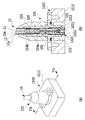
図3(a)は、インシュレータ102に嵌合部側シェル103を圧入する工程を示す斜視図であり、図3(b)は、嵌合部側シェル103のシールド線接続部103aと同軸ケーブル10のシールド線12が内側に入るように圧着側シェル104を取り付ける工程を示す斜視図であり、図3(c)は、圧着側シェル104を圧着する工程を示す斜視図である。   FIG. 3A is a perspective view showing a process of press-fitting the fitting portion side shell 103 into the insulator 102, and FIG. 3B is a diagram showing the shielded wire connecting portion 103 a of the fitting portion side shell 103 and the coaxial cable 10. FIG. 3C is a perspective view showing a process of attaching the crimping side shell 104 so that the shield wire 12 enters inside, and FIG. 3C is a perspective view showing a process of crimping the crimping side shell 104.

図3(a)に示すように、インシュレータ102の2箇所の挿入口102fの先端側に嵌合部側シェル103の2つのシールド線接続部103aが圧入される。このとき、嵌合部側シェル103の先端側に設けられた複数のガイド部103bの間に平坦な部分があるため、この平坦な部分に工具等を当てることができ、容易に嵌合部側シェル103を圧入することができる。また、シールド線接続部103aがインシュレータ102の挿入口102fに圧入されるため隙間が生じず、後述するホットメルト105を後端側に形成するときに、先端側の嵌合凹部102eにホットメルト105等の封止材料が流れ込むことを防止できる。   As shown in FIG. 3A, the two shield wire connecting portions 103a of the fitting portion side shell 103 are press-fitted into the distal end sides of the two insertion ports 102f of the insulator 102. At this time, since there is a flat portion between the plurality of guide portions 103b provided on the front end side of the fitting portion side shell 103, a tool or the like can be applied to the flat portion, and the fitting portion side can be easily The shell 103 can be press-fitted. Further, since the shield wire connecting portion 103a is press-fitted into the insertion port 102f of the insulator 102, no gap is formed, and when the hot melt 105 described later is formed on the rear end side, the hot melt 105 is inserted into the fitting recess 102e on the front end side. The sealing material such as can be prevented from flowing.

次に、図3(b)に示すように、嵌合部側シェル103のシールド線接続部103aと同軸ケーブル10のシールド線12が内側に入るように圧着側シェル104を取り付ける。その後、図3(c)に示すように、圧着側シェル104を圧着する。このとき、シールド線固定部104aは、シールド線12と、シールド線接続部103aを圧着し、同軸ケーブル固定部104bは、同軸ケーブル10の被覆12aを圧着する。シールド線固定部104a及び同軸ケーブル固定部104bは、圧着されることにより、図3(c)に示すように、先端側と後端側に2つの円柱形状を有することになる。   Next, as shown in FIG. 3B, the crimping side shell 104 is attached so that the shielded wire connecting portion 103a of the fitting portion side shell 103 and the shielded wire 12 of the coaxial cable 10 enter inside. Thereafter, as shown in FIG. 3C, the crimping side shell 104 is crimped. At this time, the shield wire fixing portion 104a crimps the shield wire 12 and the shield wire connecting portion 103a, and the coaxial cable fixing portion 104b crimps the coating 12a of the coaxial cable 10. The shield wire fixing portion 104a and the coaxial cable fixing portion 104b have two columnar shapes on the front end side and the rear end side as shown in FIG.

図4(a)は、ホットメルト105を形成する工程を示す斜視図であり、図4(b)は、ホットメルト105の形成後に、オーバーモールド106を形成する工程を示す斜視図である。   FIG. 4A is a perspective view illustrating a process of forming the hot melt 105, and FIG. 4B is a perspective view illustrating a process of forming the overmold 106 after the hot melt 105 is formed.

図4(a)に示すように、ホットメルト105がホットメルト成型により形成される。なお、ここでは、防水・防塵機能を達成するための封止材料として、ホットメルト105がホットメルト成型により形成されるものとしたが、これには限定されず、接着剤等の他の封止材料を使用してもよい。また、ホットメルト105の形状は、本実施形態の形状に限定されるものではなく、様々な形状が適用できる。次に、図4(b)に示すように、ホットメルト105が形成された後、ホットメルト105、及び、同軸ケーブル10の周囲にオーバーモールド106がオーバーモールド成型により形成される。なお、オーバーモールド106の形状も、本実施形態の形状に限定されるものではなく、様々な形状が適用できる。また、ホットメルト105として耐候性を有する材料を使用した場合には、オーバーモールド106を設ける必要はない。   As shown in FIG. 4A, the hot melt 105 is formed by hot melt molding. Here, as the sealing material for achieving the waterproof / dustproof function, the hot melt 105 is formed by hot melt molding. However, the present invention is not limited to this, and other seals such as an adhesive are used. Materials may be used. The shape of the hot melt 105 is not limited to the shape of the present embodiment, and various shapes can be applied. Next, as shown in FIG. 4B, after the hot melt 105 is formed, an overmold 106 is formed around the hot melt 105 and the coaxial cable 10 by overmolding. The shape of the overmold 106 is not limited to the shape of the present embodiment, and various shapes can be applied. In addition, when a material having weather resistance is used as the hot melt 105, it is not necessary to provide the overmold 106.

以上のように、概略上述の工程により、図1に示す同軸ケーブル用コネクタ100が製造される。なお、ここでは、同軸ケーブル10に接続される同軸ケーブル用コネクタ100を例にとり説明したが、複数の芯線を有する多芯ケーブルに接続される多芯ケーブル用コネクタに適用するものとしてもよく、この場合には、複数の芯線に接続されるコンタクト端子101は複数本となる。次に主な構成要素の単体の形状を説明する。   As described above, the coaxial cable connector 100 shown in FIG. Here, the coaxial cable connector 100 connected to the coaxial cable 10 has been described as an example, but the present invention may be applied to a multicore cable connector connected to a multicore cable having a plurality of core wires. In this case, there are a plurality of contact terminals 101 connected to a plurality of core wires. Next, the shape of a single main component will be described.

図5(a)は、コンタクト端子101を示す斜視図であり、図5(b)は、嵌合部側シェル103を示す斜視図である。   FIG. 5A is a perspective view showing the contact terminal 101, and FIG. 5B is a perspective view showing the fitting portion side shell 103.

図5(a)において、コンタクト端子101は、略円柱形状を有し、後端に、同軸ケーブル10の芯線11が挿入され、圧着される円筒部分101aと、円柱の先端と後端の間の中央付近に、コンタクト端子101がインシュレータ102の貫通孔102dに後端側から圧入されたときに係止されるフランジ部101bが形成される。なお、コンタクト端子101の形状は、本実施形態の形状に限定されず、芯線11に接続でき、インシュレータ102に圧入され、インシュレータ102の後端側から先端側にホットメルト105等の封止材料が流れ込まない形状であればよい。   In FIG. 5A, the contact terminal 101 has a substantially columnar shape. The core portion 11a of the coaxial cable 10 is inserted into the rear end of the contact terminal 101 and is crimped, and between the front end and the rear end of the column. Near the center is formed a flange portion 101b that is locked when the contact terminal 101 is press-fitted into the through hole 102d of the insulator 102 from the rear end side. In addition, the shape of the contact terminal 101 is not limited to the shape of this embodiment, can be connected to the core wire 11, is press-fitted into the insulator 102, and a sealing material such as hot melt 105 is provided from the rear end side to the front end side of the insulator 102. Any shape that does not flow in may be used.

図5(b)において、嵌合部側シェル103は、略円筒形状を有し、円筒形状の後端側には、2つの突起片であり、インシュレータ102の挿入口102fの先端側から圧入され、シールド線12に接続されるシールド線接続部103aが設けられる。また、嵌合部側シェル103の先端側には、レセプタクル1020との嵌合時にレセプタクル1020をガイドするための斜めに拡がって曲がった複数の突起部であるガイド部103bが設けられる。なお、ガイド部103bの形状は、本実施形態の形状には限定されない。また、嵌合部側シェル103の形状は、本実施形態の形状には限定されず、例えば、四角形や六角形の筒形状や、多芯ケーブルに適用する場合には、細長い長方形や楕円形の筒形状等であってもよい。また、ここでは、シールド線接続部103aを2箇所設けるものとしたが、これには限定されず、2箇所以外の複数箇所でも、バランスが悪くなるが1箇所設けられるものとしてもよい。   In FIG. 5B, the fitting portion side shell 103 has a substantially cylindrical shape, and is two projecting pieces on the rear end side of the cylindrical shape, and is press-fitted from the front end side of the insertion port 102 f of the insulator 102. , A shield wire connection portion 103a connected to the shield wire 12 is provided. In addition, a guide portion 103b, which is a plurality of projecting portions that are obliquely expanded and bent, is provided on the distal end side of the fitting portion side shell 103 to guide the receptacle 1020 when the fitting portion side shell 103 is fitted. In addition, the shape of the guide part 103b is not limited to the shape of this embodiment. Further, the shape of the fitting portion side shell 103 is not limited to the shape of the present embodiment. For example, when applied to a quadrangular or hexagonal tubular shape, or a multi-core cable, the shape of the elongated rectangular shape or the elliptical shape. A cylindrical shape etc. may be sufficient. Here, two shield wire connection portions 103a are provided. However, the present invention is not limited to this, and a plurality of locations other than the two locations may have a poor balance, but may be provided at one location.

図6(a)は、同軸ケーブル用コネクタ100が車載カメラモジュール1000に嵌合された状態を示す斜視図であり、図6(b)は、図6(a)に示すVIb−VIb線に沿った断面図である。   FIG. 6A is a perspective view showing a state in which the coaxial cable connector 100 is fitted to the in-vehicle camera module 1000, and FIG. 6B is along the line VIb-VIb shown in FIG. FIG.

図6(b)において、レセプタクル1020は、同軸ケーブル用コネクタ100のコンタクト端子101とコネクタ嵌合時に電気的に接触されるレセプタクルコンタクト端子1021と、レセプタクルコンタクト端子1021の周囲を絶縁して保持するレセプタクルインシュレータ1022と、レセプタクルインシュレータ1022の周囲に配置され、嵌合部側シェル103とコネクタ嵌合時に電気的に接触されるレセプタクルGND1023と備える。なお、レセプタクル1020の形状は、本実施形態の形状には限定されない。   6B, a receptacle 1020 includes a receptacle contact terminal 1021 that is electrically contacted with the contact terminal 101 of the coaxial cable connector 100 when the connector is fitted, and a receptacle that insulates and holds the periphery of the receptacle contact terminal 1021. An insulator 1022 and a receptacle GND 1023 disposed around the receptacle insulator 1022 and electrically contacted with the fitting portion side shell 103 when the connector is fitted are provided. Note that the shape of the receptacle 1020 is not limited to the shape of the present embodiment.

図6(a)及び図6(b)において、同軸ケーブル用コネクタ100は、車載カメラモジュール1000のケーブル側ケース1010にねじ止めなどにより固定される。なお、本実施形態の同軸ケーブル用コネクタ100は、レセプタクル1020が実装された実装基板(図示を省略する。)が装着されたモジュール側ケース(図示を省略する。)と、ケーブル側ケース1010が組み合わされた車載カメラモジュール1000に直接嵌合することを想定している。このとき、左右方向の取り付け誤差は、インシュレータ102のねじ止め穴102aの径を大きくすることにより吸収できる。また、上下方向の取り付け誤差は、同軸ケーブル用コネクタ100のコンタクト端子101及び嵌合部側シェル103と、レセプタクル1020のレセプタクルコンタクト端子1021及びレセプタクルGND1023の嵌合ストロークにより吸収できる。   6A and 6B, the coaxial cable connector 100 is fixed to the cable side case 1010 of the in-vehicle camera module 1000 by screwing or the like. The coaxial cable connector 100 of the present embodiment is a combination of a module side case (not shown) on which a mounting board (not shown) on which a receptacle 1020 is mounted and a cable side case 1010 are combined. It is assumed that the vehicle-mounted camera module 1000 is directly fitted. At this time, the mounting error in the left-right direction can be absorbed by increasing the diameter of the screwing hole 102 a of the insulator 102. Further, the mounting error in the vertical direction can be absorbed by the fitting stroke of the contact terminal 101 and the fitting portion side shell 103 of the coaxial cable connector 100 and the receptacle contact terminal 1021 and the receptacle GND 1023 of the receptacle 1020.

なお、以上のように、本発明のケーブル用コネクタを、主に同軸ケーブル用コネクタ100を例にとり説明してきたが、上述したように、同軸ケーブル以外のシールド線付き多芯ケーブル等に接続可能な、防水・防塵機能を必要とするケーブル用コネクタ全般に適用可能である。   As described above, the cable connector of the present invention has been described mainly using the coaxial cable connector 100 as an example. However, as described above, it can be connected to a multi-core cable with a shielded wire other than the coaxial cable. It can be applied to all cable connectors that require waterproof and dustproof functions.

以上のように本発明のケーブル用コネクタによれば、防水・防塵機能を目的とした封止材料の流れ込みを防止しつつ、部品点数及び作業工数を削減し、コストを削減できる。   As described above, according to the cable connector of the present invention, the number of parts and work man-hours can be reduced and the cost can be reduced while preventing the sealing material from flowing in for the purpose of waterproof and dustproof functions.

10 同軸ケーブル
11 芯線
11a 絶縁材
12 シールド線
12a 被覆
100 同軸ケーブル用コネクタ
101 コンタクト端子
101a 円筒部分
101b、102c フランジ部
102 インシュレータ
102a ねじ止め穴
102b 突起部
102d 貫通孔
102e 嵌合凹部
102f 挿入口
102g 係合穴
102h 円板形状係合部
102i 円環溝
103 嵌合部側シェル
103a シールド線接続部
103b ガイド部
104 圧着側シェル
104a シールド線固定部
104b 同軸ケーブル固定部
105 ホットメルト
106 オーバーモールド
107 Oリング
1000 車載カメラモジュール
1010 ケーブル側ケース
1020 レセプタクル
1021 レセプタクルコンタクト端子
1022 レセプタクルインシュレータ
1023 レセプタクルGND
DESCRIPTION OF SYMBOLS 10 Coaxial cable 11 Core wire 11a Insulation material 12 Shield wire 12a Coating | cover 100 Connector for coaxial cables 101 Contact terminal 101a Cylindrical part 101b, 102c Flange part 102 Insulator 102a Screwing hole 102b Protrusion part 102d Through-hole 102e Fitting recessed part 102f Insertion opening 102g Engagement Joint hole 102h Disc-shaped engaging portion 102i Annular groove 103 Fitting portion side shell 103a Shield wire connecting portion 103b Guide portion 104 Crimp side shell 104a Shield wire fixing portion 104b Coaxial cable fixing portion 105 Hot melt 106 Overmold 107 O-ring 1000 In-vehicle camera module 1010 Cable side case 1020 Receptacle 1021 Receptacle contact terminal 1022 Receptacle insulator 10 23 Receptacle GND

Claims (6)

少なくとも1つの芯線、及び、前記少なくとも1つの芯線の周囲に絶縁材を介して覆うシールド線を備えるケーブルに接続され、レセプタクルと嵌合されるケーブル用コネクタであって、
前記少なくとも1つの芯線に接続される少なくとも1つのコンタクト端子と、
前記少なくとも1つのコンタクト端子が挿入されるインシュレータと、
前記ケーブル側に、少なくとも1つの突起片であり、前記インシュレータのレセプタクル側から挿入され、前記シールド線に接続されるシールド線接続部を有する嵌合部側シェルと、
前記インシュレータの前記ケーブル側に配置され、前記少なくとも1つのコンタクト端子、前記嵌合部側シェル、前記少なくとも1つの芯線、及び、前記シールド線を含む部材を覆う封止材料と
を備えるケーブル用コネクタ。
A cable connector that is connected to a cable having at least one core wire and a shield wire that covers the periphery of the at least one core wire via an insulating material and is fitted to a receptacle,
At least one contact terminal connected to the at least one core wire;
An insulator into which the at least one contact terminal is inserted;
On the cable side, there is at least one protruding piece, inserted from the receptacle side of the insulator, and a fitting portion side shell having a shield wire connecting portion connected to the shield wire;
A cable connector comprising: a sealing material disposed on the cable side of the insulator and covering the member including the at least one contact terminal, the fitting portion side shell, the at least one core wire, and the shield wire.
前記シールド線、及び、前記シールド線に接続された前記嵌合部側シェルの前記シールド線接続部を固定する圧着側シェルをさらに備えることを特徴とする請求項1に記載のケーブル用コネクタ。   The cable connector according to claim 1, further comprising a crimp-side shell that fixes the shielded wire and the shielded wire connecting portion of the fitting portion-side shell connected to the shielded wire. 前記封止材料及びケーブルの周囲に形成される耐候性を有するオーバーモールドをさらに備えることを特徴とする請求項1に記載のケーブル用コネクタ。   The cable connector according to claim 1, further comprising an overmold having weather resistance formed around the sealing material and the cable. 前記封止材料は、ホットメルト成型により形成されることを特徴とする請求項1に記載のケーブル用コネクタ。   The cable connector according to claim 1, wherein the sealing material is formed by hot melt molding. 前記インシュレータの前記ケーブル側には、前記封止材料が係合し、防水・防塵機能を補完するための係合部が設けられることを特徴とする請求項1に記載のケーブル用コネクタ。   2. The cable connector according to claim 1, wherein an engagement portion is provided on the cable side of the insulator to engage the sealing material and supplement a waterproof / dustproof function. 前記ケーブルは、同軸ケーブルであり、前記ケーブル用コネクタは、同軸ケーブル用コネクタであることを特徴とする請求項1に記載のケーブル用コネクタ。   The cable connector according to claim 1, wherein the cable is a coaxial cable, and the cable connector is a coaxial cable connector.
JP2016101323A 2016-05-20 2016-05-20 Connector for cable Pending JP2017208286A (en)

Priority Applications (1)

Application Number Priority Date Filing Date Title
JP2016101323A JP2017208286A (en) 2016-05-20 2016-05-20 Connector for cable

Applications Claiming Priority (1)

Application Number Priority Date Filing Date Title
JP2016101323A JP2017208286A (en) 2016-05-20 2016-05-20 Connector for cable

Publications (1)

Publication Number Publication Date
JP2017208286A true JP2017208286A (en) 2017-11-24

Family

ID=60415615

Family Applications (1)

Application Number Title Priority Date Filing Date
JP2016101323A Pending JP2017208286A (en) 2016-05-20 2016-05-20 Connector for cable

Country Status (1)

Country Link
JP (1) JP2017208286A (en)

Cited By (1)

* Cited by examiner, † Cited by third party
Publication number Priority date Publication date Assignee Title
US11824299B2 (en) 2018-10-01 2023-11-21 Sony Semiconductor Solutions Corporation Connector

Cited By (1)

* Cited by examiner, † Cited by third party
Publication number Priority date Publication date Assignee Title
US11824299B2 (en) 2018-10-01 2023-11-21 Sony Semiconductor Solutions Corporation Connector

Similar Documents

Publication Publication Date Title
US11700444B2 (en) Vehicular camera having tolerance accommodating electric ally-conductive connection
CN107565246B (en) Connector module and vehicle-mounted camera using the same
US7922526B2 (en) Electrical equipment
US10224666B2 (en) Packing and shield connector
US9703176B2 (en) Camera module for providing operational convenience
US9190767B2 (en) Electrical connection structure between module device and an external device
JP2018107036A (en) Receptacle connector and camera unit
US20190103716A1 (en) Connector module and onboard camera using the same
JP4601485B2 (en) Electrical equipment
US10593716B2 (en) Electronic component and imaging device comprising an external device connection having a case portion connection portion and an external conductor connection portion
JP6779123B2 (en) Receptacle connector and connector
JP6555065B2 (en) Module connector
CN110214397B (en) Module connector
US7347730B2 (en) Grommet
JP4590467B2 (en) connector
JP2017208286A (en) Connector for cable
JP2011009108A (en) Shield connector
JP2002373730A (en) Mold connector
JP4278846B2 (en) Shield connector for device connection
JP2017092020A (en) Module connector
JP2005310531A (en) Electric equipment
KR20150000613A (en) Camera module
JP4369602B2 (en) Shield connector for device connection
WO2017082080A1 (en) Module connector
JP2002334751A (en) Shield connector for equipment

Legal Events

Date Code Title Description
A621 Written request for application examination

Free format text: JAPANESE INTERMEDIATE CODE: A621

Effective date: 20190408

A131 Notification of reasons for refusal

Free format text: JAPANESE INTERMEDIATE CODE: A131

Effective date: 20191224

A977 Report on retrieval

Free format text: JAPANESE INTERMEDIATE CODE: A971007

Effective date: 20191220

A02 Decision of refusal

Free format text: JAPANESE INTERMEDIATE CODE: A02

Effective date: 20200630