JP2017205700A - Water treatment method and water treatment device - Google Patents
Water treatment method and water treatment device Download PDFInfo
- Publication number
- JP2017205700A JP2017205700A JP2016099265A JP2016099265A JP2017205700A JP 2017205700 A JP2017205700 A JP 2017205700A JP 2016099265 A JP2016099265 A JP 2016099265A JP 2016099265 A JP2016099265 A JP 2016099265A JP 2017205700 A JP2017205700 A JP 2017205700A
- Authority
- JP
- Japan
- Prior art keywords
- water
- treated
- ultraviolet
- light
- light source
- Prior art date
- Legal status (The legal status is an assumption and is not a legal conclusion. Google has not performed a legal analysis and makes no representation as to the accuracy of the status listed.)
- Granted
Links
Images


Abstract
Description
本発明は、水処理方法および水処理装置に関する。更に詳しくは、残留塩素を含有する水を処理対象とする水処理方法および水処理装置に関する。 The present invention relates to a water treatment method and a water treatment apparatus. More specifically, the present invention relates to a water treatment method and a water treatment apparatus for treating water containing residual chlorine.
医薬用純水(精製水)や産業用純水(具体的には、例えば半導体製造用超純水等)は、水道水を原水とするものであり、原水である水道水を、逆浸透膜分離装置および脱イオン装置(具体的には、例えばイオン交換装置および脱電気イオン装置等)などによって処理することによって製造される。
一方、我が国において、水道水は、塩素処理によって消毒されており、また一般細菌の増殖防止のために、残留塩素が含まれている。水道水における残留塩素の濃度は、0.5mg/L程度とされている。
Pharmaceutical pure water (purified water) and industrial pure water (specifically, ultrapure water for semiconductor production, for example) are produced using tap water as raw water, and tap water that is raw water is converted into a reverse osmosis membrane. It is manufactured by processing with a separation device and a deionization device (specifically, for example, an ion exchange device and a deionization ion device).
On the other hand, in Japan, tap water is sterilized by chlorination and contains residual chlorine to prevent the growth of general bacteria. The concentration of residual chlorine in tap water is about 0.5 mg / L.
医薬用純水や産業用純水を製造するための水処理システムにおいては、水道水中の残留塩素による、逆浸透膜分離装置および脱イオン装置などの装置の酸化劣化を防止するために、これらの装置の前段において、水道水中の残留塩素を除去処理している。
一般的に、残留塩素の除去処理の手法としては、水道水を活性炭によって濾過する手法、水道水に重亜硫酸ナトリウムなどの還元剤を注入する手法、および、水道水に紫外線(具体的には、例えば波長254nmの紫外線)を照射する手法などが挙げられる。
In water treatment systems for producing pharmaceutical pure water and industrial pure water, in order to prevent oxidative deterioration of devices such as reverse osmosis membrane separation devices and deionization devices due to residual chlorine in tap water, In the previous stage of the equipment, residual chlorine in tap water is removed.
In general, residual chlorine removal methods include a method of filtering tap water with activated carbon, a method of injecting a reducing agent such as sodium bisulfite into tap water, and ultraviolet rays (specifically, For example, a method of irradiating ultraviolet rays having a wavelength of 254 nm may be used.
そして、医薬用純水や産業用純水を製造するための水処理システムにおいて、水道水に紫外線を照射する手法としては、紫外線光源として中圧水銀ランプを用いる手法、すなわち中圧水銀ランプを備えた水処理装置を用いることが提案されている(例えば、特許文献1参照。)。ここに、中圧水銀ランプとは、水銀蒸気圧が0.04〜4MPaの水銀ランプを示す。 In a water treatment system for producing pharmaceutical pure water or industrial pure water, as a method of irradiating tap water with ultraviolet light, a method using a medium pressure mercury lamp as an ultraviolet light source, that is, a medium pressure mercury lamp is provided. It has been proposed to use a water treatment apparatus (see, for example, Patent Document 1). Here, the medium pressure mercury lamp refers to a mercury lamp having a mercury vapor pressure of 0.04 to 4 MPa.
しかしながら、水道水に中圧水銀ランプからの紫外線を照射する手法においては、残留塩素を効率よく分解除去することができない、具体的には、消費電力あたりの残留塩素分解率が低い、という問題がある。
また、水処理システムにおいては、中圧水銀ランプが、ランプ温度が高温(具体的には、おおよそ600℃)となるものであることから、被処理水は高温となった中圧水銀ランプからの伝熱を受けて加温し、それに起因して後段の装置(具体的には、ポリアミドまたは酢酸セルロールよりなる逆浸透膜を備えた逆浸透膜分離装置)を劣化させるおそれがある。
However, the method of irradiating ultraviolet rays from a medium-pressure mercury lamp to tap water cannot efficiently decompose and remove residual chlorine. Specifically, there is a problem that the residual chlorine decomposition rate per power consumption is low. is there.
Further, in the water treatment system, the medium pressure mercury lamp has a high temperature (specifically, approximately 600 ° C.), so that the water to be treated is from the medium pressure mercury lamp having a high temperature. There is a risk of heating and receiving heat transfer, resulting in deterioration of the latter device (specifically, a reverse osmosis membrane separation device having a reverse osmosis membrane made of polyamide or cellulose acetate).
本発明は、以上のような事情に基づいてなされたものであって、その目的は、得られる処理済水を処理対象とする装置の劣化を抑制しつつ、被処理水中の有効塩素を効率的に除去処理することのできる水処理方法および水処理装置を提供することにある。 The present invention has been made based on the circumstances as described above, and the object thereof is to efficiently reduce the effective chlorine in the water to be treated while suppressing deterioration of the apparatus that treats the obtained treated water as a treatment target. Another object of the present invention is to provide a water treatment method and a water treatment apparatus that can be removed.
本発明の水処理方法は、紫外線光源から放射された波長190〜200nmの範囲に主発光波長を有する光を被処理水に照射することにより、当該被処理水中に含まれる有効塩素を除去処理することを特徴とする。 The water treatment method of the present invention removes effective chlorine contained in the water to be treated by irradiating the water to be treated with light having a main emission wavelength in a wavelength range of 190 to 200 nm emitted from an ultraviolet light source. It is characterized by that.
本発明の水処理方法においては、前記被処理水に照射される前記紫外線光源から放射された光は、更に波長170〜180nmの範囲に発光波長を有することが好ましい。 In the water treatment method of the present invention, it is preferable that the light emitted from the ultraviolet light source irradiated to the water to be treated has a light emission wavelength in a wavelength range of 170 to 180 nm.
本発明の水処理装置は、波長190〜200nmの範囲に主発光波長を有する光を放射する紫外線光源と、当該紫外線光源から放射された光を被処理水に照射するための紫外線照射機構とを備えており、被処理水中に含まれる有効塩素を除去処理することを特徴とする。 The water treatment apparatus of the present invention includes an ultraviolet light source that emits light having a main emission wavelength in a wavelength range of 190 to 200 nm, and an ultraviolet irradiation mechanism for irradiating the water to be treated with the light emitted from the ultraviolet light source. It is characterized by removing effective chlorine contained in the water to be treated.
本発明の水処理装置においては、前記紫外線光源は、波長170〜180nmの範囲に更に発光波長を有する光を放射することが好ましい。 In the water treatment apparatus of the present invention, the ultraviolet light source preferably emits light having a light emission wavelength in the wavelength range of 170 to 180 nm.
本発明の水処理方法においては、被処理水に対して、紫外線光源から放射された波長190〜200nmの範囲に主発光波長を有する特定の光が照射される。そして、その特定の光における波長190〜200nmの範囲の光は、水に吸収されにくく、有効塩素に吸収されやすい光である。そのため、被処理水中の有効塩素を、大きな放射照度を要することなく、短時間で分解することができる。
従って、本発明の水処理方法によれば、被処理水を過度に加温することなく、有効塩素を効率よく分解することができることから、得られる処理済水を処理対象とする装置の劣化を抑制しつつ、被処理水中の有効塩素を効率的に除去処理することができる。
In the water treatment method of the present invention, the water to be treated is irradiated with specific light having a main emission wavelength in a wavelength range of 190 to 200 nm emitted from an ultraviolet light source. And the light of the wavelength of 190-200 nm in the specific light is light which is hard to be absorbed by water and is easy to be absorbed by effective chlorine. Therefore, effective chlorine in the for-treatment water can be decomposed in a short time without requiring large irradiance.
Therefore, according to the water treatment method of the present invention, effective chlorine can be efficiently decomposed without excessively heating the water to be treated. Effective chlorine in the water to be treated can be efficiently removed while being suppressed.
本発明の水処理装置は、波長190〜200nmの範囲に主発光波長を有する光を放射する紫外線光源と、当該紫外線光源から放射された光を被処理水に照射するための紫外線照射機構とを備えたものであることから、本発明の水処理方法を実施することができる。そのため、本発明の水処理装置によれば、得られる処理済水を処理対象とする装置の劣化を抑制しつつ、被処理水中の有効塩素を効率的に除去処理することができる。 The water treatment apparatus of the present invention includes an ultraviolet light source that emits light having a main emission wavelength in a wavelength range of 190 to 200 nm, and an ultraviolet irradiation mechanism for irradiating the water to be treated with the light emitted from the ultraviolet light source. Since it is provided, the water treatment method of the present invention can be carried out. Therefore, according to the water treatment apparatus of the present invention, effective chlorine in the for-treatment water can be efficiently removed while suppressing deterioration of the apparatus for treating the obtained treated water.
以下、本発明の水処理方法および水処理装置の実施の形態について説明する。 Hereinafter, embodiments of the water treatment method and the water treatment apparatus of the present invention will be described.
本発明の水処理方法は、水道水などの残留塩素(有効塩素)を含有する水を被処理水とするものであり、被処理水中、すなわち残留塩素を含有する水中に含まれる残留塩素を除去処理するものである。ここに、本明細書中において、「残留塩素」とは、水道水などの塩素処理された水中に残留する有効塩素を示し、また「有効塩素」とは、殺菌効力を有する塩素(具体的には、次亜塩素酸(HClO)および次亜塩素酸ナトリウム(次亜塩素酸イオン(ClO- ))など)を示す。この本発明の水処理方法に供される被処理水は、少なくとも有効塩素を含有するものであればよく、有効塩素以外の成分が含有されたものであってもよい。
そして、本発明の水処理方法は、被処理水に対して紫外線を照射する紫外線照射工程を有するものである。この紫外線照射工程においては、被処理水に対して、残留塩素を分解する残留塩素除去処理が行われる。
The water treatment method of the present invention uses water containing residual chlorine (effective chlorine) such as tap water as water to be treated, and removes residual chlorine contained in water to be treated, that is, water containing residual chlorine. It is something to process. Here, in this specification, “residual chlorine” refers to effective chlorine remaining in chlorinated water such as tap water, and “effective chlorine” refers to chlorine having a bactericidal effect (specifically, Indicates hypochlorous acid (HClO) and sodium hypochlorite (such as hypochlorite ion (ClO − )). The water to be treated to be used in the water treatment method of the present invention only needs to contain at least effective chlorine, and may contain components other than effective chlorine.
And the water treatment method of this invention has an ultraviolet irradiation process of irradiating a to-be-processed water with an ultraviolet-ray. In this ultraviolet irradiation process, residual chlorine removal treatment for decomposing residual chlorine is performed on the water to be treated.
本発明の水処理方法の紫外線照射工程において、被処理水に照射する紫外線は、波長190〜200nmの範囲に主発光波長を有する光を放射する紫外線光源から放射された光である。ここに、本明細書中において、「主発光波長」とは、最も出力(発光強度)の高い波長を示す。
すなわち、紫外線照射工程においては、被処理水に対して、波長190〜200nmの範囲にピーク波長を有する光が照射される。
被処理水に対して、紫外線光源から放射された波長190〜200nmの範囲に主発光波長を有する光を照射することにより、後述の実験例から明らかなように、被処理水中の残留塩素を効率的に除去処理することができる。
In the ultraviolet irradiation step of the water treatment method of the present invention, the ultraviolet rays irradiated to the water to be treated are light emitted from an ultraviolet light source that emits light having a main emission wavelength in a wavelength range of 190 to 200 nm. Here, in the present specification, the “main emission wavelength” indicates a wavelength having the highest output (emission intensity).
In other words, in the ultraviolet irradiation process, the water to be treated is irradiated with light having a peak wavelength in a wavelength range of 190 to 200 nm.
By irradiating the water to be treated with light having a main emission wavelength in the wavelength range of 190 to 200 nm emitted from the ultraviolet light source, the residual chlorine in the water to be treated is efficiently removed as will be apparent from the experimental examples described later. Can be removed.
また、被処理水に照射される紫外線光源から放射された光は、更に波長170〜180nmの範囲に発光波長を有する、すなわち波長190〜200nmの範囲に第1の発光波長(主発光波長)を有すると共に、波長170〜180nmの範囲に第2の発光波長を有するものであることが好ましい。ここに、本明細書中において、「第2の発光波長」とは、波長190nm以下の波長範囲において、主発光波長(第1の発光波長)に次ぐ2番目に出力(発光強度)の高い波長を示す。
被処理水に対して、紫外線光源から放射された波長170〜180nmの範囲に第2の発光波長を有する光が照射されることによれば、後述の実験例から明らかなように、被処理水中の残留塩素を、より一層効率的に除去処理することができる。
その理由について以下に説明する。
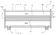
波長170〜180nmの光(紫外線)は、図1に示すように、水に吸収されやすい光であり、この波長170〜180nmの光が水に吸収されることによれば、ヒドロキシラジカルが生成する。ここに、図1は、水の紫外線透過スペクトルであって、水層の厚み(光(紫外線)の透過方向の厚み)が1mmの条件によって測定されたものである。この水の紫外光透過スペクトルにおいては、水の透過率の変曲点が波長189nmに存在することが示されている。そして、ヒドロキシラジカルは、残留塩素に作用して残留塩素を分解するものである。そのため、被処理水に対して、波長190〜200nmの範囲に主発光波長(第1の発光波長)を有すると共に、波長170〜180nmの範囲に第2の発光波長を有する光が照射されることにより、当該被処理水中に含まれる残留塩素が、紫外線光源から放射された光(具体的には、主として波長190〜200nmの範囲の光)の直接的な作用、および、当該紫外線光源から放射された光(具体的には、主として波長170〜180nmの範囲の光)の間接的な作用によって分解される。
In addition, the light emitted from the ultraviolet light source irradiated to the water to be treated has a light emission wavelength in the wavelength range of 170 to 180 nm, that is, the first light emission wavelength (main light emission wavelength) in the wavelength range of 190 to 200 nm. In addition, it is preferable to have a second emission wavelength in the wavelength range of 170 to 180 nm. Here, in the present specification, the “second emission wavelength” is the wavelength having the second highest output (emission intensity) after the main emission wavelength (first emission wavelength) in the wavelength range of 190 nm or less. Indicates.
By irradiating the water to be treated with light having the second emission wavelength in the wavelength range of 170 to 180 nm emitted from the ultraviolet light source, as will be apparent from the experimental examples described later, The residual chlorine can be removed more efficiently.
The reason will be described below.
As shown in FIG. 1, light (ultraviolet light) having a wavelength of 170 to 180 nm is light that is easily absorbed by water, and when this light having a wavelength of 170 to 180 nm is absorbed by water, a hydroxy radical is generated. . Here, FIG. 1 is an ultraviolet transmission spectrum of water, and is measured under the condition that the thickness of the water layer (thickness in the transmission direction of light (ultraviolet rays)) is 1 mm. In the ultraviolet light transmission spectrum of water, it is shown that the inflection point of water transmittance exists at a wavelength of 189 nm. And a hydroxy radical acts on residual chlorine and decomposes | disassembles residual chlorine. Therefore, the water to be treated is irradiated with light having a main emission wavelength (first emission wavelength) in the wavelength range of 190 to 200 nm and a second emission wavelength in the wavelength range of 170 to 180 nm. Thus, residual chlorine contained in the water to be treated is directly emitted from the light emitted from the ultraviolet light source (specifically, mainly in the wavelength range of 190 to 200 nm) and emitted from the ultraviolet light source. The light is decomposed by the indirect action of light (specifically, light mainly in the wavelength range of 170 to 180 nm).
紫外線光源としては、紫外線放射ランプ、具体的には波長190〜200nmの範囲に主発光波長を有する光を放射する紫外線放射ランプ(以下、「特定紫外線放射ランプ」ともいう。)が好適に用いられる。この特定紫外線放射ランプは、波長190〜200nmの範囲に主発光波長(第1の発光波長)を有すると共に、波長170〜180nmの範囲に第2の発光波長を有する紫外線を放射するものであることが好ましい。
特定紫外線放射ランプの好ましい具体例としては、発光ガスとしてキセノンガスなどの希ガスが封入された発光管の外周面に一対の電極が配設され、当該発光管の内面に、蛍光体としてネオジウム付活リン酸イットリウムを含有する蛍光体層が形成された蛍光体ランプが挙げられる。
また、特定紫外線放射ランプとしては、ArFランプ(波長193nmの単色光を放射するエキシマランプであって、例えば特開2009−301863号公報に記載のArFランプ)などを用いることもできる。
更に、紫外線光源としては、波長190〜200nmの範囲に主発光波長を有するLED素子を用いることもできる。
As the ultraviolet light source, an ultraviolet radiation lamp, specifically, an ultraviolet radiation lamp that emits light having a main emission wavelength in the wavelength range of 190 to 200 nm (hereinafter also referred to as “specific ultraviolet radiation lamp”) is preferably used. . This specific ultraviolet radiation lamp has a main emission wavelength (first emission wavelength) in a wavelength range of 190 to 200 nm and emits ultraviolet rays having a second emission wavelength in a wavelength range of 170 to 180 nm. Is preferred.
As a preferred specific example of the specific ultraviolet radiation lamp, a pair of electrodes are disposed on the outer peripheral surface of a luminous tube in which a rare gas such as xenon gas is enclosed as a luminous gas, and neodymium is attached to the inner surface of the luminous tube as a phosphor. A phosphor lamp in which a phosphor layer containing active yttrium phosphate is formed.
Further, as the specific ultraviolet radiation lamp, an ArF lamp (an excimer lamp that emits monochromatic light having a wavelength of 193 nm, for example, an ArF lamp described in Japanese Patent Laid-Open No. 2009-301863) may be used.
Furthermore, as the ultraviolet light source, an LED element having a main emission wavelength in a wavelength range of 190 to 200 nm can be used.
この紫外線照射工程において、被処理水に対する紫外線の紫外線照射量は、紫外線光源の種類、被処理水における残留塩素の量、残留塩素除去処理によって得られる処理済水(残留塩素除去処理された被処理水)において必要とされる残留塩素の量などに応じて、適宜に定められる。 In this ultraviolet irradiation process, the ultraviolet irradiation amount of the ultraviolet rays to the water to be treated is the type of the ultraviolet light source, the amount of residual chlorine in the water to be treated, the treated water obtained by the residual chlorine removal treatment (the treatment subject to residual chlorine removal treatment It is appropriately determined according to the amount of residual chlorine required in water).
このような本発明の水処理方法は、本発明の水処理装置によって好適に実施することができる。
本発明の水処理装置は、波長190〜200nmの範囲に主発光波長を有する光を放射する紫外線光源と、当該紫外線光源から放射された光を被処理水に照射するための紫外線照射機構とを備えたものである。
Such a water treatment method of the present invention can be preferably carried out by the water treatment apparatus of the present invention.
The water treatment apparatus of the present invention includes an ultraviolet light source that emits light having a main emission wavelength in a wavelength range of 190 to 200 nm, and an ultraviolet irradiation mechanism for irradiating the water to be treated with the light emitted from the ultraviolet light source. It is provided.
図2は、本発明の水処理装置の構成の一例を示す説明図であり、図3は、図2のA−A線断面を示す説明用断面図である。
この水処理装置10は、円筒状の被処理水収容容器(以下、「管状容器」ともいう。)11と、この管状容器11内に配置された円柱状の紫外線光源(紫外線放射ランプ20)と、当該管状容器11内において、紫外線光源を包囲するように設けられた紫外線透過性光源保護部材(以下、「光源保護管」ともいう。)12とを備えてなるものである。そして、水処理装置10においては、管状容器11と光源保護管12とにより、紫外線光源から放射された光を被処理水に照射するための紫外線照射機構が構成されている。
この図の例において、紫外線光源としては、両端に封止部を有する直円筒状の発光管を備え、この発光管の内部に円柱状の放電空間よりなる紫外線発生部が形成された紫外線放射ランプ20が用いられている。この紫外線放射ランプ20は、発光ガスとしてキセノンガスが封入され、波長190〜200nmの範囲に主発光波長(第1の発光波長)を有すると共に、波長170〜180nmに第2の発光波長を有する光を放射する蛍光体ランプ(以下、「特定蛍光体ランプ」ともいう。)である。
FIG. 2 is an explanatory view showing an example of the configuration of the water treatment apparatus of the present invention, and FIG. 3 is an explanatory cross-sectional view showing a cross section taken along line AA of FIG.
The
In the example of this figure, as an ultraviolet light source, an ultraviolet radiation lamp provided with a straight cylindrical arc tube having sealing portions at both ends, and an ultraviolet ray generating portion comprising a columnar discharge space is formed inside the arc tube. 20 is used. The
管状容器11は、例えばステンレス鋼などの金属材料よりなり、円筒状の筒状本体11Aの両端が、閉塞部材11B,11Cによって閉塞されたものである。この管状容器11の内部には、両端が閉塞部材11B,11Cによって閉塞された円筒状の光源保護管12が配設されており、この光源保護管12は、管状容器11(筒状本体11A)の内径より小さい外径を有すると共に筒状本体11Aの全長と同等の全長を有している。また、光源保護管12は、管状容器11内において、当該光源保護管12の管軸が管状容器11(筒状本体11A)の管軸Cと一致するように支持部材(図示省略)によって支持されている。また、管状容器11には、筒状本体11Aにおける一方の閉塞部材11Bに近接した領域に、被処理水供給口13が形成されており、また筒状本体11Aにおける他方の閉塞部材11Cに近接した領域に、被処理水排出口14が形成されている。そして、管状容器11と光源保護管12との間の円環状の空間によって被処理水が収容される被処理水収容部Rwが形成されている。
The
光源保護管12は、例えば石英ガラスなどの紫外線透過性材料よりなるものである。また、光源保護管12の内部には、当該光源保護管12の管軸に沿って紫外線放射ランプ20が配設されている。この紫外線放射ランプ20は、光源保護管12の内径よりも小さい外径を有すると共に光源保護管12の全長と同等の全長を有しており、光源保護管12の内部において、当該紫外線放射ランプ20の管軸(ランプ中心軸)が光源保護管12の管軸と一致するように支持部材(図示省略)によって支持されている。すなわち、紫外線放射ランプ20は、当該紫外線放射ランプ20の管軸(ランプ中心軸)が管状容器11(筒状本体11A)の管軸Cと一致し、被処理水収容部Rwに囲まれるように配設されている。
この図の例において、紫外線放射ランプ20と光源保護管12との間の空間は、窒素ガスなどの不活性ガスで満たされている。すなわち、紫外線放射ランプ20と光源保護管12との間には、不活性ガス層が形成されている。紫外線放射ランプ20と光源保護管12との間の空間が不活性ガスで満たされていることにより、当該空間において、オゾンなどの活性ガスが発生するおそれがなくなり、水処理装置10の劣化を抑制することができる。また、紫外線放射ランプ20から放射された光(紫外線)が、紫外線放射ランプ20と光源保護管12との間の空間に存在するガス(具体的には、例えば酸素などの紫外線吸収ガス)に吸収されることに起因して、被処理水に対する紫外線照射量が減少するおそれがない。この不活性ガス層の厚み、すなわち紫外線放射ランプ20と光源保護管12との間の距離d1は、例えば10mmである。このようにして、紫外線照射機構は、紫外線放射ランプ20から放射された光が紫外線吸収ガスを含有する紫外線吸収ガス層(具体的には、大気層など)を介することなく被処理水に照射する構成のものとされている。
The light
In the example of this figure, the space between the
光源保護管12としては、例えば、合成石英ガラス(具体的には、例えば「Suprasil−F310」(信越石英株式会社))よりなるガラス管が用いられる。
As the light
また、水処理装置10において、被処理水収容部Rwにおける光路長、すなわち管状容器11(筒状本体11A)の内周面と光源保護管12の外周面との間の距離d2、被処理水収容部Rwにおける紫外線放射ランプ20から放射された光が照射される領域の大きさ(紫外線放射ランプ20の発光長)およびその他の条件は、被処理水収容部Rwに供給される被処理水の残留塩素の量、および当該水処理装置10によって処理(残留塩素除去処理)された被処理水(処理済水)において必要とされる残留塩素の量などに応じて適宜に設定される。
Moreover, in the
この水処理装置10においては、残留塩素除去処理中には、先ず、被処理水が被処理水供給口13を介して管状容器11内に供給されることによって当該管状容器11内に被処理水が充填収容された状態とされる。次いで、紫外線放射ランプ20が点灯されることにより、管状容器11内の被処理水収容部Rwに収容されている被処理水に対して、紫外線放射ランプ20から放射された光が、紫外線放射ランプ20と光源保護管12との間の不活性ガス層および光源保護管12を介して照射される。そして、このようにして紫外線放射ランプ20から放射された光が照射された被処理水、すなわち処理済水は、紫外線放射ランプ20が消灯された後、被処理水排出口14を介して管状容器11の外部に排出される。
In the
而して、水処理装置10においては、被処理水に対して、紫外線放射ランプ20から放射された波長190〜200nmに主発光波長域を有する光が照射される。すなわち、本発明の水処理方法によって残留塩素除去処理が行われる。而して、本発明の水処理方法においては、波長190〜200nmの範囲の光が、図1に示されているように水に吸収されにくく、かつ残留塩素に吸収されやすい光であることから、被処理水中の残留塩素を、大きな放射照度を要することなく、短時間で分解することができる。すなわち、紫外線放射ランプ20における消費電力あたりの残留塩素分解率が大きくなる。そして、大きな放射照度を要することなく短時間で残留塩素を分解できることによれば、紫外線放射ランプ20からの伝熱を受けることに起因する被処理水の温度上昇を抑制することができる。
従って、本発明の水処理方法によって残留塩素除去処理が行われる水処理装置10によれば、被処理水を過度に加温することなく、残留塩素を効率よく分解することができる。そのため、得られる処理済水を処理対象とする装置(具体的には、例えばイオン交換装置および脱電気イオン装置等)の劣化を抑制しつつ、被処理水中の残留塩素を効率的に除去処理することができる。
Thus, in the
Therefore, according to the
また、水処理装置10においては、紫外線放射ランプ20として、特定蛍光体ランプが用いられており、しかも、紫外線照射機構が、被処理水に対して、紫外線放射ランプ20から放射された光を、紫外線吸収ガス層(大気層)を介することなく照射する構成のものとされている。そのため、被処理水に対して、特定蛍光体ランプから放射された、波長190〜200nmの範囲に主発光波長(第1の発光波長)を有すると共に波長170〜180nmの範囲に第2の発光波長を有する光が照射される。その結果、被処理水中の残留塩素をより一層効率的に除去処理することができる。
Further, in the
そして、水処理装置10において、紫外線放射ランプ20として特定蛍光体ランプが用いられていることによれば、当該特定蛍光体ランプが、ランプ温度が高温とならないものであることから、紫外線光源として中圧水銀ランプを用いた場合のように、高温となった紫外線光源からの伝熱を受けて被処理水が過度に加温されることがない。そのため、得られる処理済水を処理対象とする装置の劣化を、より一層抑制することができる。
In the
このような本発明の水処理装置は、医薬用純水(精製水)や産業用純水(具体的には、例えば半導体製造用超純水等)などとして用いられる純水を製造するための水処理システムを構成する構成装置として好適に用いられる。具体的には、水処理システムにおいて、残留塩素除去処理装置として、逆浸透膜分離装置および脱イオン装置(具体的には、例えばイオン交換装置および脱電気イオン装置等)などの残留塩素や加温された状態の被処理水との接触によって劣化が生じやすい部材を備えた装置の前段に配設される。
このように本発明の水処理装置を備えた水処理システムにおいては、本発明の水処理装置において、被処理水中の残留塩素を、被処理水を過度に加温することなく、効率的に除去処理することができる。そのため、ランニングコストを安価にすることができ、また、本発明の水処理装置の後段に配設された逆浸透膜分離装置および脱イオン装置に対して、残留塩素が含有する被処理水や悪影響が生じるような温度に加温された状態の被処理水が供給されることがない。
Such a water treatment apparatus of the present invention is for producing pure water used as pharmaceutical pure water (purified water), industrial pure water (specifically, for example, ultrapure water for semiconductor production) and the like. It is suitably used as a component device constituting a water treatment system. Specifically, in a water treatment system, residual chlorine and heating such as a reverse osmosis membrane separation device and a deionization device (specifically, for example, an ion exchange device and a deionization ion device) are used as a residual chlorine removal treatment device. It is arrange | positioned in the front | former stage of the apparatus provided with the member which is easy to produce deterioration by contact with the to-be-processed water of the state made.
Thus, in the water treatment system provided with the water treatment apparatus of the present invention, in the water treatment apparatus of the present invention, residual chlorine in the treated water is efficiently removed without excessively heating the treated water. Can be processed. Therefore, the running cost can be reduced, and the treated water containing residual chlorine and adverse effects on the reverse osmosis membrane separation device and the deionization device disposed in the subsequent stage of the water treatment device of the present invention. The treated water in a state heated to such a temperature is not supplied.
以上、本発明の水処理装置について具体的に説明したが、本発明は上記の例に限定されるものではなく、種々の変更を加えることができる。
例えば、本発明の水処理装置は、波長190〜200nmの範囲に主発光波長を有する光を放射する紫外線光源と、当該紫外線光源から放射された光を被処理水に照射する紫外線照射機構とを備えてなるものであればよい。
具体的には、本発明の水処理装置は、図2および図3の水処理装置において、被処理水収容容器(管状容器)内に紫外線透過性光源保護部材(光源保護管)が設けられておらず、紫外線光源(紫外線放射ランプ)が被処理水と接触する構成のものであってもよい。
また、本発明の水処理装置は、大気環境雰囲気下において被処理水収容容器と紫外線光源とが離間して配設されており、紫外線光源から放射された光が大気空間(大気層)を介して照射される構成のものであってもよい。
As mentioned above, although the water treatment apparatus of this invention was demonstrated concretely, this invention is not limited to said example, A various change can be added.
For example, the water treatment apparatus of the present invention includes an ultraviolet light source that emits light having a main emission wavelength in a wavelength range of 190 to 200 nm, and an ultraviolet irradiation mechanism that irradiates the water to be treated with light emitted from the ultraviolet light source. It only has to be provided.
Specifically, in the water treatment apparatus of the present invention, the water treatment apparatus of the present invention is provided with an ultraviolet light transmissive light source protection member (light source protection tube) in a water container (tubular container) to be treated. In addition, an ultraviolet light source (ultraviolet radiation lamp) may be configured to come into contact with the water to be treated.
In the water treatment apparatus of the present invention, the water container to be treated and the ultraviolet light source are disposed apart from each other in an atmospheric environment, and the light emitted from the ultraviolet light source passes through the atmospheric space (atmosphere layer). May be configured to be irradiated.
以下、本発明の実験例について説明する。 Hereinafter, experimental examples of the present invention will be described.
〔実験例1〕
先ず、殺菌消毒剤「ピューラックス(次亜塩素酸ナトリウム6%)」を、超純水製造装置によって製造した超純水によって希釈することにより、実験用被処理水(有効塩素(残留塩素)を含有する水)として、濃度1.21mg/Lの次亜塩素酸水溶液を調製した。調製した実験用被処理水における次亜塩素酸の濃度は、「パックテスト総残留塩素(WAK−T・CIO)」(株式会社共立理化学研究所製)によって発色させた濃度測定用試料を用い、「デジタルパックテスト・マルチ(DMP−MT)」(株式会社共立理化学研究所製)により、測定範囲0.10〜2.00mg/Lの条件で測定した。
また、紫外線光源として、蛍光体ランプと中圧水銀ランプとの2種類の紫外線放射ランプを用意した。
ここに、蛍光体ランプとしては、発光ガスとしてキセノンガスが封入された、厚さ2mmの合成石英ガラス(Suprasil−F310)よりなる発光管の外周面に一対の電極が配設され、当該発光管の内面に、蛍光体としてネオジウム付活リン酸イットリウムを含有する蛍光体層が形成された蛍光体ランプ(特定蛍光体ランプ)を用いた。また、中圧水銀ランプとしては、ウシオ電機株式会社製の「UM−452」を用いた。
[Experimental Example 1]
First, the treatment water for experiment (effective chlorine (residual chlorine) is contained by diluting the disinfectant “Purelux (sodium hypochlorite 6%)” with ultrapure water produced by the ultrapure water production equipment. As a water), a hypochlorous acid aqueous solution having a concentration of 1.21 mg / L was prepared. The concentration of hypochlorous acid in the prepared for-treatment water for experiment was measured using a sample for concentration measurement developed by “pack test total residual chlorine (WAK-T / CIO)” (manufactured by Kyoritsu Riken). Measurement was performed under the conditions of a measurement range of 0.10 to 2.00 mg / L using “Digital Pack Test Multi (DMP-MT)” (manufactured by Kyoritsu Riken).
In addition, two types of ultraviolet radiation lamps, a phosphor lamp and a medium pressure mercury lamp, were prepared as ultraviolet light sources.
Here, as the fluorescent lamp, a pair of electrodes are arranged on the outer peripheral surface of a luminous tube made of synthetic quartz glass (Suprasil-F310) having a thickness of 2 mm, in which xenon gas is enclosed as a luminous gas, and the luminous tube A phosphor lamp (specific phosphor lamp) in which a phosphor layer containing neodymium-activated yttrium phosphate as a phosphor was formed on the inner surface of was used. As the medium pressure mercury lamp, “UM-452” manufactured by USHIO INC. Was used.
次いで、直径40mmのシャーレを複数用意し、各シャーレに、調製した実験用被処理水3mLを入れた。これらの複数のシャーレ内の実験用被処理水に対して、3つの実験条件(1)〜(3)によって紫外線放射ランプから放射された光を5秒間照射した。ここに、実験条件(1)においては、紫外線放射ランプとして蛍光体ランプを用い、大気雰囲気下において、蛍光体ランプを放射照度3.7mW/cm2 の条件で点灯させることにより、当該蛍光体ランプからの光を実験用被処理水に照射した。また、実験条件(2)においては、紫外線放射ランプとして蛍光体ランプを用い、窒素雰囲気下において、蛍光体ランプを放射照度3.7mW/cm2 の条件で点灯させることにより、当該蛍光体ランプからの光を実験用被処理水に照射した。また、実験射条件(3)においては、紫外線放射ランプとして中圧水銀ランプを用い、大気雰囲気下において、中圧水銀ランプを放射照度11.6mW/cm2 の条件で点灯させることにより、当該中圧水銀ランプからの光を実験用被処理水に照射した。これらの3つの実験条件(1)〜(3)において、各シャーレ内の実験用被処理水に照射された光のスペクトルを図4および図5に示す。ここに、図4には、実験条件(1)において、大気雰囲気下で実験用被処理水に照射された蛍光体ランプからの光のスペクトルが実線で示されていると共に、実験条件(2)において、窒素雰囲気下で実験用被処理水に照射された蛍光体ランプからの光のスペクトルが破線で示されている。また、図5には、実験条件(3)において、実験用被処理水に照射された中圧水銀ランプからの光のスペクトルが示されている。そして、紫外線放射ランプから放射された光を照射した実験用被処理水を撹拌した後、当該実験用被処理水における次亜塩素酸の濃度を測定した。この次亜塩素酸の濃度の測定は、「パックテスト総残留塩素(WAK−T・CIO)」(株式会社共立理化学研究所製)によって発色させた濃度測定用試料を用い、「デジタルパックテスト・マルチ(DMP−MT)」(株式会社共立理化学研究所製)によって行った。結果を表1に示す。 Next, a plurality of petri dishes having a diameter of 40 mm were prepared, and 3 mL of the prepared water for experimentation was added to each petri dish. The light to be radiated from the ultraviolet radiation lamp under the three experimental conditions (1) to (3) was irradiated for 5 seconds to the water to be treated in the plurality of petri dishes. Here, in the experimental condition (1), a phosphor lamp is used as an ultraviolet radiation lamp, and the phosphor lamp is turned on in an air atmosphere under the condition of an irradiance of 3.7 mW / cm 2. Was irradiated to the water to be treated for the experiment. Further, in the experimental condition (2), a phosphor lamp is used as an ultraviolet radiation lamp, and the phosphor lamp is turned on under the condition of irradiance of 3.7 mW / cm 2 in a nitrogen atmosphere. Was irradiated to the water to be treated. Further, in the experimental shooting condition (3), a medium pressure mercury lamp is used as the ultraviolet radiation lamp, and the medium pressure mercury lamp is turned on in the atmosphere at an irradiance of 11.6 mW / cm 2. The water to be treated was irradiated with light from a pressure mercury lamp. In these three experimental conditions (1)-(3), the spectrum of the light irradiated to the to-be-processed water for experiment in each petri dish is shown in FIG. 4 and FIG. Here, in FIG. 4, the spectrum of light from the phosphor lamp irradiated to the water to be treated under the atmospheric condition in the experimental condition (1) is indicated by a solid line, and the experimental condition (2). , The spectrum of the light from the phosphor lamp irradiated to the water to be treated under a nitrogen atmosphere is indicated by a broken line. FIG. 5 shows a spectrum of light from the medium pressure mercury lamp irradiated to the water to be treated for the experiment under the experiment condition (3). And after stirring the to-be-treated water irradiated with the light radiated from the ultraviolet radiation lamp, the concentration of hypochlorous acid in the to-be-treated water for the experiment was measured. The concentration of hypochlorous acid was measured using a sample for concentration measurement developed with “Pack Test Total Residual Chlorine (WAK-T / CIO)” (manufactured by Kyoritsu Riken). Multi (DMP-MT) "(manufactured by Kyoritsu Riken). The results are shown in Table 1.

2種の紫外線放射ランプの発光長および点灯するために要する電力(消費電力)と、表1の結果とに基づいて、各実験条件において次亜塩素酸1mgを分解するために要するランプ単位長さ当り消費電力量を、分解効率として算出した。結果を表2に示す。この表2には、規格化分解効率として、実験条件(2)において窒素雰囲気下で蛍光体ランプからの光を照射した際の分解効率を基準とし、1.00〔W/(cm・mg)〕とすることによって規格化された値が示されている。 The lamp unit length required to decompose 1 mg of hypochlorous acid under each experimental condition based on the emission length of the two types of ultraviolet radiation lamps, the power required for lighting (power consumption), and the results in Table 1 The power consumption per unit was calculated as the decomposition efficiency. The results are shown in Table 2. Table 2 shows 1.00 [W / (cm · mg) as the standardized decomposition efficiency, based on the decomposition efficiency when irradiating light from a phosphor lamp under a nitrogen atmosphere under the experimental condition (2). ], The normalized value is shown.
以上の実験例1の結果から、紫外線光源として特定蛍光体ランプを用い、被処理水に対して、特定蛍光体ランプから放射された波長190〜200nmの範囲に主発光波長を有する光を照射した場合には、紫外線光源として中圧水銀ランプを用いた場合に比して、残留塩素分解効率(有効塩素分解率)が小さい、具体的には、残留塩素1mgを分解するために要する消費電力量が少ないことが明らかである。すなわち、蛍光体ランプの消費電力あたりの残留塩素分解率は、中圧水銀ランプの消費電力あたりの残留塩素分解率よりも大きいことが明らかである。具体的には、実験条件(1)と実験条件(3)とを比較すると、蛍光体ランプの消費電力あたりの残留塩素分解率は、中圧水銀ランプの消費電力あたりの残留塩素分解率の値に比して、18.5倍の値である。
また、特に、紫外線光源として特定蛍光体ランプを用い、被処理水に対して、特定蛍光体ランプから放射された波長190〜200nmの範囲に主発光波長(第1の発光波長)を有すると共に波長170〜180nmの範囲に更に発光波長(第2の発光波長)を有する光を照射した場合には、紫外線光源として中圧水銀ランプを用いた場合に比して、残留塩素分解効率(有効塩素分解率)がさらに小さい、具体的には、残留塩素1mgを分解するために要する消費電力量がさらに少ないことが明らかである。具体的には、実験条件(2)と実験条件(3)とを比較すると、蛍光体ランプの消費電力あたりの残留塩素分解率は、中圧水銀ランプの消費電力あたりの残留塩素分解率の値に比して、18.5/0.85(≒21.8)倍の値である。
従って、被処理水に対して、紫外線光源から放射された波長190〜200nmの範囲に主発光長を有する光を照射する本発明の水処理方法によれば、被処理水中の有効塩素(残留塩素)を効率的に除去処理できることが確認された。
また、被処理水に対して、紫外線光源から放射された、波長190〜200nmの範囲に主発光長を有すると共に波長170〜180nmの範囲に更に発光波長を有する光を照射する本発明の水処理方法によれば、被処理水中の有効塩素(残留塩素)をより効率的に除去処理できることが確認された。
From the results of Experimental Example 1 described above, a specific phosphor lamp was used as an ultraviolet light source, and the water to be treated was irradiated with light having a main emission wavelength in a wavelength range of 190 to 200 nm emitted from the specific phosphor lamp. In this case, the residual chlorine decomposition efficiency (effective chlorine decomposition rate) is smaller than when a medium pressure mercury lamp is used as an ultraviolet light source. Specifically, the power consumption required to decompose 1 mg of residual chlorine. It is clear that there are few. That is, it is clear that the residual chlorine decomposition rate per power consumption of the phosphor lamp is larger than the residual chlorine decomposition rate per power consumption of the medium pressure mercury lamp. Specifically, when the experimental condition (1) is compared with the experimental condition (3), the residual chlorine decomposition rate per power consumption of the phosphor lamp is the value of the residual chlorine decomposition rate per power consumption of the medium pressure mercury lamp. Is 18.5 times the value of
In particular, a specific phosphor lamp is used as an ultraviolet light source, and has a main emission wavelength (first emission wavelength) in a wavelength range of 190 to 200 nm emitted from the specific phosphor lamp with respect to the water to be treated. When light having a light emission wavelength (second light emission wavelength) is further irradiated in the range of 170 to 180 nm, the residual chlorine decomposition efficiency (effective chlorine decomposition) is higher than when a medium pressure mercury lamp is used as an ultraviolet light source. It is clear that the power consumption required for decomposing 1 mg of residual chlorine is smaller. Specifically, when the experimental condition (2) is compared with the experimental condition (3), the residual chlorine decomposition rate per power consumption of the phosphor lamp is the value of the residual chlorine decomposition rate per power consumption of the medium pressure mercury lamp. The value is 18.5 / 0.85 (≈21.8) times.
Therefore, according to the water treatment method of the present invention in which the water to be treated is irradiated with light having a main emission length in the wavelength range of 190 to 200 nm emitted from the ultraviolet light source, effective chlorine (residual chlorine) in the water to be treated ) Was confirmed to be efficiently removed.
Moreover, the water treatment of this invention which irradiates the light which has a main light emission length in the range of wavelength 190-200 nm, and also has a light emission wavelength in the range of wavelength 170-180 nm with respect to the to-be-processed water. According to the method, it was confirmed that effective chlorine (residual chlorine) in the water to be treated can be removed more efficiently.
10 水処理装置
11 被処理水収容容器(管状容器)
11A 筒状本体
11B,11C 閉塞部材
12 紫外線透過性光源保護部材(光源保護管)
13 被処理水供給口
14 被処理水排出口
20 紫外線放射ランプ
Rw 被処理水収容部
10
13 To-be-treated
Claims (4)
Priority Applications (1)
| Application Number | Priority Date | Filing Date | Title |
|---|---|---|---|
| JP2016099265A JP6728962B2 (en) | 2016-05-18 | 2016-05-18 | Water treatment equipment |
Applications Claiming Priority (1)
| Application Number | Priority Date | Filing Date | Title |
|---|---|---|---|
| JP2016099265A JP6728962B2 (en) | 2016-05-18 | 2016-05-18 | Water treatment equipment |
Publications (2)
| Publication Number | Publication Date |
|---|---|
| JP2017205700A true JP2017205700A (en) | 2017-11-24 |
| JP6728962B2 JP6728962B2 (en) | 2020-07-22 |
Family
ID=60414604
Family Applications (1)
| Application Number | Title | Priority Date | Filing Date |
|---|---|---|---|
| JP2016099265A Active JP6728962B2 (en) | 2016-05-18 | 2016-05-18 | Water treatment equipment |
Country Status (1)
| Country | Link |
|---|---|
| JP (1) | JP6728962B2 (en) |
Cited By (1)
| Publication number | Priority date | Publication date | Assignee | Title |
|---|---|---|---|---|
| US11365134B2 (en) | 2019-07-31 | 2022-06-21 | Access Business Group International Llc | Water treatment system |
Citations (6)
| Publication number | Priority date | Publication date | Assignee | Title |
|---|---|---|---|---|
| JPS61146387A (en) * | 1984-12-17 | 1986-07-04 | Sharp Corp | Method for purifying city water |
| JPH0435784A (en) * | 1990-05-30 | 1992-02-06 | Matsushita Electric Works Ltd | Water purifier |
| JPH09271772A (en) * | 1996-04-02 | 1997-10-21 | Nippon Photo Sci:Kk | Method of removing impurity from chlorine based disinfectant containing liquid by membrane device |
| JP2013118072A (en) * | 2011-12-02 | 2013-06-13 | Ushio Inc | Ultraviolet discharge lamp |
| JP2014182916A (en) * | 2013-03-19 | 2014-09-29 | Ushio Inc | Fluorescent excimer lamp and fluid treatment device |
| JP2016039257A (en) * | 2014-08-07 | 2016-03-22 | ウシオ電機株式会社 | Ultraviolet light irradiation device, and ultraviolet light irradiation processing device |
-
2016
- 2016-05-18 JP JP2016099265A patent/JP6728962B2/en active Active
Patent Citations (6)
| Publication number | Priority date | Publication date | Assignee | Title |
|---|---|---|---|---|
| JPS61146387A (en) * | 1984-12-17 | 1986-07-04 | Sharp Corp | Method for purifying city water |
| JPH0435784A (en) * | 1990-05-30 | 1992-02-06 | Matsushita Electric Works Ltd | Water purifier |
| JPH09271772A (en) * | 1996-04-02 | 1997-10-21 | Nippon Photo Sci:Kk | Method of removing impurity from chlorine based disinfectant containing liquid by membrane device |
| JP2013118072A (en) * | 2011-12-02 | 2013-06-13 | Ushio Inc | Ultraviolet discharge lamp |
| JP2014182916A (en) * | 2013-03-19 | 2014-09-29 | Ushio Inc | Fluorescent excimer lamp and fluid treatment device |
| JP2016039257A (en) * | 2014-08-07 | 2016-03-22 | ウシオ電機株式会社 | Ultraviolet light irradiation device, and ultraviolet light irradiation processing device |
Cited By (2)
| Publication number | Priority date | Publication date | Assignee | Title |
|---|---|---|---|---|
| US11365134B2 (en) | 2019-07-31 | 2022-06-21 | Access Business Group International Llc | Water treatment system |
| US11834353B2 (en) | 2019-07-31 | 2023-12-05 | Access Business Group International Llc | Water treatment system |
Also Published As
| Publication number | Publication date |
|---|---|
| JP6728962B2 (en) | 2020-07-22 |
Similar Documents
| Publication | Publication Date | Title |
|---|---|---|
| US11806434B2 (en) | Ultraviolet light treatment chamber | |
| JP2019115525A (en) | Inactivation processing device of microorganism and cell activation processing device, as well as inactivation processing method of microorganism and cell activation processing method | |
| JP5791899B2 (en) | UV light processing chamber | |
| KR20160018345A (en) | Ultraviolet irradiation type water purifier | |
| JP6728962B2 (en) | Water treatment equipment | |
| RU2440147C1 (en) | Device for air decontamination | |
| JP4224498B2 (en) | UV irradiation equipment | |
| JPH09237608A (en) | Electrodeless discharge lamp, light treating device, sterilizer device and water treating device | |
| JP7039849B2 (en) | Processing method | |
| JP2020531266A (en) | Water treatment equipment | |
| JP2018023935A (en) | Water treatment method | |
| JP2013166126A (en) | Flowing water sterilizing apparatus | |
| KR20200064006A (en) | Ultraviolet treatment method and system | |
| CN218909959U (en) | Liquid treatment device | |
| KR101607204B1 (en) | Sterilizer for ballast tank | |
| RU63224U1 (en) | DEVICE FOR DISINFECTING AIR AND LIQUID MEDIA | |
| KR20180107614A (en) | Method of sterilization | |
| RU103668U1 (en) | GAS DISCHARGE PULSE SOURCE OF HIGH-INTENSITY UV RADIATION | |
| WO2024024376A1 (en) | Inactivation apparatus | |
| KR200303113Y1 (en) | Protection tube for lamp of ultraviolet disinfection systems | |
| JPH11300344A (en) | Bactericidal lamp and bactericidal lamp device | |
| JPH07236Y2 (en) | Vacuum UV oxidizer | |
| JP2022071472A (en) | Liquid treatment apparatus | |
| JP2024021750A (en) | liquid processing equipment | |
| JPH09234237A (en) | Sterilizer and water treatment equipment |
Legal Events
| Date | Code | Title | Description |
|---|---|---|---|
| RD03 | Notification of appointment of power of attorney |
Free format text: JAPANESE INTERMEDIATE CODE: A7423 Effective date: 20190131 |
|
| A621 | Written request for application examination |
Free format text: JAPANESE INTERMEDIATE CODE: A621 Effective date: 20190312 |
|
| A977 | Report on retrieval |
Free format text: JAPANESE INTERMEDIATE CODE: A971007 Effective date: 20191225 |
|
| A131 | Notification of reasons for refusal |
Free format text: JAPANESE INTERMEDIATE CODE: A131 Effective date: 20200107 |
|
| A521 | Request for written amendment filed |
Free format text: JAPANESE INTERMEDIATE CODE: A523 Effective date: 20200219 |
|
| TRDD | Decision of grant or rejection written | ||
| A01 | Written decision to grant a patent or to grant a registration (utility model) |
Free format text: JAPANESE INTERMEDIATE CODE: A01 Effective date: 20200602 |
|
| A61 | First payment of annual fees (during grant procedure) |
Free format text: JAPANESE INTERMEDIATE CODE: A61 Effective date: 20200615 |
|
| R151 | Written notification of patent or utility model registration |
Ref document number: 6728962 Country of ref document: JP Free format text: JAPANESE INTERMEDIATE CODE: R151 |
|
| R250 | Receipt of annual fees |
Free format text: JAPANESE INTERMEDIATE CODE: R250 |