JP2017204929A - Rotary electric machine - Google Patents
Rotary electric machine Download PDFInfo
- Publication number
- JP2017204929A JP2017204929A JP2016095023A JP2016095023A JP2017204929A JP 2017204929 A JP2017204929 A JP 2017204929A JP 2016095023 A JP2016095023 A JP 2016095023A JP 2016095023 A JP2016095023 A JP 2016095023A JP 2017204929 A JP2017204929 A JP 2017204929A
- Authority
- JP
- Japan
- Prior art keywords
- winding
- line
- wire
- electrical machine
- rotating electrical
- Prior art date
- Legal status (The legal status is an assumption and is not a legal conclusion. Google has not performed a legal analysis and makes no representation as to the accuracy of the status listed.)
- Pending
Links
Images


Abstract
Description
本発明は、回転電機の改良に関する。 The present invention relates to an improvement in a rotating electrical machine.
従来より、運転者による操舵をアシストする電動式パワーステアリングが公知である。この電動式パワーステアリングは、操舵のアシスト力が必要な時にだけモータを回転するので、油圧式パワーステアリングに比べて低燃費である。この電動式パワーステアリングのモータを取り付けるスペースは、車両に種々の部品が取付けられる昨今では一層縮小することが要請されている。このような要請に応えるものとして、体格を小型化可能な回転電機としてのモータが提案されている。このようなモータは、極部(ティース)に巻回される三相巻線群の巻線から軸方向に取り出される引出線が、途中で溶接等による接続がなされることなく駆動モジュールの電源側スイッチング素子及びグランド側スイッチング素子に繋がる共通端子に接続されるものであるので、巻線とスイッチング素子との接続箇所が削減されるというものである(例えば、特許文献1参照)。 2. Description of the Related Art Conventionally, an electric power steering that assists steering by a driver is known. Since this electric power steering rotates the motor only when steering assist force is required, it has lower fuel consumption than hydraulic power steering. In recent years when various parts are mounted on a vehicle, the space for mounting the motor of the electric power steering is required to be further reduced. As a response to such a demand, a motor as a rotating electric machine that can be reduced in size has been proposed. In such a motor, the lead wire taken out in the axial direction from the winding of the three-phase winding group wound around the pole portion (tooth) is not connected by welding or the like in the middle, and the power source side of the drive module Since it is connected to the common terminal connected to the switching element and the ground-side switching element, the connection location between the winding and the switching element is reduced (see, for example, Patent Document 1).
従来のモータは以上のように構成され、回転電機本体の巻線コイルとしての三相巻線群から取り出される引出線を、電力変換部としての電源側スイッチング素子及びグランド側スイッチング素子に繋がる共通素子に接続するとき、引出線と共通端子との接続部においてかしめや溶接等によりまとめて同時に接続すべき線の本数が3本になり接続部が複雑になるという問題点があった。 The conventional motor is configured as described above, and a common element that connects a lead wire taken out from a three-phase winding group as a winding coil of a rotating electrical machine main body to a power supply side switching element and a ground side switching element as a power conversion unit When connecting to the cable, there is a problem that the number of lines to be connected simultaneously by caulking or welding at the connection portion between the lead wire and the common terminal is three, and the connection portion becomes complicated.
この発明は前記のような問題点を解決するためになされたものであり、回転電機本体の巻線コイルと電力変換部との接続部を簡素化できる回転電機を得ることを目的とする。 The present invention has been made to solve the above-described problems, and an object of the present invention is to provide a rotating electrical machine that can simplify the connecting portion between the winding coil of the rotating electrical machine body and the power conversion unit.
この発明に係る回転電機においては、
回転電機本体と電力変換部とを有する回転電機であって、
前記回転電機本体は、収容部と前記収容部に収容された固定子とを有し、
前記固定子は、ティースを有する固定子鉄心と巻線コイルとを有し、
前記巻線コイルは、連続した導体で形成されたものであって、巻き始め線と、前記ティースに集中巻きされた巻線と、前記巻線同士を接続する渡り線と、前記巻線に接続される引出線と、巻き終わり線とを有し、
前記巻線コイルは前記引出線を介して前記電力変換部に接続されるものである。
In the rotating electrical machine according to the present invention,
A rotating electrical machine having a rotating electrical machine body and a power converter,
The rotating electrical machine main body has a housing part and a stator housed in the housing part,
The stator has a stator core having teeth and a winding coil,
The winding coil is formed of a continuous conductor, and is connected to the winding start wire, the winding concentratedly wound on the teeth, the connecting wire connecting the windings, and the winding. A leader line and a winding end line,
The winding coil is connected to the power conversion unit via the lead wire.
この発明に係る回転電機は、回転電機本体の巻線コイルが、連続した導体で形成されたものであって、巻き始め線と、ティースに集中巻きされた巻線と、巻線同士を接続する渡り線と、巻線に接続される引出線と、巻き終わり線とを有し、巻線コイルは引出線を介して電力変換部に接続されるものであるので、巻線コイルと電力変換部との接続部を簡素化できる。 In the rotating electrical machine according to the present invention, the winding coil of the rotating electrical machine main body is formed of a continuous conductor, and connects the winding start line, the winding concentrated on the teeth, and the windings. Since it has a connecting wire, a lead wire connected to the winding, and a winding end wire, and the winding coil is connected to the power conversion unit via the lead wire, the winding coil and the power conversion unit The connection part can be simplified.
実施の形態1.
図1〜図6は、この発明を実施するための実施の形態1を示すものであり、図1は電動パワーステアリングの構成図、図2は第1三相巻線の結線図、図3は第2三相巻線の結線図、図4はモータの結線構造を説明するためのステータの平面模式図、図5はモータの断面図、図6はインバータの結線図である。図1において、モータ100は、車両の操舵装置の操舵力の補助に用いられるものであり、電動パワーステアリング装置には、ステアリングホイール22から操舵力を伝えるためのコラムシャフト23が設けられている。コラムシャフト23にはウォームギヤ24(図1では詳細は省略し、ギヤボックスのみを示している)が接続されている。ギヤボックス内のウォームギヤ24はモータ100の出力であるトルクおよび回転数を、動力伝達方向(回転軸の軸方向)を直角に変えて伝達するとともに、同時に減速し、コラムシャフト23にアシストトルクを与える。ハンドルジョイント25は、ステアリングホイール22からの操舵力を伝えるとともに、動力伝達の方向も変える。ステアリンギヤ26(図1では詳細は省略し、ギヤボックスのみを示している)は、コラムシャフト23の回転を減速するとともに、コラムシャフト23の回転運動をラック27の直線運動に変換し、所要の変位を得る。このラック27の直線運動により車輪28の向きを変更し、車両の方向転換等を可能とする。
Embodiment 1 FIG.
1 to 6 show Embodiment 1 for carrying out the present invention. FIG. 1 is a configuration diagram of an electric power steering, FIG. 2 is a connection diagram of a first three-phase winding, and FIG. FIG. 4 is a schematic plan view of a stator for explaining the connection structure of the motor, FIG. 5 is a sectional view of the motor, and FIG. 6 is a connection diagram of the inverter. In FIG. 1, a
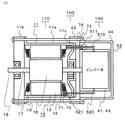
まず、図4、図5によりモータ100の全体構成を説明する。図4および図5において、回転電機としてのモータ100は、回転電機本体としてのモータ本体110と電力変換部140とを有する。モータ本体110は、収容部としてのモータケース11、ステータ12、ロータ16、回転シャフト17、出力軸18を有する。モータケース11は、軸方向に延びる筒状の筒状部11a、出力軸18側のブラケット11b、反出力軸側のブラケット11cを有する。ステータ12はステータコア13、インシュレータ14、固定子巻線15を有する。ロータ16は、円筒状の形状を有し、図示していないが円周方向にN極およびS極を交互に有し、その軸方向中心部を回転シャフト17が貫通している。回転シャフト17の図5における左方向端部が出力軸18とされている。ロータ16は、ステータコア13の内側に、ティース13aと径方向に対向するようにして、回転シャフト17を介してブラケット11b、11cにより回転可能に支持されている。電力変換部140は、モータ100の図5における右方、出力軸18と反対側に、モータ100と同軸に配設されている。
First, the overall configuration of the
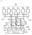
ステータコア13は、内径方向に突出するティース13aを有し、モータケース11の筒状部11a内に固定されている。ティース13aの端部により円筒状の内周部が形成されている。固定子巻線15は、それぞれ導体を途中で接続することなく連続した1本の導体で形成された巻線コイルとしての第1三相巻線70および同じく巻線コイルとしての第2三相巻線80を有する。第1三相巻線70は、図2に示されるように、引出線73、巻線U1+、渡り線771、巻線U1−、引出線71、引出線72、巻線V1+、渡り線772、巻線V1−、引出線75、引出線76、巻線W1+、渡り線773、巻線W1−、引出線74を有し、これらが連続した1本の導体で形成され、引出線74が巻き始め線とされ、引出線73が巻き終わり線とされたものである(図2において、巻き始めと巻き終わりの方向を矢印で示している、他の図においても同様である)。巻線U1+、巻線U1−、巻線V1+、巻線V1−、巻線W1+、巻線W1−は、インシュレータ14を介してステータコア13の内径方向に突出するティース13aに集中巻きで巻回されている(図4参照)。
The
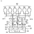
第2三相巻線80は、第1三相巻線70と区別するために符号を変えているが、第1三相巻線70と同様のものである。第2三相巻線80は、図3に示されるように、引出線83、巻線U2+、渡り線871、巻線U2−、引出線81、引出線82、巻線V2+、渡り線872、巻線V2−、引出線85、引出線86、巻線W2+、渡り線873、巻線W1−、引出線84を有し、これらが連続した1本の導体で形成され、引出線84が巻き始め線とされ、引出線83が巻き終わり線とされたものである。巻線U2+、線U2−、巻線V2+、巻線V2−、巻線W2+、巻線W2−は、インシュレータ14を介してステータコア13の内径方向に突出する別のティース13aに集中巻きで巻回されている(図4参照)。第1三相巻線70および第2三相巻線80の詳細については後で説明する。なお、詳細は省略するが、ステータコア13は互いに姿勢を変更可能に連結された12個のコア片が図4に示されるように円環状に配置されて構成されており、連結されたコア片を開いた状態で第1三相巻線70および第2三相巻線80を並行作業で、おのおの1本の導体で、各ティース13aに順次巻回した後、コア片を閉じて円環状にして図4に状態にされる。その後、中継線の接続作業が成される(後述)。
The second three-phase winding 80 has the same sign as the first three-phase winding 70, although the sign is changed to distinguish it from the first three-phase winding 70. As shown in FIG. 3, the second three-phase winding 80 includes a
電力変換部140は、第1インバータ41、第2インバータ42および円筒容器43を有する。円筒容器43は、円筒部44および蓋部45を有する。円筒部44は、図5における右方の端部が閉鎖された有底円筒状のものであり、円板状の蓋部45と組み合わされて円筒状の閉鎖された収容部を形成しており、モータケース11の右側方にモータケース11と同軸にして固定されている。円筒容器43に第1インバータ41および第2インバータ42が収容されている。第1インバータ41および第2インバータ42は、直流電源から入力される直流を三相交流に変換して後述の第1三相巻線70および第2三相巻線80に供給することによりステータ12に回転磁界が形成され、対向するロータ16が回転駆動される。
The
次に、第1三相巻線70、第2三相巻線80、第1インバータ41、第2インバータ42の詳細について図2〜図6により説明する。図2は第1三相巻線70の結線図、図3は第2三相巻線80の結線図、図6はインバータの結線図である。説明のために、図2に第1三相巻線70を、図3に第2三相巻線80を、分けて示しているが、実際は上述のように図2の第1三相巻線70および図3の第2三相巻線80が同じステータコア13の別のティース13aに巻回されている。なお、第2三相巻線80は第1三相巻線70と同様のものであり、第1三相巻線70に不具合が発生したときの後備のために設けられ、モータ100が用いられる車両の操舵の安全性を確保することを目的としている。
Next, details of the first three-phase winding 70, the second three-phase winding 80, the
図2において、第1三相巻線70は、三相分の巻線U1+、線U1−、巻線V1+、巻線V1−、巻線W1+、巻線W1−およびこれらを接続する渡り線771、渡り線771、渡り線773、引出線71、引出線72、引出線73、引出線74、引出線75、引出線76を有する。すなわち、引出線73、巻線U1+、渡り線771、巻線U1−、引出線71、引出線72、巻線V1+、渡り線772、巻線V1−、引出線75、引出線76、巻線W1+、渡り線773、巻線W1−、引出線74が連続した1本の導体で形成され直列に接続され、引出線74が巻き始め線とされ、引出線73が巻き終わり線とされ、第1三相巻線70を構成している。なお、図4および図5においては、渡り線771、渡り線771、渡り線773の図示を省略しているが、図5におけるモータケース11内のステータコア13の電力変換部140側に配設されている。
In FIG. 2, the first three-phase winding 70 includes a three-phase winding U1 +, a wire U1-, a winding V1 +, a winding V1-, a winding W1 +, a winding W1- and a connecting
引出線73は、巻線U1+の一端からステータ12の軸方向右方へ蓋部45を貫通して円筒容器43内まで延長されている(図2、図5)。引出線74は、巻線W1−の一端からステータ12の軸方向右方へ引出線73と並ぶようにして蓋部45を貫通して円筒容器43内まで延長されている。引出線73の端部と引出線74の端部と中継線510の一方の端部との3者が、円筒容器43内に位置する接続部511において溶接により固定され接続されている。中継線510の他方の端部は、後述の第1インバータ41のレグ51の接続部51c(図6参照)に溶接により接続されている。巻線U1−の一方の端部から延長された引出線71は、途中で接続されることなく引出線72を介してそのまま巻線V1+の他方の端部に連続している(図2参照)。また、図2、図4および図5に示されるように、中継線520が引出線71、72と後述の第1インバータ41のレグ52の接続部52cとの間に介挿されている。すなわち、中継線520は、引出線71と引出線72との境界部の接続部521において中継線520の一方の端部が溶接により接続されるとともに、接続部521からステータ12の軸方向右方へ蓋部45を貫通して円筒容器43の内部まで延在され、他方の端部がレグ52の接続部52c(図6)に接続されている。
The
巻線V1−の他方の端部から延長された引出線75は、途中で接続されることなく引出線76を介してそのまま巻線W1+の一方の端部に連続している。また、図2および図4に示されるように引出線75と引出線76との境界部の接続部531において中継線530が溶接により接続されている。中継線530は、接続部531からステータ12の軸方向右方へ蓋部45を貫通して円筒容器43の内部まで延在され(図5においては図示されていないが、中継線520と同様のものである)、後述の第1インバータ41の上アーム53aと下アーム53bとの接続部53c(図6)に接続されている。引出線71、引出線73、引出線74、引出線75は、インシュレータ14の突起部14aにひっかけて位置決めされている(図4参照)。なお、インシュレータ14に溝などを設けて這わすなどして位置決めしてもよい。
The
なお、接続部511、接続部521、接続部531における接続は、各2本、3本、2本の線(導体)が同じ箇所で接続されるのを模式的に図示したものであり、実際は引出線73と引出線74と中継線510とは3本まとめて溶接により接続される。引出線71と引出線72との境界部にある接続部521における中継線520の接続は、例えば中継線520の一方の端部を90度曲げ引出線71および引出線72の長さ方向に沿わせ、導体2本を溶接する形で溶接される。引出線75と引出線76との境界部における中継線530との溶接についても同様である。
In addition, the connection in the
第2三相巻線80についても第1三相巻線70と区別するために符号を変えているが第1三相巻線70と同様のものであり、巻線U2+、巻線U2−、巻線V2+、巻線V2−、巻線W2+、巻線W2−およびこれらを接続する渡り線871、渡り線872、渡り線873、引出線81、引出線82、引出線83、引出線84、引出線85、引出線86が、巻線U1+、巻線U1−、巻線V1+、巻線V1−、巻線W1+、巻線W1−およびこれらを接続する渡り線771、渡り線772、渡り線773、引出線71、引出線72、引出線73、引出線74、引出線75、引出線76に相当するものである。また、中継線540、中継線550、中継線560は中継線510、中継線520、中継線530に相当するものである。接続部541、接続部551、接続部561は、接続部511、接続部521、接続部531に相当するものである。なお、図4および図5においては、渡り線871、渡り線872、渡り線873の図示を省略しているが、図5におけるモータケース11内のステータコア13の電力変換部140側に配設されている。
The sign of the second three-phase winding 80 is also changed to distinguish it from the first three-phase winding 70, but is the same as the first three-phase winding 70, and the winding U2 +, the winding U2-, Winding V2 +, Winding V2-, Winding W2 +, Winding W2- and connecting
次に、第1インバータ41の詳細構成について図6により説明する。第1インバータ41は、U、V、W三相分のレグ51、52、53を有する。U相のレグ51は、上アーム51aと下アーム51bとが接続部51cにおいて直列に接続されるとともにコンデンサCが並列に接続されている。V相のレグ52は、上アーム52aと下アーム52bとが接続部52cにおいて直列に接続されるとともにコンデンサCが並列に接続されている。W相のレグ53は、上アーム53aと下アーム53bとが接続部53cにおいて直列に接続されるとともにコンデンサCが並列に接続されている。各レグ51、52、53の一端はリアクトル3を介して直流電源(バッテリ)2のプラス側に接続され、他端は接地されている。また、直流電源2のマイナス側は接地されている。レグ51、52、53の各上アームと下アームとの接続部51c、52c、53cに各々中継線510、520、530が接続されている。上および下の各アーム51a、51b、52a、52b、53a、53bはスイッチング素子としてのトランジスタとこれに並列に接続されたダイオードとを有する。第1インバータ41は、直流電源2から入力される直流を各アームのトランジスタのスイッチング動作により三相交流に変換して中継線510、520、530から出力する。
Next, a detailed configuration of the
図3における第2インバータ42は、図2における第1インバータ41と同様の構成であるが、両者を区別するために、符号を変えて図示している。すなわち、図3における第2インバータ42のレグ54、レグ55、レグ56は、図6におけるレグ51、レグ52、レグ53と同様のものである。また、第2インバータ42のその他の構成についても図2および図6の第1インバータ41と同様である。
The
なお、本発明において渡り線とは、離れたティース間を途中で導体を接続することなく連続に巻回して巻線を形成する際に各同一相の巻線間を接続するための配線をいうものとする。また、引出線とは、各ティースに巻回された巻線同士を接続するとともに巻線を電力変換部に接続するための配線をいうものとする。なお、この実施の形態においては、引出線は中継線を介して電力変換部(インバータ)に接続されているが、引出線をそのまま延長して電力変換部に接続してもよい。 In the present invention, the crossover wire refers to a wiring for connecting the windings of the same phase when windings are formed by continuously winding a distance between separated teeth without connecting a conductor. Shall. In addition, the lead wire refers to wiring for connecting the windings wound around each tooth and connecting the windings to the power conversion unit. In this embodiment, the lead line is connected to the power conversion unit (inverter) via the relay line, but the lead line may be extended as it is and connected to the power conversion unit.
モータ100は、前述のように(図2参照)、引出線71および引出線72は途中で接続されることなく、すなわち接続部を設けることなく巻線U1−と巻線V1+とを接続しており、引出線71と引出線72との境界部にある接続部521において中継線520と接続されるので、接続は実質的に2本の線を接続することに等しく、接続を簡素化できる。同様に、引出線75および引出線76は、途中で接続されることなく巻線V1−と巻線W1+とを接続しており、引出線75と引出線76との境界部にある接続部531において中継線530と接続されるので、接続は実質的に2本の線を接続することに等しく、接続を簡素化できる。
As described above (see FIG. 2), the
なお、上記では、引出線71および引出線72と中継線520との溶接、引出線75および引出線76と中継線530との溶接は、中継線520、530の端部をおよそ90度曲げて、その端部を引出線の長さ方向に沿わせて溶接するものを示したが、これに限らず、引出線71、72あるいは引出線75、76の境界部でU状に折りかえしてU状部を形成し、当該U状部を図5におけるステータ12の軸方向右方へ曲げて若干引出し、U状部と中継線520あるいは中継線530の一方の端部とを重ねて溶接するようにしてもよい。
In the above, the welding of the lead lines 71 and 72 and the
以上のように、この実施の形態においては、連続した引出線71と引出線72との境界部にある接続部521において中継線520と溶接されるので実質的に2本の線を溶接することになり、ばらばらの3本の線(引出線73、74および中継線510)がまとめて溶接される接続部511における溶接よりも溶接が容易でありかつ接続部(この実施の形態では、溶接によっている)が簡素化される。接続部531における溶接についても、接続部521における溶接と同様である。
As described above, in this embodiment, since the connecting
このため、1つの三相巻線において3本の線が溶接されるのは接続部511の1箇所であり、他の2箇所の接続部521、531は、実質的に2本の線が溶接されることになる。これにより、第1三相巻線70と第1インバータ41の各接続部52c、53cとの接続を簡素にすることができ、接続スペースが少ないモータを得ることができる。さらに、接続スペースが小さくできる分、第1三相巻線70とインバータ41との接続距離を短くすることができるので、抵抗損が低減され、モータ100の駆動性能を向上させる効果を有する。第2三相巻線80についても同様に構成され、同様の効果を奏する。
For this reason, three wires are welded in one three-phase winding at one place of the connecting
実施の形態2.
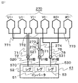
図7〜図9は、実施の形態2であるモータを示すものであり、図7は第1三相巻線の結線図、図8は第2三相巻線の結線図、図9はモータの断面図である。これらの図において、回転電機としてのモータ200は、回転電機本体としてのモータ本体210を有する(図9)。モータ本体210は、ステータ212を有する。ステータ212は、固定子巻線215を有する。固定子巻線215は、巻線コイルとしての第1三相巻線270および端部接続部279、並びに巻線コイルとしての第2三相巻線280および端部接続部289を有する。第1三相巻線270は、導体を途中で接続されることなく連続した1本の導体で形成され、巻線U1+の引出線273が巻き終わり線とされ、巻線W1−の引出線274が巻き始め線とされたものである。引出線273および引出線274は、インシュレータ14の突起部14a(図4参照)にひっかけることにより、固定もしくは位置決めされている。引出線273と引出線274とが、モータ本体210内の端部接続部279において溶接により接続されている(図7、図9参照)。また、端部接続部279を避けて引出線274の中間部に位置する接続部571において中継線570の一方の端部が溶接により接続されている。接続部571はステータコア13のインバータ41側に設けられている(図7、図9参照)。
7 to 9 show the motor according to the second embodiment. FIG. 7 is a connection diagram of the first three-phase winding, FIG. 8 is a connection diagram of the second three-phase winding, and FIG. 9 is a motor. FIG. In these drawings, a
中継線570の他方の端部は、電力変換部140のレグ51の上アーム51aと下アーム51bとの接続部51cに接続されている(図6、図7参照)。第2三相巻線280についても第1三相巻線270と区別するために符号を変えているだけで第1三相巻線270と同様のものであり、導体を途中で接続されることなく連続した1本の導体で形成され、巻線U2+の引出線283が巻き終わり線とされ、巻線W2−の引出線284が巻き始め線とされたものである。引出線283と引出線284とが、モータ本体210内の端部接続部289において溶接により接続されている(図9では図示されていない、図8参照)。また、引出線284の中間部にある接続部581において引出線284と中継線580の一方の端部とが溶接により接続されている(図8参照)。接続部581は、図示していないが、図9におけるモータケース11内であってステータコア13の電力変換部140側に設けられている。その他の構成については、実施の形態1と同様のものであるので、相当するものに同じ符号を付して説明を省略する。
The other end of the
なお、前記では引出線274を引出線273よりも長くして引出線274側において中継線570と接続する例(図7参照)を示したが、逆に引出線273を引出線274よりも長くして端部接続部を避けて引出線273側において中継線570と接続するようにしてもよい。また、巻線W1−に連続する引出線274を巻き始めとし、巻線U1+に連続する引出線273を巻き終わりとしたが、これに限られるものではなく、例えば引出線71と引出線72とを切断された形にし、巻線V1+に連続する引出線72を巻き始めとし、巻線U1−に連続する引出線71を巻き終わりとするように構成し、端部接続部279と同様の端部接続部を設けて両者を接続するとともに前記端部接続部を避けて引出線71あるいは引出線72に中継線520を接続する接続部を設けるようにしてもよい。この場合、引出線273と引出線274とは図7に示す端部接続部279を設けることを要せず連続した1本の導体で形成することができる。
In the above example, the
以上のようにこの実施の形態によれば、ばらばらの3本の導体を溶接する接続部をなくすことができる。実施の形態1よりも接続部の数は増えるが、ばらばらの3本の導体を溶接する接続部をなくすことにより、接続部が簡素化されるとともに接続の信頼性が向上する。また、大きなスペースを要するばらばらの3本の導体を溶接する接続部を、小さいスペースで済む2本接続部2箇所に変えることにより、スペースの有効活用ができ、設計の自由度を増やすことができる。 As described above, according to this embodiment, it is possible to eliminate the connection portion for welding the three separated conductors. Although the number of connection portions is increased as compared with the first embodiment, the connection portions are simplified and the connection reliability is improved by eliminating the connection portions for welding the three separated conductors. In addition, by changing the connection part that welds three separate conductors requiring a large space to two connection parts that require only a small space, the space can be used effectively and the degree of design freedom can be increased. .
実施の形態3.
図10〜図12は、実施の形態3であるモータを示すものであり、図10は第1三相巻線の結線図、図11は第2三相巻線の結線図、図12はモータの断面図である。この実施の形態においては、渡り線同士を接続する端部接続部を設けたものである。図10〜図12において、回転電機としてのモータ300は、回転電機本体としてのモータ本体310を有する(図12)。モータ本体310は、ステータ312を有する。ステータ312は、固定子巻線315を有する。固定子巻線315は、それぞれ導体を途中で接続することなく連続した1本の導体で形成された巻線コイルとしての第1三相巻線370および端部接続部379、並びに巻線コイルとしての第2三相巻線380および端部接続部389を有する。第1三相巻線370は、渡り線774、渡り線775を有する。この実施の形態においては、巻線U1+から延長された渡り線774が巻き終わり線とされ、巻線U1+と同じ相の巻線U1−から延長された渡り線775が巻き始め線とされ、渡り線774と渡り線775とがモータ本体310内の端部接続部379において溶接により接続されている(図10、図12参照)。
Embodiment 3 FIG.
10 to 12 show the motor according to the third embodiment. FIG. 10 is a connection diagram of the first three-phase winding, FIG. 11 is a connection diagram of the second three-phase winding, and FIG. FIG. In this embodiment, an end connection portion for connecting the crossover wires is provided. 10-12, the
第2三相巻線380についても、第1三相巻線370と同様の構成にされ、巻線U2+から延長された渡り線874が巻き終わり線とされ、巻線U2+と同じ相の巻線U2−から延長された渡り線875が巻き始め線とされ、渡り線874と渡り線875とがモータ本体310内の端部接続部389において溶接により接続されている(図12には示されていない、図11参照)。その他の構成については、実施の形態2と同様のものであるので、相当するものに同じ符号を付して説明を省略する。
The second three-phase winding 380 has the same configuration as that of the first three-phase winding 370, and the connecting
なお、前記では巻線U1−に連続する渡り線775を巻き始めとし、巻線U1+に連続する渡り線774を巻き終わりとするものを示したが、これに限られるものではなく、渡り線772を途中で切断された形にし、巻線V1−に連続する渡り線772を巻き始めとし、巻線V1+に連続する渡り線772を巻き終わりとし、前記巻き始めの渡り線772と巻き終わりの渡り線772とを端部接続部379と同様の形で接続するようにしてもよい。また、渡り線772の代わりに渡り線773を、巻き始めの渡り線773と巻き終わりの渡り線773とに分けて、同様の形で接続するようにしてもよい。第2三相巻線380は、第1三相巻線370と区別するために符号を変えているが、第1三相巻線370と同様のものであり、渡り線874、渡り線875が、第1三相巻線370の渡り線774、渡り線775にそれぞれ相当し、端部接続部389が端部接続部379に相当する。その他の構成については、実施の形態2と同様のものであるので、相当するものに同じ符号を付して説明を省略する。
In the above description, the winding
これにより、ばらばらの3本の導体を溶接する接続部がなくなり、接続の信頼性が向上し、また、大きなスペースが不要になる。さらに、巻始め部である渡り線775と巻終り部である渡り線774とを接続する端部接続部379が、接続部521、接続部571から離れた位置にあるので(図12参照)、作業性が向上し、接続作業が容易になる。第2三相巻線280についても同様である。
As a result, there is no connection part for welding the three separated conductors, connection reliability is improved, and a large space is not required. Furthermore, the
実施の形態4.
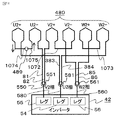
図13〜図17は、実施の形態4を示すものであり、図13はモータの第1三相巻線の結線図、図14はモータの第2三相巻線の結線図、図15はモータの断面図、図16はステータの結線構造を説明するためのステータの軸方向の一方側(出力軸18側)から見た平面模式図、図17は、ステータの結線構造を説明するためのステータの軸方向の他方側(電力変換部140側)から見た平面模式図である。回転電機としてのモータ400は、回転電機本体としてのモータ本体410を有する。モータ本体410は、ステータ412を有する。ステータ412は、固定子巻線415を有する。固定子巻線415は、巻線コイルとしての第1三相巻線470および端部接続部479、並びに巻線コイルとしての第2三相巻線480および端部接続部489を有する。
Embodiment 4 FIG.
FIGS. 13 to 17 show the fourth embodiment. FIG. 13 is a connection diagram of the first three-phase winding of the motor, FIG. 14 is a connection diagram of the second three-phase winding of the motor, and FIG. FIG. 16 is a cross-sectional view of the motor, FIG. 16 is a schematic plan view seen from one side (
第1三相巻線470は、それぞれ導体を途中で接続されることなく連続した1本の導体で形成され、巻き終わり線とされた渡り線974、巻き始め線とされた渡り線975、渡り線972、渡り線973を有し、渡り線974と渡り線975とは端部接続部479において溶接により接続されている(図13)。これらは図16に示されるようにモータケース11内であってステータコア13の左方(出力軸18)側に設けられている(図16参照、図15においては図示されていない)。
The first three-phase winding 470 is formed of a single continuous conductor without connecting the conductors in the middle, and the connecting
第2三相巻線480は、それぞれ導体を途中で接続されることなく連続した1本の導体で形成され、巻き終わり線とされた渡り線1074、巻き始め線とされた渡り線1075、渡り線1072、渡り線1073を有し、渡り線1074と渡り線1075とは端部接続部489において溶接により接続されている(図14)。これらは図15および図16に示されるようにモータケース11内のステータコア13の左方(出力軸18側)に設けられている。なお、図15および図17に示されるように、接続部571、接続部521、接続部531、接続部581、接続部551、接続部561はステータコア13の電力変換部140側に配置されている。
The second three-phase winding 480 is formed by one continuous conductor without connecting the conductors in the middle, and the connecting
なお、以上では端部接続部479をU相の(巻線U1+および巻線U1−)の渡り線974と渡り線975に設けた例を示した(図13)が、V相の渡り線972あるいはW相の渡り線973を分断された形にして巻き始め線および巻き終わり線とし、これら巻き始め線と巻き終わり線とを接続する端部接続部を設けるようにしてもよい。
In the above, an example in which the
以上のように、この実施の形態によれば端部接続部479、489がステータコア13の図15における左方に(図15では端部接続部479は図示されていない、図16参照)、接続部571、接続部521、接続部531、接続部581、接続部551、接続部561がステータコア13の電力変換部140側に、すなわちステータコア13を左右に挟んで配置されているので、モータ本体410の電力変換部140側のスペースを縮小できるとともに、第1三相巻線470および第2三相巻線480と電力変換部140との接続距離を短くできるので、抵抗損を低減させ、モータの駆動性能を向上させる効果を得ることができる。
As described above, according to this embodiment, the
なお、前記各実施の形態においては、引出線、渡り線、中継線の接続(接合)は、溶接により行うものを示したが、蝋付け、かしめその他の接合方法によるものであっても同様の効果を奏する。また、第1及び第2三相巻線は、それぞれ導体を途中で接続することなく連続した1本の導体で形成されたものを示したが、2本以上の導体が並列にされたもので形成されたものであっても、端部接続部を避けて中継線と接続するようにすれば、端部接続部を設けないで巻き始め線と巻き終わり線と中継線とを1箇所にまとめて接続する場合に比し、まとめて接続する導体の本数を削減できるので、同様の効果を奏する。 In each of the above embodiments, the connection (joining) of the lead wire, the crossover wire, and the relay wire is shown by welding, but the same is true even if it is made by brazing, caulking or other joining methods. There is an effect. The first and second three-phase windings are shown as being formed by one continuous conductor without connecting the conductors in the middle, but two or more conductors are arranged in parallel. Even if it is formed, if it is connected to the relay line while avoiding the end connection part, the winding start line, the winding end line and the relay line are gathered in one place without providing the end connection part. Since the number of conductors to be connected together can be reduced as compared with the case where they are connected to each other, the same effect can be obtained.
また、固定子巻線は、二個の三相巻線を有するものに限られず、一個あるいは三個以上の三相巻線を有するものであってもよい。さらに、三相巻線に限らず、二相巻線等であってもよい。前記各実施の形態に示したモータ本体と電力変換部とが一体化されたものにおいて、その作用効果が大きいが、一体化されたものに限定されるものではない。さらに、電動パワーステアリング装置に用いられるモータについて説明したが、他の用途のモータや発電機等の回転電機にも適用できる。回転電機が交流発電機の場合は、電力変換部として交流を直流に変換する交直変換器が用いられる。 Further, the stator winding is not limited to the one having two three-phase windings, and may be one or three or more three-phase windings. Furthermore, not only a three-phase winding but a two-phase winding may be used. In the case where the motor main body and the power conversion unit shown in each of the above embodiments are integrated, the effect is large, but the invention is not limited to the integration. Furthermore, although the motor used in the electric power steering apparatus has been described, the present invention can also be applied to rotating electric machines such as motors and generators for other uses. When the rotating electrical machine is an AC generator, an AC / DC converter that converts AC to DC is used as a power converter.
なお、本発明は、その発明の範囲内において、上述した各実施の形態を自由に組み合わせたり、各実施の形態を適宜、変更、省略したりすることが可能である。 In the present invention, the above-described embodiments can be freely combined within the scope of the invention, or each embodiment can be appropriately changed or omitted.
11 モータケース、12 ステータ、13 ステータコア、13a ティース、
15 固定子巻線、41,42 インバータ、
70,270,370,470 第1三相巻線、71,72,75,76 引出線、
80,280,380,480 第2三相巻線、81,82,85,86 引出線、
100,200,300,400 モータ、
110,210,310,410 モータ本体、140 電力変換部、
212,312,412 ステータ、215,315,415 固定子巻線、
273,274,283,284 引出線、
279,289,379,389,479,489 端部接続部、
520、530,550,560,570,580 中継線、
521,531,551,561,571,581 接続部、
774,775,874,875,974,975,1074,1075 渡り線、
U1+,U1− 巻線、U2+,U2− 巻線、V1+,V1− 巻線、
V2+,V2− 巻線、W1+、W1− 巻線、W2+,W2− 巻線。
11 Motor case, 12 Stator, 13 Stator core, 13a Teeth,
15 Stator winding, 41, 42 Inverter,
70, 270, 370, 470 First three-phase winding, 71, 72, 75, 76 Leader,
80, 280, 380, 480 Second three-phase winding, 81, 82, 85, 86 Leader,
100, 200, 300, 400 motor,
110, 210, 310, 410 motor body, 140 power conversion unit,
212, 312, 412 stator, 215, 315, 415 stator winding,
273, 274, 283, 284 Leader,
279, 289, 379, 389, 479, 489 end connection,
520, 530, 550, 560, 570, 580 trunk line,
521,531,551,561,571,581 connection part,
774,775,874,875,974,975,1074,1075 crossover,
U1 +, U1- winding, U2 +, U2- winding, V1 +, V1- winding,
V2 +, V2- winding, W1 +, W1- winding, W2 +, W2- winding.
Claims (8)
前記回転電機本体は、収容部と前記収容部に収容された固定子とを有し、
前記固定子は、ティースを有する固定子鉄心と巻線コイルとを有し、
前記巻線コイルは、連続した導体で形成されたものであって、巻き始め線と、前記ティースに集中巻きされた巻線と、前記巻線同士を接続する渡り線と、前記巻線に接続される引出線と、巻き終わり線とを有し、
前記巻線コイルは前記引出線を介して前記電力変換部に接続されるものである
回転電機。 A rotating electrical machine having a rotating electrical machine body and a power converter,
The rotating electrical machine main body has a housing part and a stator housed in the housing part,
The stator has a stator core having teeth and a winding coil,
The winding coil is formed of a continuous conductor, and is connected to the winding start wire, the winding concentratedly wound on the teeth, the connecting wire connecting the windings, and the winding. A leader line and a winding end line,
The rotating electrical machine, wherein the winding coil is connected to the power conversion unit via the lead wire.
請求項1に記載の回転電機。 The rotating electrical machine according to claim 1, wherein the rotating electrical machine main body and the power conversion unit are integrated.
前記中継線は、前記引出線と前記電力変換部との間に介挿され前記引出線と前記電力変換部とを接続するものである
請求項1または請求項2に記載の回転電機。 Having a trunk line,
The rotating electrical machine according to claim 1, wherein the relay line is inserted between the lead line and the power conversion unit and connects the lead line and the power conversion unit.
前記巻き始め線および前記巻き終わり線が、前記引出線とされたものであり、
前記端部接続部は、前記巻き始め線と前記巻き終わり線とを接続するものであり、
前記中継線が、前記端部接続部を避けて前記引出線に接続されるものである
請求項3に記載の回転電機。 Having an end connection,
The winding start line and the winding end line are the leader lines,
The end connection portion connects the winding start line and the winding end line,
The rotating electrical machine according to claim 3, wherein the relay wire is connected to the lead wire while avoiding the end connection portion.
前記引出線および端部接続部が、前記収容部内であって前記固定子鉄心の前記電力変換部側に設けられたものである
請求項4に記載の回転電機。 The power converter is disposed and integrated on one side in the axial direction of the rotating shaft of the rotating electrical machine body,
The rotating electrical machine according to claim 4, wherein the lead wire and the end connection portion are provided in the housing portion and on the power conversion portion side of the stator core.
前記巻き始め線および前記巻き終わり線が、前記渡り線とされたものであり、
前記端部接続部は、前記巻き始め線と前記巻き終わり線とを接続するものである
請求項1から請求項3のいずれか1項に記載の回転電機。 Having an end connection,
The winding start line and the winding end line are the crossover lines,
The rotating electrical machine according to any one of claims 1 to 3, wherein the end connection portion connects the winding start line and the winding end line.
前記渡り線および前記端部接続部が、前記収容部内であって前記固定子鉄心の前記電力変換部側と反対側に設けられたものである
請求項6に記載の回転電機。 The power converter is disposed and integrated on one side in the axial direction of the rotating shaft of the rotating electrical machine body,
The rotating electrical machine according to claim 6, wherein the connecting wire and the end connection portion are provided in the housing portion on the side opposite to the power conversion portion side of the stator core.
請求項1から請求項7のいずれか1項に記載の回転電機。 The rotating electrical machine according to any one of claims 1 to 7, wherein the rotating electrical machine body is used for assisting a steering force of a vehicle steering device.
Priority Applications (1)
| Application Number | Priority Date | Filing Date | Title |
|---|---|---|---|
| JP2016095023A JP2017204929A (en) | 2016-05-11 | 2016-05-11 | Rotary electric machine |
Applications Claiming Priority (1)
| Application Number | Priority Date | Filing Date | Title |
|---|---|---|---|
| JP2016095023A JP2017204929A (en) | 2016-05-11 | 2016-05-11 | Rotary electric machine |
Publications (1)
| Publication Number | Publication Date |
|---|---|
| JP2017204929A true JP2017204929A (en) | 2017-11-16 |
Family
ID=60322577
Family Applications (1)
| Application Number | Title | Priority Date | Filing Date |
|---|---|---|---|
| JP2016095023A Pending JP2017204929A (en) | 2016-05-11 | 2016-05-11 | Rotary electric machine |
Country Status (1)
| Country | Link |
|---|---|
| JP (1) | JP2017204929A (en) |
-
2016
- 2016-05-11 JP JP2016095023A patent/JP2017204929A/en active Pending
Similar Documents
| Publication | Publication Date | Title |
|---|---|---|
| CN105634225B (en) | Brushless DC motor and electric power steering system using the same | |
| JP5978357B2 (en) | Rotating electric machine | |
| JP5656436B2 (en) | Stator coils, rotating electrical machines and automobiles | |
| US20050242677A1 (en) | Electric motor, electric power steering apparatus equipped with the motor, and wire winding method for the motor | |
| JP5223259B2 (en) | motor | |
| US9705443B2 (en) | Motor, electric power steering device, and vehicle | |
| CN107846128B (en) | Brushless DC motor and electric power steering system using the same | |
| JP7124401B2 (en) | drive | |
| JP2010104112A (en) | Electric motor and electric power steering apparatus | |
| JP6058164B2 (en) | Rotating electric machine | |
| JP2011030406A (en) | Motor | |
| JP5930131B2 (en) | Electric motor control device, electric power steering device, and vehicle | |
| JP2013236455A (en) | Stator and motor | |
| JP6452889B2 (en) | Electric motor | |
| JP2005033924A (en) | Motor, and electric power steering device mounting the motor | |
| US20120098379A1 (en) | Brushless motor and electric power steering system | |
| JP2007215341A (en) | Stator of rotating electric machine for vehicle | |
| JP5125434B2 (en) | Motor and electric power steering device | |
| CN102142756B (en) | Motor | |
| JP5013165B2 (en) | Motor control device | |
| JP4052168B2 (en) | Wiring method between motor and power converter | |
| JP3812511B2 (en) | Motor coil feeding structure of hybrid drive unit | |
| JP3889305B2 (en) | Brushless motor and electric power steering apparatus equipped with a brushless motor | |
| JP2017204929A (en) | Rotary electric machine | |
| JP2012192787A (en) | Actuator and electric power steering device |