JP2017203585A - Cooling box - Google Patents
Cooling box Download PDFInfo
- Publication number
- JP2017203585A JP2017203585A JP2016095535A JP2016095535A JP2017203585A JP 2017203585 A JP2017203585 A JP 2017203585A JP 2016095535 A JP2016095535 A JP 2016095535A JP 2016095535 A JP2016095535 A JP 2016095535A JP 2017203585 A JP2017203585 A JP 2017203585A
- Authority
- JP
- Japan
- Prior art keywords
- cold storage
- heat transfer
- heat insulating
- cooling pipe
- pressing
- Prior art date
- Legal status (The legal status is an assumption and is not a legal conclusion. Google has not performed a legal analysis and makes no representation as to the accuracy of the status listed.)
- Pending
Links
- 238000001816 cooling Methods 0.000 title claims abstract description 26
- 238000003860 storage Methods 0.000 claims abstract description 63
- 239000011232 storage material Substances 0.000 claims abstract description 41
- 238000003825 pressing Methods 0.000 claims description 31
- 239000000463 material Substances 0.000 claims description 28
- 239000011347 resin Substances 0.000 claims description 17
- 229920005989 resin Polymers 0.000 claims description 17
- 238000005057 refrigeration Methods 0.000 claims description 8
- 125000006850 spacer group Chemical group 0.000 claims description 6
- JOYRKODLDBILNP-UHFFFAOYSA-N Ethyl urethane Chemical compound CCOC(N)=O JOYRKODLDBILNP-UHFFFAOYSA-N 0.000 claims description 3
- 239000006260 foam Substances 0.000 claims description 3
- 238000009413 insulation Methods 0.000 abstract description 9
- 239000011810 insulating material Substances 0.000 description 9
- XAGFODPZIPBFFR-UHFFFAOYSA-N aluminium Chemical compound [Al] XAGFODPZIPBFFR-UHFFFAOYSA-N 0.000 description 6
- 229910052782 aluminium Inorganic materials 0.000 description 6
- 238000010586 diagram Methods 0.000 description 4
- 239000004698 Polyethylene Substances 0.000 description 3
- 238000004519 manufacturing process Methods 0.000 description 3
- -1 polyethylene Polymers 0.000 description 3
- 229920000573 polyethylene Polymers 0.000 description 3
- 235000013305 food Nutrition 0.000 description 2
- 238000005338 heat storage Methods 0.000 description 2
- 238000010438 heat treatment Methods 0.000 description 2
- 239000003507 refrigerant Substances 0.000 description 2
- RYGMFSIKBFXOCR-UHFFFAOYSA-N Copper Chemical compound [Cu] RYGMFSIKBFXOCR-UHFFFAOYSA-N 0.000 description 1
- 238000010521 absorption reaction Methods 0.000 description 1
- NIXOWILDQLNWCW-UHFFFAOYSA-N acrylic acid group Chemical group C(C=C)(=O)O NIXOWILDQLNWCW-UHFFFAOYSA-N 0.000 description 1
- 229910052802 copper Inorganic materials 0.000 description 1
- 239000010949 copper Substances 0.000 description 1
- 239000011162 core material Substances 0.000 description 1
- 239000006185 dispersion Substances 0.000 description 1
- 238000009826 distribution Methods 0.000 description 1
- 238000005187 foaming Methods 0.000 description 1
- 238000007710 freezing Methods 0.000 description 1
- 230000008014 freezing Effects 0.000 description 1
- 239000003349 gelling agent Substances 0.000 description 1
- 230000005484 gravity Effects 0.000 description 1
- 239000005001 laminate film Substances 0.000 description 1
- 238000012986 modification Methods 0.000 description 1
- 230000004048 modification Effects 0.000 description 1
- 238000005192 partition Methods 0.000 description 1
- 239000004033 plastic Substances 0.000 description 1
- 229920003023 plastic Polymers 0.000 description 1
- 239000004800 polyvinyl chloride Substances 0.000 description 1
- 229920000915 polyvinyl chloride Polymers 0.000 description 1
- XLYOFNOQVPJJNP-UHFFFAOYSA-N water Substances O XLYOFNOQVPJJNP-UHFFFAOYSA-N 0.000 description 1
Images


Classifications
-
- F—MECHANICAL ENGINEERING; LIGHTING; HEATING; WEAPONS; BLASTING
- F25—REFRIGERATION OR COOLING; COMBINED HEATING AND REFRIGERATION SYSTEMS; HEAT PUMP SYSTEMS; MANUFACTURE OR STORAGE OF ICE; LIQUEFACTION SOLIDIFICATION OF GASES
- F25D—REFRIGERATORS; COLD ROOMS; ICE-BOXES; COOLING OR FREEZING APPARATUS NOT OTHERWISE PROVIDED FOR
- F25D11/00—Self-contained movable devices, e.g. domestic refrigerators
- F25D11/006—Self-contained movable devices, e.g. domestic refrigerators with cold storage accumulators
-
- F—MECHANICAL ENGINEERING; LIGHTING; HEATING; WEAPONS; BLASTING
- F25—REFRIGERATION OR COOLING; COMBINED HEATING AND REFRIGERATION SYSTEMS; HEAT PUMP SYSTEMS; MANUFACTURE OR STORAGE OF ICE; LIQUEFACTION SOLIDIFICATION OF GASES
- F25D—REFRIGERATORS; COLD ROOMS; ICE-BOXES; COOLING OR FREEZING APPARATUS NOT OTHERWISE PROVIDED FOR
- F25D16/00—Devices using a combination of a cooling mode associated with refrigerating machinery with a cooling mode not associated with refrigerating machinery
-
- F—MECHANICAL ENGINEERING; LIGHTING; HEATING; WEAPONS; BLASTING
- F25—REFRIGERATION OR COOLING; COMBINED HEATING AND REFRIGERATION SYSTEMS; HEAT PUMP SYSTEMS; MANUFACTURE OR STORAGE OF ICE; LIQUEFACTION SOLIDIFICATION OF GASES
- F25D—REFRIGERATORS; COLD ROOMS; ICE-BOXES; COOLING OR FREEZING APPARATUS NOT OTHERWISE PROVIDED FOR
- F25D19/00—Arrangement or mounting of refrigeration units with respect to devices or objects to be refrigerated, e.g. infrared detectors
- F25D19/003—Arrangement or mounting of refrigeration units with respect to devices or objects to be refrigerated, e.g. infrared detectors with respect to movable containers
-
- F—MECHANICAL ENGINEERING; LIGHTING; HEATING; WEAPONS; BLASTING
- F25—REFRIGERATION OR COOLING; COMBINED HEATING AND REFRIGERATION SYSTEMS; HEAT PUMP SYSTEMS; MANUFACTURE OR STORAGE OF ICE; LIQUEFACTION SOLIDIFICATION OF GASES
- F25D—REFRIGERATORS; COLD ROOMS; ICE-BOXES; COOLING OR FREEZING APPARATUS NOT OTHERWISE PROVIDED FOR
- F25D23/00—General constructional features
- F25D23/06—Walls
- F25D23/065—Details
-
- F—MECHANICAL ENGINEERING; LIGHTING; HEATING; WEAPONS; BLASTING
- F25—REFRIGERATION OR COOLING; COMBINED HEATING AND REFRIGERATION SYSTEMS; HEAT PUMP SYSTEMS; MANUFACTURE OR STORAGE OF ICE; LIQUEFACTION SOLIDIFICATION OF GASES
- F25D—REFRIGERATORS; COLD ROOMS; ICE-BOXES; COOLING OR FREEZING APPARATUS NOT OTHERWISE PROVIDED FOR
- F25D2201/00—Insulation
- F25D2201/10—Insulation with respect to heat
- F25D2201/12—Insulation with respect to heat using an insulating packing material
Abstract
Description
本発明は、庫内温度のバラツキを抑えることができる保冷庫に関する。 The present invention relates to a cool box that can suppress variations in the internal temperature.
従来、生鮮食品等、冷蔵や冷凍が必要な物品の輸送に用いられる保冷庫(保冷コンテナ)としては、保冷庫本体と、庫内を熱媒体により冷却する熱交換器と、この熱交換器から庫外の熱源機に亘り熱媒体を流動させる着脱自在な接続手段とを備えた可動式の保冷庫がある(特許文献1参照)。これによって、保冷庫内の収納スペースを広くすることができるとともに、軽量化を図ることができる。 Conventionally, as a cold storage (cold storage container) used for transporting goods that require refrigeration or freezing, such as fresh food, the cold storage main body, a heat exchanger that cools the interior with a heat medium, and the heat exchanger There is a movable cool box provided with detachable connection means for allowing a heat medium to flow over a heat source machine outside the refrigerator (see Patent Document 1). As a result, the storage space in the cool box can be widened and the weight can be reduced.
一方、特許文献2には、蓄冷剤及び冷凍機を備えた蓄冷型保冷庫が記載されている。 On the other hand, Patent Document 2 describes a cold storage type cool box equipped with a cold storage agent and a refrigerator.
ところで、保冷庫の内箱(伝熱板)裏面に蓄冷材を取り付け、内箱表面と庫内空気とを自然対流によって熱交換する構造の保冷庫は、蓄冷材の潜熱を利用することで長時間、庫内温度を低温に保つことが可能である。しかしながら、時間の経過とともに、外気との温度差の影響で庫内温度にバラツキ、例えば庫内の上部と下部との温度差が生じてしまう。 By the way, a cool storage with a structure that attaches a cold storage material to the back of the inner box (heat transfer plate) of the cold storage and exchanges heat between the inner box surface and the internal air by natural convection is long by using the latent heat of the cold storage material. It is possible to keep the temperature in the storage room at a low temperature. However, with the passage of time, the internal temperature varies due to the influence of the temperature difference from the outside air, for example, a temperature difference between the upper part and the lower part of the internal part occurs.
本発明は、上記に鑑みてなされたものであって、簡易に庫内温度のバラツキを抑えることができる保冷庫を提供することを目的とする。 This invention is made | formed in view of the above, Comprising: It aims at providing the cold storage which can suppress the dispersion | variation in the inside temperature easily.
上述した課題を解決し、目的を達成するために、本発明にかかる保冷庫は、断熱箱体によって囲まれた直方体の保冷室を庫内に形成した保冷庫であって、前記庫内の内面のうち、天面及び背面のみに蓄冷材を配置したことを特徴とする。 In order to solve the above-described problems and achieve the object, the cold storage according to the present invention is a cold storage in which a rectangular parallelepiped cold storage room surrounded by a heat insulating box is formed, and the inner surface of the storage Of these, the regenerator material is disposed only on the top surface and the back surface.
また、本発明にかかる保冷庫は、断熱箱体によって囲まれた直方体の保冷室を庫内に形成した保冷庫であって、一面が前記庫内側に露出して固定される伝熱板と、前記伝熱板に密着し、前記庫内を冷却する蓄冷材と、前記蓄冷材を冷却する冷却配管と、前記蓄冷材と前記冷却配管との間に配置され、前記蓄冷材と前記冷却配管とを熱的に接触させる伝熱シートと、前記冷却配管を前記庫内側に押圧する押圧平板と、前記押圧平板側が開口して前記伝熱板を固定する断熱部材と、を備え、前記断熱部材を金型として前記押圧平板の庫外側に充填した発泡樹脂材を発泡して前記押圧平板を庫内側に押圧し、前記伝熱シートを介して前記冷却配管を前記蓄冷材内に埋め込んだ蓄冷部を前記庫内の内面のうち、天面及び背面のみに配置したことを特徴とする。 Further, the cold storage according to the present invention is a cold storage in which a rectangular parallelepiped cold storage chamber surrounded by a heat insulating box is formed, and one surface is exposed and fixed inside the storage, and a heat transfer plate, The cool storage material that is in close contact with the heat transfer plate and cools the interior of the warehouse, the cooling pipe that cools the cool storage material, and the cool storage material and the cooling pipe are disposed between the cool storage material and the cooling pipe. A heat transfer sheet that thermally contacts the heat transfer sheet, a pressing flat plate that presses the cooling pipe to the inside of the warehouse, and a heat insulating member that opens on the pressing flat plate side and fixes the heat transfer plate. A cold storage part in which a foamed resin material filled on the outer side of the pressing plate as a mold is foamed to press the pressing plate to the inner side, and the cooling pipe is embedded in the cold storage material via the heat transfer sheet. Of the inner surface of the warehouse, it is arranged only on the top and back To.
また、本発明にかかる保冷庫は、断熱箱体によって囲まれた直方体の保冷室を庫内に形成した保冷庫であって、一面が前記庫内側に露出して固定される伝熱板と、前記伝熱板に密着し、伝熱袋で包装されて前記庫内を冷却する蓄冷材と、前記蓄冷材を冷却する冷却配管と、前記冷却配管を前記庫内側に押圧する押圧平板と、前記押圧平板側が開口して前記伝熱板を固定する断熱部材と、を備え、前記断熱部材を金型として前記押圧平板の庫外側に充填した発泡樹脂材を発泡して前記押圧平板を庫内側に押圧し、前記冷却配管を前記蓄冷材内に埋め込んだ蓄冷部を前記庫内の内面のうち、天面及び背面のみに配置したことを特徴とする。 Further, the cold storage according to the present invention is a cold storage in which a rectangular parallelepiped cold storage chamber surrounded by a heat insulating box is formed, and one surface is exposed and fixed inside the storage, and a heat transfer plate, A cold storage material that is in close contact with the heat transfer plate and is packed in a heat transfer bag to cool the inside of the warehouse, a cooling pipe that cools the cold storage material, a pressing flat plate that presses the cooling pipe to the inside of the warehouse, and And a heat insulating member that opens the pressing flat plate side and fixes the heat transfer plate, and foams a foamed resin material that fills the outer side of the pressing flat plate with the heat insulating member as a mold to bring the pressing flat plate to the inner side. The cool storage part which pressed and embedded the said cooling piping in the said cool storage material was arrange | positioned only in the top | upper surface and the back surface among the inner surfaces in the said store | warehouse | chamber.
また、本発明にかかる保冷庫は、上記の発明において、前記押圧平板と前記断熱部材との間に、硬質の断熱樹脂で形成されたスペーサを設けたことを特徴とする。 Moreover, the cool box according to the present invention is characterized in that, in the above invention, a spacer formed of a hard heat insulating resin is provided between the pressing flat plate and the heat insulating member.
また、本発明にかかる保冷庫は、上記の発明において、前記発泡樹脂材は発泡ウレタンであることを特徴とする。 Moreover, the cool box according to the present invention is characterized in that, in the above invention, the foamed resin material is foamed urethane.
また、本発明にかかる保冷庫は、上記の発明において、下部に冷凍ユニットを配置し、前記冷却配管は蒸発器配管であることを特徴とする。 Moreover, the cold storage according to the present invention is characterized in that, in the above-described invention, a refrigeration unit is disposed at a lower portion, and the cooling pipe is an evaporator pipe.
また、本発明にかかる保冷庫は、上記の発明において、前記天面に配置された蓄冷材の前記庫内側の表面積は、55%以上、80%未満であることを特徴とする。 Moreover, the cold storage according to the present invention is characterized in that, in the above-described invention, a surface area of the cold storage material arranged on the top surface is 55% or more and less than 80%.
本発明によれば、庫内の内面のうち、天面及び背面のみに蓄冷材を配置するのみで、庫内に一方向の循環流が生じるので、簡易に庫内温度のバラツキを抑えることができる。 According to the present invention, only the cold storage material is arranged only on the top surface and the back surface of the inner surface of the interior, and a unidirectional circulation flow is generated in the interior. it can.
以下、添付図面を参照してこの発明を実施するための形態について説明する。 DESCRIPTION OF EMBODIMENTS Hereinafter, embodiments for carrying out the present invention will be described with reference to the accompanying drawings.
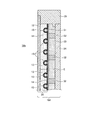
図1は、本発明の実施の形態に係る保冷庫10の外観構成を示す斜視図である。また、図2は、図1に示した背壁部16dの断面構成を示す図である。保冷庫10は、生鮮食品等、冷蔵や冷凍が必要な物品の輸送に用いられる保冷庫であり、庫内温度を一定に保持しつつ、トラック等による輸送が可能となっている。
FIG. 1 is a perspective view showing an external configuration of a
図1に示すように、保冷庫10は、冷凍機ユニット11上に保冷庫本体16が配置される。冷凍機ユニット11の下面四隅には、自在キャスター22が取り付けられており、保冷庫10を容易に移動させることができる。
As shown in FIG. 1, the
保冷庫本体16は、断熱箱体によって囲まれた直方体の保冷室16bを庫内に形成している。保冷室16bは、天壁部16c、背壁部16d、左右の側壁部16e,16e、及び底壁部16fによって画成されている。保冷室16bは、壁部が設けられていない前面開口16aが開閉扉18で開閉され、この前面開口16aから物品が出し入れされる。
The cool box
図2に示すように、背壁部16dには、庫外側(外側)から庫内側(内側)に向かって順に、断熱部材としての真空断熱材34、断熱機能を有する発泡樹脂33あるいは硬質の発砲樹脂であるスペーサ32、押圧平板31が配置される。押圧平板31の内側に蓄冷部20が配置される。
As shown in FIG. 2, the
蓄冷部20は、押圧平板31側で、伝熱シート14を介して蒸発器配管15が埋め込まれた蓄冷材13が配置される。さらに蓄冷材13の内側には、伝熱板12が蓄冷材13に密着して配置され、一面が保冷室16bに露出している。
In the
背壁部16dの端部には、伝熱板12と真空断熱材34とを固定する断熱部材35が配置される。
A
蒸発器配管15は、冷凍機ユニット11の冷凍回路に配管接続される。図示しない冷凍回路は、冷凍サイクルのうちの蒸発器以外のポンプ、凝縮器などを有するとともに、制御部を有する。制御部は、保冷室16b内に設けた図示しない温度センサが検出する温度をもとに、ポンプなどの冷凍回路を駆動して蓄冷材13を冷却する保冷制御を行う。
The
すなわち、蒸発器配管15内に冷却された冷媒が流れると、伝熱シート14を介して蓄冷材13が冷却される。そして、蓄冷材13は、伝熱板12を介して保冷室16bを冷却する。なお、蓄冷材13の外側は、断熱材で形成されているため、主として、蓄冷材13の吸熱は保冷室16b側に対して行われることになる。
That is, when the cooled refrigerant flows into the
なお、蓄冷部20は、天壁部16c、背壁部16d、左右の側壁部16e,16eの内側に設けられる。なお、蓄冷部20は、天壁部16c、背壁部16dのみに設けても良い。蓄冷部20は、天壁部16c、背壁部16d、左右の側壁部16e,16eの内の1以上の内側に設けてよい。なお、その他の底壁部16f、開閉扉18は、蓄冷部20の配置に替えて、真空断熱材を配置することが好ましい。
In addition, the
上述した伝熱板12は、例えばアルミニウムで形成される。蓄冷材13は、例えば、ポリエチレンの袋に水及びゲル化剤等を封入した公知のものを用いればよい。伝熱シート14は、例えば、アクリル系熱伝導シートである。蒸発器配管15は、例えば、銅管である。押圧平板31は、例えば、プラスチック板であり、具体的には硬質のポリ塩化ビニル板である。スペーサ32及び断熱部材35は、例えば、硬質の発泡ポリエチレンである。真空断熱材34は、例えば、芯材をラミネートフィルムによって被覆し、内部を真空状態に減圧して封止した公知のものを用いればよい。発泡樹脂33は、例えば、発泡ウレタンである。
The
[蓄冷部の製造]
ここで、図2及び図3を参照して蓄冷部20の製造について説明する。図3に示すように、まず、伝熱板12を断熱部材35に取り付ける。その後、伝熱板12の外側に蓄冷材13を密着配置する。さらに、蓄冷材13の外側を伝熱シート14で覆い、伝熱シート14の外側に蒸発器配管15を配置する。
[Manufacture of cold storage unit]
Here, manufacture of the
その後、蒸発器配管15の外側から押圧平板31を押圧して伝熱シート14とともに蒸発器配管15を蓄冷材13に食い込ませる。その後、押圧平板31の外側に複数のスペーサ32を介在させて、真空断熱材34を断熱部材35に取り付ける。
Thereafter, the
この状態では、図2に示すように、真空断熱材34と断熱部材35と押圧平板31とによって囲まれた閉空間領域Eが形成される。そして、閉空間領域Eに発泡樹脂33を充填する。発泡樹脂材33を加熱することによって発泡樹脂材33は膨張する。この膨張に伴って、発砲樹脂材33は、真空断熱材34と断熱部材35とが形成する凹部を金型として押圧平板31を内側に押圧する。すなわち、押圧平板31は、均一かつ大きな押圧力で蒸発器配管15をさらに内側に押圧し、蒸発器配管15を蓄冷材13内に埋め込む。この埋め込みに伴って、蓄冷材13及び伝熱シート14は、蒸発器配管15の外側にも食い込み、蒸発器配管15は、伝熱シート14を介した蓄冷材13との接触面積が大きくなるとともに、蒸発器配管15と蓄冷材13との間の空気を追い出す。
In this state, as shown in FIG. 2, a closed space region E surrounded by the vacuum
その後、発砲樹脂材33が固まることによって、蒸発器配管15と蓄冷材13との接触状態は維持される。
Thereafter, the foamed
本実施の形態では、蓄冷部20の製造に際し、アルミテープや両面テープを用いた密着作業を行うことがなく、容易に熱交換効率が高い蓄冷部20を製造することができる。また、蓄冷材13は、伝熱シート14を用いて蒸発器配管15と密着するので、アルミパック製でなくてもよく、例えばポリエチレン製の袋に収容された安価なものを用いることができる。
In the present embodiment, when the
[蓄冷部の変形例]
なお、上述した蓄冷材13に替えてアルミパック製の蓄冷材13を用いてもよい。図4に示すように、アルミパック製の蓄冷材13は、アルミパック自体が伝熱シート14に対応する伝熱シート44として機能する。したがって、アルミパック製の蓄冷材13を外側から直接、蒸発器配管15を押圧平板31によって押圧すればよい。
[Modification of cool storage unit]
In addition, it may replace with the
[蓄冷部の配置]
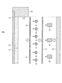
蓄冷部20は、庫内の内面のうち、天面及び背面のみに設けることが好ましい。図5に示すように、蓄冷部20は、天壁部16cの内面である天面、及び背壁部16dの内面である背面のみに設けられる。これによって、庫内で非対称の温度差が生じて循環流が生じる。図5では、前面側に上昇気流が生じ、天面側では、前面側から背面側への気流が生じ、背面側に下降気流が生じ、底面側では、背面側から前面側への気流が生じる。すなわち、一方向(図5上、時計回り方向)の循環流が生じる。これによって、庫内の空気は均一に拡散されて、庫内温度のバラツキを抑えることができる。
[Arrangement of cool storage unit]
It is preferable to provide the
なお、背面に替えて一方の側面に蓄熱部20を設けることも考えられる。しかし、この場合、開閉扉18側は外気の温度による影響が大きいにもかかわらず、天面、側面、底面、側面、天面の順に循環する循環流は、前面と背面との温度差を解消しづらく、天面、背面、底面、前面、天面の順に循環する循環流を発生させた方が庫内温度のバラツキを抑えることができる。
It is also conceivable to provide the
また、天面に配置された蓄冷材13の庫内側の表面積は、55%以上であることが好ましい。天面に配置される蓄冷材13の量は少ないにもかかわらず、天面に配置された蓄冷材13の表面積が55%未満で小さくなると、天面での冷却能力が落ち、一方向の循環流が生じにくくなり、庫内温度のバラツキが発生しやすくなるからである。
Moreover, it is preferable that the surface area inside the store | warehouse | chamber of the
一方、天面に配置された蓄冷材13の表面積が80%以上となると、天面における蓄冷材13の量が増えて冷却容量が大きくなり、保冷時間を長くすることができる。しかし、保冷庫10は、天面における蓄冷材13の量が大きいと、重心が鉛直上方に移動し、転倒しやすくなる。また、保冷庫10の運搬もしにくくなる。したがって、天面に配置された蓄冷材13の表面積が80%未満であることが好ましい。
On the other hand, when the surface area of the
上述した実施の形態において、GPSセンサや通信機能を設け、外部の管理サーバに接続して保冷庫10の流通管理、温度管理を行うようにしてもよい。
In the above-described embodiment, a GPS sensor and a communication function may be provided and connected to an external management server to perform distribution management and temperature management of the
また、保冷庫10は、蒸発器配管15を配置せず、蓄冷材13のみでもよい。すなわち、蓄冷材13は、蒸発器配管15と一体化しておらず、外部で冷却される交換可能なものであってもよい。
Further, the
さらに、冷凍機ユニット11は、保冷庫本体16と一体化せず、外部に設けてもよい。この場合、蓄冷材13の冷却時には、外部の冷凍機ユニットに配管接続され、外部の冷凍機ユニットから冷媒を循環させる。
Furthermore, the
また、保冷室16b内に保冷室16bを上下方向に区画する区画板を配置するための係止部やガイドを設けるようにしてもよい。
Moreover, you may make it provide the latching | locking part and guide for arrange | positioning the partition plate which divides the
なお、上述した実施の形態では、庫内を冷却する保冷庫を例に挙げたが、加熱を含めて庫内を一定温度状態に保つ蓄熱庫であってもよい。 In addition, in embodiment mentioned above, although the cold storage which cools the inside of a store | warehouse | chamber was mentioned as an example, the heat storage store | warehouse | chamber which keeps the inside of a store | warehouse in a constant temperature state including heating may be sufficient.
10 保冷庫
11 冷凍機ユニット
12 伝熱板
13 蓄冷材
14,44 伝熱シート
15 蒸発器配管
16 保冷庫本体
16a 前面開口
16b 保冷室
16c 天壁部
16d 背壁部
16e 側壁部
16f 底壁部
18 開閉扉
20 蓄冷部
22 自在キャスター
31 押圧平板
32 スペーサ
33 発泡樹脂
34 真空断熱材
35 断熱部材
DESCRIPTION OF
Claims (7)
前記庫内の内面のうち、天面及び背面のみに蓄冷材を配置したことを特徴とする保冷庫。 A cold storage room having a rectangular parallelepiped cold storage room surrounded by a heat insulating box,
A cold storage chamber in which the cold storage material is arranged only on the top surface and the back surface of the inner surface of the chamber.
一面が前記庫内側に露出して固定される伝熱板と、
前記伝熱板に密着し、前記庫内を冷却する蓄冷材と、
前記蓄冷材を冷却する冷却配管と、
前記蓄冷材と前記冷却配管との間に配置され、前記蓄冷材と前記冷却配管とを熱的に接触させる伝熱シートと、
前記冷却配管を前記庫内側に押圧する押圧平板と、
前記押圧平板側が開口して前記伝熱板を固定する断熱部材と、
を備え、
前記断熱部材を金型として前記押圧平板の庫外側に充填した発泡樹脂材を発泡して前記押圧平板を庫内側に押圧し、前記伝熱シートを介して前記冷却配管を前記蓄冷材内に埋め込んだ蓄冷部を前記庫内の内面のうち、天面及び背面のみに配置したことを特徴とする保冷庫。 A cold storage room having a rectangular parallelepiped cold storage room surrounded by a heat insulating box,
A heat transfer plate whose one surface is exposed and fixed to the inside of the storage;
A cold storage material that is in close contact with the heat transfer plate and cools the inside of the cabinet;
A cooling pipe for cooling the cold storage material;
A heat transfer sheet disposed between the regenerator material and the cooling pipe, wherein the regenerator material and the cooling pipe are in thermal contact;
A pressing flat plate for pressing the cooling pipe to the inside of the warehouse;
A heat insulating member for opening the pressing flat plate side and fixing the heat transfer plate;
With
Using the heat insulating member as a mold, the foamed resin material filled on the outer side of the pressing flat plate is foamed, the pressing flat plate is pressed on the inner side, and the cooling pipe is embedded in the cold storage material via the heat transfer sheet. The cool storage part characterized by having arrange | positioned the cool storage part only to the top | upper surface and the back surface among the inner surfaces in the said store | warehouse | chamber.
一面が前記庫内側に露出して固定される伝熱板と、
前記伝熱板に密着し、伝熱袋で包装されて前記庫内を冷却する蓄冷材と、
前記蓄冷材を冷却する冷却配管と、
前記冷却配管を前記庫内側に押圧する押圧平板と、
前記押圧平板側が開口して前記伝熱板を固定する断熱部材と、
を備え、
前記断熱部材を金型として前記押圧平板の庫外側に充填した発泡樹脂材を発泡して前記押圧平板を庫内側に押圧し、前記冷却配管を前記蓄冷材内に埋め込んだ蓄冷部を前記庫内の内面のうち、天面及び背面のみに配置したことを特徴とする保冷庫。 A cold storage room having a rectangular parallelepiped cold storage room surrounded by a heat insulating box,
A heat transfer plate whose one surface is exposed and fixed to the inside of the storage;
A cold storage material that is in close contact with the heat transfer plate and is packed in a heat transfer bag to cool the interior;
A cooling pipe for cooling the cold storage material;
A pressing flat plate for pressing the cooling pipe to the inside of the warehouse;
A heat insulating member for opening the pressing flat plate side and fixing the heat transfer plate;
With
Using the heat insulating member as a mold, the foamed resin material filled on the outside of the pressing plate is foamed, the pressing plate is pressed on the inside, and the cold storage part in which the cooling pipe is embedded in the cold storage material is inside the storage. Of the inner surface of the refrigeration, it is arranged only on the top surface and the back surface.
Priority Applications (2)
| Application Number | Priority Date | Filing Date | Title |
|---|---|---|---|
| JP2016095535A JP2017203585A (en) | 2016-05-11 | 2016-05-11 | Cooling box |
| CN201710316527.9A CN107367105A (en) | 2016-05-11 | 2017-05-08 | Freezer |
Applications Claiming Priority (1)
| Application Number | Priority Date | Filing Date | Title |
|---|---|---|---|
| JP2016095535A JP2017203585A (en) | 2016-05-11 | 2016-05-11 | Cooling box |
Publications (1)
| Publication Number | Publication Date |
|---|---|
| JP2017203585A true JP2017203585A (en) | 2017-11-16 |
Family
ID=60303791
Family Applications (1)
| Application Number | Title | Priority Date | Filing Date |
|---|---|---|---|
| JP2016095535A Pending JP2017203585A (en) | 2016-05-11 | 2016-05-11 | Cooling box |
Country Status (2)
| Country | Link |
|---|---|
| JP (1) | JP2017203585A (en) |
| CN (1) | CN107367105A (en) |
Cited By (1)
| Publication number | Priority date | Publication date | Assignee | Title |
|---|---|---|---|---|
| JP2022139570A (en) * | 2021-03-12 | 2022-09-26 | 株式会社イノアックコーポレーション | Heat-insulated container and warm-keeping box |
Families Citing this family (1)
| Publication number | Priority date | Publication date | Assignee | Title |
|---|---|---|---|---|
| JP2020037446A (en) * | 2018-09-06 | 2020-03-12 | パナソニックIpマネジメント株式会社 | Housing box |
Family Cites Families (10)
| Publication number | Priority date | Publication date | Assignee | Title |
|---|---|---|---|---|
| JP3957668B2 (en) * | 2003-09-05 | 2007-08-15 | シャープ株式会社 | Insulated box and refrigerator |
| JP2007240021A (en) * | 2006-03-06 | 2007-09-20 | Matsushita Electric Ind Co Ltd | Folding-type cool box |
| JP4602357B2 (en) * | 2007-01-10 | 2010-12-22 | シャープ株式会社 | Refrigerator insulation box and manufacturing method thereof |
| CN201047690Y (en) * | 2007-06-14 | 2008-04-16 | 河南新飞电器有限公司 | Cold-storage fridge |
| CN201421235Y (en) * | 2009-05-11 | 2010-03-10 | 刘怡然 | Refrigeration evaporating base of cold drink machine |
| JP2010276308A (en) * | 2009-05-29 | 2010-12-09 | Hitachi Appliances Inc | Refrigerator having vacuum heat insulating material |
| JP2013061131A (en) * | 2011-09-14 | 2013-04-04 | Hitachi Appliances Inc | Refrigerator having vacuum heat insulating material |
| WO2015025675A1 (en) * | 2013-08-22 | 2015-02-26 | 富士電機株式会社 | Cooler |
| JP2016003780A (en) * | 2014-06-13 | 2016-01-12 | 株式会社東芝 | refrigerator |
| CN104108539A (en) * | 2014-07-02 | 2014-10-22 | 国家农产品保鲜工程技术研究中心(天津) | Agricultural product storage and preservation test chamber |
-
2016
- 2016-05-11 JP JP2016095535A patent/JP2017203585A/en active Pending
-
2017
- 2017-05-08 CN CN201710316527.9A patent/CN107367105A/en active Pending
Cited By (1)
| Publication number | Priority date | Publication date | Assignee | Title |
|---|---|---|---|---|
| JP2022139570A (en) * | 2021-03-12 | 2022-09-26 | 株式会社イノアックコーポレーション | Heat-insulated container and warm-keeping box |
Also Published As
| Publication number | Publication date |
|---|---|
| CN107367105A (en) | 2017-11-21 |
Similar Documents
| Publication | Publication Date | Title |
|---|---|---|
| JP6107954B2 (en) | Cold storage | |
| US9624022B2 (en) | Storage container utilizing two different heat insulating materials in combination with a temperature control unit and a heat storage material placed within the container | |
| US8966932B2 (en) | Refrigerator | |
| US11340006B2 (en) | Storage container and refrigerator having the same | |
| KR20160097647A (en) | Refrigerator | |
| JP2012242072A (en) | Refrigerator | |
| US20200191451A1 (en) | Thermally Insulated Receptacle | |
| JP2017203585A (en) | Cooling box | |
| JP6407913B2 (en) | refrigerator | |
| JP2018091509A (en) | refrigerator | |
| JP2016090131A (en) | refrigerator | |
| JP2015175584A (en) | refrigerator | |
| JP2017203584A (en) | Cool box | |
| WO2015019686A1 (en) | Refrigeration storage unit | |
| JP2006189209A (en) | Cooling storage | |
| JP2014202394A (en) | Refrigerator | |
| JP6255698B2 (en) | Containment | |
| JP2016205778A (en) | refrigerator | |
| JP2005172306A (en) | Refrigerator | |
| US10739057B2 (en) | Refrigerator | |
| JP2020008254A (en) | refrigerator | |
| JP2000213851A (en) | Movable cold storage type cold reserving compartment | |
| JP6607745B2 (en) | refrigerator | |
| JP7209147B2 (en) | refrigerator | |
| JP2012242073A (en) | Refrigerator |