JP2017202320A - Walker apparatus and backrest for walker apparatus - Google Patents
Walker apparatus and backrest for walker apparatus Download PDFInfo
- Publication number
- JP2017202320A JP2017202320A JP2017093258A JP2017093258A JP2017202320A JP 2017202320 A JP2017202320 A JP 2017202320A JP 2017093258 A JP2017093258 A JP 2017093258A JP 2017093258 A JP2017093258 A JP 2017093258A JP 2017202320 A JP2017202320 A JP 2017202320A
- Authority
- JP
- Japan
- Prior art keywords
- backrest
- openings
- row
- strips
- extending
- Prior art date
- Legal status (The legal status is an assumption and is not a legal conclusion. Google has not performed a legal analysis and makes no representation as to the accuracy of the status listed.)
- Pending
Links
- 230000000712 assembly Effects 0.000 description 15
- 238000000429 assembly Methods 0.000 description 15
- 230000000149 penetrating effect Effects 0.000 description 6
- 238000004132 cross linking Methods 0.000 description 3
- 230000001771 impaired effect Effects 0.000 description 2
Images


Classifications
-
- A—HUMAN NECESSITIES
- A61—MEDICAL OR VETERINARY SCIENCE; HYGIENE
- A61H—PHYSICAL THERAPY APPARATUS, e.g. DEVICES FOR LOCATING OR STIMULATING REFLEX POINTS IN THE BODY; ARTIFICIAL RESPIRATION; MASSAGE; BATHING DEVICES FOR SPECIAL THERAPEUTIC OR HYGIENIC PURPOSES OR SPECIFIC PARTS OF THE BODY
- A61H3/00—Appliances for aiding patients or disabled persons to walk about
- A61H3/04—Wheeled walking aids for patients or disabled persons
-
- A—HUMAN NECESSITIES
- A61—MEDICAL OR VETERINARY SCIENCE; HYGIENE
- A61H—PHYSICAL THERAPY APPARATUS, e.g. DEVICES FOR LOCATING OR STIMULATING REFLEX POINTS IN THE BODY; ARTIFICIAL RESPIRATION; MASSAGE; BATHING DEVICES FOR SPECIAL THERAPEUTIC OR HYGIENIC PURPOSES OR SPECIFIC PARTS OF THE BODY
- A61H3/00—Appliances for aiding patients or disabled persons to walk about
- A61H2003/002—Appliances for aiding patients or disabled persons to walk about with attached or incorporated article carrying means
-
- A—HUMAN NECESSITIES
- A61—MEDICAL OR VETERINARY SCIENCE; HYGIENE
- A61H—PHYSICAL THERAPY APPARATUS, e.g. DEVICES FOR LOCATING OR STIMULATING REFLEX POINTS IN THE BODY; ARTIFICIAL RESPIRATION; MASSAGE; BATHING DEVICES FOR SPECIAL THERAPEUTIC OR HYGIENIC PURPOSES OR SPECIFIC PARTS OF THE BODY
- A61H3/00—Appliances for aiding patients or disabled persons to walk about
- A61H3/04—Wheeled walking aids for patients or disabled persons
- A61H2003/046—Wheeled walking aids for patients or disabled persons with braking means
-
- A—HUMAN NECESSITIES
- A61—MEDICAL OR VETERINARY SCIENCE; HYGIENE
- A61H—PHYSICAL THERAPY APPARATUS, e.g. DEVICES FOR LOCATING OR STIMULATING REFLEX POINTS IN THE BODY; ARTIFICIAL RESPIRATION; MASSAGE; BATHING DEVICES FOR SPECIAL THERAPEUTIC OR HYGIENIC PURPOSES OR SPECIFIC PARTS OF THE BODY
- A61H2201/00—Characteristics of apparatus not provided for in the preceding codes
- A61H2201/01—Constructive details
- A61H2201/0161—Size reducing arrangements when not in use, for stowing or transport
-
- A—HUMAN NECESSITIES
- A61—MEDICAL OR VETERINARY SCIENCE; HYGIENE
- A61H—PHYSICAL THERAPY APPARATUS, e.g. DEVICES FOR LOCATING OR STIMULATING REFLEX POINTS IN THE BODY; ARTIFICIAL RESPIRATION; MASSAGE; BATHING DEVICES FOR SPECIAL THERAPEUTIC OR HYGIENIC PURPOSES OR SPECIFIC PARTS OF THE BODY
- A61H2201/00—Characteristics of apparatus not provided for in the preceding codes
- A61H2201/01—Constructive details
- A61H2201/0192—Specific means for adjusting dimensions
-
- A—HUMAN NECESSITIES
- A61—MEDICAL OR VETERINARY SCIENCE; HYGIENE
- A61H—PHYSICAL THERAPY APPARATUS, e.g. DEVICES FOR LOCATING OR STIMULATING REFLEX POINTS IN THE BODY; ARTIFICIAL RESPIRATION; MASSAGE; BATHING DEVICES FOR SPECIAL THERAPEUTIC OR HYGIENIC PURPOSES OR SPECIFIC PARTS OF THE BODY
- A61H2201/00—Characteristics of apparatus not provided for in the preceding codes
- A61H2201/16—Physical interface with patient
- A61H2201/1602—Physical interface with patient kind of interface, e.g. head rest, knee support or lumbar support
- A61H2201/1623—Back
-
- A—HUMAN NECESSITIES
- A61—MEDICAL OR VETERINARY SCIENCE; HYGIENE
- A61H—PHYSICAL THERAPY APPARATUS, e.g. DEVICES FOR LOCATING OR STIMULATING REFLEX POINTS IN THE BODY; ARTIFICIAL RESPIRATION; MASSAGE; BATHING DEVICES FOR SPECIAL THERAPEUTIC OR HYGIENIC PURPOSES OR SPECIFIC PARTS OF THE BODY
- A61H2201/00—Characteristics of apparatus not provided for in the preceding codes
- A61H2201/16—Physical interface with patient
- A61H2201/1602—Physical interface with patient kind of interface, e.g. head rest, knee support or lumbar support
- A61H2201/1628—Pelvis
- A61H2201/1633—Seat
-
- A—HUMAN NECESSITIES
- A61—MEDICAL OR VETERINARY SCIENCE; HYGIENE
- A61H—PHYSICAL THERAPY APPARATUS, e.g. DEVICES FOR LOCATING OR STIMULATING REFLEX POINTS IN THE BODY; ARTIFICIAL RESPIRATION; MASSAGE; BATHING DEVICES FOR SPECIAL THERAPEUTIC OR HYGIENIC PURPOSES OR SPECIFIC PARTS OF THE BODY
- A61H2201/00—Characteristics of apparatus not provided for in the preceding codes
- A61H2201/16—Physical interface with patient
- A61H2201/1683—Surface of interface
- A61H2201/169—Physical characteristics of the surface, e.g. material, relief, texture or indicia
- A61H2201/1697—Breathability of the material
Landscapes
- Health & Medical Sciences (AREA)
- Epidemiology (AREA)
- Pain & Pain Management (AREA)
- Physical Education & Sports Medicine (AREA)
- Rehabilitation Therapy (AREA)
- Life Sciences & Earth Sciences (AREA)
- Animal Behavior & Ethology (AREA)
- General Health & Medical Sciences (AREA)
- Public Health (AREA)
- Veterinary Medicine (AREA)
- Rehabilitation Tools (AREA)
- Chair Legs, Seat Parts, And Backrests (AREA)
Abstract
Description
歩行器装置が提供される。特に、歩行器装置および歩行器装置用背もたれが提供される。 A walker device is provided. In particular, a walker device and a backrest for a walker device are provided.
特許文献1は、横方向に折り畳み可能な歩行器装置を開示している。歩行器装置は、離間された一対の直立フレーム部材を備える。歩行器装置は、直立フレーム部材に動作可能に連結される椅子を備える。歩行器装置は、フレーム部材から片持ちとされた背もたれを有する。背もたれは、離間された一対の上方および下方の架橋部材を備える。架橋部材は共通側端において一体に連結する。架橋部材同士は、互いに対して外向きに分岐している。使用者が直立フレーム部材を掴むときの背もたれ越しの使用者の視界を許容するために、架橋部材同士の間で開口部が背もたれを貫き広がる。 Patent document 1 is disclosing the walker apparatus which can be folded laterally. The walker apparatus includes a pair of upright frame members spaced apart. The walker device includes a chair that is operably coupled to the upright frame member. The walker apparatus has a backrest that is cantilevered from the frame member. The backrest includes a pair of spaced upper and lower bridging members. The bridging members are integrally connected at the common side end. The bridging members are branched outward with respect to each other. An opening extends through the backrest between the bridging members to allow the user visibility over the backrest when the user grasps the upright frame member.
一態様によれば、歩行器装置のための背もたれが提供される。背もたれは、弓形とされ、鉛直方向に延びる複数の貫通状の開口を有する。開口は、複数鉛直方向に延びて離間された列に配置され千鳥状とされる。 According to one aspect, a backrest for a walker device is provided. The backrest is arcuate and has a plurality of penetrating openings extending in the vertical direction. The openings are arranged in a plurality of rows extending in the vertical direction and spaced apart from each other, and have a staggered shape.
別の態様によれば、歩行器装置のための背もたれが提供される。背もたれは、弓形とされ、複数の開口であって、少なくとも一対の前記開口を備える開口の鉛直方向に延びる第1の列と、少なくとも1つの前記開口を備える開口の鉛直方向に延びる第2の列と、少なくとも一対の前記開口を備える開口の鉛直方向に延びる第3の列とを含む複数の開口を有する。第2の列は第1の列と第3の列との間にある。第1の列の開口は第3の列のそれぞれの開口と一列である。第2の列の開口は、第1の列の一対の前記開口の間で延び、前記第3の列の一対の前記開口の間で延びる。 According to another aspect, a backrest for a walker device is provided. The backrest is arcuate and has a plurality of openings, a first row extending in the vertical direction of the openings comprising at least a pair of the openings, and a second row extending in the vertical direction of the openings comprising at least one of the openings. And a third row including at least a pair of the openings and a third row extending in the vertical direction of the openings. The second column is between the first column and the third column. The openings in the first row are in line with the respective openings in the third row. The second row of openings extends between the pair of openings in the first row and extends between the pair of openings in the third row.
さらなる態様によれば、歩行器装置のための背もたれが提供される。背もたれは上方架橋部材および下方架橋部材を備える。背もたれは、架橋部材に結合され、架橋部材同士の間で延びる、水平方向で離間された鉛直方向の複数の条片を備える。背もたれは、鉛直方向の条片のうちの隣接する条片に結合され、鉛直方向の条片のうちの隣接する条片の間で延びる、鉛直方向で離間されて千鳥状とされた水平方向の複数の条片を備える。 According to a further aspect, a backrest for a walker device is provided. The backrest includes an upper bridging member and a lower bridging member. The backrest includes a plurality of horizontally spaced vertical strips coupled to the bridging members and extending between the bridging members. The backrest is coupled to adjacent strips of vertical strips and extends between adjacent strips of vertical strips, horizontally spaced in a staggered horizontal fashion A plurality of strips are provided.
本発明は、添付の図面を参照しつつ、例示のみを目的として提供されているその好ましい実施形態の以下の記載から、より簡単に理解されることになる。 The invention will be more readily understood from the following description of preferred embodiments thereof, given by way of example only, with reference to the accompanying drawings, in which:
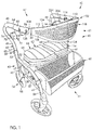
図面を参照し、最初に図1を参照すると、移動支援装置、この例では、第1の態様による歩行器装置40が、示されている。歩行器装置は、歩行器装置の後部47に隣接して離間された歩行器装置の側部43および45にそれぞれ位置付けられた、離間された一対の直立フレーム部材42および44を備えている。フレーム部材の各々は、フレーム部材42の下方端46および上方端48として示されている、下方端と、下方端から離間された上方端とを備えている。
Referring to the drawings, and initially referring to FIG. 1, a mobility assistance device, in this example a
フレーム部材42および44の各々は、この例では伸縮式となっており、複数の開口51が貫通状の内側管49と、内側管を受け入れるように成形された外側管53とを備えている。歩行器装置40は、伸縮式の管を選択的に調節して一体に固定するための調節機構59を有している。この例では、調節機構はつまみネジ63を備えている。つまみネジは、伸縮式の管49および53の高さを固定するように調節するために、開口51のうちの選択されたものに挿入できる。これは、図6に示した使用者65に最適な高さを提供するために、歩行器装置40の高さを調節することができる。
Each of the
図1に戻って参照すると、歩行器装置40は、少なくとも一部で弓形とされると共にこの例ではJ字形とされている一対の支持部材41および50を備えている。支持部材は、それぞれのフレーム部材に連結されている近位端と、近位端から離間された遠位端とを備えている。これは、フレーム部材42に結合された近位端52と、近位端から離間された遠位端54とを有する支持部材50によって示されている。各々の支持部材は、近位端から遠位端に向かって概して水平方向の様態で延びる細長い部分67を備えている。各々の支持部材50は、この例では、支持部材50の遠位端54から支持部材50の細長い部分へと延びる弓形の部分69を備えている。支持部材の近位端52は、この例では、フレーム部材の下方端46に隣接して下方端46から離間された場所において、フレーム部材に連結している。歩行器装置40は、この例では、それぞれのフレーム部材42の下方端46から延び、支持部材の遠位端54に隣接してそれぞれの支持部材50に連結している一対の棒材57を備えている。
Referring back to FIG. 1, the
歩行器装置40は、フレーム部材42および44の下方端と支持部材50の遠位端54とに回転可能に連結された複数の車輪組立体を備えている。これは、フレーム部材42の端46に回転可能に連結された車輪組立体56によって示されている。車輪組立体の各々は、地面と係合する車輪58を備えている。歩行器装置40は、この例では、可倒式バスケット60を備えている。図1に示しているように、バスケットは、選択的に、支持部材の遠位端54に隣接して、支持部材41および50に連結し、支持部材41と50との間で延びている。バスケット60は、この例では、歩行器装置の前部61に隣接して位置付けられている。歩行器装置40は、この例では枢動可能に一体に連結された2つの実質的に平面の部分66および68を有する椅子64を備える椅子組立体62をさらに備えている。椅子組立体の部分66および68は、それぞれの支持部材50および41の細長い部分67に枢動可能に連結している。したがって、椅子64は、直立フレーム部材42および44に動作可能に連結している。
The
図2で最も良好に見られるように、歩行器装置40は、折り畳み機構70を備えている。折り畳み機構は、この例では、ヒンジ83を介してヒンジで一体に連結され、それぞれの棒材57に枢動可能に連結してその棒材57から延びる2つの内側フレーム部材75および77から形成された内側フレーム組立体73を備えている。この例での折り畳み機構70は、椅子組立体62のそれぞれの部分66および68に枢動可能に連結してそれぞれの部分66および68から延びる一対の交差するリンク部材79および81を備えている。リンク部材79および81は、内側フレーム組立体73の内側フレーム部材75および77にもそれぞれ枢動可能に連結している。したがって、折り畳み機構70は、歩行器装置40の直立フレーム部材42および44に動作可能に連結し、直立フレーム部材42と44との間に置かれている。
As best seen in FIG. 2, the
折り畳み機構は、図3に示すように、フレーム部材42および44と支持部材41および50とを寄せ合うことで、歩行器装置を選択的に横方向に折り畳むことができるように構成される。したがって、折り畳み機構は、歩行器装置40を図3に示す折り畳み軸71の周りで横方向に折り畳み可能にすることができる。歩行器装置の折り畳み軸は、背もたれの折り畳み軸と称されてもよい。様々な部品および機能を含む歩行器装置用の折り畳み機構自体は、当業者には良く知られているため、折り畳み機構70はさらに詳細には説明しない。
As shown in FIG. 3, the folding mechanism is configured so that the walker device can be selectively folded in the lateral direction by bringing the
図1に戻って参照すると、歩行器装置40は、フレーム部材42および44のそれぞれの上方端48に連結してその上方端48から延びる一対のハンドルブレーキ組立体72および74を備えている。ハンドルブレーキ組立体72および74の各々はハンドル76を備えており、ハンドル76の作動は、車輪58のうちの少なくとも1つを選択的に制動させる。各々のハンドル76は、概して細長い環の形であり、使用者の手の一部を通して伸ばすことができる開口78を囲っている。
Referring back to FIG. 1, the
説明においてこの点に対して、歩行器装置は、例えば、Liuの米国特許第8,083,239号にさらに詳細に記載されている。様々な部品および機能を含む、伸縮式の管自体、車輪組立体自体、折り畳み機構自体、および、歩行者のためのブレーキ組立体自体の例は、当業者には知られているため、さらに詳細には説明しない。 In this regard, the walker apparatus is described in further detail in, for example, Liu US Pat. No. 8,083,239. Examples of the telescoping tube itself, the wheel assembly itself, the folding mechanism itself, and the brake assembly itself for pedestrians, including various parts and functions, are known to those skilled in the art and are therefore more detailed. Not explained.
図1に示すように、ハンドルブレーキ組立体の各々は、組立体72のための筐体82によって示されているように、それぞれのハンドル76が枢動可能に連結する筐体を有している。各々の筐体は、そのそれぞれのフレーム部材42の上方端48に動作可能に連結する近位端84と、その近位端から離間された遠位端86とを有している。
As shown in FIG. 1, each of the handle brake assemblies has a housing to which each handle 76 is pivotally connected, as shown by the
歩行器装置40は、この例では、フレーム部材42および44から延び、フレーム部材42および44から片持ちとされている背もたれ102を備えている。背もたれは、この例では可撓性であり、歩行器装置が図1で見られる展開モードであるとき、弓形である。一態様によれば、背もたれ102は、この例では上方架橋部材104および下方架橋部材106の離間された弓形の細長い一対の上方および下方の部分からなる。架橋部材同士は、この例では背もたれ102の近位端108および110のそれぞれの共通側端で一体に連結している。架橋部材104および106は、この例では歩行器装置40の前部61と側部43および45とに沿って概して水平方向に延びている。
The
背もたれ102は、上方架橋部材104における上部112と、下方架橋部材106における下部114とを有している。背もたれ102の上部および下部は、この例では略弓形となっている。背もたれ102は、凹状の内部116と凸状の外部118とを備えている。背もたれの内部および外部は、背もたれの上部112から下部114へと延びている。背もたれ102は、背もたれの近位端108および110にそれぞれ隣接する一対の開口を備えている。これは、背もたれの近位端108に隣接する開口128によって、図1で見られる。背もたれ102の端108および110は、この例では開口128を貫いて延びる、この例ではネジ130である連結具を介して、ハンドルブレーキ組立体72の筐体82の遠位端86に結合している。
The
上方架橋部材104は、フレーム部材42および44の上方端48から上向きに湾曲した様態で延びており、この場合には上向きに凸状の様態でそれぞれのフレーム部材から延びている。下方架橋部材106は、この例では下向きに湾曲した様態で延びており、この場合には下向きに凸状の様態で延びている。したがって、架橋部材104および106は、互いに対して外向きに分岐する方向でフレーム部材42および44から延びている。
The
背もたれ102は、歩行器装置40のフレーム部材42と44との間に位置付けられた中央領域134を有している。背もたれの中央領域は、背もたれの端108と110との間に位置付けられている。架橋部材104および106は、背もたれ102の近位端108および110から背もたれの中央領域134に向かってさらに外向きに延びるにつれて、さらに離されている。そのため、架橋部材104は、背もたれの端108および110から背もたれの中央領域に向かって互いに分岐している。図3で見られるように、架橋部材104は、歩行器装置40の折り畳み軸71と一列になる領域135で互いに対してさらに離間されている。歩行器装置の折り畳み軸は、背もたれの折り畳み軸と称されてもよい。
The
図4を参照すると、背もたれ102は、隣接する条片224、225、および226によって示されているように、この例では鉛直方向の条片で、鉛直方向に延びる離間された複数の細長い部材を備えている。条片は、架橋部材104と106とに連結し、架橋部材104と106との間で延びており、各々の条片は、上方架橋部材に連結された上方端と、下方架橋部材に連結している下方端とを有している。これは、図4において、上方架橋部材104に結合されている条片224の上方端229と、下方架橋部材106に結合している条片224の下方端231とによって見られる。条片224、225、および226は、この例では、形が矩形の角柱である。最も長い鉛直方向の条片は、この例では、背もたれ102の中央領域134に隣接している。鉛直方向の条片は、条片224、225、および226より短い背もたれの端108に隣接する条片227によって見られるように、この例では、背もたれの端108および110に隣接して最も短い。
Referring to FIG. 4, the
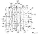
背もたれ102は、鉛直方向で離間されて千鳥状とされて水平方向に延びる複数の細長い部材を備えており、この例では、水平方向の条片が、隣接する列と対になる上下方向の列内で並べられ、上下方向において互いにずれている。これは、図5において、水平方向の条片253、255、および257の第1の列と、水平方向の条片259および261の第2の列と、水平方向の条片263、265、および267の第3の列によって見られる。水平方向の条片は、鉛直方向の条片225と226とに結合し、鉛直方向の条片225と226との間で延びている水平方向の条片259および261によって見られるように、隣接する鉛直方向の条片に結合し、隣接する鉛直方向の条片の間で延びている。各々の水平方向の条片は、第1の鉛直方向の条片に連結された第1の端と、第1の鉛直方向の条片に隣接して第2の鉛直方向の条片に連結された第2の端とを有している。これは、図5において、鉛直方向の条片225に結合された水平方向の条片261の第1の端269と、鉛直方向の条片226に結合された水平方向の条片261の第2の端271とによって見られる。
The
背もたれ102は、それを貫いて広がっており、鉛直方向に延びて離間された複数の列に配置され、鉛直方向に細長くされて千鳥状にされた複数の開口を有し、各々の列は一続きの前記開口を有している。これは、図5において、隣接する列228および230によって示されており、列228は開口232、234、236、および238を有しており、列230は開口240、242、および244を有している。
The
図4で見られるように、開口は、大部分について、この例では形が長円であり、架橋部材104と106との間に位置付けられている。図5を参照すると、鉛直方向に細長くされた開口は、鉛直方向の条片224および225に隣接する開口232、234、236、および238の列228によって見られるように、隣接する鉛直方向の条片の間にある。水平方向の条片は、水平方向の条片253と255との間に置かれる開口234、および、水平方向の条片255と257との間に置かれる開口236によって見られるように、それぞれの開口の間に置かれる。
As can be seen in FIG. 4, the opening is, for the most part, oval in this example and is positioned between bridging
列228の開口は、この例では列230の隣接する開口のそれぞれの中心点248から軸方向でずれている中心点246をそれぞれ有している。開口の偶数付けされた列が互いに一列になっており、開口の奇数付けされた列が互いに一列になっている。図4で見られるように、開口は、この例では、斜めに延びる並び250および252でさらに一列になっている。
The openings in
図5に戻って参照すると、各々の開口234の中心点246は、この例では列228の開口の第1の組のそれぞれの開口の中心点と鉛直方向で一列となり、開口の第2の組、つまり、図4で見られる斜めの並び250のそれぞれの開口の中心点と斜めで一列となり、開口の第3の組、つまり、斜めの並び252のそれぞれの開口の中心点と斜めで一列となる。図5を参照すると、1つおきの開口が、水平方向に延びる並び258における開口254、236、および256によって見られるように、この例でも水平方向に延びる並びで一列となっている。
Referring back to FIG. 5, the
図6を参照すると、背もたれ102の開口234によって、使用者が直立フレーム部材42および44を掴むとき、使用者65は背もたれ越しに見ることができる。これは、使用者の目139から、背もたれの開口を通じ、歩行器装置40の前における背もたれの下の地面143の領域141へと延びる視線137によって見られる。
Referring to FIG. 6, the
本明細書に記載された本発明の範囲内で多くの変更が可能であることは、理解されるものである。上記で提供された詳細の多くは、単なる例によるものであって、少なくとも以下の特許請求の範囲を参照して決定される本発明の範囲を限定するように意図されていないことは、当業者によってさらに理解されるものである。 It will be understood that many variations are possible within the scope of the invention described herein. It will be appreciated by those skilled in the art that many of the details provided above are by way of example only and are not intended to limit the scope of the invention as determined at least with reference to the following claims. Will be further understood.
歩行器装置が提供される。特に、歩行器装置および歩行器装置用背もたれが提供される。 A walker device is provided. In particular, a walker device and a backrest for a walker device are provided.
特許文献1は、横方向に折り畳み可能な歩行器装置を開示している。歩行器装置は、離間された一対の直立フレーム部材を備える。歩行器装置は、直立フレーム部材に動作可能に連結される椅子を備える。歩行器装置は、フレーム部材から片持ちとされた背もたれを有する。背もたれは、離間された一対の上方および下方の架橋部材を備える。架橋部材は共通側端において一体に連結する。架橋部材同士は、互いに対して外向きに分岐している。使用者が直立フレーム部材を掴むときの背もたれ越しの使用者の視界を許容するために、架橋部材同士の間で開口部が背もたれを貫き広がる。 Patent document 1 is disclosing the walker apparatus which can be folded laterally. The walker apparatus includes a pair of upright frame members spaced apart. The walker device includes a chair that is operably coupled to the upright frame member. The walker apparatus has a backrest that is cantilevered from the frame member. The backrest includes a pair of spaced upper and lower bridging members. The bridging members are integrally connected at the common side end. The bridging members are branched outward with respect to each other. An opening extends through the backrest between the bridging members to allow the user visibility over the backrest when the user grasps the upright frame member.
使用者が直立フレーム部材を掴むとき、背もたれによっては使用者の視界が害されうる。 When the user grasps the upright frame member, the user's field of view may be impaired depending on the backrest.
一態様によれば、歩行器装置のための背もたれが提供される。背もたれは、弓形とされ、鉛直方向に延びる複数の貫通状の開口を有する。開口は、複数鉛直方向に延びて離間された列に配置され千鳥状とされる。 According to one aspect, a backrest for a walker device is provided. The backrest is arcuate and has a plurality of penetrating openings extending in the vertical direction. The openings are arranged in a plurality of rows extending in the vertical direction and spaced apart from each other, and have a staggered shape.
別の態様によれば、歩行器装置のための背もたれが提供される。請求項1に記載の背もたれにおいて、各々の前記列は一続きの前記開口を有し、前記開口は、さらに、斜めに延びる並びで一列になる。 According to another aspect, a backrest for a walker device is provided. 2. The backrest according to claim 1, wherein each said row has a series of said openings, said openings further in a row extending diagonally.
また、別の態様よれば、歩行器装置のための背もたれが提供される。請求項1又は請求項2に記載の背もたれにおいて、複数の鉛直方向に延びる条片をさらに備え、前記鉛直方向に延びる開口は、隣接する前記条片の間にある。 According to another aspect, a backrest for a walker device is provided. The backrest according to
また、別の態様よれば、歩行器装置のための背もたれが提供される。請求項3に記載の背もたれにおいて、中央領域を有し、前記条片は、長さが異なり、前記中央領域に隣接して最も長い。 According to another aspect, a backrest for a walker device is provided. 4. The backrest according to claim 3, comprising a central region, wherein the strips are different in length and are the longest adjacent to the central region.
また、別の態様よれば、歩行器装置のための背もたれが提供される。請求項4に記載の背もたれにおいて、離間された一対の端を有し、前記中央領域は前記端同士の間にあり、前記条片は前記端に隣接して最も短い。 According to another aspect, a backrest for a walker device is provided. 5. The backrest according to claim 4, having a pair of spaced apart ends, the central region is between the ends, and the strip is shortest adjacent to the ends.
また、別の態様よれば、歩行器装置のための背もたれが提供される。請求項1に記載の背もたれにおいて、離間された一対の端と、前記端同士の間に中央領域とを有し、前記背もたれは、前記端において一体に結合される、離間された細長い一対の上方部および下方部を備え、前記背もたれの前記上方部および前記下方部は、前記端から前記中央領域に向かって互いに分岐する。 According to another aspect, a backrest for a walker device is provided. 2. The backrest according to claim 1 having a pair of spaced apart elongated ends having a pair of spaced apart ends and a central region between said ends, said backrest being joined together at said ends. An upper portion and a lower portion, and the upper portion and the lower portion of the backrest branch from each other toward the central region.
また、別の態様よれば、歩行器装置のための背もたれが提供される。請求項3から請求項5に記載の背もたれにおいて、前記条片は矩形の角柱であり、前記背もたれは一対の上方および下方の架橋部材をさらに備え、前記条片は、前記架橋部材同士を連結し、前記架橋部材同士の間で延びる。 According to another aspect, a backrest for a walker device is provided. 6. The backrest according to claim 3, wherein the strip is a rectangular prism, and the backrest further includes a pair of upper and lower bridging members, and the strip connects the bridging members to each other. , Extending between the bridging members.
また、別の態様よれば、歩行器装置のための背もたれが提供される。請求項1から請求項7に記載の背もたれにおいて、前記開口の偶数付けされた前記列が互いに一列になり、前記開口の奇数付けされた前記列が互いに一列になる。 According to another aspect, a backrest for a walker device is provided. The backrest according to any one of claims 1 to 7, wherein the even-numbered columns of the openings are aligned with each other, and the odd-numbered columns of the openings are aligned with each other.
また、別の態様よれば、歩行器装置のための背もたれが提供される。請求項1に記載の背もたれにおいて、前記開口の各々は中心点を有し、各々の前記開口の前記中心点は、前記開口の第1の組の中心点と鉛直方向で一列となり、前記開口の第2の組の中心点と斜めに一列となり、前記開口の第3の組の中心点と斜めに一列となる。 According to another aspect, a backrest for a walker device is provided. 2. The backrest according to claim 1, wherein each of the openings has a center point, and the center point of each of the openings is aligned with the center point of the first set of openings in a vertical direction, It is in a line obliquely with the center point of the second set and in a line obliquely with the center point of the third set of the openings.
別の態様によれば、歩行器装置のための背もたれが提供される。背もたれは、弓形とされ、複数の開口であって、少なくとも一対の前記開口を備える開口の鉛直方向に延びる第1の列と、少なくとも1つの前記開口を備える開口の鉛直方向に延びる第2の列と、少なくとも一対の前記開口を備える開口の鉛直方向に延びる第3の列とを含む複数の開口を有する。第2の列は第1の列と第3の列との間にある。第1の列の開口は第3の列のそれぞれの開口と一列である。第2の列の開口は、第1の列の一対の前記開口の間で延び、前記第3の列の一対の前記開口の間で延びる。 According to another aspect, a backrest for a walker device is provided. The backrest is arcuate and has a plurality of openings, a first row extending in the vertical direction of the openings comprising at least a pair of the openings, and a second row extending in the vertical direction of the openings comprising at least one of the openings. And a third row including at least a pair of the openings and a third row extending in the vertical direction of the openings. The second column is between the first column and the third column. The openings in the first row are in line with the respective openings in the third row. The second row of openings extends between the pair of openings in the first row and extends between the pair of openings in the third row.
また、別の態様よれば、歩行器装置のための背もたれが提供される。請求項1から請求項10に記載の背もたれにおいて、前記開口は輪郭が長円である。 According to another aspect, a backrest for a walker device is provided. The backrest according to any one of claims 1 to 10, wherein the opening has an oval outline.
さらなる態様によれば、歩行器装置のための背もたれが提供される。背もたれは上方架橋部材および下方架橋部材を備える。背もたれは、架橋部材に結合され、架橋部材同士の間で延びる、水平方向で離間された鉛直方向の複数の条片を備える。背もたれは、鉛直方向の条片のうちの隣接する条片に結合され、鉛直方向の条片のうちの隣接する条片の間で延びる、鉛直方向で離間されて千鳥状とされた水平方向の複数の条片を備える。 According to a further aspect, a backrest for a walker device is provided. The backrest includes an upper bridging member and a lower bridging member. The backrest includes a plurality of horizontally spaced vertical strips coupled to the bridging members and extending between the bridging members. The backrest is coupled to adjacent strips of vertical strips and extends between adjacent strips of vertical strips, horizontally spaced in a staggered horizontal fashion A plurality of strips are provided.
また、別の態様よれば、歩行器装置のための背もたれが提供される。請求項12に記載の背もたれにおいて、前記水平方向の条片は、隣接する列と対になる上下方向の列内で並べられ、上下方向において互いにずれる。 According to another aspect, a backrest for a walker device is provided. 13. The backrest according to claim 12, wherein the horizontal strips are arranged in a vertical row paired with an adjacent row and are shifted from each other in the vertical direction.
また、別の態様よれば、歩行器装置が提供される。請求項1から請求項13に記載の背もたれを備える歩行器装置。 According to another aspect, a walker device is provided. A walker device comprising the backrest according to claim 1.
また、別の態様よれば、歩行器装置が提供される。請求項14に記載の背もたれにおいて、離間された一対の直立部材をさらに備え、前記背もたれは、前記直立部材に片持ちとされる歩行器装置。 According to another aspect, a walker device is provided. The backrest according to claim 14, further comprising a pair of spaced upright members spaced apart from each other, wherein the backrest is cantilevered by the upright members.
背もたれの開口によって、使用者が直立フレーム部材を掴むとき、使用者は背もたれ越しに見ることができる。 The backrest opening allows the user to see over the backrest when the user grips the upright frame member.
本発明は、添付の図面を参照しつつ、例示のみを目的として提供されているその好ましい実施形態の以下の記載から、より簡単に理解されることになる。 The invention will be more readily understood from the following description of preferred embodiments thereof, given by way of example only, with reference to the accompanying drawings, in which:
図面を参照し、最初に図1を参照すると、移動支援装置、この例では、第1の態様による歩行器装置40が、示されている。歩行器装置は、歩行器装置の後部47に隣接して離間された歩行器装置の側部43および45にそれぞれ位置付けられた、離間された一対の直立フレーム部材42および44を備えている。フレーム部材の各々は、フレーム部材42の下方端46および上方端48として示されている、下方端と、下方端から離間された上方端とを備えている。
Referring to the drawings, and initially referring to FIG. 1, a mobility assistance device, in this example a
フレーム部材42および44の各々は、この例では伸縮式となっており、複数の開口51が貫通状の内側管49と、内側管を受け入れるように成形された外側管53とを備えている。歩行器装置40は、伸縮式の管を選択的に調節して一体に固定するための調節機構59を有している。この例では、調節機構はつまみネジ63を備えている。つまみネジは、伸縮式の管49および53の高さを固定するように調節するために、開口51のうちの選択されたものに挿入できる。これは、図6に示した使用者65に最適な高さを提供するために、歩行器装置40の高さを調節することができる。
Each of the
図1に戻って参照すると、歩行器装置40は、少なくとも一部で弓形とされると共にこの例ではJ字形とされている一対の支持部材41および50を備えている。支持部材は、それぞれのフレーム部材に連結されている近位端と、近位端から離間された遠位端とを備えている。これは、フレーム部材42に結合された近位端52と、近位端から離間された遠位端54とを有する支持部材50によって示されている。各々の支持部材は、近位端から遠位端に向かって概して水平方向の様態で延びる細長い部分67を備えている。各々の支持部材50は、この例では、支持部材50の遠位端54から支持部材50の細長い部分へと延びる弓形の部分69を備えている。支持部材の近位端52は、この例では、フレーム部材の下方端46に隣接して下方端46から離間された場所において、フレーム部材に連結している。歩行器装置40は、この例では、それぞれのフレーム部材42の下方端46から延び、支持部材の遠位端54に隣接してそれぞれの支持部材50に連結している一対の棒材57を備えている。
Referring back to FIG. 1, the
歩行器装置40は、フレーム部材42および44の下方端と支持部材50の遠位端54とに回転可能に連結された複数の車輪組立体を備えている。これは、フレーム部材42の端46に回転可能に連結された車輪組立体56によって示されている。車輪組立体の各々は、地面と係合する車輪58を備えている。歩行器装置40は、この例では、可倒式バスケット60を備えている。図1に示しているように、バスケットは、選択的に、支持部材の遠位端54に隣接して、支持部材41および50に連結し、支持部材41と50との間で延びている。バスケット60は、この例では、歩行器装置の前部61に隣接して位置付けられている。歩行器装置40は、この例では枢動可能に一体に連結された2つの実質的に平面の部分66および68を有する椅子64を備える椅子組立体62をさらに備えている。椅子組立体の部分66および68は、それぞれの支持部材50および41の細長い部分67に枢動可能に連結している。したがって、椅子64は、直立フレーム部材42および44に動作可能に連結している。
The
図2で最も良好に見られるように、歩行器装置40は、折り畳み機構70を備えている。折り畳み機構は、この例では、ヒンジ83を介してヒンジで一体に連結され、それぞれの棒材57に枢動可能に連結してその棒材57から延びる2つの内側フレーム部材75および77から形成された内側フレーム組立体73を備えている。この例での折り畳み機構70は、椅子組立体62のそれぞれの部分66および68に枢動可能に連結してそれぞれの部分66および68から延びる一対の交差するリンク部材79および81を備えている。リンク部材79および81は、内側フレーム組立体73の内側フレーム部材75および77にもそれぞれ枢動可能に連結している。したがって、折り畳み機構70は、歩行器装置40の直立フレーム部材42および44に動作可能に連結し、直立フレーム部材42と44との間に置かれている。
As best seen in FIG. 2, the
折り畳み機構は、図3に示すように、フレーム部材42および44と支持部材41および50とを寄せ合うことで、歩行器装置を選択的に横方向に折り畳むことができるように構成される。したがって、折り畳み機構は、歩行器装置40を図3に示す折り畳み軸71の周りで横方向に折り畳み可能にすることができる。歩行器装置の折り畳み軸は、背もたれの折り畳み軸と称されてもよい。様々な部品および機能を含む歩行器装置用の折り畳み機構自体は、当業者には良く知られているため、折り畳み機構70はさらに詳細には説明しない。
As shown in FIG. 3, the folding mechanism is configured so that the walker device can be selectively folded in the lateral direction by bringing the
図1に戻って参照すると、歩行器装置40は、フレーム部材42および44のそれぞれの上方端48に連結してその上方端48から延びる一対のハンドルブレーキ組立体72および74を備えている。ハンドルブレーキ組立体72および74の各々はハンドル76を備えており、ハンドル76の作動は、車輪58のうちの少なくとも1つを選択的に制動させる。各々のハンドル76は、概して細長い環の形であり、使用者の手の一部を通して伸ばすことができる開口78を囲っている。
Referring back to FIG. 1, the
説明においてこの点に対して、歩行器装置は、例えば、Liuへの米国特許第8,083,239号にさらに詳細に記載されている。様々な部品および機能を含む、伸縮式の管自体、車輪組立体自体、折り畳み機構自体、および、歩行者のためのブレーキ組立体自体の例は、当業者には知られているため、さらに詳細には説明しない。 In this regard, the walker device is described in more detail, for example, in US Pat. No. 8,083,239 to Liu. Examples of the telescoping tube itself, the wheel assembly itself, the folding mechanism itself, and the brake assembly itself for pedestrians, including various parts and functions, are known to those skilled in the art and are therefore more detailed. Not explained.
図1に示すように、ハンドルブレーキ組立体の各々は、組立体72のための筐体82によって示されているように、それぞれのハンドル76が枢動可能に連結する筐体を有している。各々の筐体は、そのそれぞれのフレーム部材42の上方端48に動作可能に連結する近位端84と、その近位端から離間された遠位端86とを有している。
As shown in FIG. 1, each of the handle brake assemblies has a housing to which each handle 76 is pivotally connected, as shown by the
歩行器装置40は、この例では、フレーム部材42および44から延び、フレーム部材42および44から片持ちとされている背もたれ102を備えている。背もたれは、この例では可撓性であり、歩行器装置が図1で見られる展開モードであるとき、弓形である。一態様によれば、背もたれ102は、この例では上方架橋部材104および下方架橋部材106の離間された弓形の細長い一対の上方および下方の部分からなる。架橋部材同士は、この例では背もたれ102の近位端108および110のそれぞれの共通側端で一体に連結している。架橋部材104および106は、この例では歩行器装置40の前部61と側部43および45とに沿って概して水平方向に延びている。
The
背もたれ102は、上方架橋部材104における上部112と、下方架橋部材106における下部114とを有している。背もたれ102の上部および下部は、この例では略弓形となっている。背もたれ102は、凹状の内部116と凸状の外部118とを備えている。背もたれの内部および外部は、背もたれの上部112から下部114へと延びている。背もたれ102は、背もたれの近位端108および110にそれぞれ隣接する一対の開口を備えている。これは、背もたれの近位端108に隣接する開口128によって、図1で見られる。背もたれ102の端108および110は、この例では開口128を貫いて延びる、この例ではネジ130である連結具を介して、ハンドルブレーキ組立体72の筐体82の遠位端86に結合している。
The
上方架橋部材104は、フレーム部材42および44の上方端48から上向きに湾曲した様態で延びており、この場合には上向きに凸状の様態でそれぞれのフレーム部材から延びている。下方架橋部材106は、この例では下向きに湾曲した様態で延びており、この場合には下向きに凸状の様態で延びている。したがって、架橋部材104および106は、互いに対して外向きに分岐する方向でフレーム部材42および44から延びている。
The
背もたれ102は、歩行器装置40のフレーム部材42と44との間に位置付けられた中央領域134を有している。背もたれの中央領域は、背もたれの端108と110との間に位置付けられている。架橋部材104および106は、背もたれ102の近位端108および110から背もたれの中央領域134に向かってさらに外向きに延びるにつれて、さらに離されている。そのため、架橋部材104は、背もたれの端108および110から背もたれの中央領域に向かって互いに分岐している。図3で見られるように、架橋部材104は、歩行器装置40の折り畳み軸71と一列になる領域135で互いに対してさらに離間されている。歩行器装置の折り畳み軸は、背もたれの折り畳み軸と称されてもよい。
The
図4を参照すると、背もたれ102は、隣接する条片224、225、および226によって示されているように、この例では鉛直方向の条片で、鉛直方向に延びる離間された複数の細長い部材を備えている。条片は、架橋部材104と106とに連結し、架橋部材104と106との間で延びており、各々の条片は、上方架橋部材に連結された上方端と、下方架橋部材に連結している下方端とを有している。これは、図4において、上方架橋部材104に結合されている条片224の上方端229と、下方架橋部材106に結合している条片224の下方端231とによって見られる。条片224、225、および226は、この例では、形が矩形の角柱である。最も長い鉛直方向の条片は、この例では、背もたれ102の中央領域134に隣接している。鉛直方向の条片は、条片224、225、および226より短い背もたれの端108に隣接する条片227によって見られるように、この例では、背もたれの端108および110に隣接して最も短い。
Referring to FIG. 4, the
背もたれ102は、鉛直方向で離間されて千鳥状とされて水平方向に延びる複数の細長い部材を備えており、この例では、水平方向の条片が、隣接する列と対になる上下方向の列内で並べられ、上下方向において互いにずれている。これは、図5において、水平方向の条片253、255、および257の第1の列と、水平方向の条片259および261の第2の列と、水平方向の条片263、265、および267の第3の列によって見られる。水平方向の条片は、鉛直方向の条片225と226とに結合し、鉛直方向の条片225と226との間で延びている水平方向の条片259および261によって見られるように、隣接する鉛直方向の条片に結合し、隣接する鉛直方向の条片の間で延びている。各々の水平方向の条片は、第1の鉛直方向の条片に連結された第1の端と、第1の鉛直方向の条片に隣接して第2の鉛直方向の条片に連結された第2の端とを有している。これは、図5において、鉛直方向の条片225に結合された水平方向の条片261の第1の端269と、鉛直方向の条片226に結合された水平方向の条片261の第2の端271とによって見られる。
The
背もたれ102は、それを貫いて広がっており、鉛直方向に延びて離間された複数の列に配置され、鉛直方向に細長くされて千鳥状にされた複数の開口を有し、各々の列は一続きの前記開口を有している。これは、図5において、隣接する列228および230によって示されており、列228は開口232、234、236、および238を有しており、列230は開口240、242、および244を有している。
The
図4で見られるように、開口は、大部分について、この例では形が長円であり、架橋部材104と106との間に位置付けられている。図5を参照すると、鉛直方向に細長くされた開口は、鉛直方向の条片224および225に隣接する開口232、234、236、および238の列228によって見られるように、隣接する鉛直方向の条片の間にある。水平方向の条片は、水平方向の条片253と255との間に置かれる開口234、および、水平方向の条片255と257との間に置かれる開口236によって見られるように、それぞれの開口の間に置かれる。
As can be seen in FIG. 4, the opening is, for the most part, oval in this example and is positioned between bridging
列228の開口は、この例では列230の隣接する開口のそれぞれの中心点248から軸方向でずれている中心点246をそれぞれ有している。開口の偶数付けされた列が互いに一列になっており、開口の奇数付けされた列が互いに一列になっている。図4で見られるように、開口は、この例では、斜めに延びる並び250および252でさらに一列になっている。
The openings in
図5に戻って参照すると、各々の開口234の中心点246は、この例では列228の開口の第1の組のそれぞれの開口の中心点と鉛直方向で一列となり、開口の第2の組、つまり、図4で見られる斜めの並び250のそれぞれの開口の中心点と斜めで一列となり、開口の第3の組、つまり、斜めの並び252のそれぞれの開口の中心点と斜めで一列となる。図5を参照すると、1つおきの開口が、水平方向に延びる並び258における開口254、236、および256によって見られるように、この例でも水平方向に延びる並びで一列となっている。
Referring back to FIG. 5, the
図6を参照すると、背もたれ102の開口234によって、使用者が直立フレーム部材42および44を掴むとき、使用者65は背もたれ越しに見ることができる。これは、使用者の目139から、背もたれの開口を通じ、歩行器装置40の前における背もたれの下の地面143の領域141へと延びる視線137によって見られる。
Referring to FIG. 6, the
本明細書に記載された本発明の範囲内で多くの変更が可能であることは、理解されるものである。上記で提供された詳細の多くは、単なる例によるものであって、少なくとも以下の特許請求の範囲を参照して決定される本発明の範囲を限定するように意図されていないことは、当業者によってさらに理解されるものである。
It will be understood that many variations are possible within the scope of the invention described herein. It will be appreciated by those skilled in the art that many of the details provided above are by way of example only and are not intended to limit the scope of the invention as determined at least with reference to the following claims. Will be further understood.
Claims (15)
上方架橋部材および下方架橋部材と、
前記架橋部材に結合され、前記架橋部材同士の間で延びる、水平方向に離間された鉛直方向の複数の条片と、
隣接する前記鉛直方向の条片に結合され、隣接する前記鉛直方向の条片の間で延びる、鉛直方向で離間されて千鳥状とされた水平方向の複数の条片と
を備える背もたれ。 A backrest for a walker device,
An upper bridging member and a lower bridging member;
A plurality of strips in a vertical direction that are coupled to the bridging member and extend between the bridging members and spaced apart in the horizontal direction;
A backrest comprising: a plurality of horizontal strips that are coupled to adjacent vertical strips and extend between adjacent vertical strips that are spaced apart in a vertical direction and are staggered.
Priority Applications (1)
| Application Number | Priority Date | Filing Date | Title |
|---|---|---|---|
| JP2019203860A JP6937816B2 (en) | 2016-05-09 | 2019-11-11 | Walker device |
Applications Claiming Priority (2)
| Application Number | Priority Date | Filing Date | Title |
|---|---|---|---|
| US15/149,611 US9744094B2 (en) | 2014-02-28 | 2016-05-09 | Walker apparatus and backrest therefor |
| US15/149611 | 2016-05-09 |
Related Child Applications (1)
| Application Number | Title | Priority Date | Filing Date |
|---|---|---|---|
| JP2019203860A Division JP6937816B2 (en) | 2016-05-09 | 2019-11-11 | Walker device |
Publications (1)
| Publication Number | Publication Date |
|---|---|
| JP2017202320A true JP2017202320A (en) | 2017-11-16 |
Family
ID=58672441
Family Applications (2)
| Application Number | Title | Priority Date | Filing Date |
|---|---|---|---|
| JP2017093258A Pending JP2017202320A (en) | 2016-05-09 | 2017-05-09 | Walker apparatus and backrest for walker apparatus |
| JP2019203860A Active JP6937816B2 (en) | 2016-05-09 | 2019-11-11 | Walker device |
Family Applications After (1)
| Application Number | Title | Priority Date | Filing Date |
|---|---|---|---|
| JP2019203860A Active JP6937816B2 (en) | 2016-05-09 | 2019-11-11 | Walker device |
Country Status (3)
| Country | Link |
|---|---|
| EP (1) | EP3243496A1 (en) |
| JP (2) | JP2017202320A (en) |
| CA (1) | CA2965806C (en) |
Cited By (1)
| Publication number | Priority date | Publication date | Assignee | Title |
|---|---|---|---|---|
| JP2021536345A (en) * | 2018-09-07 | 2021-12-27 | スタンダー インコーポレイテッドStander Inc. | Foldable walking device |
Citations (2)
| Publication number | Priority date | Publication date | Assignee | Title |
|---|---|---|---|---|
| JPH1191577A (en) * | 1997-09-26 | 1999-04-06 | Aprica Kassai Inc | Shopping cart |
| WO2007052734A1 (en) * | 2005-11-04 | 2007-05-10 | Okamura Corporation | Backrest device for chair |
Family Cites Families (8)
| Publication number | Priority date | Publication date | Assignee | Title |
|---|---|---|---|---|
| US5772234A (en) * | 1997-09-23 | 1998-06-30 | Luo; Chung-I | Configuring frame of walker |
| US5904398A (en) * | 1997-10-23 | 1999-05-18 | Farricielli; Susan | Ergonomically designed seat assembly for a portable wheelchair |
| USD587915S1 (en) * | 2005-10-20 | 2009-03-10 | Okamura Corporation | Chair |
| US8876209B2 (en) * | 2008-05-26 | 2014-11-04 | Steelcase Inc. | Conforming back for a seating unit |
| US8083239B2 (en) | 2008-10-08 | 2011-12-27 | Evolution Technologies Inc. | Foldable walker apparatus |
| US20120248740A1 (en) * | 2011-04-03 | 2012-10-04 | Osd Tech Llc | Decontamination Transport / Wheelchair |
| GB2499023A (en) * | 2012-02-03 | 2013-08-07 | Univ Sheffield | Collapsible wheelchair for accessing a toilet and shower |
| US9339432B2 (en) | 2014-02-28 | 2016-05-17 | Evolution Technologies Inc. | Walker apparatus and backrest therefor |
-
2017
- 2017-05-02 CA CA2965806A patent/CA2965806C/en active Active
- 2017-05-05 EP EP17169703.0A patent/EP3243496A1/en not_active Withdrawn
- 2017-05-09 JP JP2017093258A patent/JP2017202320A/en active Pending
-
2019
- 2019-11-11 JP JP2019203860A patent/JP6937816B2/en active Active
Patent Citations (2)
| Publication number | Priority date | Publication date | Assignee | Title |
|---|---|---|---|---|
| JPH1191577A (en) * | 1997-09-26 | 1999-04-06 | Aprica Kassai Inc | Shopping cart |
| WO2007052734A1 (en) * | 2005-11-04 | 2007-05-10 | Okamura Corporation | Backrest device for chair |
Cited By (1)
| Publication number | Priority date | Publication date | Assignee | Title |
|---|---|---|---|---|
| JP2021536345A (en) * | 2018-09-07 | 2021-12-27 | スタンダー インコーポレイテッドStander Inc. | Foldable walking device |
Also Published As
| Publication number | Publication date |
|---|---|
| JP2020022821A (en) | 2020-02-13 |
| CA2965806A1 (en) | 2017-11-09 |
| EP3243496A1 (en) | 2017-11-15 |
| CA2965806C (en) | 2019-09-17 |
| JP6937816B2 (en) | 2021-09-22 |
Similar Documents
| Publication | Publication Date | Title |
|---|---|---|
| JP6887006B2 (en) | Walker device and backrest for walker device | |
| US9744094B2 (en) | Walker apparatus and backrest therefor | |
| ES2765627T3 (en) | Walker | |
| JP2018529054A (en) | Brake assembly for walker device with adjustable height | |
| ES2871541T3 (en) | Foldable vehicle frame | |
| USD781021S1 (en) | Folding cart | |
| USD996536S1 (en) | Tubular exercise device | |
| JP6937816B2 (en) | Walker device | |
| US3366381A (en) | Collapsible hurdle | |
| SE536977C2 (en) | Motorized walker | |
| US7147242B2 (en) | Folding mechanism for a front wheel of a golf cart | |
| US4293144A (en) | Protective handrail for folding baby carriage | |
| US1625106A (en) | Folding back rest | |
| EP3064676A2 (en) | A tent frame and corresponding tent | |
| US1447486A (en) | Beach chair | |
| US351548A (en) | Speculum | |
| US2869949A (en) | Detachable safety guard for bathing table | |
| USD765565S1 (en) | Frame tubes of a folding motorized chair | |
| EP1160144A1 (en) | Improved shopping cart | |
| US1200556A (en) | Removable and collapsible top for vehicles. | |
| US20170295975A1 (en) | Sock holding dressing aid | |
| USD950426S1 (en) | Mobility assisting walker | |
| USD991300S1 (en) | Protective apparatus | |
| US336679A (en) | Henry williams | |
| US1863963A (en) | Fabric canopy support |
Legal Events
| Date | Code | Title | Description |
|---|---|---|---|
| A521 | Request for written amendment filed |
Free format text: JAPANESE INTERMEDIATE CODE: A523 Effective date: 20170718 |
|
| A621 | Written request for application examination |
Free format text: JAPANESE INTERMEDIATE CODE: A621 Effective date: 20170719 |
|
| A521 | Request for written amendment filed |
Free format text: JAPANESE INTERMEDIATE CODE: A523 Effective date: 20170725 |
|
| A977 | Report on retrieval |
Free format text: JAPANESE INTERMEDIATE CODE: A971007 Effective date: 20180531 |
|
| A131 | Notification of reasons for refusal |
Free format text: JAPANESE INTERMEDIATE CODE: A131 Effective date: 20180613 |
|
| A521 | Request for written amendment filed |
Free format text: JAPANESE INTERMEDIATE CODE: A523 Effective date: 20180823 |
|
| A131 | Notification of reasons for refusal |
Free format text: JAPANESE INTERMEDIATE CODE: A131 Effective date: 20181220 |
|
| A02 | Decision of refusal |
Free format text: JAPANESE INTERMEDIATE CODE: A02 Effective date: 20190730 |