JP2017201670A - Noise current absorber - Google Patents
Noise current absorber Download PDFInfo
- Publication number
- JP2017201670A JP2017201670A JP2016093474A JP2016093474A JP2017201670A JP 2017201670 A JP2017201670 A JP 2017201670A JP 2016093474 A JP2016093474 A JP 2016093474A JP 2016093474 A JP2016093474 A JP 2016093474A JP 2017201670 A JP2017201670 A JP 2017201670A
- Authority
- JP
- Japan
- Prior art keywords
- wall
- pair
- noise current
- housing portion
- current absorber
- Prior art date
- Legal status (The legal status is an assumption and is not a legal conclusion. Google has not performed a legal analysis and makes no representation as to the accuracy of the status listed.)
- Granted
Links
- 239000006096 absorbing agent Substances 0.000 title claims abstract description 61
- 238000006073 displacement reaction Methods 0.000 claims description 6
- 230000002093 peripheral effect Effects 0.000 claims description 5
- 239000000126 substance Substances 0.000 abstract 1
- 239000011347 resin Substances 0.000 description 69
- 229920005989 resin Polymers 0.000 description 69
- 239000000470 constituent Substances 0.000 description 8
- 230000000694 effects Effects 0.000 description 8
- 239000000428 dust Substances 0.000 description 5
- 238000010521 absorption reaction Methods 0.000 description 2
- 238000003780 insertion Methods 0.000 description 2
- 230000037431 insertion Effects 0.000 description 2
- 238000000034 method Methods 0.000 description 2
- 238000000465 moulding Methods 0.000 description 2
- 230000000149 penetrating effect Effects 0.000 description 2
- 238000005452 bending Methods 0.000 description 1
- 230000005484 gravity Effects 0.000 description 1
- 238000004519 manufacturing process Methods 0.000 description 1
- 239000002184 metal Substances 0.000 description 1
- 238000012986 modification Methods 0.000 description 1
- 230000004048 modification Effects 0.000 description 1
- 239000013589 supplement Substances 0.000 description 1
Images

Classifications
-
- H—ELECTRICITY
- H05—ELECTRIC TECHNIQUES NOT OTHERWISE PROVIDED FOR
- H05K—PRINTED CIRCUITS; CASINGS OR CONSTRUCTIONAL DETAILS OF ELECTRIC APPARATUS; MANUFACTURE OF ASSEMBLAGES OF ELECTRICAL COMPONENTS
- H05K9/00—Screening of apparatus or components against electric or magnetic fields
- H05K9/0073—Shielding materials
- H05K9/0098—Shielding materials for shielding electrical cables
-
- H—ELECTRICITY
- H01—ELECTRIC ELEMENTS
- H01F—MAGNETS; INDUCTANCES; TRANSFORMERS; SELECTION OF MATERIALS FOR THEIR MAGNETIC PROPERTIES
- H01F17/00—Fixed inductances of the signal type
- H01F17/04—Fixed inductances of the signal type with magnetic core
- H01F17/06—Fixed inductances of the signal type with magnetic core with core substantially closed in itself, e.g. toroid
-
- H—ELECTRICITY
- H01—ELECTRIC ELEMENTS
- H01F—MAGNETS; INDUCTANCES; TRANSFORMERS; SELECTION OF MATERIALS FOR THEIR MAGNETIC PROPERTIES
- H01F27/00—Details of transformers or inductances, in general
- H01F27/02—Casings
-
- H—ELECTRICITY
- H05—ELECTRIC TECHNIQUES NOT OTHERWISE PROVIDED FOR
- H05K—PRINTED CIRCUITS; CASINGS OR CONSTRUCTIONAL DETAILS OF ELECTRIC APPARATUS; MANUFACTURE OF ASSEMBLAGES OF ELECTRICAL COMPONENTS
- H05K9/00—Screening of apparatus or components against electric or magnetic fields
- H05K9/0007—Casings
-
- H—ELECTRICITY
- H05—ELECTRIC TECHNIQUES NOT OTHERWISE PROVIDED FOR
- H05K—PRINTED CIRCUITS; CASINGS OR CONSTRUCTIONAL DETAILS OF ELECTRIC APPARATUS; MANUFACTURE OF ASSEMBLAGES OF ELECTRICAL COMPONENTS
- H05K9/00—Screening of apparatus or components against electric or magnetic fields
- H05K9/0073—Shielding materials
- H05K9/0075—Magnetic shielding materials
-
- H—ELECTRICITY
- H01—ELECTRIC ELEMENTS
- H01F—MAGNETS; INDUCTANCES; TRANSFORMERS; SELECTION OF MATERIALS FOR THEIR MAGNETIC PROPERTIES
- H01F17/00—Fixed inductances of the signal type
- H01F17/04—Fixed inductances of the signal type with magnetic core
- H01F17/06—Fixed inductances of the signal type with magnetic core with core substantially closed in itself, e.g. toroid
- H01F2017/065—Core mounted around conductor to absorb noise, e.g. EMI filter
Abstract
Description
本開示は、電線に取り付けられて当該電線を流れる雑音電流を吸収する雑音電流吸収具に関する。 The present disclosure relates to a noise current absorber that is attached to an electric wire and absorbs a noise current flowing through the electric wire.
従来、電線に取り付けられて当該電線を流れる雑音電流を吸収する雑音電流吸収具が知られている。この種の雑音電流吸収具の一つとして、互いに当接させると全体として筒状又は環状(以下、両形状のことを筒状と総称する。)になる一対の磁性体と、これらの磁性体が筒状とされた状態で両磁性体を保持可能な一対の収容部とを備えるものがある。一対の収容部の構成としては、例えば、特許文献1に開示されているように、それぞれが凹部を有し、当該各凹部には、前記一対の磁性体のそれぞれを収容可能な形状が考えられる。このような一対の収容部は、前記各凹部に前記各磁性体が収容された状態で前記凹部同士を互いに突合せた閉鎖時には、前記一対の磁性体が筒状になるように構成される。また、一対の収容部に少なくとも計2対設けられた係合部と被係合部とを前記閉鎖時に係合させることにより、前記一対の収容部は、前記閉鎖状態が維持され、前記一対の磁性体は筒状になった閉鎖状態が維持される。
Conventionally, a noise current absorber that is attached to an electric wire and absorbs a noise current flowing through the electric wire is known. As one of the noise current absorbers of this type, a pair of magnetic bodies that are cylindrical or annular as a whole when contacted with each other (hereinafter, both shapes are collectively referred to as a cylindrical shape), and these magnetic bodies Some have a pair of accommodating portions capable of holding both magnetic bodies in a cylindrical shape. As a configuration of the pair of housing portions, for example, as disclosed in
このような構造の雑音電流吸収具を電線に対して取り付けると、筒状になる一対の磁性体が電線を外周側から取り囲み、これにより、一対の磁性体が磁気的に閉磁路を形成して、所期の雑音電流吸収能が発揮されることになる。 When a noise current absorber having such a structure is attached to an electric wire, a pair of cylindrical magnetic bodies surrounds the electric wire from the outer peripheral side, whereby the pair of magnetic bodies magnetically form a closed magnetic circuit. The expected noise current absorption capability will be exhibited.
しかしながら、このような雑音電流吸収具は、シャーシ等の装着対象に装着して使用されることがあり、その場合、ネジを用いて装着対象に装着されることがある。ネジを用いた装着方法としては、例えば特開平2−91903号公報等に記載のように、雑音電流吸収具自体にネジを挿入可能なネジ穴を設けたり、ネジを挿入可能なネジ穴を両端に有する帯状部材を当該雑音電流吸収具を挟んで装着対象に固定したりする方法が考えられる。それらの場合、前記ネジの回転に応じて、前記一対の収容部が相対的にずれるように力が加わることがあった。 However, such a noise current absorber may be used by being mounted on a mounting target such as a chassis, and in that case, it may be mounted on the mounting target using a screw. As a mounting method using a screw, for example, as described in JP-A-2-91903, a screw hole into which a screw can be inserted is provided in the noise current absorber itself, or a screw hole into which a screw can be inserted is provided at both ends. A method of fixing the belt-shaped member included in the mounting object to the mounting target with the noise current absorber interposed therebetween is conceivable. In those cases, a force may be applied so that the pair of accommodating portions are relatively displaced in accordance with the rotation of the screw.
以上のような事情から、互いに当接させると筒状になる一対の磁性体を一対の収容部にそれぞれ収容した雑音電流吸収具では、閉鎖状態に維持された一対の収容部がネジを用いて装着対象に装着される際に、一対の収容部がずれるのを抑制できることが望ましい。 From the above circumstances, in the noise current absorber in which a pair of magnetic bodies that are cylindrical when brought into contact with each other are accommodated in a pair of accommodating portions, the pair of accommodating portions that are maintained in a closed state use screws. It is desirable to be able to prevent the pair of storage portions from being displaced when being mounted on the mounting target.
以下に説明する雑音電流吸収具は、互いに当接させると全体として筒状又は環状になる一対の磁性体と、それぞれが凹部を有し、当該各凹部には、前記一対の磁性体のそれぞれを収容可能で、前記各凹部に前記各磁性体が収容された状態で前記凹部同士を互いに突合せた閉鎖時には、前記一対の磁性体が筒状又は環状になる一対の収容部と、前記一対の収容部のそれぞれに、前記一対の磁性体の前記筒又は環の中心を挟んでそれぞれ設けられ、前記閉鎖時に互いに係合することで、前記一対の磁性体が筒状又は環状になった閉鎖状態を維持可能な係合部及び被係合部と、少なくとも一方の前記収容部における他方の前記収
容部との突合せ面に隣接して、前記少なくとも一方の収容部に一体成形され、前記他方の収容部が突き合わせられる側に突出した壁と、を備えている。
The noise current absorber described below has a pair of magnetic bodies that are cylindrical or annular as a whole when brought into contact with each other, and each has a recess, and each of the pair of magnetic bodies is provided in each recess. A pair of accommodating portions in which the pair of magnetic bodies are cylindrical or annular, and the pair of accommodating portions at the time of closing when the concave portions are abutted with each other in a state where the magnetic bodies are accommodated in the concave portions. Each of the portions is provided with the center of the cylinder or ring of the pair of magnetic bodies sandwiched therebetween, and is engaged with each other at the time of closing, so that the pair of magnetic bodies has a cylindrical or annular closed state. Adjacent to the butting surface of the sustainable engaging portion and the engaged portion, and the other accommodating portion of at least one of the accommodating portions, the at least one accommodating portion is integrally formed with the other accommodating portion. On the side where And it includes a wall out, the.
また、前記壁が前記突合せ面に隣接する側は、前記閉鎖状態が維持されている前記一対の収容部が当該一対の収容部の装着対象にネジを用いて装着される際に前記ネジの回転に応じて前記他方の収容部が前記一方の収容部に対して相対的にずれようとする側である。更に、前記壁の大きさは、前記他方の収容部と当接することによって当該収容部が前記ネジの回転に応じて前記一方の収容部に対して相対的にずれるのを抑制可能な大きさである。 In addition, the side of the wall adjacent to the abutting surface is rotated when the pair of accommodating portions in which the closed state is maintained is mounted on the mounting target of the pair of accommodating portions using screws. Accordingly, the other accommodating portion is the side that is about to be displaced relative to the one accommodating portion. Further, the size of the wall is a size capable of suppressing the relative displacement of the housing portion with respect to the one housing portion in accordance with the rotation of the screw by contacting the other housing portion. is there.
このように構成された雑音電流吸収具によれば、一対の収容部の各凹部に各磁性体が収容された状態で前記凹部同士を互いに突合せた閉鎖時には、前記一対の磁性体が筒状になる。この閉鎖時に、一対の収容部のそれぞれに設けられた係合部及び被係合部は、互いに係合することで、一対の磁性体が筒状になった閉鎖状態を維持する。 According to the noise current absorber configured in this way, the pair of magnetic bodies are formed into a cylindrical shape at the time of closing when the recesses face each other in a state where the magnetic bodies are housed in the recesses of the pair of housing parts. Become. At the time of closing, the engaging portion and the engaged portion provided in each of the pair of accommodating portions are engaged with each other, thereby maintaining a closed state in which the pair of magnetic bodies are in a cylindrical shape.
また、少なくとも一方の前記収容部における他方の前記収容部との突合せ面に隣接して、壁が前記少なくとも一方の収容部に一体成形されている。この壁は、他方の収容部が突き合わせられる側に突出し、前記隣接する側は、閉鎖状態が維持されている一対の収容部が装着対象にネジを用いて装着される際、前記ネジの回転に応じて他方の収容部が一方の収容部に対して相対的にずれようとする側である。 In addition, a wall is formed integrally with the at least one accommodating portion adjacent to the butting surface of the at least one accommodating portion with the other accommodating portion. This wall protrudes to the side where the other accommodating portion is abutted, and the adjacent side is not rotated when the pair of accommodating portions maintained in a closed state are mounted on the mounting target using screws. Accordingly, the other accommodating portion is the side that is about to be displaced relative to the one accommodating portion.
このため、少なくとも、雑音電流吸収具がネジを用いて装着対象に装着される際、他方の収容部は、一方の収容部に対して相対的にずれようとして前記壁に当接する。前記壁の大きさは、前記他方の収容部と当接することによって当該収容部が前記ネジの回転に応じて前記一方の収容部に対して相対的にずれるのを抑制可能な大きさである。このため、係合部及び被係合部の係合によって閉鎖状態に維持された一対の収容部が、ネジを用いて装着対象に装着される際に、一対の収容部がずれるのを前記壁によって抑制することができる。 For this reason, at least when the noise current absorber is mounted on the mounting target using a screw, the other housing portion comes into contact with the wall so as to be displaced relative to the one housing portion. The size of the wall is a size capable of suppressing the relative displacement of the housing portion with respect to the one housing portion in response to the rotation of the screw by contacting the other housing portion. For this reason, when the pair of accommodating portions maintained in the closed state by the engagement of the engaging portion and the engaged portion are mounted on the mounting target using screws, the pair of accommodating portions are displaced from the wall. Can be suppressed.
以下、図面を参照しながら、本開示を実施するための形態を説明する。なお、以下の説明においては、必要に応じて上下左右前後の方向を定義して説明を行う。但し、これらの各方向は、雑音電流吸収具を構成する各部の相対的な位置関係を簡潔に説明するために規
定した方向にすぎない。実際に雑音電流吸収具を利用するに当たって、雑音電流吸収具がどのような方向に向けられるかは任意であり、例えば、図中に示す上下方向が重力との関係で鉛直方向とは一致しない状態で使用されてもかまわない。
Hereinafter, embodiments for carrying out the present disclosure will be described with reference to the drawings. In the following description, the directions of up / down / left / right and front / rear are defined as necessary. However, each of these directions is only a direction defined in order to briefly explain the relative positional relationship between the respective parts constituting the noise current absorber. In actual use of the noise current absorber, the direction in which the noise current absorber is directed is arbitrary. For example, the vertical direction shown in the figure does not match the vertical direction due to gravity. It does not matter if it is used in.
[1.第1実施形態]
[1−1.全体構成]
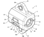
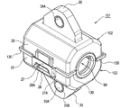
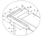
図1に示す雑音電流吸収具1は、電線L(図7参照)を流れる雑音電流を吸収するためにその電線Lの外周に装着されるものである。この雑音電流吸収具1は、同一形状(製造誤差はあってもよい。)の一対のユニット2,2を組み合わせて構成される。図2A〜図2Eに示すように、各ユニット2は、樹脂部品20(収容部の一例)と磁性体40とを備える。
[1. First Embodiment]
[1-1. overall structure]
The noise
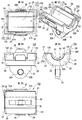
各磁性体40は、同一形状に形成されており、それぞれが半割筒状で、互いに当接させると全体として筒状になる形状とされている。各磁性体40の内側面41は円筒面状で、一対の磁性体40が突合せ面42同士を互いに突合せて筒状に組み合わせられた場合、円柱状の貫通穴99(図1参照)が形成される。その貫通穴99に電線Lが嵌合するように、一対のユニット2,2が組み合わせられる。一方のユニット2(すなわち一方の樹脂部品20及び磁性体40)は、前記貫通穴99の中心軸を中心に180度回転させると、ちょうど他方のユニット2と同一形状になる。なお、以下の説明において、各ユニット2に関して、突合せ面42側を上方、前記貫通穴99の中心軸方向を前後方向という場合がある。
Each
各樹脂部品20は、一方の磁性体40を底面(すなわち、内側面41及び突合せ面42とは反対側の面)の側から収容する凹部21を有している。凹部21における前後方向の一方の側に設けられた壁面23には、電線Lを貫通させる半円状の切欠23Aが形成され、他方の壁面24にも、同様に電線Lを貫通させる半円状の切欠24Aが形成されている。
Each
また、磁性体40の側面43,43を外側から支持する各樹脂部品20の側壁25,25の外側面には、一対の樹脂部品20,20が有する凹部21,21同士を互いに突合せた閉鎖時に、互いに係合する被係合部27及び係合部28が形成されている。被係合部27は、前後方向両端に形成された脚部27Aを介して側壁25から浮き上がった位置に架設され、全体として門型に形成されている。係合部28は、他の樹脂部品20における被係合部27と側壁25との間の空間に挿入可能なように上方に突出している。また、係合部28には、当該挿入後に被係合部27と係合する断面鉤状のフック28Aが形成されている。
Further, the outer surfaces of the
このため、前記閉鎖時には、一方の樹脂部品20に形成された係合部28のフック28Aが弾性変形しながら、他方の樹脂部品20に形成された被係合部27に係合する。また、他方の樹脂部品20に形成された係合部28のフック28Aが弾性変形しながら、一方の樹脂部品20に形成された被係合部27に係合する。これによって、一対の樹脂部品20,20は互いに固定され、各凹部21,21に収容された磁性体40,40は筒状となった閉鎖状態に維持されることになる。
For this reason, at the time of closing, the
また、このとき、各樹脂部品20における壁面23,24の外側に隣接して上方に突出するように各樹脂部品20と一体成形された壁30,30は、もう1つの樹脂部品20における壁面23,24の外側面に嵌合する。これによって、一対の樹脂部品20,20は一層良好に互いに固定される。なお、壁30,30の構成については、後に詳述する。
At this time, the
また、磁性体40の底面を外側(すなわち下側)から支持する各樹脂部品20の底29
には、ネジ穴35Aが穿設された固定部35が一体成形されている。この固定部35は、前後方向(互いに当接された磁性体40,40が構成する筒の中心軸方向)に沿って底29の表面に斜辺を有し、かつ、前記中心軸から離れる方向に延びる概略直角二等辺三角形板状に構成されている。そして、その斜辺と対向する頂点と前記斜辺の中点との中間位置に、固定部35を前記板の厚さ方向(すなわち左右方向)に貫通するネジ穴35Aが形成されている。また、ネジ穴35Aの開口部には、金属製のカラー35Bが設けられている。
Further, the bottom 29 of each
The fixing
[1−2.壁の詳細な構成]
ここで、ネジ穴35Aに図示省略したネジ(例えばボルト又はビス)を挿入してシャーシ等の装着対象に雑音電流吸収具1を装着する場合を想定する。その場合、ネジを締め付けて固定部35を装着対象に固定する際に、固定部35には、ネジの回転に応じて例えば図1に矢印F1で示すような力が加わる場合がある。すると、図1における下側の樹脂部品20の壁面24(図2参照)から突出した壁30に、前記力に応じて上側の樹脂部品20の壁面24が圧接される。同様に、図1における上側の樹脂部品20の壁面23から突出した壁30が、前記力に応じて下側の樹脂部品20の壁面23に圧接される。
[1-2. Detailed configuration of the wall]
Here, it is assumed that a screw (for example, a bolt or a screw) (not shown) is inserted into the
そこで、本実施形態では、壁30の大きさを次のように設計することによって、前記力によって樹脂部品20,20が互いにずれるのを抑制している。すなわち、図3に拡大して示すように、壁30は、前後左右上下方向にそれぞれ辺を有する直方体状(すなわち角柱状)に構成されている。また、壁30は、下端が樹脂部品20と一体に成形されているため、下端が樹脂部品20によって支持された片持ち梁と考えることができる。図3には、当該片持ち梁の断面とみなせる面に、ハッチングを施した。この面は、実際には断面ではなく壁30の上端面であるが、説明の便宜上、ハッチングを施した。
Therefore, in the present embodiment, the
もう一方の樹脂部品20が壁30に線接触し、その線接触する位置の樹脂部品20からの突出量(すなわち高さ)をhとし、壁30の前後方向の大きさ(すなわち厚さ)をT1とし、壁30の左右方向の大きさ(すなわち幅)をW1とする。すると、壁30にもう一方の樹脂部品20から加わる荷重Pと、壁30の変形量dとの間には、以下の関係がある。
The
W1=P・h3・12/(3・E・T13・d)
なお、Eはヤング率を表し、一般的に樹脂部品20に用いられる樹脂では1200となる。T1は、成形後に壁30として成立するために必要な最小寸法であり、0.6mmとして計算する。hは、この種の雑音電流吸収具1における樹脂部品20同士の隙間を考慮して、成形後に壁30として成立するために必要な最小寸法であり、0.5mmとして計算する。dは、変形の影響が無視できる値であり、仮に0.1であるとする。すなわち、本明細書においてずれるのを抑制するとは、ずれの影響が無視できることをいう。無視できる範囲は、用途等に応じて適宜設定することができる。
W1 = P · h 3 · 12 / (3 · E · T1 3 · d)
Note that E represents Young's modulus, which is generally 1200 for resins used for the
荷重Pは次のように推定する。自動車のエンジンルームに設置される雑音電流吸収具1の固定には、ネジ強度区分8.8以上を求められることが多い。ネジ穴35AがM6サイズのボルトに対応しているとすると、締め付けトルクは7.85N・mである。ネジ穴35Aの中心から壁30までの距離は、最短でも0.002mとなる。このため、全てのトルクが前記2つの壁30に加わるとすると、2つの壁30には最大393Nの力がかかり、2つの壁30に力が均等に分散されるとすると、1つの壁30はP=196.5Nの荷重に対して変形量dが0.1以下である必要がある。
The load P is estimated as follows. In order to fix the noise
従って、エンジンルームに設置されて前記のような荷重Pが加わっても雑音電流吸収具1に変形の影響が無視できるようするためには、W1≧3.8mmである必要がある。そ
こで、本実施形態では、壁30をT1≧0.6mm、W1≧3.8mmに設計した。なお、荷重Pを受ける壁30が1つだけであれば、W1≧7.6mmである必要がある。
Therefore, W1 ≧ 3.8 mm needs to be satisfied so that the influence of the deformation on the noise
[1−3.効果]
以上詳述した第1実施形態によれば、以下の効果が得られる。
(1A)このように構成された雑音電流吸収具1を電線Lに対して取り付けると、筒状になる一対の磁性体40が電線Lを外周側から取り囲み、これにより、一対の磁性体40が磁気的に閉磁路を形成して、所期の雑音電流吸収能が発揮されることになる。しかも、このような閉鎖状態は、被係合部27及び係合部28の係合によって良好に維持される。
[1-3. effect]
According to the first embodiment described in detail above, the following effects can be obtained.
(1A) When the noise /
(1B)雑音電流吸収具1が前述のようにネジを用いて装着対象に装着される際、図1における上側の樹脂部品20は、下側の樹脂部品20に対して相対的にずれようとする。このとき、各樹脂部品20は、他方の樹脂部品20の壁30に当接する。壁30の大きさは、前述のように、樹脂部品20同士が相対的にずれるのを抑制可能な大きさである。このため、係合部28及び被係合部27の係合によって閉鎖状態に維持された一対の樹脂部品20が、ネジを用いて装着対象に装着される際に、一対の樹脂部品20がずれるのを壁30によって良好に抑制することができる。
(1B) When the noise
(1C)各樹脂部品20には、ネジから加わる力が矢印F1の方向(第1の回転方向の一例)である場合に作用する壁30と、ネジから加わる力が矢印F1とは逆の方向(第2の回転方向の一例)である場合に作用する壁30とが備えられている。このため、ネジと装着対象との位置関係に応じて固定部35に加わる力の方向が逆転した場合にも、前述のように一対の樹脂部品20がずれるのを良好に抑制することができる。しかも、壁30は、各樹脂部品20にそれぞれ一体成形されている。このため、一方の樹脂部品20にのみ壁30を設けた場合に比べて、壁30の大きさは小さくすることができる。
(1C) Each
(1D)各壁30は、各樹脂部品20における、ネジ穴35Aから最も離れたところに形成されている。このため、樹脂部品20同士がずれるのを一層小さい力で抑制することができ、壁30の大きさは一層小さくすることができる。
(1D) Each
(1E)壁30は、各樹脂部品20における壁面23,24の外側に隣接して上方に突出するように各樹脂部品20と一体成形され、もう1つの樹脂部品20における壁面23,24の外側面に嵌合する。このため、壁30は、壁面23,24の内側に設けられた場合に比べて、樹脂部品20同士の突合せ面に埃やゴミが入り込むのも良好に抑制することができる。
(1E) The
[2.第2実施形態]
[2−1.第1実施形態との相違点]
第2実施形態は、基本的な構成は第1実施形態と同様であるため、共通する構成については説明を省略し、相違点を中心に説明する。なお、第1実施形態と同じ符号は、同一の構成を示すものであって、先行する説明を参照する。
[2. Second Embodiment]
[2-1. Difference from the first embodiment]
Since the basic configuration of the second embodiment is the same as that of the first embodiment, the description of the common configuration will be omitted, and the description will focus on the differences. Note that the same reference numerals as those in the first embodiment indicate the same configuration, and the preceding description is referred to.
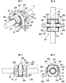
前述した第1実施形態の雑音電流吸収具1では、壁30を角柱状、すなわち片持ち梁として長方形状の断面を有する構成とした。これに対し、図4〜図6に示す第2実施形態の雑音電流吸収具101では、各ユニット102の樹脂部品20に一体成形された壁130が、L字状の断面を有する点で、第1実施形態と相違する。
In the noise
すなわち、図5A及び図6に示すように、壁130は、壁面23,24の外側面から突出した第1壁部131(壁の一例)と、側壁25の外側面から突出した第2壁部132(補助壁の一例)とが、互いに一体に、かつ、樹脂部品20とも一体に成形されている。
That is, as shown in FIGS. 5A and 6, the
また、一対の被係合部27,27と係合部28,28との係合によって一対の樹脂部品20,20が閉鎖状態に維持されたとき、壁130,130は、もう1つの樹脂部品20における壁面23,24及び側壁25の外側面に嵌合する。
In addition, when the pair of
[2−2.効果]
以上詳述した第2実施形態によれば、前述した第1実施形態の効果(1A)〜(1E)に加え、以下の効果が得られる。
[2-2. effect]
According to the second embodiment described in detail above, the following effects are obtained in addition to the effects (1A) to (1E) of the first embodiment described above.
(2A)壁130は、第2壁部132を有することにより、前記矢印F1で示した力に対する断面二次モーメントが大幅に向上する。例えば、第1壁部131の厚さT2が第1実施形態の壁30の厚さT1と同一で、第1壁部131の幅W2が1.9mmである場合、第2壁部132の前後方向の大きさ(すなわち厚さ)T3を0.9mmとし、第2壁部132の左右方向の大きさ(すなわち幅)を壁30の厚さT1と同じく0.6mmとすると、2つの壁130によって393N以上の力に耐えられる。なお、前記厚さT3とは、第1壁部131と第2壁部132との重複部分であるL字の角部を除いた大きさである。このため、壁130は、全体の長さ(すなわちW2+T3)が壁30の幅W1に比べて約26%短くなり、大幅な小型化が可能となる。
(2A) Since the
(2B)また、樹脂部品20,20が閉鎖状態に維持されたとき、壁130,130は、もう1つの樹脂部品20における壁面23,24及び側壁25の外側面に嵌合する。このため、一対の樹脂部品20,20は一層良好に固定され、樹脂部品20同士の突合せ面に埃やゴミが入り込むのも一層良好に抑制することができる。
(2B) When the
(2C)本実施形態では、樹脂部品20,20の突合せ面の四隅がL字状の壁130にそれぞれ嵌合している。このため、ネジの締め付け方向(すなわち矢印F1方向)のみならず、ネジの挿入方向における樹脂部品20のずれ又は撓みも抑制することができる。従って、一対の固定部35,35の平行度のずれに対する特性安定性も向上する。
(2C) In the present embodiment, the four corners of the butted surfaces of the
[3.第3実施形態]
[3−1.第2実施形態との相違点]
第3実施形態は、基本的な構成は第2実施形態と同様であるため、共通する構成については説明を省略し、相違点を中心に説明する。なお、第2実施形態と同じ符号は、同一の構成を示すものであって、先行する説明を参照する。
[3. Third Embodiment]
[3-1. Difference from Second Embodiment]
Since the basic configuration of the third embodiment is the same as that of the second embodiment, the description of the common configuration will be omitted, and the description will focus on the differences. In addition, the same code | symbol as 2nd Embodiment shows the same structure, Comprising: Prior description is referred.
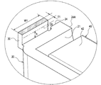
前述した第2実施形態の雑音電流吸収具101では、第1実施形態の雑音電流吸収具1と同様に、各樹脂部品20の底29に固定部35を設けた。これに対し、図7A〜図7Dに示す第3実施形態の雑音電流吸収具201では、各ユニット202の樹脂部品20が固定部35を有さず、代わりに、各樹脂部品20の外周面にリブ229が一体成形された点で、第2実施形態と相違する。
In the noise
リブ229は、一対の磁性体40,40が構成する筒の中心軸に直交し、かつ、所定間隔を空けた2つの平面に沿って設けられている。前記所定間隔とは、次のような帯状部材900の幅である。帯状部材900は、厚さ方向にU字状に湾曲した本体部901と、その本体部901の両端から外側に広がるように延びる一対の固定部902,902とを備えた金属性の部材である。各固定部902には、図示省略したネジ(例えばボルト又はビス)を挿入可能なネジ穴903が形成されている。
The
また、リブ229は、各樹脂部品20における各側壁25と底29との間に計4つずつ形成されており、底29とリブ229の端縁とは同一平面上に配設されるように構成され
ている。このため、底29及びリブ229の端縁をシャーシ等の平面(装着対象の一例)に当接させ、当該雑音電流吸収具201を挟んで帯状部材900を前記平面にネジを用いて固定することによって、雑音電流吸収具201は前記平面に固定される。このとき、帯状部材900の本体部901は、前記所定間隔を空けて配置されたリブ229の間に嵌り込んで、雑音電流吸収具201に対して位置決めする。このため、雑音電流吸収具201は、前記平面に固定される。
Further, a total of four
[3−2.効果]
このような第3実施形態でも、前述した(1A)〜(1E)及び(2A)〜(2C)と同様の効果が生じる。すなわち、この場合、図7Aに矢印F2で示すような力がネジの回転に応じて固定部902に加わると、図7Aにおける上側のユニット202には矢印F3で示すような力が加わるが、その力による樹脂部品20同士のずれも壁130によって抑制することができる。また、本実施形態では、雑音電流吸収具201に直接ネジを締め付けることなく、当該雑音電流吸収具201をシャーシ等の装着対象に装着することができる。
[3-2. effect]
Even in the third embodiment, the same effects as (1A) to (1E) and (2A) to (2C) described above are produced. That is, in this case, when a force as indicated by an arrow F2 in FIG. 7A is applied to the fixing
また、図7A〜図7Dに示すように、貫通穴99(図1参照)に電線Lが挿入され、かつ、その電線Lが前記平面に固定されていると、一層効果が顕著になる。その場合、図7Aにおける下側のユニット202には、リブ229の端縁及び底29と前記平面との間に作用する摩擦力に加えて、電線Lが磁性体40の内側面41に当接することによっても、そのユニット202の矢印F3方向への回転を抑制する力が作用する。従って、一対の樹脂部品20,20の間にずれが一層生じやすくなるが、本実施形態では、壁130によって当該ずれの発生を抑制することができる。なお、本実施形態において、壁130に代えて第1実施形態と同様の壁30を設けてもよい。
Further, as shown in FIGS. 7A to 7D, when the electric wire L is inserted into the through hole 99 (see FIG. 1) and the electric wire L is fixed to the plane, the effect becomes more remarkable. In this case, in the
[4.他の実施形態]
以上、本開示を実施するための形態について説明したが、本開示は上述の実施形態に限定されることなく、種々変形して実施することができる。
[4. Other Embodiments]
As mentioned above, although the form for implementing this indication was demonstrated, this indication is not limited to the above-mentioned embodiment, and can carry out various modifications.
(4A)前記第1及び第2実施形態では、各樹脂部品20の底29に固定部35を設けたが、これに限定されるものではない。例えば、固定部35は、左右いずれかの側壁25の外側面に、一対の磁性体40,40が構成する筒の中心軸から離れる方向に延びるように設けてもよい。
(4A) In the first and second embodiments, the fixing
(4B)前記各実施形態では、壁30又は壁130を樹脂部品20の外面に設けたが、これに限定されるものではない。壁は、樹脂部品20の内面(すなわち磁性体40との間の隙間)に設けられてもよい。
(4B) In each of the above embodiments, the
(4C)前記各実施形態では、一対の樹脂部品20,20のそれぞれに、一対の磁性体40,40の前記筒の中心を挟んで被係合部27及び係合部28を一対ずつ設けたが、これに限定されるものではない、被係合部27及び係合部28は、複数対ずつ設けられてもよい。また、左右の側壁25,25にそれぞれ1つ又は複数の被係合部27が設けられた樹脂部品20と、左右の側壁25,25にそれぞれ1つ又は複数の係合部28が設けられた樹脂部品20とが組み合わせられることによって、雑音電流吸収具が構成されてもよい。
(4C) In each of the embodiments, a pair of engaged
(4D)前記実施形態における1つの構成要素が有する複数の機能を、複数の構成要素によって実現したり、1つの構成要素が有する1つの機能を、複数の構成要素によって実現したりしてもよい。また、複数の構成要素が有する複数の機能を、1つの構成要素によって実現したり、複数の構成要素によって実現される1つの機能を、1つの構成要素によ
って実現したりしてもよい。また、前記実施形態の構成の一部を省略してもよい。また、前記実施形態の構成の少なくとも一部を、他の前記実施形態の構成に対して付加又は置換してもよい。なお、特許請求の範囲に記載した文言のみによって特定される技術思想に含まれるあらゆる態様が本開示の実施形態である。
(4D) A plurality of functions of one constituent element in the embodiment may be realized by a plurality of constituent elements, or a single function of one constituent element may be realized by a plurality of constituent elements. . Further, a plurality of functions possessed by a plurality of constituent elements may be realized by one constituent element, or one function realized by a plurality of constituent elements may be realized by one constituent element. Moreover, you may abbreviate | omit a part of structure of the said embodiment. In addition, at least a part of the configuration of the embodiment may be added to or replaced with the configuration of the other embodiment. In addition, all the aspects included in the technical idea specified only by the wording described in the claims are embodiments of the present disclosure.
[5.補足]
なお、以上説明した例示的な実施形態から明らかなように、本開示の雑音電流吸収具は、更に以下に挙げるような構成を備えていてもよい。
[5. Supplement]
As apparent from the exemplary embodiments described above, the noise current absorber of the present disclosure may further include the following configurations.
(5A)前記壁は、前記各収容部にそれぞれ一体成形されてもよい。その場合、壁が一方の収容部のみに設けられている場合に比べて、小さい壁であっても一層良好に一対の収容部がずれるのを抑制することができる。 (5A) The wall may be integrally formed in each housing part. In that case, compared with the case where a wall is provided only in one accommodating part, even if it is a small wall, it can suppress that a pair of accommodating part shift | deviates more favorably.
(5B)前記壁は、前記ネジが第1の回転方向に回転する場合に生じる前記ずれと、前記第1の回転方向とは異なる第2の回転方向に回転する場合に生じる前記ずれとを、それぞれ抑制するように複数設けられてもよい。その場合、ネジがいずれか一方に回転する場合に生じるずれに対してのみ壁が設けられた場合に比べ、ネジ穴と装着対象との配置が変わるなどして固定時におけるネジの回転方向が変わった場合にも、一対の収容部がずれるのを良好に抑制することができる。 (5B) The wall includes the deviation that occurs when the screw rotates in the first rotation direction and the deviation that occurs when the wall rotates in a second rotation direction different from the first rotation direction. A plurality may be provided so as to suppress each. In that case, the rotation direction of the screw at the time of fixing is changed compared to the case where a wall is provided only for the displacement that occurs when the screw rotates in either direction, such as the arrangement of the screw hole and the mounting target. Also in this case, it is possible to satisfactorily prevent the pair of accommodating portions from shifting.
(5C)前記壁が、前記閉鎖時に前記他方の収容部の外側面に嵌合してもよい。その場合、一対の収容部が一層良好に互いに固定され、かつ、収容部同士の突合せ面に埃やゴミが入り込むのも良好に抑制することができる。 (5C) The wall may be fitted to an outer surface of the other housing portion when the wall is closed. In that case, it is possible to satisfactorily prevent the pair of storage portions from being fixed to each other more satisfactorily and dust and dirt to enter the abutting surfaces of the storage portions.
(5D)前記各収容部の外側にそれぞれ一体成形され、前記筒又は環の中心軸に直交する方向に前記ネジを挿入可能なネジ穴を有して前記装着対象に固定される一対の固定部を、更に備え、前記壁は、前記各収容部における前記中心軸に沿った方向における端面にそれぞれ一体成形されてもよい。前記一対の固定部を備えた場合、各固定部のネジ穴にネジを挿入して締め付けることによって、各固定部は装着対象に固定され、雑音電流吸収具が装着対象に装着される。その固定時には、前記中心軸に沿った方向の力が一方の収容部に加わるが、壁が収容部における前記中心軸に沿った方向における端面にそれぞれ一体成形されていれば、前記力によって一対の収容部がずれるのを良好に抑制することができる。 (5D) A pair of fixing portions that are integrally formed on the outside of each housing portion and have screw holes into which the screws can be inserted in a direction perpendicular to the center axis of the cylinder or ring, and are fixed to the mounting target Further, the wall may be integrally formed on an end surface in a direction along the central axis in each housing portion. When the pair of fixing portions are provided, each fixing portion is fixed to the mounting target by inserting and tightening a screw into the screw hole of each fixing portion, and the noise current absorber is mounted on the mounting target. At the time of fixing, a force in the direction along the central axis is applied to one accommodating portion. However, if the wall is integrally formed on the end surface of the accommodating portion in the direction along the central axis, It is possible to satisfactorily prevent the housing portion from shifting.
(5E)そして、その場合、前記壁は、前記各収容部にそれぞれ一体成形され、かつ、前記一対の収容部の突合せ方向に一辺を有する角柱状に構成され、前記角柱は、前記突合せ方向に直交する断面が前記中心軸に沿って短辺を有する長方形に構成され、前記短辺が0.6mm以上で、前記断面における長辺が3.8mm以上であってもよい。その場合、前述のように、当該雑音電流吸収具を自動車のエンジンルーム等において良好に使用することができる。 (5E) In this case, the wall is integrally formed in each of the housing portions, and is configured in a prismatic shape having one side in the butting direction of the pair of housing portions, and the prism is in the butting direction. The orthogonal cross section may be configured as a rectangle having a short side along the central axis, the short side may be 0.6 mm or more, and the long side in the cross section may be 3.8 mm or more. In that case, as described above, the noise current absorber can be used favorably in an automobile engine room or the like.
(5F)また、前記(5D)の場合において、前記壁には、前記中心軸に沿って伸び、前記一方の収容部とも一体成形された補助壁が一体成形され、前記壁は、前記補助壁と協働することによって、前記他方の収容部が前記ネジの回転に応じて前記一方の収容部に対して相対的にずれるのを抑制可能な大きさを有してもよい。その場合、壁及び補助壁に対して必要とされる両者を合わせた大きさは、補助壁を設けない場合に前記壁に対して必要とされる大きさに比べて良好に小さくすることができる。 (5F) In the case of (5D), an auxiliary wall that extends along the central axis and is integrally formed with the one housing portion is integrally formed on the wall, and the wall is the auxiliary wall. By cooperating with, the other accommodating portion may have a size capable of suppressing the relative displacement with respect to the one accommodating portion according to the rotation of the screw. In that case, the size required for both the wall and the auxiliary wall can be made smaller than the size required for the wall when the auxiliary wall is not provided. .
(5G)そして、その場合、前記壁は、前記各収容部にそれぞれ一体成形され、かつ、前記一対の収容部の突合せ方向に一辺を有する角柱状に構成され、前記角柱は、前記突合せ方向に直交する断面が前記中心軸に沿って短辺を有する長方形に構成され、前記短辺が
0.6mm以上で、前記断面における長辺が1.9mm以上であり、前記補助壁の前記中心軸に沿った大きさは0.9mm以上であり、前記補助壁の前記中心軸及び前記突合せ方向に直交する大きさは0.6mm以上であってもよい。その場合、前述のように、当該雑音電流吸収具を自動車のエンジンルーム等において良好に使用することができる。
(5G) In this case, the wall is formed integrally with each of the housing portions, and is configured in a prismatic shape having one side in the butting direction of the pair of housing portions, and the prism is in the butting direction. An orthogonal cross section is configured as a rectangle having a short side along the central axis, the short side is 0.6 mm or more, a long side in the cross section is 1.9 mm or more, and the central axis of the auxiliary wall is The size of the auxiliary wall may be 0.9 mm or more, and the size of the auxiliary wall perpendicular to the central axis and the butting direction may be 0.6 mm or more. In that case, as described above, the noise current absorber can be used favorably in an automobile engine room or the like.
なお、この(5G)及び前述の(5E)では、大きさを下限値だけしか示していないが、それらの大きさはなるべく小さい値とされることが好ましい場合が多く、大きさの上限値は用途等に応じて自ずと決まる値である。 In (5G) and (5E) described above, only the lower limit value is shown, but in many cases, it is preferable that these sizes be as small as possible, and the upper limit value of the size is It is a value that is naturally determined according to the application.
(5H)また、前記(5F)又は(5G)の場合において、前記壁及び前記補助壁が、前記閉鎖時に前記他方の収容部の外周面に嵌合してもよい。その場合、一対の収容部が一層良好に互いに固定され、かつ、収容部同士の突合せ面に埃やゴミが入り込むのも良好に抑制することができる。 (5H) Further, in the case of (5F) or (5G), the wall and the auxiliary wall may be fitted to the outer peripheral surface of the other housing portion at the time of closing. In that case, it is possible to satisfactorily prevent the pair of storage portions from being fixed to each other more satisfactorily and dust and dirt to enter the abutting surfaces of the storage portions.
(5I)また、ネジを挿入可能なネジ穴を両端に有する帯状部材が、前記雑音電流吸収具を挟んで装着対象にネジを用いて固定される際に、前記帯状部材を前記収容部の外周面において挟むように、少なくともいずれか一方の前記収容部に突出成形されたガイド辺を、更に備えてもよい。その場合、当該雑音電流吸収具に直接ネジを締め付けることなく、ガイド辺の間に嵌まり込んだ帯状部材を介して当該雑音電流吸収具を装着対象に装着することができる。また、このような雑音電流吸収具の装着時には、帯状部材に対するネジの締め付けによって収容部同士が相対的にずれようとするが、そのように収容部同士が相対的にずれるのも前述のように抑制することができる。 (5I) When a band-shaped member having screw holes into which screws can be inserted at both ends is fixed to a mounting object with the noise current absorber sandwiched between the band-shaped member and the outer periphery of the housing portion You may further provide the guide edge protrudingly shape | molded by the at least any one said accommodating part so that it may pinch | interpose in a surface. In this case, the noise current absorber can be mounted on the mounting target via a belt-like member fitted between the guide sides without directly tightening a screw on the noise current absorber. In addition, when such a noise current absorber is mounted, the accommodating portions tend to be relatively displaced by tightening the screws with respect to the belt-like member, but the accommodating portions are relatively displaced as described above. Can be suppressed.
1,101,201…雑音電流吸収具 2,102,202…ユニット
20…樹脂部品 21…凹部
23,24…壁面 25…側壁
27…被係合部 28…係合部
30,130…壁 35,902…固定部
35A…ネジ穴 40…磁性体
131…第1壁部 132…第2壁部
229…リブ 900…帯状部材
901…本体部 903…ネジ穴
DESCRIPTION OF SYMBOLS 1,101,201 ... Noise current absorber 2,102,202 ...
Claims (6)
それぞれが凹部を有し、当該各凹部には、前記一対の磁性体のそれぞれを収容可能で、前記各凹部に前記各磁性体が収容された状態で前記凹部同士を互いに突合せた閉鎖時には、前記一対の磁性体が筒状又は環状になる一対の収容部と、
前記一対の収容部のそれぞれに、前記一対の磁性体の前記筒又は環の中心を挟んでそれぞれ設けられ、前記閉鎖時に互いに係合することで、前記一対の磁性体が筒状又は環状になった閉鎖状態を維持可能な係合部及び被係合部と、
少なくとも一方の前記収容部における他方の前記収容部との突合せ面に隣接して、前記少なくとも一方の収容部に一体成形され、前記他方の収容部が突き合わせられる側に突出した壁と、
を備え、
前記壁が前記突合せ面に隣接する側は、前記閉鎖状態が維持されている前記一対の収容部が当該一対の収容部の装着対象にネジを用いて装着される際に前記ネジの回転に応じて前記他方の収容部が前記一方の収容部に対して相対的にずれようとする側であり、
前記壁の大きさは、前記他方の収容部と当接することによって当該収容部が前記ネジの回転に応じて前記一方の収容部に対して相対的にずれるのを抑制可能な大きさである、雑音電流吸収具。 A pair of magnetic bodies that are generally cylindrical or annular when brought into contact with each other;
Each has a recess, and in each recess, each of the pair of magnetic bodies can be accommodated, and when the recesses abut each other in a state where the respective magnetic bodies are accommodated in the respective recesses, A pair of accommodating portions in which the pair of magnetic bodies are cylindrical or annular; and
Each of the pair of accommodating portions is provided with the center of the cylinder or ring of the pair of magnetic bodies interposed therebetween, and is engaged with each other at the time of closing, so that the pair of magnetic bodies becomes cylindrical or annular. An engaging part and an engaged part capable of maintaining a closed state;
A wall that is integrally formed with the at least one housing portion adjacent to the butting surface of the at least one housing portion with the other housing portion, and protrudes to the side with which the other housing portion is butted.
With
The side where the wall is adjacent to the abutting surface responds to the rotation of the pair of screws when the pair of accommodating parts maintained in the closed state are attached to the object to be attached to the pair of accommodating parts. The other accommodating portion is a side that is about to be displaced relative to the one accommodating portion,
The size of the wall is a size capable of suppressing the relative displacement of the housing portion with respect to the one housing portion according to the rotation of the screw by contacting the other housing portion. Noise current absorber.
更に備え、
前記壁は、前記各収容部における前記中心軸に沿った方向における端面にそれぞれ一体成形された請求項1又は2に記載の雑音電流吸収具。 A pair of fixing portions that are integrally formed on the outside of each housing portion and have screw holes into which the screws can be inserted in a direction perpendicular to the central axis of the cylinder or ring, and are fixed to the mounting target.
In addition,
3. The noise current absorber according to claim 1, wherein the wall is integrally formed on an end surface in a direction along the central axis in each housing portion.
前記壁は、前記補助壁と協働することによって、前記他方の収容部が前記ネジの回転に応じて前記一方の収容部に対して相対的にずれるのを抑制可能な大きさを有する、請求項3に記載の雑音電流吸収具。 The wall is integrally formed with an auxiliary wall that extends along the central axis and is integrally formed with the one housing portion.
The said wall has a magnitude | size which can suppress that the said other accommodating part shifts relatively with respect to said one accommodating part according to rotation of the said screw by cooperating with the said auxiliary wall. Item 4. The noise current absorber according to Item 3.
Priority Applications (2)
| Application Number | Priority Date | Filing Date | Title |
|---|---|---|---|
| JP2016093474A JP6735971B2 (en) | 2016-05-06 | 2016-05-06 | Noise current absorber |
| US15/585,244 US10165714B2 (en) | 2016-05-06 | 2017-05-03 | Noise current absorber |
Applications Claiming Priority (1)
| Application Number | Priority Date | Filing Date | Title |
|---|---|---|---|
| JP2016093474A JP6735971B2 (en) | 2016-05-06 | 2016-05-06 | Noise current absorber |
Publications (2)
| Publication Number | Publication Date |
|---|---|
| JP2017201670A true JP2017201670A (en) | 2017-11-09 |
| JP6735971B2 JP6735971B2 (en) | 2020-08-05 |
Family
ID=60244202
Family Applications (1)
| Application Number | Title | Priority Date | Filing Date |
|---|---|---|---|
| JP2016093474A Active JP6735971B2 (en) | 2016-05-06 | 2016-05-06 | Noise current absorber |
Country Status (2)
| Country | Link |
|---|---|
| US (1) | US10165714B2 (en) |
| JP (1) | JP6735971B2 (en) |
Cited By (1)
| Publication number | Priority date | Publication date | Assignee | Title |
|---|---|---|---|---|
| JP2021086967A (en) * | 2019-11-29 | 2021-06-03 | 北川工業株式会社 | Noise filter |
Families Citing this family (2)
| Publication number | Priority date | Publication date | Assignee | Title |
|---|---|---|---|---|
| TWM557968U (en) * | 2017-11-02 | 2018-04-01 | 和碩聯合科技股份有限公司 | Shielding case |
| DE102019114522A1 (en) * | 2019-05-29 | 2020-12-03 | Valeo Siemens Eautomotive Germany Gmbh | Device with a busbar arrangement, a filter device and a cover, associated manufacturing process, as well as power converter and drive device |
Citations (8)
| Publication number | Priority date | Publication date | Assignee | Title |
|---|---|---|---|---|
| DE8902517U1 (en) * | 1989-03-02 | 1989-05-11 | Siemens Ag, 1000 Berlin Und 8000 Muenchen, De | |
| JPH0582015U (en) * | 1992-02-03 | 1993-11-05 | 北川工業株式会社 | Noise absorber |
| US6633000B2 (en) * | 2001-02-23 | 2003-10-14 | Hon Hai Precision Ind. Co., Ltd. | Noise filter with an improved insulating case |
| JP2009129780A (en) * | 2007-11-26 | 2009-06-11 | Autonetworks Technologies Ltd | Shielded conductive body |
| DE102014001558A1 (en) * | 2012-11-29 | 2014-06-05 | Intel Mobile Communications GmbH | CAPACITIVE HIGH FREQUENCY DIGITAL ANALOG TRANSDUCER WITH A SWITCHABLE LOAD |
| JP2014110343A (en) * | 2012-12-03 | 2014-06-12 | Kitagawa Ind Co Ltd | Ferrite clamp |
| JP2015035476A (en) * | 2013-08-08 | 2015-02-19 | 北川工業株式会社 | Holder and noise current absorber |
| JP2015198189A (en) * | 2014-04-02 | 2015-11-09 | 北川工業株式会社 | Noise countermeasure component |
Family Cites Families (3)
| Publication number | Priority date | Publication date | Assignee | Title |
|---|---|---|---|---|
| JPH0291903A (en) | 1988-09-29 | 1990-03-30 | Murata Mfg Co Ltd | Ferrite core with seat |
| JP5633008B2 (en) * | 2009-10-22 | 2014-12-03 | 北川工業株式会社 | Holder and noise current absorber |
| US20150208519A1 (en) * | 2012-09-19 | 2015-07-23 | Kitagawa Industries Co., Ltd. | Ferrite clamp |
-
2016
- 2016-05-06 JP JP2016093474A patent/JP6735971B2/en active Active
-
2017
- 2017-05-03 US US15/585,244 patent/US10165714B2/en active Active
Patent Citations (8)
| Publication number | Priority date | Publication date | Assignee | Title |
|---|---|---|---|---|
| DE8902517U1 (en) * | 1989-03-02 | 1989-05-11 | Siemens Ag, 1000 Berlin Und 8000 Muenchen, De | |
| JPH0582015U (en) * | 1992-02-03 | 1993-11-05 | 北川工業株式会社 | Noise absorber |
| US6633000B2 (en) * | 2001-02-23 | 2003-10-14 | Hon Hai Precision Ind. Co., Ltd. | Noise filter with an improved insulating case |
| JP2009129780A (en) * | 2007-11-26 | 2009-06-11 | Autonetworks Technologies Ltd | Shielded conductive body |
| DE102014001558A1 (en) * | 2012-11-29 | 2014-06-05 | Intel Mobile Communications GmbH | CAPACITIVE HIGH FREQUENCY DIGITAL ANALOG TRANSDUCER WITH A SWITCHABLE LOAD |
| JP2014110343A (en) * | 2012-12-03 | 2014-06-12 | Kitagawa Ind Co Ltd | Ferrite clamp |
| JP2015035476A (en) * | 2013-08-08 | 2015-02-19 | 北川工業株式会社 | Holder and noise current absorber |
| JP2015198189A (en) * | 2014-04-02 | 2015-11-09 | 北川工業株式会社 | Noise countermeasure component |
Cited By (1)
| Publication number | Priority date | Publication date | Assignee | Title |
|---|---|---|---|---|
| JP2021086967A (en) * | 2019-11-29 | 2021-06-03 | 北川工業株式会社 | Noise filter |
Also Published As
| Publication number | Publication date |
|---|---|
| US10165714B2 (en) | 2018-12-25 |
| JP6735971B2 (en) | 2020-08-05 |
| US20170325367A1 (en) | 2017-11-09 |
Similar Documents
| Publication | Publication Date | Title |
|---|---|---|
| JP5484182B2 (en) | clip | |
| JP5065647B2 (en) | Storage structure of electrical junction box in storage box | |
| JP2017201670A (en) | Noise current absorber | |
| US10205255B2 (en) | Battery terminal stopper and battery terminal unit | |
| US10849247B2 (en) | Vehicle-mounted electronic device including a substrate inside a housing | |
| WO2013146855A1 (en) | Electric component connection unit and junction box | |
| US9774155B2 (en) | Assembling structure of bus bar | |
| JP2013110170A (en) | Ferrite clamp | |
| JP5785727B2 (en) | Article mounting structure | |
| JP5807661B2 (en) | Fuel tank | |
| US20160135310A1 (en) | Holder and noise current absorber | |
| JP2015063231A (en) | Fuel tank and fuel tank attachment structure | |
| WO2016080047A1 (en) | Bracket for vibration-damping device and vibration-damping device | |
| JP2019009047A (en) | Connector and connector attachment structure | |
| JP2018204674A (en) | Vibration proofing device | |
| JP2017089671A (en) | Pipe clamp | |
| JP6801208B2 (en) | Battery module | |
| JP2020032972A (en) | Vehicle door structure | |
| JP7256076B2 (en) | electric junction box | |
| JP7428615B2 (en) | resin structure | |
| JP6164551B2 (en) | Holder and noise current absorber | |
| JP2018078238A (en) | Noise current absorption tool | |
| JP2017004650A (en) | Fuse unit | |
| JP5448633B2 (en) | connector | |
| JP2017011810A (en) | Protector and wire harness fixing structure |
Legal Events
| Date | Code | Title | Description |
|---|---|---|---|
| A621 | Written request for application examination |
Free format text: JAPANESE INTERMEDIATE CODE: A621 Effective date: 20190328 |
|
| A977 | Report on retrieval |
Free format text: JAPANESE INTERMEDIATE CODE: A971007 Effective date: 20191031 |
|
| A131 | Notification of reasons for refusal |
Free format text: JAPANESE INTERMEDIATE CODE: A131 Effective date: 20191112 |
|
| A521 | Request for written amendment filed |
Free format text: JAPANESE INTERMEDIATE CODE: A523 Effective date: 20200109 |
|
| TRDD | Decision of grant or rejection written | ||
| A01 | Written decision to grant a patent or to grant a registration (utility model) |
Free format text: JAPANESE INTERMEDIATE CODE: A01 Effective date: 20200512 |
|
| A61 | First payment of annual fees (during grant procedure) |
Free format text: JAPANESE INTERMEDIATE CODE: A61 Effective date: 20200527 |
|
| R150 | Certificate of patent or registration of utility model |
Ref document number: 6735971 Country of ref document: JP Free format text: JAPANESE INTERMEDIATE CODE: R150 |
|
| R250 | Receipt of annual fees |
Free format text: JAPANESE INTERMEDIATE CODE: R250 |