JP2017201521A - Output control unit, output control system, and method for controlling output control unit - Google Patents
Output control unit, output control system, and method for controlling output control unit Download PDFInfo
- Publication number
- JP2017201521A JP2017201521A JP2017088769A JP2017088769A JP2017201521A JP 2017201521 A JP2017201521 A JP 2017201521A JP 2017088769 A JP2017088769 A JP 2017088769A JP 2017088769 A JP2017088769 A JP 2017088769A JP 2017201521 A JP2017201521 A JP 2017201521A
- Authority
- JP
- Japan
- Prior art keywords
- output
- unit
- control unit
- warning
- instruction
- Prior art date
- Legal status (The legal status is an assumption and is not a legal conclusion. Google has not performed a legal analysis and makes no representation as to the accuracy of the status listed.)
- Pending
Links
Images


Classifications
-
- G—PHYSICS
- G05—CONTROLLING; REGULATING
- G05B—CONTROL OR REGULATING SYSTEMS IN GENERAL; FUNCTIONAL ELEMENTS OF SUCH SYSTEMS; MONITORING OR TESTING ARRANGEMENTS FOR SUCH SYSTEMS OR ELEMENTS
- G05B11/00—Automatic controllers
- G05B11/01—Automatic controllers electric
- G05B11/36—Automatic controllers electric with provision for obtaining particular characteristics, e.g. proportional, integral, differential
- G05B11/42—Automatic controllers electric with provision for obtaining particular characteristics, e.g. proportional, integral, differential for obtaining a characteristic which is both proportional and time-dependent, e.g. P.I., P.I.D.
-
- G—PHYSICS
- G05—CONTROLLING; REGULATING
- G05B—CONTROL OR REGULATING SYSTEMS IN GENERAL; FUNCTIONAL ELEMENTS OF SUCH SYSTEMS; MONITORING OR TESTING ARRANGEMENTS FOR SUCH SYSTEMS OR ELEMENTS
- G05B19/00—Programme-control systems
- G05B19/02—Programme-control systems electric
- G05B19/04—Programme control other than numerical control, i.e. in sequence controllers or logic controllers
- G05B19/05—Programmable logic controllers, e.g. simulating logic interconnections of signals according to ladder diagrams or function charts
- G05B19/054—Input/output
-
- G—PHYSICS
- G05—CONTROLLING; REGULATING
- G05B—CONTROL OR REGULATING SYSTEMS IN GENERAL; FUNCTIONAL ELEMENTS OF SUCH SYSTEMS; MONITORING OR TESTING ARRANGEMENTS FOR SUCH SYSTEMS OR ELEMENTS
- G05B13/00—Adaptive control systems, i.e. systems automatically adjusting themselves to have a performance which is optimum according to some preassigned criterion
- G05B13/02—Adaptive control systems, i.e. systems automatically adjusting themselves to have a performance which is optimum according to some preassigned criterion electric
- G05B13/0205—Adaptive control systems, i.e. systems automatically adjusting themselves to have a performance which is optimum according to some preassigned criterion electric not using a model or a simulator of the controlled system
- G05B13/024—Adaptive control systems, i.e. systems automatically adjusting themselves to have a performance which is optimum according to some preassigned criterion electric not using a model or a simulator of the controlled system in which a parameter or coefficient is automatically adjusted to optimise the performance
-
- G—PHYSICS
- G05—CONTROLLING; REGULATING
- G05B—CONTROL OR REGULATING SYSTEMS IN GENERAL; FUNCTIONAL ELEMENTS OF SUCH SYSTEMS; MONITORING OR TESTING ARRANGEMENTS FOR SUCH SYSTEMS OR ELEMENTS
- G05B19/00—Programme-control systems
- G05B19/02—Programme-control systems electric
- G05B19/04—Programme control other than numerical control, i.e. in sequence controllers or logic controllers
- G05B19/05—Programmable logic controllers, e.g. simulating logic interconnections of signals according to ladder diagrams or function charts
-
- G—PHYSICS
- G05—CONTROLLING; REGULATING
- G05D—SYSTEMS FOR CONTROLLING OR REGULATING NON-ELECTRIC VARIABLES
- G05D23/00—Control of temperature
- G05D23/19—Control of temperature characterised by the use of electric means
- G05D23/1919—Control of temperature characterised by the use of electric means characterised by the type of controller
-
- G—PHYSICS
- G05—CONTROLLING; REGULATING
- G05D—SYSTEMS FOR CONTROLLING OR REGULATING NON-ELECTRIC VARIABLES
- G05D23/00—Control of temperature
- G05D23/19—Control of temperature characterised by the use of electric means
- G05D23/30—Automatic controllers with an auxiliary heating device affecting the sensing element, e.g. for anticipating change of temperature
-
- G—PHYSICS
- G08—SIGNALLING
- G08B—SIGNALLING OR CALLING SYSTEMS; ORDER TELEGRAPHS; ALARM SYSTEMS
- G08B21/00—Alarms responsive to a single specified undesired or abnormal condition and not otherwise provided for
- G08B21/18—Status alarms
-
- G—PHYSICS
- G05—CONTROLLING; REGULATING
- G05B—CONTROL OR REGULATING SYSTEMS IN GENERAL; FUNCTIONAL ELEMENTS OF SUCH SYSTEMS; MONITORING OR TESTING ARRANGEMENTS FOR SUCH SYSTEMS OR ELEMENTS
- G05B2219/00—Program-control systems
- G05B2219/20—Pc systems
- G05B2219/26—Pc applications
- G05B2219/2614—HVAC, heating, ventillation, climate control
Abstract
Description
本発明は、制御装置からの情報に応じて、出力装置の出力制御を行う出力制御ユニットに関する。 The present invention relates to an output control unit that performs output control of an output device in accordance with information from a control device.
従来、ファクトリーオートメーション(FA)の分野では、PLC(プログラマブルロジックコントローラ)等のコントローラが、各種入出力ユニットを制御し、当該入出力ユニットが入出力装置とデータを送受信するシステム構成がとられている。図7は、従来の出力制御システムの概要を示す図である。同図では一例として、ヒータを用いて対象物の温度制御を行うシステムを示している。図示の通り、コントローラは各種ユニットに対し種々の指示または情報を送信し、各種ユニットが入出力装置(例えば温度センサ)からデータを収集する。 Conventionally, in the field of factory automation (FA), a system configuration has been adopted in which a controller such as a PLC (programmable logic controller) controls various input / output units, and the input / output units transmit / receive data to / from an input / output device. . FIG. 7 is a diagram showing an outline of a conventional output control system. In the figure, as an example, a system for controlling the temperature of an object using a heater is shown. As illustrated, the controller transmits various instructions or information to various units, and the various units collect data from the input / output device (for example, a temperature sensor).
図7に示すような出力制御システムでは、ヒータの駆動および停止の切り替えを行う回路であるSSR(Solid State Relay)が、CT(Current Transformer)から電流値を読み取る。そして、SSRは電流値からヒータが正常に駆動または停止しているかを判定し、断線などの異常が起きたと判定した場合は、該判定結果を、デジタル入力ユニットを介してコントローラに送信していた。 In the output control system as shown in FIG. 7, an SSR (Solid State Relay) that is a circuit for switching between driving and stopping of the heater reads a current value from a CT (Current Transformer). Then, the SSR determines whether the heater is normally driven or stopped from the current value, and when it is determined that an abnormality such as disconnection has occurred, the determination result is transmitted to the controller via the digital input unit. .
しかしながら、ヒータ等の出力装置の挙動を監視する機能を持つSSRは高価であり、導入には高いコストがかかる。また、SSRはデジタル出力ユニット、デジタル入力ユニット、およびCTと配線されるため、配線が複雑になりがちである。また、SSRが複数存在する場合、挙動監視のための各種設定を各SSRに対し行わねばならないので、設定に手間がかかる。例えば、複数の出力装置に1つずつSSRが接続されている場合、各出力装置がどのような挙動を示した時に異常と検知するかを、各SSRに設定する必要がある。 However, an SSR having a function of monitoring the behavior of an output device such as a heater is expensive and expensive to introduce. Further, since the SSR is wired with the digital output unit, the digital input unit, and the CT, the wiring tends to be complicated. In addition, when there are a plurality of SSRs, various settings for behavior monitoring must be performed on each SSR, which takes time and effort. For example, when one SSR is connected to each of a plurality of output devices, it is necessary to set in each SSR what kind of behavior each output device will detect as abnormal.
本発明は、上記の問題点に鑑みてなされたものであり、その目的は、より簡易な構成で出力装置の異常を制御装置に通知することにある。 The present invention has been made in view of the above-described problems, and an object of the present invention is to notify an abnormality of an output device to a control device with a simpler configuration.
前記の課題を解決するために、本発明に係る出力制御ユニットは、制御装置から出力装置の出力に係る情報を取得する取得部と、前記情報に従って、前記出力装置の駆動と停止とを切り替える切替装置に対し、前記出力装置の駆動または停止を指示する指示出力部と、前記出力装置の実動作を直接または間接的に測定する測定装置から、前記出力装置の実動作を示す情報を取得する測定値取得部と、前記切替装置に対する指示と、前記実動作を示す情報とから、前記指示出力部が前記切替装置に出力した指示通りに前記出力装置が駆動または停止しているか否かを判定する判定部と、前記判定部が、前記指示通りに前記出力装置が駆動または停止していないと判定した場合、警告を出力する警告出力部と、を備えることを特徴とする。 In order to solve the above-described problem, an output control unit according to the present invention includes an acquisition unit that acquires information relating to an output of an output device from a control device, and switching that switches between driving and stopping of the output device according to the information. Measurement that acquires information indicating the actual operation of the output device from an instruction output unit that instructs the device to drive or stop the output device and a measurement device that directly or indirectly measures the actual operation of the output device From the value acquisition unit, the instruction to the switching device, and the information indicating the actual operation, it is determined whether or not the output device is driven or stopped according to the instruction output by the instruction output unit to the switching device. And a warning output unit that outputs a warning when the determination unit determines that the output device has not been driven or stopped as instructed.
前記の課題を解決するために、本発明に係る出力制御ユニットの制御方法は、制御装置から出力装置の出力に係る情報を取得する取得ステップと、前記情報に従って、前記出力装置の駆動と停止とを切り替える切替装置に対し、前記出力装置の駆動または停止を指示する指示出力ステップと、前記出力装置の実動作を直接または間接的に測定する測定装置から、前記出力装置の実動作を示す情報を取得する電流値取得ステップと、前記切替装置に対する指示と、前記実動作を示す情報とから、前記指示出力ステップにて前記切替装置に出力した指示通りに前記出力装置が駆動または停止しているか否かを判定する判定ステップと、前記判定ステップにて、前記指示通りに前記出力装置が駆動または停止していないと判定した場合、警告を出力する警告出力ステップと、を含むことを特徴とする。 In order to solve the above-described problem, a control method of an output control unit according to the present invention includes an acquisition step of acquiring information relating to an output of an output device from a control device, and driving and stopping of the output device according to the information. Information indicating the actual operation of the output device from the instruction output step for instructing the driving or stopping of the output device to the switching device for switching between and the measuring device for directly or indirectly measuring the actual operation of the output device. Whether or not the output device is driven or stopped according to the instruction output to the switching device in the instruction output step from the current value acquisition step to be acquired, the instruction to the switching device, and the information indicating the actual operation When the determination step determines that the output device is not driven or stopped as instructed in the determination step, a warning is output. Characterized in that it comprises a warning output step that, a.
前記の構成および処理によれば、出力制御ユニットは、切替装置に対する指示内容、すなわち、出力装置を駆動させる旨の指示、または停止させる旨の指示と、出力装置の実動作を示す情報とから、指示通りに出力装置の駆動および停止が行われているか否か判定することができる。そして、出力装置の駆動および停止が正常に行われていない場合に警告を出力することができる。 According to the above-described configuration and processing, the output control unit, from the instruction content to the switching device, that is, the instruction to drive or stop the output device, and the information indicating the actual operation of the output device, It can be determined whether or not the output device is driven and stopped as instructed. A warning can be output when the output device is not normally driven and stopped.
また、前記の構成および処理によれば、出力装置が指示通り駆動または停止しているかを切替装置に監視させる場合に比べ、切替装置の導入コストを低減することができるとともに、配線工数を少なくすることができる。さらには、切替装置に対し、上述の出力装置の監視に係る各種設定を行う手間を省くことができる。したがって、出力制御ユニットは、より簡易な構成で出力装置の異常を通知することができる。 In addition, according to the configuration and processing described above, the introduction cost of the switching device can be reduced and the wiring man-hours can be reduced as compared with the case where the switching device monitors whether the output device is driven or stopped as instructed. be able to. Furthermore, it is possible to save the trouble of performing various settings related to the monitoring of the output device described above for the switching device. Therefore, the output control unit can notify the abnormality of the output device with a simpler configuration.
また、前記出力制御ユニットにおいて、前記警告出力部が出力した前記警告は、前記制御装置によって取得されてもよい。これにより、出力制御ユニットは、自ユニットの上流で出力制御を行っている制御装置に、警告を出力することができる。 In the output control unit, the warning output by the warning output unit may be acquired by the control device. As a result, the output control unit can output a warning to the control device that performs output control upstream of the unit itself.
また、前記出力制御ユニットにおいて、前記警告出力部は、前記取得部が前記制御装置から前記警告の解除命令を取得するまで、前記警告を出力し続けてもよい。 In the output control unit, the warning output unit may continue to output the warning until the acquisition unit acquires the warning cancellation command from the control device.
前記の構成によれば、出力制御ユニットは、出力した警告を制御装置が認識し、解除命令という反応を返すまで警告を出力し続ける。これにより、出力制御ユニットは、制御装置に警告を確実に認識させることができる。 According to the above configuration, the output control unit continues to output the warning until the control device recognizes the output warning and returns a response of a release command. Thereby, the output control unit can make a control apparatus recognize a warning reliably.
また、前記出力制御ユニットにおいて、前記警告出力部は、前記警告をユーザに通知する出力装置と接続されており、前記出力装置を介して前記警告を出力してもよい。前記の構成によれば、出力制御ユニットは、制御装置等の指示を介さずとも、自己が発する警告を出力装置に出力させることができる。これにより、例えば制御装置等の上位の機器が故障している場合でも、ユーザに警告を通知することができる。 In the output control unit, the warning output unit may be connected to an output device that notifies the user of the warning, and the warning may be output via the output device. According to the above configuration, the output control unit can cause the output device to output a warning issued by itself without using an instruction from the control device or the like. Thus, for example, even when a higher-level device such as a control device is out of order, a warning can be notified to the user.
また、前記出力制御ユニットにおいて、前記測定値取得部は、前記測定装置から前記出力装置を流れる電流の値を取得し、前記判定部は、前記切替装置に対する指示と、前記電流の値とから、前記指示出力部が前記切替装置に出力した指示通りに前記出力装置が駆動または停止しているか否かを判定してもよい。 Further, in the output control unit, the measurement value acquisition unit acquires a value of a current flowing through the output device from the measurement device, and the determination unit is based on an instruction to the switching device and the value of the current. It may be determined whether or not the output device is driven or stopped according to the instruction output by the instruction output unit to the switching device.
前記の構成によれば、出力制御ユニットは例えば断線や切替装置の故障などにより、出力装置の駆動が正常に行われていない場合を検出し、警告を出力することができる。 According to the above configuration, the output control unit can detect a case where the output device is not normally driven due to disconnection or a failure of the switching device, and can output a warning.
また、前記出力制御ユニットにおいて、前記取得部は、前記制御装置から前記情報を周期的に取得してもよい。これにより、出力制御ユニットは、前記情報の取得周期の影響を受けずに、出力装置の出力制御指示、および指示内容に基づき出力装置が指示通り駆動または停止しているかの判定を行うことができる。 In the output control unit, the acquisition unit may periodically acquire the information from the control device. Accordingly, the output control unit can determine whether the output device is driven or stopped as instructed based on the output control instruction of the output device and the content of the instruction without being affected by the information acquisition cycle. .
また、前記出力制御ユニットにおいて、前記取得部は、フィールドネットワークを介して前記制御装置と接続してもよい。フィールドネットワークによって通信を行う場合、サイクリックに通信が行われることがある。これに対して前記の構成によれば、出力制御ユニットは、通信のサイクルの影響を受けずに、出力装置の出力制御指示、および指示内容に基づき出力装置が指示通り駆動または停止しているかの判定を行うことができる。 In the output control unit, the acquisition unit may be connected to the control device via a field network. When communication is performed via a field network, communication may be performed cyclically. On the other hand, according to the above configuration, the output control unit determines whether the output device is driven or stopped as instructed based on the output control instruction of the output device and the content of the instruction without being affected by the communication cycle. Judgment can be made.
また、前記出力制御ユニットにおいて、前記判定部は、前記指示出力部が前記切替装置に対して前記出力装置を駆動させるよう指示しており、前記測定値取得部が取得した電流の値が、前記出力装置の駆動中の電流値の下限値よりも低い第1閾値以下である場合に、前記指示出力部が前記切替装置に出力した指示通りに前記出力装置が駆動または停止されていないと判定してもよい。 In the output control unit, the determination unit instructs the instruction output unit to drive the output device to the switching device, and the value of the current acquired by the measurement value acquisition unit is When the output device is equal to or lower than a first threshold value lower than the lower limit value of the current value during driving, it is determined that the output device is not driven or stopped as instructed by the instruction output unit to the switching device. May be.
前記の構成によれば、出力制御ユニットは、例えば断線などにより、出力装置を駆動させる旨の指示を出力したが、出力装置が実際は駆動していない場合を検知し、警告を出力することができる。 According to the above configuration, the output control unit outputs an instruction to drive the output device due to, for example, disconnection, but can detect a case where the output device is not actually driven and output a warning. .
また、前記出力制御ユニットにおいて、前記判定部は、前記指示出力部が前記切替装置に対して前記出力装置を停止させるよう指示しており、前記測定値取得部が取得した電流の値が、前記出力装置の停止中の電流値の上限値よりも高い第2閾値以上である場合に、前記指示出力部が前記切替装置に出力した指示通りに前記出力装置が駆動または停止されていないと判定してもよい。 Further, in the output control unit, the determination unit instructs the instruction output unit to stop the output device to the switching device, and the value of the current acquired by the measurement value acquisition unit is When the output device is greater than or equal to a second threshold value that is higher than the upper limit value of the current value when the output device is stopped, it is determined that the output device is not driven or stopped as instructed by the instruction output unit to the switching device. May be.
前記の構成によれば、出力制御ユニットは、例えば切替装置の故障などにより、出力装置を停止させる旨の指示を出力したが、出力装置が実際は停止していない場合を検知し、警告を出力することができる。 According to the above configuration, the output control unit outputs an instruction to stop the output device due to, for example, a failure of the switching device, but outputs a warning when the output device is not actually stopped. be able to.
また、前記出力制御ユニットにおいて、前記指示出力部は、複数の切替装置に対して個別に駆動または停止を指示し、前記測定値取得部は、各切替装置の駆動および停止の切り替え対象である各出力装置に接続された測定装置から、各出力装置の実動作を示す情報を個別に取得し、前記判定部は前記判定を出力装置毎に行い、前記警告出力部は、出力装置毎に異なった前記警告を出力してもよい。 Further, in the output control unit, the instruction output unit individually instructs a plurality of switching devices to drive or stop, and the measurement value acquisition unit is a switching target of driving and stopping of each switching device. Information indicating the actual operation of each output device is individually acquired from a measurement device connected to the output device, the determination unit performs the determination for each output device, and the warning output unit is different for each output device. The warning may be output.
前記の構成によれば、出力制御ユニットは、複数の出力装置の駆動および停止が正常に行われているかを個々の出力装置について判定し、警告を出力することができる。したがって、出力制御ユニットは、いずれの出力装置に異常が生じているのかが分かるように警告を出力することができる。 According to the above configuration, the output control unit can determine whether each of the output devices is normally driven and stopped, and output a warning. Therefore, the output control unit can output a warning so that it can be understood which output device has an abnormality.
前記の課題を解決するために、本発明に係る出力制御システムは、前記出力制御ユニットと、前記制御装置とを含むことを特徴とする。これにより、より簡易な構成で出力装置の異常を制御装置に通知することが可能な出力制御システムを実現することができる。 In order to solve the above problems, an output control system according to the present invention includes the output control unit and the control device. Thereby, it is possible to realize an output control system capable of notifying the control device of an abnormality in the output device with a simpler configuration.
本発明は、より簡易な構成で出力装置の異常を制御装置に通知することができるという効果を奏する。 The present invention has an effect that an abnormality of an output device can be notified to a control device with a simpler configuration.
〔実施形態1〕
以下、本発明の第1の実施形態について、図1〜4を参照して説明する。まず始めに、本実施形態に係る出力制御システム100について、図1および図2を用いて説明する。
Embodiment 1
Hereinafter, a first embodiment of the present invention will be described with reference to FIGS. First, the
≪システムに含まれる装置と接続関係≫
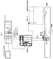
出力制御システム100は、ある対象物(例えば樹脂、水など)の温度を調節するためのシステムであって、温度調節に使われるヒータや冷却装置などの駆動および停止が正常に行われているか否かを検知するためのシステムである。まず始めに、図2を用いて、出力制御システム100に含まれる各装置(ユニット)と、その接続関係について説明する。図2は、出力制御システム100の概要を示す図である。出力制御システム100は少なくとも、コントローラ(制御装置)2と、温度制御ユニット(出力制御ユニット)3と、ヒータ(出力装置)7と、SSR(Solid State Relay、切替装置)8と、CT(Current Transformer、測定装置)9とを含んでいる。また、出力制御システム100は、必須構成ではないが、プログラマブル表示器1と、温度入力ユニット4と、温度センサ5とを含んでいてもよい。
≪Devices and connections in the system≫
The
図示の通り、コントローラ2はプログラマブル表示器1、温度制御ユニット3、および温度入力ユニット4と通信カプラを介しフィールドネットワークで接続している。また、温度制御ユニット3はコントローラ2、SSR8、およびCT9と接続している。また、温度入力ユニット4は、コントローラ2および温度センサ5と接続している。さらに、SSR8、CT9、およびヒータ7は、ヒータ電源とともに電線で接続されている。
As shown in the figure, the controller 2 is connected to the programmable display 1, the temperature control unit 3, and the temperature input unit 4 through a communication coupler via a field network. The temperature control unit 3 is connected to the controller 2, SSR8, and CT9. The temperature input unit 4 is connected to the controller 2 and the
≪各装置の要部構成≫
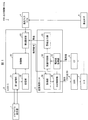
次に、図1を用いて、各装置(ユニット)の働きについて説明する。図1は、出力制御システム100に含まれる装置およびユニットの要部構成を示すブロック図である。
≪Essential configuration of each device≫
Next, the function of each device (unit) will be described with reference to FIG. FIG. 1 is a block diagram showing a main configuration of devices and units included in the
(プログラマブル表示器1)
プログラマブル表示器1は、コントローラ2から受信したデータや通知を、自端末から出力する(表示部に表示させる、またはアラームなどの音声出力を行う)ことで上記データや通知をユーザに提示するHMI(Human Machine Interface)である。なお、プログラマブル表示器1は入力部を備え、当該入力部から受け付けたユーザの指示をコントローラ2に送信してもよい。
(Programmable display 1)
The programmable display device 1 outputs the data and notification received from the controller 2 from its own terminal (displays on the display unit or performs voice output such as an alarm), and presents the data and notification to the user. Human Machine Interface). The programmable display device 1 may include an input unit, and may transmit a user instruction received from the input unit to the controller 2.
(コントローラ2)
コントローラ2は、フィールドネットワークの通信網(以降、単に通信網と称する)を周回するデータブロックを受け取り、該データブロックに各種データを含めて上記通信網に返すPLC(プログラマブルロジックコントローラ)である。ここで、データブロックとは、通信網に接続された各種機器の間で周回する(周期的にやりとりされる)データの集合体を示す。データブロックの周回の周期は、コントローラ2のサイクルタイムに応じて決定される。
(Controller 2)
The controller 2 is a PLC (programmable logic controller) that receives a data block that circulates in a field network communication network (hereinafter simply referred to as a communication network) and returns various data in the data block to the communication network. Here, the data block refers to an aggregate of data that circulates (periodically exchanges) between various devices connected to the communication network. The cycle of the data block is determined according to the cycle time of the controller 2.
詳しくは後述するが、通信網に接続された温度制御ユニット3が該データブロックを受け取り、各種データを読み取る。また、コントローラ2は、温度制御ユニット3および温度入力ユニット4がデータブロックに含めた各種データを読み取る。コントローラ2はより詳しくは、第1通信部21、記憶部22、第2通信部23、および制御部20を含む。
As will be described in detail later, the temperature control unit 3 connected to the communication network receives the data block and reads various data. The controller 2 reads various data included in the data block by the temperature control unit 3 and the temperature input unit 4. More specifically, the controller 2 includes a
第1通信部21は、コントローラ2とプログラマブル表示器1との間の通信を行うものである。第1通信部21は制御部20から各種データおよび警告を受信すると、これをプログラマブル表示器1に送信する。また、第1通信部21はプログラマブル表示器1からユーザの指示を受信すると、これを制御部20に送信する。
The
記憶部22は、ユーザプログラムを格納する。ここで、ユーザプログラムとは、コントローラ2の各種動作および設定を規定したプログラムである。ユーザプログラムは、汎用コンピュータ等にインストールされた設定ツール(アプリケーション)等を用いて作成され、上記汎用コンピュータと接続されたコントローラ2にダウンロードされ、記憶部22に格納される。ユーザプログラムは例えば、ヒータ7の駆動および停止を経時的に規定するプログラムを含む。ユーザプログラムは、制御部20により読み出され、実行される。
The
第2通信部23は、コントローラ2と温度制御ユニット3および温度入力ユニット4との間の通信を行うものである。第2通信部23はデータブロックに制御部20が作成した制御命令を示す、または制御に係る各種パラメータの値等を示す情報を含めて、通信網に返す。同通信網に接続している温度制御ユニット3は、該データブロックを受け取ることで、該情報を取得する。
The
また第2通信部23は、データブロックに、温度制御ユニット3からの、ヒータ7が断線している旨の警告(以下、単に警告と称する)が含まれていた場合、該警告を制御部20に送る。また、第2通信部23は、データブロックに温度入力ユニット4からの温度データ(温度調節の対象物の温度を示す情報)が含まれていた場合、該温度データを制御部20に送る。
If the data block includes a warning from the temperature control unit 3 that the heater 7 is disconnected (hereinafter simply referred to as a warning), the
制御部20はコントローラ2を統括的に制御するものである。制御部20は、記憶部22から読み出したユーザプログラムを実行することによって、もしくは、自装置にて予め定められた方法で、温度調節に係る情報(制御命令または各種パラメータ等)を作成する。ここで、「温度調節に係る情報」とは、コントローラ2が出力する情報であって、ヒータ7の駆動および停止を規定する情報である。制御部20は作成した情報を、第2通信部23を介し出力する。なお、制御部20はデータブロックに含まれるデータを読み取ることで取得した温度データに基づいて、上記情報の内容、例えばヒータ7の駆動および停止の度合いを調節してもよい。
The
(温度制御ユニット3)
温度制御ユニット3は、コントローラ2からの情報に応じてSSR8に時分割比例出力(TPO)で指示を出すユニットである。また、温度制御ユニット3はSSR8に送信した指示内容と、CT9から取得した電流値から、ヒータ7が断線しているか否かを判定し、断線していると判定した場合はコントローラ2に警告を送るユニットである。温度制御ユニット3は、より詳しくは、取得部30、SSR制御部(指示出力部)32、電流値取得部(測定値取得部)33、判定部34、および警告出力部35を含む。
(Temperature control unit 3)
The temperature control unit 3 is a unit that gives an instruction to the
取得部30は、コントローラ2から情報を取得し、SSR制御部32に当該情報を送る。また、取得部30はコントローラ2から警告イベントの解除指示(警告の解除命令、後述)を取得してもよい。警告イベントの解除指示を取得した場合、取得部30は当該解除指示を警告出力部35に送信する。
The
SSR制御部32は、取得部30から取得した情報に従って、SSR8にヒータ7の駆動指示または停止指示を送信する。ここで、駆動指示および停止指示は、TPOの方式で出力される。電流値取得部33は、SSR制御部32がSSR8に対し指示を送信したタイミングで、CT9から、ヒータ7を流れる電流の値(電流値)を取得し、電流値を判定部34に送る。
The
判定部34は、SSR8に送信した指示内容(駆動指示または停止指示)と電流値とから、ヒータ7が指示通り駆動または停止しているか、もしくは断線しているかを判定する。より具体的には、判定部34は、SSR8に送信した指示が、ヒータ7の駆動指示であり、かつ、電流値取得部33から取得した電流値が所定の断線判定閾値(第1閾値)以下である場合に、ヒータ7が断線していると判定する。なお、断線判定閾値はヒータ7の駆動中の電流値の下限値よりも低い値で、適宜定めればよい。判定部34は、ヒータ7が断線していると判定した場合、当該判定結果を警告出力部35に送る。
The
警告出力部35は、判定部34からヒータ7が断線している旨の判定結果を受信すると、警告を作成しコントローラ2に出力する。警告出力部35が出力する警告は、コントローラ2が監視情報の1つとして扱うための情報(監視情報としての警告)であってもよい。また、警告出力部35が出力する警告は、コントローラ2から何らかの警告解除の指示を受けるまで警告を発し続ける警告(軽度フォールト)であってもよい。
When the
(SSR8、CT9、およびヒータ7)
SSR8は、ヒータ7の起動および停止(ONおよびOFF)を制御する回路である。SSR8は、温度制御ユニット3のSSR制御部32から受信した駆動指示または停止指示に応じて、ヒータ7を駆動または停止させる。CT9は、ヒータ7に流れる電流値を測定する。すなわち、CT9は、ヒータ7の実動作を測定しているといえる。CT9はヒータ7に流れる電流を直接的に測定してもよいし、間接的に測定してもよい。CT9は測定結果を温度制御ユニット3の電流値取得部33に送信する。ヒータ7は樹脂や水などの温度制御の対象物を温める。ヒータ7は、電気駆動し対象物に熱を伝えることができるものであればその構成は問わない。
(SSR8, CT9, and heater 7)
The
(温度センサ5および温度入力ユニット4)
温度センサ5は、温度制御の対象物の温度を計り、温度入力ユニット4に送信する。温度入力ユニット4は当該温度を示す温度データをコントローラ2に出力する。
(
The
図1および図2の例では、判定部34は、ヒータ7という1装置について断線しているか否かの判定を行う構成とした。しかしながら、本発明に係る出力制御システム100において、判定部34は複数装置の断線の有無をそれぞれ装置別に判定し、警告出力部35はいずれの装置が断線しているかが区別可能な警告をコントローラ2に出力してもよい。
In the example of FIGS. 1 and 2, the
より具体的に言えば、例えば出力制御システム100はSSR8、CT9、およびヒータ7、(およびヒータ電源)から成る図2に示した電気回路を複数備えるとすると、SSR制御部32は、複数のSSRに対して個別に駆動または停止を指示する。そして電流値取得部33は、各SSRの駆動および停止の切り替え対象である各ヒータにそれぞれ接続されたCTから、各ヒータに流れる電流の値を個別に取得し、判定部34は断線判定をヒータ毎に行う。そして警告出力部35は、ヒータ毎に異なった警告を出力する。これにより、複数のヒータの断線をそれぞれ個別に検出し、警告を発することができる。
More specifically, for example, if the
≪ヒータ断線の判定方法≫
次に、判定部34が行う判定について、図3を用いてより詳しく説明する。図3の(a)は、温度制御ユニット3における入出力パラメータの経時的変化を示すタイミングチャートである。
≪Method for judging heater breakage≫
Next, the determination performed by the
「指示出力」行は、SSR制御部32からSSR8に対する指示出力のタイミングおよび指示の変化を示す行であり、「ON」はヒータ7を駆動させる指示を示し、「OFF」はヒータ7を停止させる指示を示す。「CT電流値」行は、電流値取得部33がCT9から取得する電流値の変化を示す。ここで、遮断時電流値とはヒータ7が停止中の電流値を示す。一方、導通時電流値とは、ヒータ7が駆動中の電流値を示す。また、断線判定閾値は上述の通り、ヒータ7の駆動中の電流値の下限値よりも低い値で任意に定められた閾値である。
The “instruction output” line is a line indicating timing of instruction output from the
「警告(監視情報時)」行および「警告(軽度フォールト時)」行はそれぞれ、警告出力部35が警告を出力しているタイミングを示している。「警告(監視情報時)」行は、監視情報としての警告を出力する場合を、「警告(軽度フォールト時)」は軽度フォールトとしての警告を出力する場合を示している。
The “Warning (at the time of monitoring information)” line and the “Warning (at the time of minor fault)” line indicate the timing at which the
「イベント解除」列は、警告出力部35が軽度フォールトとしての警告を出力する場合に、取得部30がコントローラ2から警告イベントの解除指示を取得するタイミングを示している。なお、監視情報としての警告を出力する場合、当行に示すような解除指示の取得は起こらない。
The “event release” column indicates the timing at which the
上述したように、SSR制御部32はTPOでSSR8に対し駆動指示および停止指示を送る。換言すると、駆動指示を出し続ける期間と、停止指示を出し続ける期間とを1組としたものが、1制御周期となる。ここで、図3の(a)の初めの制御周期に示すように、SSR制御部32が駆動指示を出力しているときに電流値取得部33が取得した電流値(すなわち、CT9が測定した電流値)が断線判定閾値を下回った場合、判定部34はヒータ7が断線していると判定し、当該判定を受けて警告出力部35は監視情報としての警告、または軽度フォールトとしての警告をコントローラ2に出力する。そして、軽度フォールトとしての警告をコントローラ2に出力した場合、コントローラ2の制御部20は、上記警告を取得すると所定の条件(例えば当該警告に対し、何らかの処置済であるなど)を満たした場合に、警告イベントの解除指示を温度制御ユニット3の取得部30に対し出力する。取得部30は当該解除指示を受けると、これを警告出力部35に送信する。警告出力部35はイベントの解除指示を受けると、軽度フォールトとしての警告の出力を停止する。
As described above, the
なお、判定部34は、電流値取得部33から受信する電流値が所定の回数連続して断線判定閾値を下回った場合に、ヒータ7が断線していると判定してもよい。図3の(b)は、「CT電流値」行と「警告」行(監視情報時および軽度フォールト時の両行)とをさらに詳しく示したものである。「CT電流値」行の1プロットは、CT9が電流値をサンプリングするタイミングを示している。また、「警告」行の実線は監視情報としての警告の出力タイミングを、破線は軽度フォールトとしての警告の出力タイミングを示している。
The
図3の(b)に示す通り、判定部34は、一度ヒータ7が断線していると判定してから、電流値取得部33から受信する電流値が所定回数、断線判定閾値+所定のバッファ値(図中の断線判定ヒステリシス)以上の値になった場合に、ヒータ7が断線していないと判定してもよい。このように、ヒータ7の断線有無を、所定の回数分の電流値のプロットから判定することで、判定部34は誤判定を少なくすることができる。
As shown in FIG. 3B, the
≪警告出力処理の流れ≫
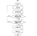
最後に、本実施形態において、温度制御ユニット3が警告を出力する処理(警告出力処理)の流れについて、図4を用いて説明する。図4は、警告出力処理の流れを示すフローチャートである。
≪Warning output process flow≫
Finally, in the present embodiment, the flow of processing (warning output processing) in which the temperature control unit 3 outputs a warning will be described with reference to FIG. FIG. 4 is a flowchart showing the flow of the warning output process.
コントローラ2から温度調節に係る情報を取得すると、温度制御ユニット3の取得部30は、当該情報をSSR制御部32に送る。SSR制御部32は、情報に応じて、ヒータ7を駆動または停止させる旨の指示を作成し、SSR8に送信する(S10)とともに判定部34に送る。一方、電流値取得部33は、SSR制御部32がSSR8に指示を送信したタイミングで、CT9から電流値を取得する(S11)。電流値取得部33は取得した電流値を判定部34に送る。
When acquiring information related to temperature adjustment from the controller 2, the
判定部34は、SSR制御部32がヒータ7を駆動させる旨の指示を送信していた場合(S12でYES)、かつ、電流値取得部33から受信した電流値が断線判定閾値以下である場合(S13でYES)、ヒータ7が断線していると判定する(S14)。判定部34は判定結果を警告出力部35に送信する。警告出力部35は、判定部34から受信した判定結果に基づき、警告を作成して出力する(S15)。
When the
一方、SSR制御部32がヒータ7を停止させる旨の指示を送信していた場合(S12でNO)、または、電流値取得部33から受信した電流値が断線判定閾値より大きい場合(S13でNO)、判定部34はヒータ7は正常に制御されていると判定し、次にSSR制御部32および電流値取得部33から指示内容および電流値を受信するまで待機する。
On the other hand, when the
上記処理によれば、温度制御ユニット3は、SSR8に対する指示内容、すなわち、ヒータ7を駆動させる旨の指示、または停止させる旨の指示と、ヒータ7を流れる電流値とから、SSR8に指示した通りにヒータ7が駆動または停止しているか否か判定することができる。そして、ヒータ7の駆動および停止が正常に行われていない場合、自ユニットの上流で出力制御を行っているコントローラ2に、警告を出力することができる。
According to the above processing, the temperature control unit 3 performs the instruction from the contents of the instruction to the
また、上記処理によれば、ヒータ7の駆動および停止が正常に行われているか否かをSSR8に監視および判断させる場合に比べ、SSR8の導入コストを低減することができる。また、SSR8とCT9を配線する必要がないため、配線工数を少なくすることができる。さらには、SSR8に対し、ヒータ7の監視に係る各種設定を行う手間を省くことができる。したがって、温度制御ユニット3は、より簡易な構成でヒータ7の異常を発見し、コントローラ2に警告することができる。
Further, according to the above processing, the introduction cost of the
なお、本実施形態において、判定部34は、SSR制御部32がSSR8に対しヒータ7の停止指示を出力しているタイミングで電流値取得部33が取得した電流の値が、所定の閾値(第2閾値)以上である場合、SSR8の故障などの問題によりヒータ7が正常に制御されていないと判定してもよい。そして、判定部34は警告出力部35に当該判定結果を伝え、警告出力部35は警告をコントローラ2に出力してもよい。
In the present embodiment, the
さらに言えば、警告出力部35は、判定部34が「ヒータ7が断線した」と判定した場合と、「SSR8が故障した」と判定した場合とで、異なる警告(コントローラ2が区別可能な警告)を出力してもよい。
Furthermore, the
また、本実施形態において、温度制御ユニット3は、警告をユーザに通知するための出力装置と接続されていてもよい。出力装置とは、例えばスピーカおよびマイクロフォン等である。そして、温度制御ユニット3の警告出力部35は、コントローラ2に警告を出力するのではなく、もしくは、コントローラ2に警告を出力するとともに、上記接続された出力装置を介して、警告を出力してもよい。
In the present embodiment, the temperature control unit 3 may be connected to an output device for notifying the user of a warning. Examples of the output device include a speaker and a microphone. The
これにより、温度制御ユニット3は、コントローラ2の指示を介さずとも、自己が発する警告を出力装置に出力させることができる。例えば、コントローラ2またはプログラマブル表示器1等、温度制御ユニット3の上位の機器のいずれかが故障しており、警告が上位の機器に上手く伝わらない場合でも、ユーザに警告を通知することができる。 Thereby, the temperature control unit 3 can cause the output device to output a warning issued by itself without going through the instruction of the controller 2. For example, even when any one of the upper devices of the temperature control unit 3 such as the controller 2 or the programmable display 1 is out of order and the warning is not transmitted well to the upper device, the user can be notified of the warning.
〔実施形態2〕
本発明に係る温度制御ユニット3は、単位時間当たりの、出力装置を駆動させる時間の割合を示す操作量をコントローラ2から取得し、SSR8に対し、一定周期かつ操作量が示す時間割合が実現できるように、ヒータ7を駆動または停止させるための指示を時分割比例出力(TPO)してもよい。以下、本発明の第2の実施形態について、図5を用いて説明する。なお、本実施形態および以降の実施形態では、説明の便宜上、実施形態1にて説明した部材と同じ機能を有する部材については、同じ符号を付記し、その説明を省略する。
[Embodiment 2]
The temperature control unit 3 according to the present invention acquires an operation amount indicating a ratio of time for driving the output device per unit time from the controller 2, and can realize a time ratio indicated by the operation amount with a constant period for the SSR8. As described above, an instruction for driving or stopping the heater 7 may be time-division proportional output (TPO). Hereinafter, a second embodiment of the present invention will be described with reference to FIG. In the present embodiment and the following embodiments, for convenience of explanation, members having the same functions as those described in the first embodiment are denoted by the same reference numerals and description thereof is omitted.
本実施形態において、コントローラ2の制御部20は第2通信部23を介し、操作量を温度制御ユニット3に出力する。すなわち、第2通信部23は、データブロックに操作量の値を含めて、通信網に返す。ここで、「操作量」とは、SSR8がヒータ7を駆動させるときの、該ヒータ7を駆動させる時間割合を指定する値である。以降の説明では一例として、制御部20は操作量としてヒータ7を駆動させる時間の割合を百分率(%)で示した値を決定し、出力することとする。
In the present embodiment, the
温度制御ユニット3の取得部30は上記操作量を取得し、SSR制御部32に送信する。SSR制御部32は上記操作量が示す時間割合が実現できるように、SSR8に対し駆動指示および停止指示を組み合わせた時分割比例出力(TPO)を行う。
The
図5は、取得部30が取得する(コントローラ2の制御部20が指示した)操作量の変化と、SSR制御部32の指示出力の変化とを示したタイミングチャートである。図示の通り、「操作量」行は取得部30が取得した操作量の値(%)を示す。また、「TPO出力」列は、SSR制御部32がSSR8に送信(出力)するTPOにおける指示の内容(ヒータ7のONまたはOFF)と、その期間とを示している。また、点a〜cは操作量が変わるタイミングを、矢印A〜Cおよびは対応する点a〜cにおける操作量の変化が反映されるタイミングを示している。
FIG. 5 is a timing chart showing the change in the operation amount acquired by the acquisition unit 30 (instructed by the
図示の通り、取得部30が取得する操作量が変化した場合、SSR制御部32は、変化後の操作量を、現在のTPOの制御周期中、またはその次の制御周期において反映させる。
As shown in the figure, when the operation amount acquired by the
より具体的には、SSR制御部32が停止指示を出力しているタイミングで操作量が変化した場合(図中の点a)、SSR制御部32は次の制御周期から、変化後の操作量に応じた駆動時間でTPOを行えばよい(図中の矢印A)。また、SSR制御部32が駆動指示を出力しているタイミングで操作量が変化した場合(図中の点b)、SSR制御部32は現在の制御周期におけるヒータ7の駆動時間の割合が、変化後の操作量が示す時間割合となるように、駆動指示を出力する期間を調整してTPOを行えばよい(図中の矢印B)。
More specifically, when the operation amount changes at the timing when the
また、SSR制御部32が駆動指示を出力しているタイミングで操作量が変化し、かつ、その時点の制御周期において、変更後の操作量が示す駆動時間以上の駆動時間がすでに経過していた場合(図中の点c)、SSR制御部32は、即時停止指示を出力し、当該制御周期の残りの時間は停止指示を出力し続ければよい(図中の矢印C)。この場合、次の制御周期から、変更後の操作量が正確に反映されることとなる(図中の矢印C´)。
Further, the operation amount has changed at the timing when the
このように温度制御ユニット3がコントローラ2から操作量の値を取得し、SSR制御部32においてTPOを行うことにより、制御部20のサイクルタイムやTPOの制御周期を意識せずに操作量が定められた場合でも、当該操作量をTPOに適切に反映させることができるという効果を奏する。
In this way, the temperature control unit 3 acquires the value of the operation amount from the controller 2 and performs TPO in the
〔実施形態3〕
また、本発明に係る温度制御ユニット3は、ヒータ7の駆動および停止に係る第1情報と、SSR8へのTPOを自律制御するか否かを示す第2情報とをコントローラ2から取得してもよい。また、温度制御ユニット3は、該第1情報および第2情報に従って、ヒータ7の駆動または停止の指示をTPOで、SSR8に出力してもよい。
[Embodiment 3]
Further, the temperature control unit 3 according to the present invention may obtain from the controller 2 the first information related to the driving and stopping of the heater 7 and the second information indicating whether or not to autonomously control the TPO to the
ここで、第1情報とは、例えば上記実施形態で説明した操作量であってもよいし、ヒータ7をON(駆動)させる旨、またはヒータ7をOFF(停止)させる旨の制御命令であってもよい。なお、第2情報については、本実施形態にて説明する。 Here, the first information may be, for example, the operation amount described in the above embodiment, or a control command for turning on (driving) the heater 7 or turning off (stopping) the heater 7. May be. The second information will be described in this embodiment.
以下、本発明の第3の実施形態について、図6を用いて説明する。本実施形態に係るコントローラ2は、操作量(第1情報)と、即出力指令のONまたはOFFを示す情報(第2情報)とを温度制御ユニット3に送信する点で、実施形態1および2に係るコントローラ2と異なる。また、温度制御ユニット3は、上記操作量と、上記即出力指令がONであるかOFFであるかに従って、SSR8に対するTPOの制御方法を変える点で、実施形態1および2に係る温度制御ユニット3と異なる。
Hereinafter, a third embodiment of the present invention will be described with reference to FIG. The controller 2 according to the present embodiment transmits the operation amount (first information) and information (second information) indicating ON or OFF of the immediate output command to the temperature control unit 3 in the first and second embodiments. It differs from the controller 2 which concerns on. Further, the temperature control unit 3 is different from the temperature control unit 3 according to the first and second embodiments in that the TPO control method for the
ここで、「即出力指令」とは、ONおよびOFFの2値をとる情報であって、温度制御ユニット3にSSR8へのTPOを自律制御させるか否かを示す情報である。以降の説明では、即出力指令がONの場合、温度制御ユニット3はTPOを自律制御しないこととし、即出力指令がOFFの場合、温度制御ユニット3はTPOを自律制御することとする。
Here, the “immediate output command” is information that takes binary values of ON and OFF, and is information that indicates whether or not the temperature control unit 3 autonomously controls the TPO to the
ここで、「TPOを自律制御する」とは、温度制御ユニット3が、自装置の内部情報に基づいて、例えばSSR8へのTPOの開始および終了タイミング、ならびにTPOの制御周期を定めることを示す。即出力指令がONの場合、温度制御ユニット3は、コントローラ2から出力されたTPOの開始および終了の指示、または該開始および終了タイミングを示す情報を、データブロックを介してサイクリックに取得する。そして、温度制御ユニット3は、該指示または該情報に従ってTPOの開始および終了、ならびにTPOの制御周期の変更を行う。
Here, “autonomous control of TPO” indicates that the temperature control unit 3 determines, for example, the start and end timing of the TPO to the
逆に言えば、「TPOを自律制御しない」とは、温度制御ユニット3が、コントローラ2から取得する情報(例えば、制御命令または各種パラメータ等)に基づいて、例えばSSR8へのTPOの開始および終了タイミング、ならびにTPOの制御周期の少なくとも1つを定めることを示す。
Conversely, “Do not autonomously control TPO” means that the temperature control unit 3 starts and ends the TPO to the
また、制御部20はヒータ7のオートチューニング機能を備えていてもよい。本実施形態で言う「オートチューニング機能」とは、コントローラ2で実行されるPID制御などの出力制御に係る各種パラメータを算出する機能を示す。
Further, the
さらに言えば、コントローラ2はオートチューニングを実行する場合に、即出力指令の値としてONを示す値をデータブロックに格納し、該ブロックを出力してもよい。また、コントローラ2はオートチューニングを実行しない場合は、即出力指令の値としてOFFを示す値をデータブロックに格納し、該ブロックを出力してもよい。以下、コントローラ2はオートチューニングを実行する場合に、即出力指令の値としてONを示す値をデータブロックに格納し、オートチューニングを実行しない場合、即出力指令の値としてONを示す値をデータブロックに格納することとして、説明を行う。 Furthermore, when executing auto-tuning, the controller 2 may store a value indicating ON as a value of the immediate output command in a data block and output the block. If the controller 2 does not execute auto-tuning, the controller 2 may store a value indicating OFF as a value of the immediate output command in the data block and output the block. Hereinafter, the controller 2 stores the value indicating ON as the value of the immediate output command in the data block when executing auto-tuning, and sets the value indicating ON as the value of the immediate output command when not executing auto-tuning in the data block. It will be explained as being stored in.
また、温度制御ユニット3は、データブロックから読み取った即出力指令の値がONであった場合、かつ操作量が変化していた場合、温度制御ユニット3からSSR8へのTPOの制御周期を更新してもよい。
Also, the temperature control unit 3 updates the TPO control cycle from the temperature control unit 3 to the
図6は、コントローラ2の制御部20から出力される操作量および即出力指令(第2情報)の変化と、温度制御ユニット3のSSR制御部32におけるTPOおよびその制御周期を示すタイミングチャートである。
FIG. 6 is a timing chart showing the change in the operation amount and the immediate output command (second information) output from the
コントローラ2から出力される即出力指令がONのとき(すなわち、コントローラ2の制御部20がオートチューニングを実行中)に、即出力指令とともにコントローラ2から出力されている操作量が変化した場合、SSR制御部32は現在のTPOが1制御周期の期間(図6では2秒(s))に満たない場合でも、制御周期を更新し、新しい1制御周期を開始する(同図の点f、g、h、i)。
When the immediate output command output from the controller 2 is ON (that is, when the
なお、即出力指令がONに変化するタイミングと、操作量の変化のタイミングが同時であった場合は(図6の点e)、SSR制御部32は上述のように制御周期を更新しても良いし、制御周期は更新せず、次の制御周期になったタイミングで変更後の操作量を反映してもよい(同図の矢印E)。
If the timing at which the immediate output command changes to ON and the timing at which the manipulated variable changes (point e in FIG. 6), the
また、即出力指令がOFFに変化するタイミングと、操作量の変化のタイミングが同時であった場合は(図6の点j)、SSR制御部32は上述のように制御周期を更新しても良いし、制御周期は更新せず、次の制御周期になったタイミングで変更後の操作量を反映してもよい(同図の矢印J)。
Further, when the timing at which the immediate output command changes to OFF and the timing at which the manipulated variable changes simultaneously (point j in FIG. 6), the
このように、オートチューニングの実行中に操作量が変化した場合、当該変化を次の制御周期を待たずに反映させることで、温度制御ユニット3は、コントローラ2にオートチューニングがより正確に行われる(より正確に各種パラメータを算出する)ようにすることができる。 As described above, when the operation amount is changed during the execution of the auto tuning, the temperature control unit 3 reflects the change without waiting for the next control cycle, so that the temperature control unit 3 performs the auto tuning on the controller 2 more accurately. (Various parameters can be calculated more accurately).
特に、1制御周期の期間が長い場合、操作量の変更の反映を次の制御周期まで持ち越すと、上記パラメータの算出にずれが生じることがある。より具体的に言うと、例えばヒータ7でなく、ファン等の冷却機器の場合、1制御周期が20sなど長くなることが多い。この場合、操作量の変化が次の制御周期に反映されるとすると、コントローラ2は最長20s近くの間、変化前の操作量に応じたオートチューニングを行うことになり、算出する各種パラメータのずれが大きくなってしまう。 In particular, when the period of one control cycle is long, if the reflection of the change in the operation amount is carried over to the next control cycle, the calculation of the parameters may be shifted. More specifically, for example, in the case of a cooling device such as a fan instead of the heater 7, one control cycle is often increased by 20 s. In this case, assuming that the change in the operation amount is reflected in the next control cycle, the controller 2 performs auto-tuning according to the operation amount before the change for a maximum of nearly 20 s, and the deviation of the various parameters to be calculated Will become bigger.
これに対し、本実施形態に係る温度制御ユニット3は、コントローラ2の制御部20がオートチューニングの実行中であって、かつコントローラ2が出力する操作量が変化した場合、TPOの制御周期を更新し、変化後の操作量でTPOを再開する。換言すると、変化後の操作量を、即反映させているといえる。これにより、温度制御ユニット3は、コントローラ2に、より正確にオートチューニングを実行させることができるという効果を奏する。
In contrast, the temperature control unit 3 according to the present embodiment updates the TPO control cycle when the
また、温度制御ユニット3のSSR制御部32は、操作量が1%以上から0%に変化した場合、TPOの制御周期に関わらず、操作量が変化したタイミングでSSR8にヒータ7を停止させるよう指示してもよい。さらに言えば、SSR制御部32は、操作量が1%以上から0%に変化した場合、即出力指令がONであるかOFFであるかに関わらず、操作量が変化したタイミングでSSR8にヒータ7を停止させるよう指示してもよい。
Further, when the operation amount changes from 1% or more to 0%, the
これにより、SSR制御部32は、ヒータ7を停止すべき場合に、TPOの周期に関わらず、ただちにヒータ7を停止させる旨の指示をSSR8に送ることができる。したがって、温度制御ユニット3は、コントローラ2から受信した操作量をより迅速に反映させることができる。
As a result, when the heater 7 should be stopped, the
また、温度制御ユニット3に複数のSSR8が接続している場合、コントローラ2は温度制御ユニット3と各SSR8との間のTPOの開始および終了、ならびにTPOの制御周期の少なくとも1つを、区別して制御することが望ましい。
In addition, when a plurality of
また、温度制御ユニット3が複数のSSR8にそれぞれTPOで出力を行っている場合、かつ、コントローラ2が即出力指令としてONの値を出力する(または出力している)場合、コントローラ2はさらに、各SSR8に対するTPOの開始タイミングを示す情報を温度制御ユニット3に送信してもよい。そして、温度制御ユニット3の取得部30は、上記開始タイミングを示す情報を取得し、該開始タイミングを示す情報が示すタイミングで、各SSR8のTPOを開始することが望ましい。
Further, when the temperature control unit 3 outputs to each of the plurality of
より具体的には、コントローラ2は、上記開始タイミングを示す情報として、各SSR8とのTPOの開始タイミングを、本来の該TPOの開始タイミングからどれだけの時間遅延させるかを示す値(ディレイ値)をデータブロックに含め、出力してもよい。そして、温度制御ユニット3は、ディレイ値を読み取って、該ディレイ値が示す時間だけ各TPOの開始タイミングを遅延させてもよい。
More specifically, the controller 2 indicates, as information indicating the start timing, a value (delay value) indicating how long the start timing of the TPO with each
例えば、1つの温度制御ユニット3が複数個のSSR8と接続し、該SSR8はそれぞれ1つ以上のヒータ7と接続していることとする。この場合、全てのSSR8とのTPOを一斉にONすると、温度制御ユニット3に過剰な電流が流れ、故障の元となる虞があった。
For example, one temperature control unit 3 is connected to a plurality of
これに対し、本実施形態に係るコントローラ2および温度制御ユニット3では、例えばコントローラ2が、温度制御ユニット3と各SSR8とのTPOの開始タイミングを、それぞれずらしたタイミングで指示する(例えば、各SSR8とのTPOのディレイ値を異ならせる)ことで、上述のように過剰な電流が流れることを防止できる。
On the other hand, in the controller 2 and the temperature control unit 3 according to the present embodiment, for example, the controller 2 instructs the start timing of the TPO between the temperature control unit 3 and each
〔変形例〕
上記各実施形態では、ヒータ7の駆動を制御することで、ある対象物の温度を調整するシステムについて説明した。しかしながら、本発明に係る出力制御システム100は、温度調節だけでなく、種々の出力制御に適用可能である。
[Modification]
In each of the embodiments described above, the system that adjusts the temperature of a certain object by controlling the driving of the heater 7 has been described. However, the
例えば、本発明に係る出力制御システム100は、ヒータ7の代わりにバーナーを備え、該バーナーの駆動(オン)および停止(オフ)を制御することで、対象物(水や金属等)の温度調節を行ってもよい。この場合、SSR8(およびCT9)は、SSR8(およびCT9)と同様の機能を備えるコントロールモータであってもよい。
For example, the
また、本発明に係る出力制御システム100は、ヒータ7の代わりに冷媒物質(例えば水等)が充填された漕を備え、該冷媒物質が対象物に触れる面積、または該冷媒物質の流量を調整することで、対象物の温度調節を行ってもよい。この場合、SSR8(およびCT9)は、SSR8(およびCT9)と同様の制御機能を含む、冷媒物質が対象物に触れる容積や流量等を調節するためのバルブ機構であってもよい。
In addition, the
また、本発明に係る出力制御システム100は、ヒータ7の代わりにファンを備え、該ファンの駆動および停止を制御することで、対象物の温度調節を行ってもよい。この場合、SSR8(およびCT9)は、SSR8(およびCT9)と同様の制御機能を含み、かつファンの駆動、停止、および回転数等を制御する機構であってもよい。
Further, the
また、本発明に係る出力制御システム100は、ヒータ7の代わりにペルチェ素子を備え、該ペルチェ素子を制御することで、対象物の温度調節を行ってもよい。この場合、SSR8(およびCT9)は、SSR8(およびCT9)と同様の制御機能を含むペルチェコントローラであってもよい。
Further, the
〔ソフトウェアによる実現例〕
コントローラ2および温度制御ユニット3の制御ブロック(特に制御部20、取得部30、SSR制御部32、電流値取得部33、判定部34、および警告出力部35)は、集積回路(ICチップ)等に形成された論理回路(ハードウェア)によって実現してもよいし、CPU(Central Processing Unit)を用いてソフトウェアによって実現してもよい。
[Example of software implementation]
The control blocks of controller 2 and temperature control unit 3 (in particular,
後者の場合、コントローラ2および温度制御ユニット3は、各機能を実現するソフトウェアであるプログラムの命令を実行するCPU、上記プログラムおよび各種データがコンピュータ(またはCPU)で読み取り可能に記録されたROM(Read Only Memory)または記憶装置(これらを「記録媒体」と称する)、上記プログラムを展開するRAM(Random Access Memory)などを備えている。そして、コンピュータ(またはCPU)が上記プログラムを上記記録媒体から読み取って実行することにより、本発明の目的が達成される。上記記録媒体としては、「一時的でない有形の媒体」、例えば、テープ、ディスク、カード、半導体メモリ、プログラマブルな論理回路などを用いることができる。また、上記プログラムは、該プログラムを伝送可能な任意の伝送媒体(通信ネットワークや放送波等)を介して上記コンピュータに供給されてもよい。なお、本発明は、上記プログラムが電子的な伝送によって具現化された、搬送波に埋め込まれたデータ信号の形態でも実現され得る。 In the latter case, the controller 2 and the temperature control unit 3 include a CPU for executing instructions of a program which is software for realizing each function, and a ROM (Read CPU) in which the program and various data are recorded so as to be readable by the computer (or CPU) Only Memory) or a storage device (these are referred to as “recording media”), a RAM (Random Access Memory) for expanding the program, and the like. And the objective of this invention is achieved when a computer (or CPU) reads the said program from the said recording medium and runs it. As the recording medium, a “non-temporary tangible medium” such as a tape, a disk, a card, a semiconductor memory, a programmable logic circuit, or the like can be used. The program may be supplied to the computer via an arbitrary transmission medium (such as a communication network or a broadcast wave) that can transmit the program. The present invention can also be realized in the form of a data signal embedded in a carrier wave in which the program is embodied by electronic transmission.
本発明は上述した各実施形態に限定されるものではなく、請求項に示した範囲で種々の変更が可能であり、異なる実施形態にそれぞれ開示された技術的手段を適宜組み合わせて得られる実施形態についても本発明の技術的範囲に含まれる。 The present invention is not limited to the above-described embodiments, and various modifications are possible within the scope shown in the claims, and embodiments obtained by appropriately combining technical means disclosed in different embodiments. Is also included in the technical scope of the present invention.
1 プログラマブル表示器
2 コントローラ(制御装置)
20 制御部
21 第1通信部
22 記憶部
23 第2通信部
3 温度制御ユニット
30 取得部
32 SSR制御部(指示出力部)
33 電流値取得部(測定値取得部)
34 判定部
35 警告出力部
4 温度入力ユニット
5 温度センサ
7 ヒータ(出力装置)
8 SSR(切替装置)
9 CT(測定装置)
1 Programmable display 2 Controller (control device)
DESCRIPTION OF
33 Current value acquisition unit (measurement value acquisition unit)
34
8 SSR (switching device)
9 CT (measuring device)
Claims (12)
前記情報に従って、前記出力装置の駆動と停止とを切り替える切替装置に対し、前記出力装置の駆動または停止を指示する指示出力部と、
前記出力装置の実動作を直接または間接的に測定する測定装置から、前記出力装置の実動作を示す情報を取得する測定値取得部と、
前記切替装置に対する指示と、前記実動作を示す情報とから、前記指示出力部が前記切替装置に出力した指示通りに前記出力装置が駆動または停止しているか否かを判定する判定部と、
前記判定部が、前記指示通りに前記出力装置が駆動または停止していないと判定した場合、警告を出力する警告出力部と、を備えることを特徴とする出力制御ユニット。 An acquisition unit for acquiring information related to the output of the output device from the control device;
In accordance with the information, an instruction output unit that instructs the switching or switching of the output device to drive or stop the output device;
A measurement value acquisition unit that acquires information indicating the actual operation of the output device from a measurement device that directly or indirectly measures the actual operation of the output device;
A determination unit that determines whether or not the output device is driven or stopped in accordance with an instruction output by the instruction output unit to the switching device from an instruction to the switching device and information indicating the actual operation;
An output control unit comprising: a warning output unit that outputs a warning when the determination unit determines that the output device is not driven or stopped as instructed.
前記警告をユーザに通知する出力装置と接続されており、
前記出力装置を介して前記警告を出力することを特徴とする、請求項1〜3のいずれか1項に記載の出力制御ユニット。 The warning output unit
Connected to an output device for notifying the user of the warning,
The output control unit according to any one of claims 1 to 3, wherein the warning is output via the output device.
前記判定部は、前記切替装置に対する指示と、前記電流の値とから、前記指示出力部が前記切替装置に出力した指示通りに前記出力装置が駆動または停止しているか否かを判定することを特徴とする、請求項1〜4のいずれか1項に記載の出力制御ユニット。 The measurement value acquisition unit acquires a value of a current flowing through the output device from the measurement device,
The determination unit determines from the instruction to the switching device and the value of the current whether or not the output device is driven or stopped as instructed by the instruction output unit to the switching device. The output control unit according to any one of claims 1 to 4, wherein the output control unit is characterized.
前記測定値取得部は、各切替装置の駆動および停止の切り替え対象である各出力装置に接続された測定装置から、各出力装置の実動作を示す情報を個別に取得し、
前記判定部は前記判定を出力装置毎に行い、
前記警告出力部は、出力装置毎に異なった前記警告を出力することを特徴とする、請求項1〜9のいずれか1項に記載の出力制御ユニット。 The instruction output unit instructs the switching devices individually to drive or stop,
The measurement value acquisition unit individually acquires information indicating the actual operation of each output device from a measurement device connected to each output device that is a switching target of driving and stopping of each switching device,
The determination unit performs the determination for each output device,
The output control unit according to claim 1, wherein the warning output unit outputs the warning different for each output device.
前記情報に従って、前記出力装置の駆動と停止とを切り替える切替装置に対し、前記出力装置の駆動または停止を指示する指示出力ステップと、
前記出力装置の実動作を直接または間接的に測定する測定装置から、前記出力装置の実動作を示す情報を取得する電流値取得ステップと、
前記切替装置に対する指示と、前記実動作を示す情報とから、前記指示出力ステップにて前記切替装置に出力した指示通りに前記出力装置が駆動または停止しているか否かを判定する判定ステップと、
前記判定ステップにて、前記指示通りに前記出力装置が駆動または停止していないと判定した場合、警告を出力する警告出力ステップと、を含むことを特徴とする出力制御ユニットの制御方法。 An acquisition step of acquiring information relating to the output of the output device from the control device;
An instruction output step for instructing driving or stopping of the output device to a switching device that switches between driving and stopping of the output device according to the information;
A current value acquisition step of acquiring information indicating the actual operation of the output device from a measurement device that directly or indirectly measures the actual operation of the output device;
A determination step of determining whether or not the output device is driven or stopped according to the instruction output to the switching device in the instruction output step from an instruction to the switching device and information indicating the actual operation;
A control method for an output control unit, comprising: a warning output step of outputting a warning when it is determined in the determination step that the output device is not driven or stopped as instructed.
Priority Applications (4)
| Application Number | Priority Date | Filing Date | Title |
|---|---|---|---|
| US16/086,920 US20190101875A1 (en) | 2016-04-28 | 2017-04-28 | Output control unit, output control system, and control method of output control unit |
| EP17789712.1A EP3451090A4 (en) | 2016-04-28 | 2017-04-28 | Output control unit, output control system, and control method for output control unit |
| CN201780016189.5A CN108780305A (en) | 2016-04-28 | 2017-04-28 | The control method of output control unit, output control system, output control unit |
| PCT/JP2017/016920 WO2017188431A1 (en) | 2016-04-28 | 2017-04-28 | Output control unit, output control system, and control method for output control unit |
Applications Claiming Priority (2)
| Application Number | Priority Date | Filing Date | Title |
|---|---|---|---|
| JP2016091823 | 2016-04-28 | ||
| JP2016091823 | 2016-04-28 |
Publications (1)
| Publication Number | Publication Date |
|---|---|
| JP2017201521A true JP2017201521A (en) | 2017-11-09 |
Family
ID=60264571
Family Applications (1)
| Application Number | Title | Priority Date | Filing Date |
|---|---|---|---|
| JP2017088769A Pending JP2017201521A (en) | 2016-04-28 | 2017-04-27 | Output control unit, output control system, and method for controlling output control unit |
Country Status (4)
| Country | Link |
|---|---|
| US (1) | US20190101875A1 (en) |
| EP (1) | EP3451090A4 (en) |
| JP (1) | JP2017201521A (en) |
| CN (1) | CN108780305A (en) |
Families Citing this family (2)
| Publication number | Priority date | Publication date | Assignee | Title |
|---|---|---|---|---|
| JP6953775B2 (en) | 2016-04-28 | 2021-10-27 | オムロン株式会社 | Output control unit, output control system, control method of output control unit |
| JP6973427B2 (en) * | 2019-02-15 | 2021-11-24 | 株式会社安川電機 | Communication systems, communication methods, and programs |
Family Cites Families (7)
| Publication number | Priority date | Publication date | Assignee | Title |
|---|---|---|---|---|
| JP3516144B1 (en) * | 2002-06-18 | 2004-04-05 | オムロン株式会社 | Optical information code reading method and optical information code reader |
| EP2404792B1 (en) * | 2009-03-06 | 2013-12-25 | Honda Motor Co., Ltd. | Abnormality detection and vehicle tracking device |
| CN103826929B (en) * | 2011-09-22 | 2016-08-17 | 日产自动车株式会社 | Controller of vehicle |
| JP6197359B2 (en) * | 2013-05-14 | 2017-09-20 | オムロン株式会社 | Simulation method, simulation program, simulation apparatus, and system |
| US20150064639A1 (en) * | 2013-09-05 | 2015-03-05 | Tempest Lighting, Inc. | Systems and methods for controlling the internal environment of an enclosure |
| US9904260B2 (en) * | 2014-09-26 | 2018-02-27 | Schneider Electric USA, Inc. | Systems and methods for advanced confirmation of control operations |
| WO2016092754A1 (en) * | 2014-12-09 | 2016-06-16 | Sony Corporation | Information processing apparatus, information processing method, and program |
-
2017
- 2017-04-27 JP JP2017088769A patent/JP2017201521A/en active Pending
- 2017-04-28 EP EP17789712.1A patent/EP3451090A4/en not_active Withdrawn
- 2017-04-28 CN CN201780016189.5A patent/CN108780305A/en active Pending
- 2017-04-28 US US16/086,920 patent/US20190101875A1/en not_active Abandoned
Also Published As
| Publication number | Publication date |
|---|---|
| EP3451090A1 (en) | 2019-03-06 |
| EP3451090A4 (en) | 2019-07-10 |
| CN108780305A (en) | 2018-11-09 |
| US20190101875A1 (en) | 2019-04-04 |
Similar Documents
| Publication | Publication Date | Title |
|---|---|---|
| JP2017201521A (en) | Output control unit, output control system, and method for controlling output control unit | |
| JP6874511B2 (en) | Output control unit, output control system, control method of output control unit | |
| JP2011090610A (en) | Temperature control device and abnormality determining method | |
| JP4901574B2 (en) | Pump inspection device | |
| WO2017188431A1 (en) | Output control unit, output control system, and control method for output control unit | |
| JP6953775B2 (en) | Output control unit, output control system, control method of output control unit | |
| WO2017188432A1 (en) | Output control unit, output control system, and control method for output control unit | |
| WO2017188433A1 (en) | Output control unit, output control system, and control method for output control unit | |
| JP2005302006A (en) | Analog input slave and monitoring system | |
| CN111949053B (en) | Temperature regulator and abnormality determination method | |
| JP7081452B2 (en) | Information processing device and control method of information processing device | |
| US20170021438A1 (en) | Wire electric discharge machine | |
| TWI645199B (en) | Degradation diagnosis device and method | |
| JP3607650B2 (en) | Control method of electric injection molding machine | |
| JP2017162319A (en) | One-loop controller | |
| JP2001239567A (en) | Method for controlling motor driven injection molding machine | |
| JP6413825B2 (en) | Drive device | |
| US11543797B2 (en) | Control system and display method of operation screen image | |
| JP5422582B2 (en) | Control device | |
| JP6594583B1 (en) | Programmable logic controller, CPU unit, and functional unit | |
| JP2022119531A (en) | Controller, information terminal, control program, and control method | |
| JP4640791B2 (en) | Washing machine | |
| JP2001239551A (en) | Control method of electromotive injection molding machine | |
| JP2005251016A (en) | Control system, and display and controller for constituting the same | |
| JP2009223800A (en) | Controller device |