JP2017201325A - Method of generating drive signal for vibratory sensor - Google Patents
Method of generating drive signal for vibratory sensor Download PDFInfo
- Publication number
- JP2017201325A JP2017201325A JP2017135247A JP2017135247A JP2017201325A JP 2017201325 A JP2017201325 A JP 2017201325A JP 2017135247 A JP2017135247 A JP 2017135247A JP 2017135247 A JP2017135247 A JP 2017135247A JP 2017201325 A JP2017201325 A JP 2017201325A
- Authority
- JP
- Japan
- Prior art keywords
- signal
- vibration
- drive signal
- sample
- phase difference
- Prior art date
- Legal status (The legal status is an assumption and is not a legal conclusion. Google has not performed a legal analysis and makes no representation as to the accuracy of the status listed.)
- Pending
Links
- 238000000034 method Methods 0.000 title claims abstract description 43
- 239000012530 fluid Substances 0.000 claims description 49
- 238000005259 measurement Methods 0.000 description 12
- 238000005070 sampling Methods 0.000 description 12
- 230000008569 process Effects 0.000 description 9
- 238000004891 communication Methods 0.000 description 6
- 238000010586 diagram Methods 0.000 description 6
- 238000001739 density measurement Methods 0.000 description 5
- 238000001914 filtration Methods 0.000 description 5
- 238000013459 approach Methods 0.000 description 3
- 239000007788 liquid Substances 0.000 description 3
- 230000006835 compression Effects 0.000 description 2
- 238000007906 compression Methods 0.000 description 2
- 230000004044 response Effects 0.000 description 2
- 239000003990 capacitor Substances 0.000 description 1
- 239000004568 cement Substances 0.000 description 1
- 238000006243 chemical reaction Methods 0.000 description 1
- 239000004020 conductor Substances 0.000 description 1
- 230000021615 conjugation Effects 0.000 description 1
- 238000013016 damping Methods 0.000 description 1
- 230000007274 generation of a signal involved in cell-cell signaling Effects 0.000 description 1
- 238000012986 modification Methods 0.000 description 1
- 230000004048 modification Effects 0.000 description 1
- 230000000737 periodic effect Effects 0.000 description 1
- 239000003209 petroleum derivative Substances 0.000 description 1
- 238000012545 processing Methods 0.000 description 1
- 239000010453 quartz Substances 0.000 description 1
- VYPSYNLAJGMNEJ-UHFFFAOYSA-N silicon dioxide Inorganic materials O=[Si]=O VYPSYNLAJGMNEJ-UHFFFAOYSA-N 0.000 description 1
- 239000002002 slurry Substances 0.000 description 1
- 239000007787 solid Substances 0.000 description 1
- 230000009466 transformation Effects 0.000 description 1
- 238000000844 transformation Methods 0.000 description 1
Images


Classifications
-
- G—PHYSICS
- G01—MEASURING; TESTING
- G01H—MEASUREMENT OF MECHANICAL VIBRATIONS OR ULTRASONIC, SONIC OR INFRASONIC WAVES
- G01H11/00—Measuring mechanical vibrations or ultrasonic, sonic or infrasonic waves by detecting changes in electric or magnetic properties
- G01H11/06—Measuring mechanical vibrations or ultrasonic, sonic or infrasonic waves by detecting changes in electric or magnetic properties by electric means
-
- G—PHYSICS
- G01—MEASURING; TESTING
- G01N—INVESTIGATING OR ANALYSING MATERIALS BY DETERMINING THEIR CHEMICAL OR PHYSICAL PROPERTIES
- G01N9/00—Investigating density or specific gravity of materials; Analysing materials by determining density or specific gravity
- G01N9/002—Investigating density or specific gravity of materials; Analysing materials by determining density or specific gravity using variation of the resonant frequency of an element vibrating in contact with the material submitted to analysis
-
- G—PHYSICS
- G01—MEASURING; TESTING
- G01F—MEASURING VOLUME, VOLUME FLOW, MASS FLOW OR LIQUID LEVEL; METERING BY VOLUME
- G01F1/00—Measuring the volume flow or mass flow of fluid or fluent solid material wherein the fluid passes through a meter in a continuous flow
- G01F1/76—Devices for measuring mass flow of a fluid or a fluent solid material
- G01F1/78—Direct mass flowmeters
- G01F1/80—Direct mass flowmeters operating by measuring pressure, force, momentum, or frequency of a fluid flow to which a rotational movement has been imparted
- G01F1/84—Coriolis or gyroscopic mass flowmeters
- G01F1/8409—Coriolis or gyroscopic mass flowmeters constructional details
- G01F1/8431—Coriolis or gyroscopic mass flowmeters constructional details electronic circuits
-
- G—PHYSICS
- G01—MEASURING; TESTING
- G01F—MEASURING VOLUME, VOLUME FLOW, MASS FLOW OR LIQUID LEVEL; METERING BY VOLUME
- G01F1/00—Measuring the volume flow or mass flow of fluid or fluent solid material wherein the fluid passes through a meter in a continuous flow
- G01F1/76—Devices for measuring mass flow of a fluid or a fluent solid material
- G01F1/78—Direct mass flowmeters
- G01F1/80—Direct mass flowmeters operating by measuring pressure, force, momentum, or frequency of a fluid flow to which a rotational movement has been imparted
- G01F1/84—Coriolis or gyroscopic mass flowmeters
- G01F1/8409—Coriolis or gyroscopic mass flowmeters constructional details
- G01F1/8436—Coriolis or gyroscopic mass flowmeters constructional details signal processing
-
- G—PHYSICS
- G01—MEASURING; TESTING
- G01F—MEASURING VOLUME, VOLUME FLOW, MASS FLOW OR LIQUID LEVEL; METERING BY VOLUME
- G01F23/00—Indicating or measuring liquid level or level of fluent solid material, e.g. indicating in terms of volume or indicating by means of an alarm
- G01F23/22—Indicating or measuring liquid level or level of fluent solid material, e.g. indicating in terms of volume or indicating by means of an alarm by measuring physical variables, other than linear dimensions, pressure or weight, dependent on the level to be measured, e.g. by difference of heat transfer of steam or water
- G01F23/28—Indicating or measuring liquid level or level of fluent solid material, e.g. indicating in terms of volume or indicating by means of an alarm by measuring physical variables, other than linear dimensions, pressure or weight, dependent on the level to be measured, e.g. by difference of heat transfer of steam or water by measuring the variations of parameters of electromagnetic or acoustic waves applied directly to the liquid or fluent solid material
- G01F23/296—Acoustic waves
- G01F23/2966—Acoustic waves making use of acoustical resonance or standing waves
- G01F23/2967—Acoustic waves making use of acoustical resonance or standing waves for discrete levels
-
- G—PHYSICS
- G01—MEASURING; TESTING
- G01K—MEASURING TEMPERATURE; MEASURING QUANTITY OF HEAT; THERMALLY-SENSITIVE ELEMENTS NOT OTHERWISE PROVIDED FOR
- G01K11/00—Measuring temperature based upon physical or chemical changes not covered by groups G01K3/00, G01K5/00, G01K7/00 or G01K9/00
-
- G—PHYSICS
- G01—MEASURING; TESTING
- G01N—INVESTIGATING OR ANALYSING MATERIALS BY DETERMINING THEIR CHEMICAL OR PHYSICAL PROPERTIES
- G01N11/00—Investigating flow properties of materials, e.g. viscosity, plasticity; Analysing materials by determining flow properties
- G01N11/10—Investigating flow properties of materials, e.g. viscosity, plasticity; Analysing materials by determining flow properties by moving a body within the material
- G01N11/16—Investigating flow properties of materials, e.g. viscosity, plasticity; Analysing materials by determining flow properties by moving a body within the material by measuring damping effect upon oscillatory body
-
- G—PHYSICS
- G01—MEASURING; TESTING
- G01N—INVESTIGATING OR ANALYSING MATERIALS BY DETERMINING THEIR CHEMICAL OR PHYSICAL PROPERTIES
- G01N9/00—Investigating density or specific gravity of materials; Analysing materials by determining density or specific gravity
- G01N9/32—Investigating density or specific gravity of materials; Analysing materials by determining density or specific gravity by using flow properties of fluids, e.g. flow through tubes or apertures
- G01N9/34—Investigating density or specific gravity of materials; Analysing materials by determining density or specific gravity by using flow properties of fluids, e.g. flow through tubes or apertures by using elements moving through the fluid, e.g. vane
-
- G—PHYSICS
- G01—MEASURING; TESTING
- G01N—INVESTIGATING OR ANALYSING MATERIALS BY DETERMINING THEIR CHEMICAL OR PHYSICAL PROPERTIES
- G01N9/00—Investigating density or specific gravity of materials; Analysing materials by determining density or specific gravity
- G01N9/002—Investigating density or specific gravity of materials; Analysing materials by determining density or specific gravity using variation of the resonant frequency of an element vibrating in contact with the material submitted to analysis
- G01N2009/006—Investigating density or specific gravity of materials; Analysing materials by determining density or specific gravity using variation of the resonant frequency of an element vibrating in contact with the material submitted to analysis vibrating tube, tuning fork
Landscapes
- Physics & Mathematics (AREA)
- General Physics & Mathematics (AREA)
- Health & Medical Sciences (AREA)
- Life Sciences & Earth Sciences (AREA)
- Chemical & Material Sciences (AREA)
- Analytical Chemistry (AREA)
- Biochemistry (AREA)
- General Health & Medical Sciences (AREA)
- Immunology (AREA)
- Pathology (AREA)
- Fluid Mechanics (AREA)
- Acoustics & Sound (AREA)
- Thermal Sciences (AREA)
- Electromagnetism (AREA)
- Engineering & Computer Science (AREA)
- Signal Processing (AREA)
- Measuring Volume Flow (AREA)
- Measurement Of Mechanical Vibrations Or Ultrasonic Waves (AREA)
- Measuring Fluid Pressure (AREA)
- Apparatus Associated With Microorganisms And Enzymes (AREA)
- Mixers With Rotating Receptacles And Mixers With Vibration Mechanisms (AREA)
Abstract
Description
技術分野
下記の実施形態は、振動式センサに関し、特に振動式センサ用に駆動信号を生成する方法に関する。
TECHNICAL FIELD The embodiments described below relate to a vibration sensor, and more particularly to a method for generating a drive signal for a vibration sensor.
背景
振動式デンシトメータ及び振動式粘度計のような振動式センサは、特徴付けられる流体の存在下で振動する振動要素の動きを検知することによって作動する。密度、粘度、温度等の流体に関する特性は、振動要素に繋がった1以上の動きトランスデューサから受信する振動信号を処理することによって決定される。振動要素の振動は一般的に、流体と組み合わさる振動要素の結合された質量、剛性及び減衰特性に影響される。
Vibrating sensors, such as background vibratory densitometers and vibratory viscometers, operate by sensing the movement of a vibrating element that vibrates in the presence of the fluid being characterized. Properties related to fluids such as density, viscosity, temperature, etc. are determined by processing vibration signals received from one or more motion transducers connected to the vibration element. The vibration of the vibrating element is generally affected by the combined mass, stiffness and damping characteristics of the vibrating element in combination with the fluid.
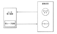
図1は、振動要素と該振動要素に結合されたメータ電子機器を備える従来技術の振動式センサを示す。従来技術の振動式センサは振動要素を振動させるドライバと振動に応じて振動信号を生成するピックオフを含む。振動信号は連続時間又はアナログ信号である。メータ電子機器は振動信号を受信し、1つ以上の流体特性又は流体測定を生成する振動信号を処理する。メータ電子機器は、振動信号の周波数と振幅の両方を決定する。振動信号の周波数及び振幅は、流体の密度を決定すべく、更に処理される。 FIG. 1 shows a prior art vibration sensor comprising a vibration element and meter electronics coupled to the vibration element. Prior art vibration sensors include a driver that vibrates a vibration element and a pickoff that generates a vibration signal in response to the vibration. The vibration signal is a continuous time or analog signal. The meter electronics receives the vibration signal and processes the vibration signal to generate one or more fluid properties or fluid measurements. The meter electronics determines both the frequency and amplitude of the vibration signal. The frequency and amplitude of the vibration signal is further processed to determine the density of the fluid.
従来技術の振動式センサは、閉ループ回路を使用してドライバ用の駆動信号を供給する。駆動信号は一般的に、受信した振動信号に基づく。従来技術の閉ループ回路は、振動信号又は振動信号のパラメータを修正するか、駆動信号内に組み込む。例えば、駆動信号は増幅され、調整され、さもなくば受信した振動信号の修正バージョンである。従って、受信した振動信号は、閉ループ回路が目標周波数に達することを可能にするフィードバックを備える。フィードバックを用いて、閉ループ回路は駆動周波数を漸増的に変更し、目標周波数に達するまで、振動信号を監視する。 Prior art vibratory sensors use a closed loop circuit to provide a driver drive signal. The drive signal is generally based on the received vibration signal. Prior art closed loop circuits modify the vibration signal or parameters of the vibration signal or incorporate it into the drive signal. For example, the drive signal is amplified, adjusted, or otherwise a modified version of the received vibration signal. Thus, the received vibration signal comprises feedback that allows the closed loop circuit to reach the target frequency. Using feedback, the closed loop circuit incrementally changes the drive frequency and monitors the vibration signal until the target frequency is reached.
流体の目標周波数は、駆動信号と振動信号の所望の位相差と関連がある。流体の粘度及び密度のような流体特性は、駆動信号と振動信号の位相差が135°及び45°である場合、周波数から決定される。第1の位相差φ1及び第2の位相差φ2と表示されるこれらの所望の位相差は、半分のパワー即ち3dBに相当する。第1の目標周波数ω1は、第1の位相差φ1が135°である場合の周波数として規定される。第2の目標周波数ω2は、第2の位相差φ2が45°である場合の周波数として規定される。第2の目標周波数ω2にて成される密度の測定は、流体の粘度から独立している。従って、第2の位相差φ2が45°にて成される密度測定は、他の位相差にて成される密度測定よりもより正確である。 The target frequency of the fluid is related to the desired phase difference between the drive signal and the vibration signal. Fluid properties such as fluid viscosity and density are determined from the frequency when the phase difference between the drive and vibration signals is 135 ° and 45 °. These desired phase differences, denoted as the first phase difference φ1 and the second phase difference φ2, correspond to half power, ie 3 dB. The first target frequency ω1 is defined as a frequency when the first phase difference φ1 is 135 °. The second target frequency ω2 is defined as a frequency when the second phase difference φ2 is 45 °. The density measurement made at the second target frequency ω2 is independent of the viscosity of the fluid. Therefore, the density measurement made with the second phase difference φ2 of 45 ° is more accurate than the density measurement made with other phase differences.
閉ループアプローチは一般的に、第2の位相差φ2に達するために、駆動信号周波数をどれほどシフトするかを決定すべく、振動信号の周波数を測定する。測定された周波数を用いて、測定された周波数と位相間の関係は、駆動信号と振動信号の間に45°の位相差があるかを決定するのに用いられる。しかし、流体特性を測定するための閉ループアプローチは、関連する幾つかの問題を有する。例えば、振動信号と駆動信号の所望の位相差を得るために、振動信号の周波数を最初に測定しなければならない。振動信号がノイズに比べて非常に小さいので、これは問題である。その結果、振動信号から周波数を測定するには、フィルタリングが必要である。このフィルタリングは、周波数測定の遅れを引き起こし、これは駆動制御アルゴリズムの不安定性を引き起こす。更に、振動信号中のあらゆる
濾過されないノイズが駆動信号で再生される。駆動信号中のノイズは周波数測定での不正確さと同様に、駆動の不安定性も引き起こす。
従って、閉ループアプローチに関連した周波数測定が不要である振動式センサ用の駆動信号を生成する方法を求めるニーズがある。
The closed loop approach generally measures the frequency of the vibration signal to determine how much to shift the drive signal frequency to reach the second phase difference φ2. Using the measured frequency, the relationship between the measured frequency and phase is used to determine if there is a 45 ° phase difference between the drive signal and the vibration signal. However, the closed loop approach for measuring fluid properties has several associated problems. For example, to obtain the desired phase difference between the vibration signal and the drive signal, the frequency of the vibration signal must first be measured. This is a problem because the vibration signal is very small compared to noise. As a result, filtering is required to measure the frequency from the vibration signal. This filtering causes a delay in frequency measurement, which causes drive control algorithm instability. Furthermore, any unfiltered noise in the vibration signal is reproduced with the drive signal. Noise in the drive signal causes drive instability as well as inaccuracies in frequency measurements.
Accordingly, there is a need for a method for generating a drive signal for a vibration sensor that does not require frequency measurement associated with a closed loop approach.
要約
振動式センサ用の駆動信号を生成する方法が提供される。実施形態に従って、方法は、振動信号を付与するように構成された振動要素を振動させる工程と、受信回路を用いて振動要素から振動信号を受信する工程とを備える。方法は更に、受信回路及び振動要素に連結された駆動回路を用いて、振動要素を振動させる駆動信号を生成する工程と、生成された駆動信号の位相を振動信号の位相と比較する工程を備える。
A method is provided for generating a drive signal for a summary vibration sensor. According to an embodiment, the method comprises oscillating a vibration element configured to provide a vibration signal and receiving the vibration signal from the vibration element using a receiving circuit. The method further comprises generating a drive signal for vibrating the vibration element using a receiving circuit and a drive circuit coupled to the vibration element, and comparing the phase of the generated drive signal with the phase of the vibration signal. .
振動式センサが提供される。実施形態に従って、振動式センサは振動信号を付与するように構成された振動要素と、振動要素から振動信号を受信する受信回路、及び受信回路及び振動要素に連結された駆動回路を備える。駆動回路は、振動要素を振動させる駆動信号を生成し、且つ生成された駆動信号の位相を振動信号の位相と比較するように構成されている。 A vibration sensor is provided. According to an embodiment, the vibration sensor includes a vibration element configured to provide a vibration signal, a reception circuit that receives the vibration signal from the vibration element, and a drive circuit coupled to the reception circuit and the vibration element. The drive circuit is configured to generate a drive signal that vibrates the vibration element, and to compare the phase of the generated drive signal with the phase of the vibration signal.
態様
態様に従って、振動式センサ(5)用の駆動信号を生成する方法(600)は、振動信号を付与するように構成された振動要素(104、510)を振動させる工程と、受信回路(1
34)を用いて振動要素(104、510)から振動信号を受信する工程と、受信回路(134)及び振動要素(104、510)に連結された駆動回路(138)を用いて、振動要素(104、510)を振動させる駆動信号を生成する工程と、生成された駆動信号の位相を振
動信号の位相と比較する工程を備える。
In accordance with an aspect aspect, a method (600) for generating a drive signal for a vibration sensor (5) includes vibrating a vibrating element (104, 510) configured to provide a vibration signal and a receiving circuit (1).
34) to receive the vibration signal from the vibration element (104, 510), and using the receiving circuit (134) and the drive circuit (138) connected to the vibration element (104, 510), the vibration element ( 104, 510) and a step of comparing the phase of the generated drive signal with the phase of the vibration signal.
生成された駆動信号の位相を振動信号の位相と比較する工程は、生成された駆動信号のサンプルを振動信号のサンプルと比較する工程を備えるのが好ましい。
方法(600)は更に、生成された駆動信号のサンプルと振動信号のサンプルの少なくとも1つから、少なくとも1つの周波数成分を除去する工程を備えるのが好ましい。
生成された駆動信号のサンプルを振動信号のサンプルと比較する工程は、生成された駆動信号のサンプルと振動信号のサンプルの相関付けを実行する工程を備えるのが好ましい。
The step of comparing the phase of the generated drive signal with the phase of the vibration signal preferably comprises the step of comparing the sample of the generated drive signal with the sample of the vibration signal.
The method (600) preferably further comprises the step of removing at least one frequency component from at least one of the generated drive signal sample and vibration signal sample.
The step of comparing the generated drive signal sample with the vibration signal sample preferably comprises performing a correlation between the generated drive signal sample and the vibration signal sample.
生成された駆動信号のサンプルを振動信号のサンプルと比較する工程は、生成された駆動信号のサンプルの1つを振動信号のサンプルに接合する工程と、該接合された1つの生成された駆動信号のサンプル及び振動信号のサンプルを、接合されない1つの生成された駆動信号のサンプル及び振動信号のサンプルと掛け合わせる工程を備えるのが好ましい。
生成された駆動信号の位相を振動信号の位相と比較する工程は、生成された駆動信号の位相と振動信号の位相間の測定された位相差φmを決定する工程、及び測定された位相差φmを目標位相差φtと比較し、測定された位相差φmが目標位相差φtにあるかを決定する工程を備えるのが好ましい。
Comparing the generated drive signal sample with the vibration signal sample includes joining one of the generated drive signal samples to the vibration signal sample, and the joined one generated drive signal. Preferably, the step of multiplying the sample of the current signal and the sample of the vibration signal with one sample of the generated drive signal and the sample of the vibration signal that are not joined together.
Comparing the phase of the generated drive signal with the phase of the vibration signal includes determining a measured phase difference φm between the phase of the generated drive signal and the phase of the vibration signal, and the measured phase difference φm Is preferably compared with the target phase difference φt to determine whether the measured phase difference φm is at the target phase difference φt.
方法(600)は更に、測定された位相差φmが目標位相差φtにあるときは、流体の密度を測定する工程を備えるのが好ましい。
方法(600)は更に、生成された駆動信号の位相と振動信号の位相の比較から、コマンド周波数ωを決定する工程と、信号生成器(147c)にコマンド周波数を供給する工程と
、該信号生成器(147c)を用いてコマンド周波数ωにて駆動信号を生成する工程を備え
る。
方法(600)の信号生成器(147c)を用いてコマンド周波数ωにて駆動信号を生成す
る工程は、駆動シンセサイザ(544)を用いて合成された駆動信号を形成する工程と、デジタル/アナログコンバータ(534)を用いて合成された駆動信号を生成された駆動信号
に変換する工程を含むのが好ましい。
The method (600) preferably further comprises the step of measuring the density of the fluid when the measured phase difference φm is at the target phase difference φt.
The method (600) further includes determining a command frequency ω from comparing the phase of the generated drive signal and the phase of the vibration signal, supplying the command frequency to the signal generator (147c), and generating the signal And a step of generating a drive signal at the command frequency ω using the device (147c).
The method of generating a drive signal at the command frequency ω using the signal generator (147c) of the method (600) includes forming a combined drive signal using the drive synthesizer (544), and a digital / analog converter. Preferably, the method includes a step of converting the drive signal synthesized using (534) into the generated drive signal.
態様に従って、振動式センサ(5)は振動信号を付与するように構成された振動要素(1
04、510)、振動要素(104)から振動信号を受信する受信回路(134)、受信回路(134)及び振動要素(104)に連結された駆動回路(138)を備え、駆動回路(138)
は振動要素(104、510)を振動させる駆動信号を生成し、且つ生成された駆動信号の位相と振動信号の位相とを比較するように構成されている。
According to an embodiment, the vibration sensor (5) is a vibration element (1) configured to provide a vibration signal.
04, 510), a reception circuit (134) for receiving a vibration signal from the vibration element (104), a reception circuit (134), and a drive circuit (138) connected to the vibration element (104), and a drive circuit (138).
Is configured to generate a drive signal for vibrating the vibration element (104, 510), and to compare the phase of the generated drive signal with the phase of the vibration signal.
駆動回路(138)は、生成された駆動信号のサンプルと振動信号のサンプルを比較するように構成されているのが好ましい。
駆動回路(138)は更に、生成された駆動信号のサンプルと振動信号のサンプルの少なくとも1つから、少なくとも1つの周波数成分を除去するように構成されるのが好ましい。
駆動回路(138)は更に、生成された駆動信号のサンプルと振動信号のサンプルの相関付けを実行するように構成されているのが好ましい。
The drive circuit (138) is preferably configured to compare the generated sample of the drive signal with the sample of the vibration signal.
The drive circuit (138) is further preferably configured to remove at least one frequency component from at least one of the generated drive signal sample and vibration signal sample.
The drive circuit (138) is preferably further configured to perform a correlation of the generated drive signal samples and vibration signal samples.
駆動回路(138)は更に、生成された駆動信号のサンプルの1つを振動信号のサンプルに接合し、該接合された1つの生成された駆動信号のサンプル及び振動信号のサンプルを、接合されない1つの生成された駆動信号のサンプル及び振動信号のサンプルと掛け合わせるように構成されているのが好ましい。
駆動回路(138)は、生成された駆動信号の位相と振動信号の位相間の測定された位相差φmを決定し、及び測定された位相差φmを目標位相差φtと比較し、測定された位相差φmが目標位相差φtにあるかを決定するように構成されているのが好ましい。
The drive circuit (138) further joins one of the generated drive signal samples to the vibration signal sample, and the joined one generated drive signal sample and vibration signal sample are not joined 1 Preferably, it is configured to multiply the two generated drive signal samples and vibration signal samples.
The drive circuit (138) determines the measured phase difference φm between the phase of the generated drive signal and the phase of the vibration signal, and compares the measured phase difference φm with the target phase difference φt to be measured. It is preferably configured to determine whether the phase difference φm is at the target phase difference φt.
駆動回路(138)は更に、測定された位相差φmが目標位相差φtにあるときは、流体の密度を測定するように構成されているのが好ましい。
駆動回路(138)は、位相検知器(147b、542)と信号生成器(147c)を備え、該位相検知器(147b)は、生成された駆動信号の位相及び振動信号の位相の比較からコマ
ンド周波数ωを決定し、該コマンド周波数ωを信号生成器(147c)に供給するように構
成され、信号生成器(147c)はコマンド周波数ωにて駆動信号を生成するように構成さ
れているのが好ましい。
信号生成器(147c)は、合成された駆動信号を形成するように構成された駆動シンセ
サイザ(544)と、合成された駆動信号を生成された駆動信号に変換するように構成されたデジタル/アナログコンバータ(534)を備えるのが好ましい。
The drive circuit (138) is further preferably configured to measure the density of the fluid when the measured phase difference φm is at the target phase difference φt.
The drive circuit (138) includes a phase detector (147b, 542) and a signal generator (147c). The phase detector (147b) receives a command from a comparison of the phase of the generated drive signal and the phase of the vibration signal. The frequency ω is determined, and the command frequency ω is configured to be supplied to the signal generator (147c). The signal generator (147c) is configured to generate a drive signal at the command frequency ω. preferable.
The signal generator (147c) includes a drive synthesizer (544) configured to form a combined drive signal, and a digital / analog configured to convert the combined drive signal into a generated drive signal. A converter (534) is preferably provided.
同じ符号は全ての図面上の同じ要素を表す。図面は必ずしも縮尺通りではないことは理解されるべきである。
図2−図6及び以下の記述は特定の例を記載して、振動式センサ用の駆動信号を生成する方法の実施形態の最良のモードを作り使用する方法を当業者に開示する。進歩性を有する原理を開示する目的で、いくつかの従来の態様は単純化されたか省略された。
当業者は、これらの例示から本発明の範囲内にある変形例を理解するだろう。当業者は、下記に述べられた特徴が種々の方法で組み合わされて、振動式センサ用の駆動信号を生成する多数の変形例を形成することを理解するだろう。その結果、本発明は、下記に述べられた特定の例にではなく特許請求の範囲とそれらの等価物によってのみ限定される。
2-6 and the following description describe specific examples and disclose to those skilled in the art how to make and use the best mode of embodiment of a method for generating a drive signal for a vibratory sensor. For the purpose of disclosing the inventive principle, some conventional aspects have been simplified or omitted.
Those skilled in the art will appreciate variations from these examples that fall within the scope of the invention. Those skilled in the art will appreciate that the features described below can be combined in various ways to form numerous variations that generate a drive signal for a vibratory sensor. As a result, the invention is not limited to the specific examples described below, but only by the claims and their equivalents.
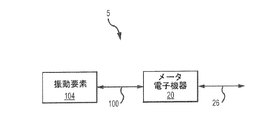
図2は、実施形態に従った振動式センサ5を示す。振動式センサ5は振動要素104及びメータ電子機器20を備え、該振動要素104はリード100によってメータ電子機器20に連結される。幾つかの実施形態では、振動式センサ5は振動式の歯センサ又はフォーク密度センサを含む(図3及びそれに伴う記載を参照)。しかし、他の振動式センサも考えられ、それは記載と特許請求の範囲内である。
FIG. 2 shows a
振動式センサ5は、特性を明らかにすべき流体内に、少なくとも部分的に浸けられる。流体は液体又はガスを含む。或いは、流体は混入ガス、混入固体、多数液体又はそれらの組み合わせを含む液体のような多相流体である。幾つかの代表的な流体は、セメントスラリー、石油生成物などを含む。振動式センサ5は、パイプ又は導管、タンク、コンテナ又は他の流体の容器内に取り付けられる。振動式センサ5はまた、流体流れを向けるマニホールド又は同様の構造に取り付けられる。しかし他の取付け構成も考えられ、これは記載と特許請求の範囲内である。
The
振動式センサ5は流体測定を提供すべく作動する。振動式センサ5は、流れ流体又は非流れ流体を含む流体の、流体密度及び流体粘性の1つ以上を含む流体測定を提供する。振動式センサ5は、流体の質量流量、体積流量及び/又は流体温度を含む流体測定を提供す
る。このリストは網羅したものでなく、振動式センサ5は他の流体特性を測定し、決定し得る。
The
メータ電子機器20はリード100を介して振動要素104に電力を供給する。メータ電子機器20はリード100を介して振動要素104の動作を制御する。例えば、メータ電子機器20は駆動信号を生成し、該駆動信号を振動要素104に供給し、該振動要素104は生成された駆動信号を用いて1以上の振動部品に振動を生成する。生成された駆動信号は、振動要素104の振幅及び周波数を制御することができる。生成された駆動信号はまた、振動期間及び/又は振動タイミングを制御することができる。
The
メータ電子機器20はまた、リード100を介して振動要素104から振動信号を受信する。メータ電子機器20は振動信号を処理して例えば密度測定を生成する。メータ電子機器20は振動要素104から受信した振動信号を処理して、信号の周波数を決定する。更に又は加えて、メータ電子機器20は振動信号を処理して、流体の他の特性を決定し、該他の特性は例えば粘度又は例えば流体の流速を決定するために処理される信号間の位相シフトである。他の振動応答特性及び/又は流体測定が考えられ、それらは記載と特許請
求の範囲内である。
メータ電子機器20は更に、通信リンク26に連結される。メータ電子機器20は、通信リンク26を介して振動信号を通信する。メータ電子機器20はまた、受信した振動信号を処理して、測定値を生成し、通信リンク26を介して該測定値を通信する。
更に、メータ電子機器20は、通信リンク26を介して情報を得ることができる。
例えば、メータ電子機器20はコマンド、更新、作動値の変更及び/又はプログラムの更
新を通信リンク26を介して受信する。
Further, the
For example,
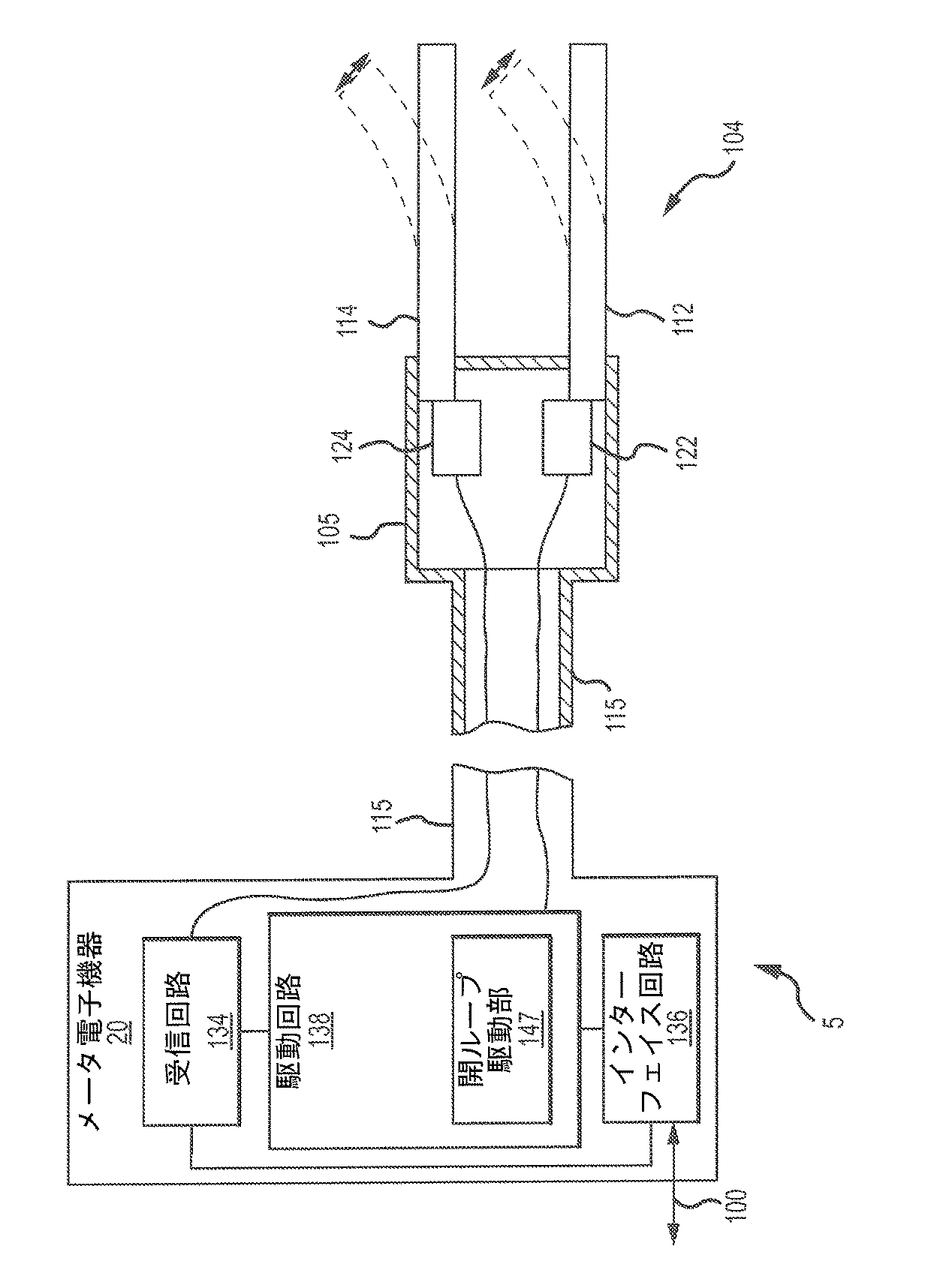
図3は、実施形態に従った振動式センサ5を示す。実施形態に示すように、メータ電子機器20はシャフト115によって振動要素104に連結される。シャフト115は任意の所望の長さである。シャフト115は、少なくとも部分的に中空である。ワイヤ又は他の導体はシャフト115を通ってメータ電子機器20と振動要素104の間を延びる。メータ電子機器20は、受信回路134、インターフェイス回路136、及び駆動回路138のような回路部品を含む。示された実施形態にて、受信回路134及び駆動回路138は振動要素104のリードに直に連結される。或いは、メータ電子機器20は振動要素104から分離した部品又はデバイスを備え、受信回路134及び駆動回路138はリード100を介して振動要素104に連結される。
FIG. 3 shows a
示された実施形態にて、振動式センサ5の振動要素104は同調フォーク構造を備え、振動要素104は市区定される流体に少なくとも部分的に浸される。振動要素104は、パイプ、導管、タンク、容器、マニホールドのような他の構造又は他の流体を取り扱う構造に固定されるハウジング105を含む。振動要素104が少なくとも部分的に晒されている間は、ハウジング105は振動要素104を保持する。従って、振動要素104は流体内に浸されるように構成される。
In the embodiment shown, the vibrating
実施形態に示される振動要素104は、少なくとも部分的に流体内に延びるように構成された第1歯112及び第2歯114を含む。第1歯112及び第2歯114は所望の断面形状を有する長手部材を備える。第1歯112及び第2歯114は、本来は可撓性又は弾性である。振動式センサ5は更に、圧電水晶要素を備える対応した第1ピエゾ要素122及び第2ピエゾ要素124を含む。第1ピエゾ要素122及び第2ピエゾ要素124は夫々第1歯112及び第2歯114の隣に位置する。第1ピエゾ要素122及び第2ピエゾ要素124は、第1歯112及び第2歯114に接触し、機械的に相互作用する。
The vibrating
第1ピエゾ要素122は第1歯112の少なくとも一部と接する。第1ピエゾ要素122はまた、駆動回路138に電気的に連結される。駆動回路138は生成された駆動信号を第1ピエゾ要素122に供給する。第1ピエゾ要素122は生成された駆動信号を受けたときに、膨れ縮まる。その結果、第1ピエゾ要素122は交互に撓み、第1歯112を振動運動にて側方から側方に移動させ(点線を参照)、周期的に往復する方法で流体を乱す。
The first
第2ピエゾ要素124は、受信回路134に結合するとして示され、流体内で第2歯114の撓みに対応して振動信号を生成する。第2歯114の動きにより、第2ピエゾ要素124によって電気的振動が生成される。第2ピエゾ要素124は、振動信号をメータ電子機器20に送信する。メータ電子機器20はインターフェイス回路136を含む。インターフェイス回路136は外部デバイスと通信するように構成されている。
インターフェイス回路136は振動測定信号を通信し、1つ以上の外部デバイスに決定された流体特性を伝える。メータ電子機器20は、振動信号周波数及び振動信号の振動信号振幅のような振動信号特性をインターフェイス回路136を介して送信することができる。メータ電子機器20は、インターフェイス回路136を介して、とりわけ流体の密度及び/又は粘性のような流体測定を送信する。他の流体の測定も考えられ、それらは記載
と特許請求の範囲内である。
更に、インターフェイス回路136は、例えば測定値を生成するためのコマンド及びデータを含む通信を外部デバイスから受信する。いくつかの実施形態では、受信回路134は、駆動回路138に連結されて、振動信号を駆動回路138に供給する
The second
Furthermore, the
駆動回路138は、振動要素104用の駆動信号を生成する。駆動回路138は、生成
された駆動信号の特性を修正する。周囲の流体によって影響を受けるように、振動要素104は略共振振動数に維持される。駆動回路138は開ループ駆動部147を含む。開ループ駆動部147は駆動回路138によって用いられて、駆動信号を生成し、生成された駆動信号を振動要素104に(例えば、第1ピエゾ要素122に)供給する。幾つかの実施形態では、開ループ駆動部147は、最初の周波数ω0で開始して、目標位相差φtに達
する駆動信号を生成する。開ループ駆動部147は振動信号からのフィードバックに基づいて作動しない。従って、開ループ駆動部147は、下記により詳細に記述されるように、振動信号を濾過することによりノイズの無い生成された駆動信号を時間遅れなしで供給する。
The
図4は、振動式センサ5のブロック図を示し、駆動回路138をより詳細に表す。振動式センサは駆動回路138とともに示される。受信回路134及びインターフェイス回路136は明瞭化のために示されない。駆動回路138は開ループ駆動部147に連結されたアナログ入力フィルタ138a及びアナログ出力フィルタ138bを含む。アナログ入力フィルタ138aは振動信号を濾過し、アナログ出力フィルタ138bは生成された駆動信号を濾過する。
開ループ駆動部147は、位相検知器147bに連結されるアナログ/デジタル変換器147aを含む。位相検知器147bは、信号生成器147cに連結される。
更に、第1ピエゾ要素122と第2ピエゾ要素124を含む振動要素104が示される。開ループ駆動部147は、信号をサンプリングし、処理し、生成する1本以上のコード又はプログラムを実行するように構成されるデジタル信号プロセッサで実行され得る。更に又は或いは、開ループ駆動部147はデジタル信号プロセッサなどに連結された電子回路で実行され得る。
FIG. 4 shows a block diagram of the
The open loop driver 147 includes an analog / digital converter 147a coupled to the
Further shown is a vibrating
第1ピエゾ要素122によって提供される振動信号は、アナログ入力フィルタ138a
に送信される。アナログ入力フィルタ138aは、振動信号がアナログ/デジタル変換器147aによってサンプリングされる前に、振動信号を濾過する。示された実施形態では、
アナログ入力フィルタ138aはカットオフ周波数を有するローパスフィルタを備え、あ
らゆる適切なローパスフィルタが用いられ得るが、該カットオフ周波数は開ループ駆動部147のサンプリング速度の約半分である。ローパスフィルタは演算増幅器フィルタのような分配型又はディスクリートのあらゆる適切な部品が用いられるが、誘導子、コンデンサ及び抵抗器のような受動素子によって提供される。
The vibration signal provided by the first
Sent to. The
The
アナログ/デジタル変換器147aは濾過された振動信号をサンプリングして、振動信号のサンプルを形成することが出来る。アナログ/デジタル変換器147aは第2チャンネルを介して生成された駆動信号をサンプリングすることが出来る。該サンプリングはあらゆる適切なサンプリング方法である。理解されるように、アナログ/デジタル変換器147aによってサンプリングされた生成された駆動信号は振動信号に関するノイズを有さない。生成された駆動信号は位相検知器147bに付与される。
The analog / digital converter 147a can sample the filtered vibration signal to form a sample of the vibration signal. The analog / digital converter 147a can sample the drive signal generated through the second channel. The sampling is any suitable sampling method. As will be appreciated, the generated drive signal sampled by the analog / digital converter 147a has no noise associated with the vibration signal. The generated drive signal is applied to the
位相検知器147bはサンプリングされた振動信号の位相と生成された駆動信号の位相
を比較する。位相検知器147bは、図5に関して下記により詳細に記述されるように、
2つの信号間の位相差を検知する信号をサンプリングし、処理し、生成する1以上のコードあるいはプログラムを実行するように構成されたプロセッサである。図4の実施形態に言及して、比較により振動信号のサンプルと生成された駆動信号のサンプル間の測定された位相差φmが付与される。
The
A processor configured to execute one or more codes or programs that sample, process, and generate a signal that senses a phase difference between two signals. Referring to the embodiment of FIG. 4, the comparison gives a measured phase difference φm between the sample of the vibration signal and the sample of the generated drive signal.
測定された位相差φmは目標位相差φtと比較される。目標位相差φtは振動信号と生成された駆動信号の所望の位相差である。実施形態にて、目標位相差φtが約45°であれば、測定された位相差φmと目標位相差φtとの差は、測定された位相差φmが45°
と同じ又は約45°であれば、ゼロである。しかし、代替の実施形態では、あらゆる適切な目標位相差φtが用いられ得る。測定された位相差φmと目標位相差φtとの比較を用いて、位相検知器147bはコマンド周波数ωを生成することが出来る。
The measured phase difference φm is compared with the target phase difference φt. The target phase difference φt is a desired phase difference between the vibration signal and the generated drive signal. In the embodiment, if the target phase difference φt is about 45 °, the difference between the measured phase difference φm and the target phase difference φt is such that the measured phase difference φm is 45 °.
Is equal to or about 45 °, it is zero. However, in alternative embodiments, any suitable target phase difference φt can be used. Using the comparison between the measured phase difference φm and the target phase difference φt, the
コマンド周波数ωは駆動信号を生成するのに用いられる。更に又は或いは、測定された位相差φmと目標位相差φt間の比較からは決定されない最初の周波数ω0が用いられる。最初の周波数ω0は、最初に生成された駆動信号を形成するのに用いられる予め選択された周波数である。最初に生成された駆動信号が上記の如く、サンプリングされ、サンプリングされた振動信号と比較される。最初に生成された駆動信号のサンプルと振動信号のサンプルの比較は、コマンド周波数ωを生成するのに用いられる。あらゆる適切な単位も使用することができるが、コマンド周波数ωと最初の周波数ω0は、ラジアン/秒の単位
を有する。コマンド周波数ω又は最初の周波数ω0は、信号生成器147cに供給される
。
The command frequency ω is used to generate a drive signal. Additionally or alternatively, an initial frequency ω 0 is used that is not determined from a comparison between the measured phase difference φm and the target phase difference φt. The initial frequency ω 0 is a preselected frequency that is used to form the initially generated drive signal. The initially generated drive signal is sampled as described above and compared to the sampled vibration signal. The comparison of the first generated drive signal sample and the vibration signal sample is used to generate the command frequency ω. Any suitable unit can be used, but the command frequency ω and the initial frequency ω 0 have units of radians / second. The command frequency ω or the initial frequency ω 0 is supplied to the
信号生成器147cは位相検知器147bからコマンド周波数ωを受信し、該コマンド周波数ωと同じ周波数を有する生成された駆動信号を付与する。前記の如く、生成された駆動信号はアナログ/デジタル変換器147aに送信される。生成された駆動信号はまた、アナログ出力フィルタ138bを介して第2ピエゾ要素124に送信される。更に又は或い
は、生成された駆動信号は他の実施形態の他の部品に送信される。従って、これら及び他の実施形態にて、生成された駆動信号は、以下により詳細に記載する如く、測定された位相差φmと目標位相差φtとの差から決定される。
The
図5は、実施形態に従った振動式センサ5のブロック図500を示す。ブロック図500は振動要素510を含む。振動要素510はドライバ510a及びピックオフ510bを含む。ブロック図500は、更にピックオフ510bに連結される振動利得部520を含
む。振動利得部520は、符号復号器(CODEC)ブロック530にあるアナログ/デジタル変換器532に連結される。アナログ/デジタル変換器532は、デジタル信号プロセッサ(DSP)ブロック540内の位相検知器542に連結される。DSPブロック540は、さらに
位相検知器542から信号を受信する駆動シンセサイザ544を含む。駆動シンセサイザ544は、駆動利得部550に連結されるデジタル/アナログ変換器534に連結される
。駆動利得部550は、駆動ステージ560及びアナログ/デジタル変換器532に連結
される。駆動利得部550は、符号復号器ブロック530によって提供される、生成された駆動信号を増幅することができる。
FIG. 5 shows a block diagram 500 of the
あらゆる構成も用いることができるが、符号復号器ブロック530は2ウェイのコンバーターとして示される。示されるように、符号復号器ブロック530中のアナログ/デジ
タル変換器532は、振動利得部520から振動信号を受信する。代替の実施形態では、振動信号は、ピックオフ510bからアナログ/デジタル変換器532に直接提供することができる。アナログ/デジタル変換器532は、サンプリングされた振動信号を生成する
サンプリングレート及び分解能を以て、連続時間信号であり得る振動信号をサンプリングする。
アナログ/デジタル変換器532は、サンプリングの前に振動信号から望ましくない周
波数成分を取り除く、アンチエイリアシング(anti-aliasing)フィルタを含む。
Although any configuration can be used, the
The analog /
アナログ/デジタル変換器532は、さらに駆動利得部550によって提供される、生
成された駆動信号をサンプリングする。あらゆる適切な信号も提供されるが、駆動利得部550から生成された駆動信号は連続時間信号になる。振動信号と同様に、アナログ/デ
ジタル変換器532は、適切なサンプリングレート及び分解能を以て、生成された駆動信号をサンプリングすることができる。アナログ/デジタル変換器532はまた、サンプリ
ングの前に、生成された駆動信号からあらゆる望ましくない周波数成分を取り除く、アン
チエイリアシングフィルタを含む。サンプリングされた振動信号及びサンプリングされた生成された駆動信号は、DSPブロック540中の位相検知器542に提供される。位相検
知器542は、下記に記載するように、サンプリングされた振動信号をサンプリングされた生成された駆動信号と比較して、測定された位相差φmを決定する。
The analog /
示された実施形態では、位相検知器542は、サンプリングされた信号を関連付けることにより、サンプリングされた振動信号及びサンプリングされた生成された駆動信号の間の測定された位相差φmを決定することができる。例えば、信号をサンプリングし、処理
し、生成する1以上のコード又はプログラムが、圧縮化(decimation)及び他のDSP機能に
加えて、変換を実行して、測定された位相差φmを決定する。
生成された駆動信号及び振動信号は、次の方程式[1]及び[2]によって複素平面中で表わされる。
The generated drive signal and vibration signal are represented in the complex plane by the following equations [1] and [2].
Zgsd(κ)関数は生成された駆動信号の複素表現であり、Zvs(κ)関数は振動信号の複素表現である。exp(―j( 2ωκ+ψvs))項は、整数κが周波数ωと乗算されることを含んで、周波数成分を表す。圧縮化又は他のフィルタリングが、周波数成分を除去するのに用いられ得る。従って、周波数成分の無い複素表現は方程式[3]及び[4]として表される。
着する。
1つの関数が共役しなかった(例えば、非共役)ことが判るだろう。方程式[5]から生成
された駆動信号と振動信号の間の測定された位相差φmは、
![]()
前記では、如何に測定された位相差φmが決定されるかを示す典型的な実施形態が示さ
れる。理解されるように、異なる実施形態の位相検知器542は、サンプリングされた振動信号及びサンプリングされた生成された駆動信号の間の測定された位相差φmを決定す
ることが出来る。図6について以下により詳細に説明されるように、測定された位相差φmはコマンド周波数ωを決定するのに用いられる。また、図5を参照してコマンド周波数
ωは駆動シンセサイザ544に付与される。
It can be seen that one function was not conjugated (eg unconjugated). The measured phase difference φm between the drive signal and vibration signal generated from equation [5] is
![]()
In the above, an exemplary embodiment is shown which shows how the measured phase difference φm is determined. As will be appreciated, different embodiments of the
駆動シンセサイザ544は、1以上のコード又はプログラムを実行し、コマンド周波数
ωを受信して合成された駆動信号を付与するプロセッサである。合成された駆動信号は単純な正弦波信号の離散的表現になり得る。例えば、合成された駆動信号は、単純な正弦波信号に相当するエンベロープを備えたインパルス列になり得る。更に又は或いは、駆動シンセサイザ544は、デジタル回路、フィールドプログラマブルゲートアレイなど(FPGA)であり得る。
例えば、デジタル回路は、コマンド周波数ωに相当する振幅を備えた直流(DC)電圧信号を受け取る。代替の実施形態では、駆動シンセサイザは電圧信号(例えば直流など)を受け取り、生成された駆動信号に電圧信号に比例するコマンド周波数ωを供給する。
The drive synthesizer 544 is a processor that executes one or more codes or programs, receives the command frequency ω, and applies a synthesized drive signal. The synthesized drive signal can be a discrete representation of a simple sinusoidal signal. For example, the synthesized drive signal can be an impulse train with an envelope corresponding to a simple sine wave signal. Additionally or alternatively, the drive synthesizer 544 can be a digital circuit, a field programmable gate array, etc. (FPGA).
For example, the digital circuit receives a direct current (DC) voltage signal having an amplitude corresponding to the command frequency ω. In an alternative embodiment, the drive synthesizer receives a voltage signal (eg, direct current) and provides a command frequency ω proportional to the voltage signal to the generated drive signal.
示された実施形態では、駆動シンセサイザ544はデジタル/アナログ変換器534に
合成された駆動信号を供給する。デジタル/アナログ変換器534は合成された駆動信号
を生成された駆動信号に変換する。あらゆる適切なデジタル/アナログ変換器534も使
用され得るが、デジタル/アナログ変換器534は、例えば、インパルス列を階段状の正
弦波波形に変換するゼロ次ホールドであり得る。駆動シンセサイザ544が以前に記載されたデジタル回路かFPGAであるような代替の実施形態の場合、デジタル/アナログ変換器
534は必要ではない。そのような実施形態では、生成された駆動信号は、デジタル/ア
ナログ変換なしで提供することができる。これら及び他の実施形態では、生成された駆動信号は、コマンド周波数ωの、あるいはω周りの単純な正弦波信号になり得る。代替の実施形態では、生成された駆動信号は、1以上の周波数成分で構成されることができる。示された実施形態では、生成された駆動信号は、駆動利得部550に送られる。
In the illustrated embodiment, the drive synthesizer 544 provides the combined drive signal to the digital /
駆動利得部550は生成された駆動信号を増幅し、アナログ/デジタル変換器532及
び駆動ステージ560に増幅された生成された駆動信号を供給する。駆動利得部550及び駆動ステージ560は、所望の波形を達成するように、生成された駆動信号を修正することができる。例えば、駆動利得部550は、ドライバ510aに利用可能な電力を超え
るように、生成された駆動信号を増幅することができる。従って、生成された駆動信号が時間が連続した正弦波信号である実施形態にて、ドライバ510aに供給される、生成さ
れた駆動信号は台形形状を有する。更に又は或いは、生成された駆動信号には三角形波形、異なる波形の一続きのような他の形を有する。
これら及び他の波形は、下記により詳細に説明されるように、測定された位相差φmから決定されたコマンド周波数を用いて形成され得る。
The driving
These and other waveforms can be formed using a command frequency determined from the measured phase difference φm, as described in more detail below.
図6は、実施形態に従って、駆動信号を生成する方法600を示す。方法600はステップ610から開始する。ステップ610で、振動は第2歯114によって測定される。第2歯114は流体内の振動により振動する。振動は、コマンド周波数ω或いは最初の周波数ω0で振動する第1歯112により流体内に存在する。第2ピエゾ要素124はアナログ入力フィルタ138aに振動信号を送信する。アナログ入力フィルタ138aは、振動信号を濾過して、ノイズを削除し、かつ振動信号の帯域幅を制限する。濾過された振動信号は、アナログ/デジタル変換器147a、532に送信される。信号生成器147cから
の生成された駆動信号も、アナログ/デジタル変換器147a、532に送信される。
FIG. 6 illustrates a
ステップ620で、振動信号及び生成された駆動信号はアナログ/デジタル変換器14
7a、532によってサンプリングされる。サンプリングは、振動信号及び生成された駆
動信号を数列に変換するあらゆる適切なサンプリング方法であり、例えばバイナリフォーマットである。サンプリングはあらゆる適切なサンプリングレート及びビット分解能でも行うことができる。
ステップ630で、サンプリングされた振動信号の位相及びサンプリングされた生成された駆動信号の位相の間の測定された位相差φmは、位相検知器147bによって決定される。測定された位相差φmは度の単位を有する角度であるが、ラジアンのような他の単位
も他の実施形態にて用いられる。或いは、位相差ではなく時間差が用いられる。
In
7a, 532 for sampling. Sampling is any suitable sampling method that converts the vibration signal and the generated drive signal into a sequence of numbers, for example in binary format. Sampling can be done at any suitable sampling rate and bit resolution.
At
ステップ640で、測定された位相差φmは目標位相差φtと比較される。上記に記載
の実施形態にて、目標位相差φtは45°である。比較結果が測定された位相差φmが目
標位相差φtと同じであることを示せば、方法600はステップ660にてコマンド周波数ω又は最初の周波数ω0と同じ駆動信号を生成し続ける。測定された位相差φmが目標
位相差φtと同じでなければ、ステップ650にてコマンド周波数ωが決定される。
At
ステップ650で、コマンド周波数ωは測定された位相差φmから決定される。例えば
、上記に記載の実施形態にて、測定された位相差φmが目標位相差φtよりも小さければ
、コマンド周波数ωが増加される。しかし、代替の実施形態において、コマンド周波数ωは代替の手段を用いて測定された位相差φmから決定される。これらの又は他の実施形態
において、コマンド周波数ωはステップ660にて駆動信号を生成するのに用いられる。
In
ステップ660で、信号生成器147cはコマンド周波数ωで生成された駆動信号を形
成する。実施形態では、信号生成器147cは、駆動シンセサイザ544及びデジタル/アナログ変換器534から構成される。或いは、信号生成器147cはデジタル回路、FPGA
などで構成される。図5に関して記載された実施形態では、生成された駆動信号は、駆動シンセサイザ544によって提供された駆動信号から合成される。これら及び他の実施形態では、他の適切な信号も提供され得るが、生成された駆動信号は単一の周波数を備えた正弦波の駆動信号になる。
In
Etc. In the embodiment described with respect to FIG. 5, the generated drive signal is synthesized from the drive signal provided by the drive synthesizer 544. In these and other embodiments, other suitable signals may be provided, but the generated drive signal will be a sinusoidal drive signal with a single frequency.
生成された駆動信号は振動要素104、510を振動させるために使用される。図5に示されるように、生成された駆動信号は駆動利得部550及び駆動ステージ560に提供される。駆動利得部550及び駆動ステージ560は、生成された駆動信号を修正し、ドライバ510aへ提供する。しかし、生成された駆動信号は、他の手段によっても、振動
要素104、510に提供することができる。例えば、生成された駆動信号は、ドライバ510aに直接提供することができる。生成された駆動信号もサンプリングされ、測定さ
れる。例えば、図6に示すように、ステップ660はまた、生成された駆動信号がサンプリングされるステップ620に生成された駆動信号を返す。
The generated drive signal is used to vibrate the
動作では、位相検知器147bは、信号生成器147cにコマンド周波数ωを送信することができる。幾つかの実施形態では、駆動回路138はコマンド周波数ωで且つ開ループの方法で振動要素104(例えば、第1歯112、ドライバ510a)を振動させ、目標位
相差φtに達する。目標位相差φtは流体密度を正確に測定すべく、45°である。しかし、代替の実施形態では、目標位相差φtは他の値である。
In operation,
方法600及び振動式センサ5は生成された駆動信号を提供することができる。例えば、生成された駆動信号は、コマンド周波数ωで信号生成器147cによって提供され得る
。
実施形態では、信号生成器147cは駆動シンセサイザ544及びデジタル/アナログ変換器534で構成される。コマンド周波数ωは、振動信号と生成された駆動信号の間の測定された位相差φmから決定される。測定された位相差φmは位相検知器147b、542を
使用して決定される。
The
In the embodiment, the
理解されるように、振動信号の周波数は測定されず、又は生成された駆動信号の周波数とは比較されない。その代り、振動信号の位相及び生成された駆動信号の位相は、信号をサンプリングし、処理し、生成する1以上のコード又はプログラムを用いて決定される。例えば、前記の実施形態によれば、サンプリングされた振動信号及びサンプリングされた駆動信号は、周波数成分無しで、接合され関連付けられて、測定された位相差φmを決定
する。従って、振動信号と生成された駆動信号の間の測定された位相差φmは、従来技術
の振動計に関する遅延が無く決定される。更に、信号生成器147cは振動信号に関する
ノイズ無しで生成された駆動信号を付与する。例えば、前記の実施形態に記載した如く、測定された位相差φmを決定する前に、位相検知器542はサンプリングされた振動信号
及び生成された駆動信号の周波数成分を除去する。
As will be appreciated, the frequency of the vibration signal is not measured or compared to the frequency of the generated drive signal. Instead, the phase of the vibration signal and the phase of the generated drive signal are determined using one or more codes or programs that sample, process and generate the signal. For example, according to the embodiment described above, the sampled vibration signal and the sampled drive signal are joined and associated without a frequency component to determine the measured phase difference φm. Accordingly, the measured phase difference φm between the vibration signal and the generated drive signal is determined without the delay associated with the prior art vibrometer. Further, the
従って、生成された駆動信号は、振動信号からのノイズ、又は従来技術に関する時間遅延を含まない。生成された駆動信号は振動信号に関するノイズが無いから、密度測定は更に正確である。更に、従来技術のフィルタリングに関する時間遅延が無いから、生成された駆動信号は更に安定する。これら及び他の利点は、代替の実施形態と同様に、方法600及び振動式センサ5に関して得られる。
Thus, the generated drive signal does not include noise from the vibration signal or time delay with respect to the prior art. Since the generated drive signal is free of noise with respect to the vibration signal, the density measurement is more accurate. Furthermore, since there is no time delay associated with prior art filtering, the generated drive signal is more stable. These and other advantages are obtained with the
上記の実施形態の詳細な記述は、本発明の範囲内にある発明者によって熟考された全ての実施形態の完全な記述ではない。実際に当業者は、さらに実施形態を作成するために上記実施形態のある要素が種々に組み合わせられるかもしれないし除去されるかもしれないことを認識している、そしてそのような、さらなる実施形態は現在の記述の範囲及び開示の範囲内にある。現在の記述の範囲及び開示の範囲内にある追加の実施形態を作成するために、上記実施形態の全部或いは一部が組み合わせられるかもしれないことも当業者には明白である。
従って、特定の実施形態が説明の目的のためにここに記述されているが、当業者が認識するように、様々な等価な修正は現在の記述の範囲内で可能である。ここに提供される開示は、振動式センサの駆動信号を生成する他の方法に適用可能であり、上記に記載され添付の図面に示された実施形態だけではない。従って、上記の実施形態の範囲は、添付の特許請求の範囲から決定されるべきである。
The above detailed description of the embodiments is not a complete description of all the embodiments contemplated by the inventors within the scope of the present invention. Indeed, those skilled in the art will recognize that certain elements of the above embodiments may be variously combined and removed to create further embodiments, and such further embodiments are Within the scope of the current description and disclosure. It will be apparent to those skilled in the art that all or part of the above embodiments may be combined to create additional embodiments that are within the scope of the current description and disclosure.
Thus, although particular embodiments are described herein for purposes of illustration, various equivalent modifications are possible within the scope of the current description, as those skilled in the art will recognize. The disclosure provided herein is applicable to other methods of generating drive signals for vibratory sensors and is not limited to the embodiments described above and shown in the accompanying drawings. Accordingly, the scope of the above embodiments should be determined from the appended claims.
Claims (18)
振動信号を付与するように構成された振動要素(104、510)を振動させる工程と、受信回路(134)を用いて前記振動要素(104、510)から振動信号を受信する工程と、
前記受信回路(134)及び前記振動要素(104、510)に連結された駆動回路(138)を用いて、前記振動要素(104、510)を振動させる駆動信号を生成する工程と、
生成された駆動信号の位相を振動信号の位相と比較する工程を備える、方法(600)。 A method (600) for generating a drive signal for a vibration sensor (5) comprising:
Vibrating a vibration element (104, 510) configured to provide a vibration signal; receiving a vibration signal from the vibration element (104, 510) using a receiving circuit (134);
Generating a driving signal for vibrating the vibrating element (104, 510) using a driving circuit (138) coupled to the receiving circuit (134) and the vibrating element (104, 510);
Comparing the phase of the generated drive signal with the phase of the vibration signal (600).
00)。 The method of claim 1, wherein comparing the phase of the generated drive signal with the phase of a vibration signal comprises comparing a sample of the generated drive signal with a sample of a vibration signal.
00).
生成された駆動信号のサンプルの1つを振動信号のサンプルに接合する工程と、
該接合された1つの生成された駆動信号のサンプル及び振動信号のサンプルを、接合されない1つの生成された駆動信号のサンプル及び振動信号のサンプルと掛け合わせる工程を備える、請求項2に記載の方法(600)。 Comparing the generated drive signal sample with a vibration signal sample comprises:
Joining one of the generated drive signal samples to the vibration signal sample;
3. The method of claim 2, comprising the step of multiplying the spliced one generated drive signal sample and vibration signal sample with one spliced one generated drive signal sample and vibration signal sample. (600).
生成された駆動信号の位相と振動信号の位相間の測定された位相差φmを決定する工程、及び
測定された位相差φmを目標位相差φtと比較し、測定された位相差φmが目標位相差φtにあるかを決定する工程を備える、請求項1に記載の方法(600)。 The step of comparing the phase of the generated drive signal with the phase of the vibration signal includes:
Determining the measured phase difference φm between the phase of the generated drive signal and the phase of the vibration signal, and comparing the measured phase difference φm with the target phase difference φt, and the measured phase difference φm is The method (600) of claim 1, comprising determining whether the phase difference is at φt.
信号生成器(147c)にコマンド周波数を供給する工程と、
該信号生成器(147c)を用いてコマンド周波数ωにて駆動信号を生成する工程を備え
る、請求項1に記載の方法(600)。 A step of determining a command frequency ω from a comparison of the phase of the generated drive signal and the phase of the vibration signal;
Supplying a command frequency to the signal generator (147c);
The method (600) of claim 1, comprising generating a drive signal at a command frequency ω using the signal generator (147c).
駆動シンセサイザ(544)を用いて合成された駆動信号を形成する工程と、
デジタル/アナログコンバータ(534)を用いて合成された駆動信号を生成された駆動
信号に変換する工程を含む、請求項8に記載の方法(600)。 The step of generating a drive signal at a command frequency ω using the signal generator (147c) includes:
Forming a synthesized drive signal using a drive synthesizer (544);
The method (600) of claim 8, comprising converting the combined drive signal using a digital / analog converter (534) into a generated drive signal.
該振動要素(104)から振動信号を受信する受信回路(134)と、
前記受信回路(134)及び振動要素(104)に連結された駆動回路(138)を備え、
該駆動回路(138)は振動要素(104、510)を振動させる駆動信号を生成し、且つ生成された駆動信号の位相と振動信号の位相とを比較するように構成されている、振動式センサ(5)。 A vibration element (104, 510) configured to provide a vibration signal;
A receiving circuit (134) for receiving a vibration signal from the vibration element (104);
A driving circuit (138) coupled to the receiving circuit (134) and the vibration element (104);
The drive circuit (138) is configured to generate a drive signal that vibrates the vibration element (104, 510), and to compare the phase of the generated drive signal with the phase of the vibration signal. (5).
該接合された1つの生成された駆動信号のサンプル及び振動信号のサンプルを、接合されない1つの生成された駆動信号のサンプル及び振動信号のサンプルと掛け合わせるように構成されている、請求項11に記載の振動式センサ(5)。 The drive circuit (138) further includes joining one of the generated drive signal samples to the vibration signal sample;
12. The spliced one generated drive signal sample and vibration signal sample are configured to multiply the spliced one generated drive signal sample and vibration signal sample that are not spliced. The vibration type sensor (5) as described.
測定された位相差φmを目標位相差φtと比較し、測定された位相差φmが目標位相差φtにあるかを決定するように構成されている、請求項10に記載の振動式センサ(5)。 The drive circuit (138) determines a measured phase difference φm between the phase of the generated drive signal and the phase of the vibration signal;
11. The vibration sensor (5) according to claim 10, configured to compare the measured phase difference [phi] m with the target phase difference [phi] t to determine whether the measured phase difference [phi] m is at the target phase difference [phi] t. ).
該位相検知器(147b)は、生成された駆動信号の位相及び振動信号の位相の比較から
コマンド周波数ωを決定し、該コマンド周波数ωを信号生成器(147c)に供給するよう
に構成され、
前記信号生成器(147c)はコマンド周波数ωにて駆動信号を生成するように構成され
ている、請求項10に記載の振動式センサ(5)。 The driving circuit (138) includes a phase detector (147b, 542) and a signal generator (147c),
The phase detector (147b) is configured to determine the command frequency ω from the comparison of the phase of the generated drive signal and the phase of the vibration signal, and supply the command frequency ω to the signal generator (147c),
The vibratory sensor (5) according to claim 10, wherein the signal generator (147c) is configured to generate a drive signal at a command frequency ω.
ンセサイザ(544)と、合成された駆動信号を生成された駆動信号に変換するように構成されたデジタル/アナログコンバータ(534)を備える、請求項17に記載の振動式セン
サ(5)。 The signal generator (147c) includes a drive synthesizer (544) configured to form a combined drive signal, and a digital / configuration configured to convert the combined drive signal into a generated drive signal. 18. Vibration sensor (5) according to claim 17, comprising an analog converter (534).
Applications Claiming Priority (2)
| Application Number | Priority Date | Filing Date | Title |
|---|---|---|---|
| US201361815139P | 2013-04-23 | 2013-04-23 | |
| US61/815,139 | 2013-04-23 |
Related Parent Applications (1)
| Application Number | Title | Priority Date | Filing Date |
|---|---|---|---|
| JP2016510709A Division JP2016518606A (en) | 2013-04-23 | 2014-04-18 | Method for generating a drive signal for a vibration sensor |
Related Child Applications (1)
| Application Number | Title | Priority Date | Filing Date |
|---|---|---|---|
| JP2019149405A Division JP7186678B2 (en) | 2013-04-23 | 2019-08-16 | How to generate a drive signal for a vibrating sensor |
Publications (1)
| Publication Number | Publication Date |
|---|---|
| JP2017201325A true JP2017201325A (en) | 2017-11-09 |
Family
ID=50792575
Family Applications (3)
| Application Number | Title | Priority Date | Filing Date |
|---|---|---|---|
| JP2016510709A Pending JP2016518606A (en) | 2013-04-23 | 2014-04-18 | Method for generating a drive signal for a vibration sensor |
| JP2017135247A Pending JP2017201325A (en) | 2013-04-23 | 2017-07-11 | Method of generating drive signal for vibratory sensor |
| JP2019149405A Active JP7186678B2 (en) | 2013-04-23 | 2019-08-16 | How to generate a drive signal for a vibrating sensor |
Family Applications Before (1)
| Application Number | Title | Priority Date | Filing Date |
|---|---|---|---|
| JP2016510709A Pending JP2016518606A (en) | 2013-04-23 | 2014-04-18 | Method for generating a drive signal for a vibration sensor |
Family Applications After (1)
| Application Number | Title | Priority Date | Filing Date |
|---|---|---|---|
| JP2019149405A Active JP7186678B2 (en) | 2013-04-23 | 2019-08-16 | How to generate a drive signal for a vibrating sensor |
Country Status (14)
| Country | Link |
|---|---|
| US (1) | US10168264B2 (en) |
| EP (1) | EP2989438A1 (en) |
| JP (3) | JP2016518606A (en) |
| KR (2) | KR20160002956A (en) |
| CN (1) | CN105308432B (en) |
| AR (1) | AR096060A1 (en) |
| AU (1) | AU2014257366B2 (en) |
| BR (1) | BR112015026826B1 (en) |
| CA (1) | CA2908061C (en) |
| HK (1) | HK1221016A1 (en) |
| MX (1) | MX363907B (en) |
| RU (1) | RU2646541C2 (en) |
| SG (1) | SG11201508581VA (en) |
| WO (1) | WO2014176122A1 (en) |
Families Citing this family (9)
| Publication number | Priority date | Publication date | Assignee | Title |
|---|---|---|---|---|
| EP3234546B1 (en) * | 2014-12-19 | 2024-08-28 | Micro Motion, Inc. | Controlling a vibration of a vibratory sensor based on a phase error |
| RU2686526C1 (en) * | 2015-08-28 | 2019-04-29 | Майкро Моушн, Инк. | Method for generating a synthesized output signal of a period of time |
| DE102016111134A1 (en) | 2016-06-17 | 2017-12-21 | Endress+Hauser Gmbh+Co. Kg | Vibronic sensor |
| DE102016114860A1 (en) * | 2016-08-10 | 2018-02-15 | Endress + Hauser Flowtec Ag | Driver circuit and thus formed converter electronics or thus formed measuring system |
| CN107676079B (en) * | 2017-11-14 | 2020-08-14 | 北京盛锐马科技有限公司 | Microminiature high integration shear type mud pulser control system |
| CA3092018C (en) * | 2018-02-23 | 2022-05-24 | Micro Motion, Inc. | Dissolution monitoring method and apparatus |
| CN113167705A (en) * | 2018-12-12 | 2021-07-23 | 高准有限公司 | Planar vibrating densitometer, densitometer member, and related methods |
| US11626003B2 (en) * | 2021-02-23 | 2023-04-11 | Rheem Manufacturing Company | Systems and methods for monitoring and detecting a fault in a fluid storage tank |
| DE102022115592A1 (en) * | 2022-06-22 | 2023-12-28 | Endress+Hauser SE+Co. KG | Modular vibronic multisensor |
Citations (4)
| Publication number | Priority date | Publication date | Assignee | Title |
|---|---|---|---|---|
| JP2004511771A (en) * | 2000-10-10 | 2004-04-15 | エンドレス ウント ハウザー ゲゼルシヤフト ミツト ベシユレンクテル ハフツング ウント コンパニー コマンディートゲゼルシャフト | A device for measuring and / or monitoring the viscosity of a medium in a container |
| JP2008536111A (en) * | 2005-03-29 | 2008-09-04 | マイクロ・モーション・インコーポレーテッド | Coriolis flow meter and method for determining flow characteristics |
| JP2009509167A (en) * | 2005-09-20 | 2009-03-05 | マイクロ・モーション・インコーポレーテッド | Instrument electronics and method for generating drive signals for vibratory flow meters |
| JP2009511934A (en) * | 2005-10-18 | 2009-03-19 | マイクロ・モーション・インコーポレーテッド | Instrument electronics and method for determining a phase difference between a first sensor signal and a second sensor signal of a flow meter |
Family Cites Families (24)
| Publication number | Priority date | Publication date | Assignee | Title |
|---|---|---|---|---|
| GB1521467A (en) | 1974-09-21 | 1978-08-16 | Solartron Electronic Group | Density transducer |
| DE8712331U1 (en) * | 1986-09-26 | 1988-01-28 | Flowtec AG, Reinach, Basel | Coriolis force mass flow meter |
| US4738144A (en) * | 1986-10-03 | 1988-04-19 | Micro Motion, Inc. | Drive means for oscillating flow tubes of parallel path coriolis mass flow rate meter |
| JPS63241449A (en) * | 1987-03-30 | 1988-10-06 | Fuji Electric Co Ltd | Vibrating type transducer |
| US4841256A (en) * | 1987-10-20 | 1989-06-20 | Pennwalt Corporation | Piezoelectric phase locked loop circuit |
| US4965532A (en) * | 1988-06-17 | 1990-10-23 | Olympus Optical Co., Ltd. | Circuit for driving ultrasonic transducer |
| GB2236591B (en) * | 1989-10-05 | 1993-10-06 | Marconi Gec Ltd | Sensor apparatus |
| US5613009A (en) * | 1992-12-16 | 1997-03-18 | Bridgestone Corporation | Method and apparatus for controlling vibration |
| US5895848A (en) | 1996-01-16 | 1999-04-20 | Flowline Inc. | Apparatus and method for level sensing in a container |
| US6199022B1 (en) * | 1997-07-11 | 2001-03-06 | Micro Motion, Inc. | Drive circuit modal filter for a vibrating tube flowmeter |
| US6505131B1 (en) * | 1999-06-28 | 2003-01-07 | Micro Motion, Inc. | Multi-rate digital signal processor for signals from pick-offs on a vibrating conduit |
| US6711942B2 (en) | 2000-10-10 | 2004-03-30 | Endress + Hauser Gmbh & Co. Kg | Apparatus for determining and/or monitoring the viscosity of a medium in a container |
| JP4770043B2 (en) * | 2001-03-27 | 2011-09-07 | セイコーエプソン株式会社 | Piezoelectric actuator driving device, piezoelectric actuator driving method, timepiece, and portable device |
| US20040173031A1 (en) * | 2003-03-06 | 2004-09-09 | Shlomo Gicza | Mass flow measurement |
| CN1906843B (en) * | 2004-03-17 | 2010-09-29 | 精工爱普生株式会社 | Piezoelectric actuator drive apparatus, electronic device, driving method thereof |
| DE102005015547A1 (en) | 2005-04-04 | 2006-10-05 | Endress + Hauser Gmbh + Co. Kg | Medium e.g. liquid`s, process variable determining and monitoring device, has receiving unit converting oscillations to reception signals, and all-pass filter adjusting phase difference between excitation and reception signals |
| DE102006033819A1 (en) * | 2006-07-19 | 2008-01-24 | Endress + Hauser Gmbh + Co. Kg | Device for determining and / or monitoring a process variable of a medium |
| DE102006034105A1 (en) | 2006-07-20 | 2008-01-24 | Endress + Hauser Gmbh + Co. Kg | Device for determining and / or monitoring a process variable of a medium |
| JP4893170B2 (en) * | 2006-09-01 | 2012-03-07 | パナソニック株式会社 | Density sensor |
| DE102007008669A1 (en) * | 2007-02-20 | 2008-08-21 | Endress + Hauser Gmbh + Co. Kg | Method for determining and / or monitoring a process variable of a medium and corresponding device |
| JP4436884B1 (en) * | 2009-02-06 | 2010-03-24 | 株式会社オーバル | Signal processing method, signal processing apparatus, and Coriolis flow meter |
| US8798950B2 (en) * | 2010-08-20 | 2014-08-05 | Bio-Rad Laboratories, Inc. | System and method for ultrasonic transducer control |
| KR101609753B1 (en) * | 2011-07-13 | 2016-04-06 | 마이크로 모우션, 인코포레이티드 | Vibratory meter and method for determining resonant frequency |
| CN102506951B (en) | 2011-10-28 | 2013-05-01 | 合肥工业大学 | Method and system of digital driving following for Coriolis mass flowmeter |
-
2014
- 2014-04-18 EP EP14726277.8A patent/EP2989438A1/en not_active Ceased
- 2014-04-18 MX MX2015014051A patent/MX363907B/en active IP Right Grant
- 2014-04-18 CA CA2908061A patent/CA2908061C/en active Active
- 2014-04-18 KR KR1020157032923A patent/KR20160002956A/en active Application Filing
- 2014-04-18 AU AU2014257366A patent/AU2014257366B2/en active Active
- 2014-04-18 WO PCT/US2014/034610 patent/WO2014176122A1/en active Application Filing
- 2014-04-18 BR BR112015026826-9A patent/BR112015026826B1/en active IP Right Grant
- 2014-04-18 US US14/781,259 patent/US10168264B2/en active Active
- 2014-04-18 RU RU2015149663A patent/RU2646541C2/en active
- 2014-04-18 KR KR1020187001740A patent/KR102002126B1/en active IP Right Grant
- 2014-04-18 CN CN201480023211.5A patent/CN105308432B/en active Active
- 2014-04-18 JP JP2016510709A patent/JP2016518606A/en active Pending
- 2014-04-18 SG SG11201508581VA patent/SG11201508581VA/en unknown
- 2014-04-22 AR ARP140101674A patent/AR096060A1/en active IP Right Grant
-
2016
- 2016-08-01 HK HK16109115.3A patent/HK1221016A1/en unknown
-
2017
- 2017-07-11 JP JP2017135247A patent/JP2017201325A/en active Pending
-
2019
- 2019-08-16 JP JP2019149405A patent/JP7186678B2/en active Active
Patent Citations (4)
| Publication number | Priority date | Publication date | Assignee | Title |
|---|---|---|---|---|
| JP2004511771A (en) * | 2000-10-10 | 2004-04-15 | エンドレス ウント ハウザー ゲゼルシヤフト ミツト ベシユレンクテル ハフツング ウント コンパニー コマンディートゲゼルシャフト | A device for measuring and / or monitoring the viscosity of a medium in a container |
| JP2008536111A (en) * | 2005-03-29 | 2008-09-04 | マイクロ・モーション・インコーポレーテッド | Coriolis flow meter and method for determining flow characteristics |
| JP2009509167A (en) * | 2005-09-20 | 2009-03-05 | マイクロ・モーション・インコーポレーテッド | Instrument electronics and method for generating drive signals for vibratory flow meters |
| JP2009511934A (en) * | 2005-10-18 | 2009-03-19 | マイクロ・モーション・インコーポレーテッド | Instrument electronics and method for determining a phase difference between a first sensor signal and a second sensor signal of a flow meter |
Also Published As
| Publication number | Publication date |
|---|---|
| US10168264B2 (en) | 2019-01-01 |
| BR112015026826B1 (en) | 2020-11-10 |
| HK1221016A1 (en) | 2017-05-19 |
| RU2015149663A (en) | 2017-05-26 |
| CA2908061A1 (en) | 2014-10-30 |
| MX363907B (en) | 2019-04-08 |
| KR20180009396A (en) | 2018-01-26 |
| US20160054212A1 (en) | 2016-02-25 |
| SG11201508581VA (en) | 2015-11-27 |
| CA2908061C (en) | 2020-11-24 |
| EP2989438A1 (en) | 2016-03-02 |
| KR102002126B1 (en) | 2019-07-19 |
| JP2016518606A (en) | 2016-06-23 |
| WO2014176122A1 (en) | 2014-10-30 |
| JP2019215365A (en) | 2019-12-19 |
| KR20160002956A (en) | 2016-01-08 |
| AU2014257366B2 (en) | 2016-10-13 |
| CN105308432A (en) | 2016-02-03 |
| BR112015026826A2 (en) | 2017-07-25 |
| MX2015014051A (en) | 2016-02-10 |
| CN105308432B (en) | 2019-01-08 |
| AR096060A1 (en) | 2015-12-02 |
| RU2646541C2 (en) | 2018-03-05 |
| AU2014257366A1 (en) | 2015-11-05 |
| JP7186678B2 (en) | 2022-12-09 |
Similar Documents
| Publication | Publication Date | Title |
|---|---|---|
| JP7186678B2 (en) | How to generate a drive signal for a vibrating sensor | |
| KR102302655B1 (en) | Controlling a vibration of a vibratory sensor based on a phase error | |
| US10527534B2 (en) | Determining a vibration response parameter of a vibratory element | |
| JP2020204621A (en) | Method for generating synthetic time period output signal | |
| JP2018531373A6 (en) | Method for generating a composite period output signal |
Legal Events
| Date | Code | Title | Description |
|---|---|---|---|
| A521 | Request for written amendment filed |
Free format text: JAPANESE INTERMEDIATE CODE: A523 Effective date: 20170712 |
|
| A621 | Written request for application examination |
Free format text: JAPANESE INTERMEDIATE CODE: A621 Effective date: 20170809 |
|
| A977 | Report on retrieval |
Free format text: JAPANESE INTERMEDIATE CODE: A971007 Effective date: 20180531 |
|
| A131 | Notification of reasons for refusal |
Free format text: JAPANESE INTERMEDIATE CODE: A131 Effective date: 20180605 |
|
| A601 | Written request for extension of time |
Free format text: JAPANESE INTERMEDIATE CODE: A601 Effective date: 20180821 |
|
| A521 | Request for written amendment filed |
Free format text: JAPANESE INTERMEDIATE CODE: A523 Effective date: 20181101 |
|
| A02 | Decision of refusal |
Free format text: JAPANESE INTERMEDIATE CODE: A02 Effective date: 20190423 |
|
| A521 | Request for written amendment filed |
Free format text: JAPANESE INTERMEDIATE CODE: A523 Effective date: 20190816 |
|
| C60 | Trial request (containing other claim documents, opposition documents) |
Free format text: JAPANESE INTERMEDIATE CODE: C60 Effective date: 20190816 |
|
| A911 | Transfer to examiner for re-examination before appeal (zenchi) |
Free format text: JAPANESE INTERMEDIATE CODE: A911 Effective date: 20190823 |
|
| C21 | Notice of transfer of a case for reconsideration by examiners before appeal proceedings |
Free format text: JAPANESE INTERMEDIATE CODE: C21 Effective date: 20190827 |
|
| A912 | Re-examination (zenchi) completed and case transferred to appeal board |
Free format text: JAPANESE INTERMEDIATE CODE: A912 Effective date: 20191011 |
|
| C211 | Notice of termination of reconsideration by examiners before appeal proceedings |
Free format text: JAPANESE INTERMEDIATE CODE: C211 Effective date: 20191023 |
|
| C22 | Notice of designation (change) of administrative judge |
Free format text: JAPANESE INTERMEDIATE CODE: C22 Effective date: 20200128 |
|
| C22 | Notice of designation (change) of administrative judge |
Free format text: JAPANESE INTERMEDIATE CODE: C22 Effective date: 20200414 |
|
| C23 | Notice of termination of proceedings |
Free format text: JAPANESE INTERMEDIATE CODE: C23 Effective date: 20200728 |
|
| C03 | Trial/appeal decision taken |
Free format text: JAPANESE INTERMEDIATE CODE: C03 Effective date: 20200901 |
|
| C30A | Notification sent |
Free format text: JAPANESE INTERMEDIATE CODE: C3012 Effective date: 20200901 |