JP2017200375A - Protector and wire harness with protector - Google Patents
Protector and wire harness with protector Download PDFInfo
- Publication number
- JP2017200375A JP2017200375A JP2016090990A JP2016090990A JP2017200375A JP 2017200375 A JP2017200375 A JP 2017200375A JP 2016090990 A JP2016090990 A JP 2016090990A JP 2016090990 A JP2016090990 A JP 2016090990A JP 2017200375 A JP2017200375 A JP 2017200375A
- Authority
- JP
- Japan
- Prior art keywords
- protector
- electric wire
- wire
- lead
- electric
- Prior art date
- Legal status (The legal status is an assumption and is not a legal conclusion. Google has not performed a legal analysis and makes no representation as to the accuracy of the status listed.)
- Pending
Links
Images
Landscapes
- Details Of Indoor Wiring (AREA)
Abstract
Description
この発明は、車両等に配設される電線を保護する技術に関する。 The present invention relates to a technique for protecting an electric wire disposed in a vehicle or the like.
車両等に配設される電線には、保護及び経路規制等を目的として、その周囲にプロテクタが装着される場合がある。 A protector may be attached to an electric wire arranged in a vehicle or the like for the purpose of protection and route regulation.
このようなプロテクタにおいては、例えば、複数の電線が導入される場合、或いは電線が複数の枝線に枝分かれする場合には、プロテクタから複数の電線が導出される。そして、同じ方向に多くの枝線を導出したい場合もある。 In such a protector, for example, when a plurality of electric wires are introduced or when the electric wires branch into a plurality of branch lines, the plurality of electric wires are led out from the protector. In some cases, many branch lines may be derived in the same direction.
ところが、例えば、車両等にプロテクタを配置する場合には、限られた空間に他の部材とともにプロテクタを配置する必要がある。このため、電線を導出するための複数の電線導出部が単純に一列に並べられたプロテクタでは、プロテクタの幅が過度に広くなり、車両等への配置が難しいことが想定される。 However, for example, when a protector is arranged in a vehicle or the like, it is necessary to arrange the protector together with other members in a limited space. For this reason, in a protector in which a plurality of wire lead-out portions for leading out wires are simply arranged in a row, the width of the protector is excessively wide, and it is assumed that it is difficult to arrange the protector on a vehicle or the like.
そこで、複数の電線導出部を2列以上に並べて導出することが考えられる。例えば、特許文献1には、第1プロテクタ本体上に1列の電線群が組み付けられ、その上から、第2プロテクタ本体上に1列の電線群が組み付けられたものが重ねられる2階建て構造を有し、さらに第1プロテクタ本体と蓋部とをロック固定することで、第2プロテクタ本体を内部に収容可能なプロテクタが記載されている。 Therefore, it is conceivable to derive a plurality of wire lead-out portions in two or more rows. For example, Patent Document 1 discloses a two-story structure in which a row of electric wire groups is assembled on a first protector body, and a row of electric wire groups assembled on a second protector body is stacked thereon. And a protector capable of accommodating the second protector main body by locking and fixing the first protector main body and the lid.
しかしながら、特許文献1に記載のプロテクタでは、例えば、第1プロテクタ本体と蓋部との間の空間に、第2プロテクタ本体が収容されるため、第1プロテクタ本体のサイズに応じた、プロテクタの製造装置の大型化を招く。 However, in the protector described in Patent Document 1, for example, since the second protector main body is accommodated in the space between the first protector main body and the lid portion, the protector according to the size of the first protector main body is manufactured. Increases the size of the device.
また、特許文献1に記載のプロテクタでは、例えば、第1プロテクタ本体と蓋部とによって第2プロテクタ本体が囲まれる二重構造となっているため、プロテクタを製造するための素材の使用量の増加、及びプロテクタの製造装置の複雑化等を招く。 Moreover, in the protector of patent document 1, since the 2nd protector main body is enclosed by the 1st protector main body and a cover part, for example, it has a double structure, Therefore The increase in the usage-amount of the raw material for manufacturing a protector In addition, the protector manufacturing apparatus is complicated.
すなわち、限られた空間において複数の電線の導出が可能であるプロテクタには、製造を行う観点で改善の余地がある。 That is, there is room for improvement from the viewpoint of manufacturing a protector that can lead out a plurality of electric wires in a limited space.
本発明は、上記課題に鑑みてなされたものであり、限られた空間において複数の電線の導出が可能であり且つ容易に製造可能なプロテクタ及びプロテクタ付ワイヤーハーネスを提供することを目的とする。 The present invention has been made in view of the above problems, and an object of the present invention is to provide a protector and a wire harness with a protector that can be easily produced and can be easily produced in a limited space.
上記課題を解決するために、第1の態様に係るプロテクタは、電線を保護するためのプロテクタであって、第1電線保護部と、前記第1電線保護部上において第1電線群を構成する2本以上の電線を一列に並べた状態で保持し且つ外部に導出することが可能な第1電線導出部とを有する第1プロテクタ本体部と、第2電線保護部と、前記第2電線保護部上において第2電線群を構成する2本以上の電線を一列に並べた状態で保持し且つ外部に導出することが可能な第2電線導出部とを有する第2プロテクタ本体部と、前記第1電線保護部と前記第2電線保護部とが前記第1電線導出部及び前記第2電線導出部を挟んでいる状態で、前記第1プロテクタ本体部と前記第2プロテクタ本体部とを相互に固定することが可能な固定部と、を備えている。 In order to solve the above problem, a protector according to a first aspect is a protector for protecting an electric wire, and constitutes a first electric wire group on the first electric wire protection part and the first electric wire protection part. The 1st protector main part which has the 1st electric wire extraction part which can hold in the state where two or more electric wires were arranged in a line, and can lead out outside, the 2nd electric wire protection part, and the 2nd electric wire protection A second protector main body having a second electric wire lead-out portion which can hold two or more electric wires constituting the second electric wire group in a row on the portion and can be led out to the outside; In a state where the one wire protection part and the second wire protection part sandwich the first wire lead-out part and the second wire lead-out part, the first protector body part and the second protector body part are mutually connected. A fixing portion capable of being fixed, and .
第2の態様に係るプロテクタは、第1の態様に係るプロテクタであって、前記第1プロテクタ本体部と前記第2プロテクタ本体部とを回動可能に連結する連結部、を更に備え、前記連結部が、前記第1プロテクタ本体部と前記第2プロテクタ本体部とを相対的に回動させることで、前記第1電線保護部と前記第2電線保護部とが前記第1電線導出部及び前記第2電線導出部を挟んで対向していない第1状態から、前記第1電線保護部と前記第2電線保護部とが前記第1電線導出部及び前記第2電線導出部を挟んで対向しており且つ前記第1プロテクタ本体部と前記第2プロテクタ本体部とが前記固定部によって相互に固定されている第2状態に遷移させることが可能である。 The protector which concerns on a 2nd aspect is a protector which concerns on a 1st aspect, Comprising: The connection part which connects the said 1st protector main-body part and the said 2nd protector main-body part so that rotation is possible, The said connection Part relatively rotates the first protector main body part and the second protector main body part so that the first electric wire protection part and the second electric wire protection part are the first electric wire lead-out part and the second electric wire protection part. From the first state that is not opposed across the second wire lead-out portion, the first wire protection portion and the second wire protection portion are opposed across the first wire lead-out portion and the second wire lead-out portion. In addition, the first protector main body and the second protector main body can be shifted to a second state in which the first protector main body and the second protector main body are fixed to each other by the fixing portion.
第3の態様に係るプロテクタは、第1の態様に係るプロテクタであって、前記第1プロテクタ本体部と前記第2プロテクタ本体部とが、相互に離間しており且つ連結されていない第1状態、及び前記第1電線保護部と前記第2電線保護部とが前記第1電線導出部及び前記第2電線導出部を挟んで対向しており且つ前記固定部によって相互に固定されている第2状態の何れか一方の状態に、選択的に設定することが可能である。 The protector which concerns on a 3rd aspect is a protector which concerns on a 1st aspect, Comprising: The said 1st protector main-body part and the said 2nd protector main-body part are mutually spaced apart, and are the 1st state which is not connected The second electric wire protection part and the second electric wire protection part are opposed to each other with the first electric wire lead-out part and the second electric wire lead-out part interposed therebetween, and are fixed to each other by the fixing part. It is possible to selectively set one of the states.
第4の態様に係るプロテクタは、第1から第3の何れか1つの態様に係るプロテクタであって、複数本の電線を導入することが可能な電線導入部、を備え、前記電線導入部から前記第1電線導出部にかけて電線の配設が可能であり且つ電線を保護することが可能であるとともに、前記電線導入部から前記第2電線導出部にかけて電線の配設が可能であり且つ電線を保護することが可能である。 The protector which concerns on a 4th aspect is a protector which concerns on any one 1st to 3rd aspect, Comprising: The electric wire introduction part which can introduce a several electric wire is provided, From the said electric wire introduction part The electric wire can be disposed over the first electric wire lead-out portion and the electric wire can be protected, and the electric wire can be arranged from the electric wire introduction portion to the second electric wire lead-out portion. It is possible to protect.
第5の態様に係るプロテクタ付ワイヤーハーネスは、第1から第4の何れか1つの態様に係るプロテクタと、前記第1電線導出部において一列に並べられた状態で保持され且つ前記プロテクタから導出されている2本以上の電線を含む第1電線群と、前記第2電線導出部において一列に並べられた状態で保持され且つ前記プロテクタから導出されている2本以上の電線を含む第2電線群と、を備え、前記固定部が、前記第1電線保護部と前記第2電線保護部とが前記第1電線導出部及び前記第2電線導出部を挟んでいる状態で、前記第1プロテクタ本体部と前記第2プロテクタ本体部とを相互に固定している。 A wire harness with a protector according to a fifth aspect is held in a state in which the protector according to any one of the first to fourth aspects and the first electric wire lead-out portion are arranged in a line and led out from the protector. A first electric wire group including two or more electric wires, and a second electric wire group including two or more electric wires that are held in a row in the second electric wire lead-out portion and are led out from the protector. The first protector main body in a state where the first electric wire protection portion and the second electric wire protection portion sandwich the first electric wire outlet portion and the second electric wire outlet portion. And the second protector body are fixed to each other.
第6の態様に係るプロテクタ付ワイヤーハーネスは、第4の態様に係るプロテクタと、前記電線導入部から前記導入された複数本の電線と、を備え、前記複数本の電線が、前記複数本の電線の少なくとも一部が枝分かれして、前記第1電線導出部において一列に並べられた状態で保持され且つ前記プロテクタから導出されている2本以上の電線を含む第1電線群と、前記複数本の電線の少なくとも一部が枝分かれして、前記第2電線導出部において一列に並べられた状態で保持され且つ前記プロテクタから導出されている2本以上の電線を含む第2電線群と、を含んでおり、前記固定部が、前記第1電線保護部と前記第2電線保護部とが前記第1電線導出部及び前記第2電線導出部を挟んでいる状態で、前記第1プロテクタ本体部と前記第2プロテクタ本体部とを相互に固定している。 A wire harness with a protector according to a sixth aspect includes the protector according to the fourth aspect, and the plurality of electric wires introduced from the electric wire introducing portion, and the plural electric wires are the plural electric wires. A first electric wire group including two or more electric wires branched at least partially and held in a row in the first electric wire lead-out portion and led out from the protector; and the plurality of electric wires A second electric wire group including two or more electric wires that are branched from at least a part of the electric wires and are held in a row in the second electric wire lead-out portion and are led out from the protector. The fixing portion is configured such that the first protector main body portion is in a state where the first electric wire protection portion and the second electric wire protection portion sandwich the first electric wire outlet portion and the second electric wire outlet portion. The second A protector body portion are fixed to each other.
第1から第4の何れの態様に係るプロテクタによっても、例えば、電線導出部に2以上の電線がそれぞれ一列にならべられた一対のプロテクタ本体部が向かい合わせに固定されることで、複数列の電線が一対の電線保護部で挟まれたプロテクタの構造が完成され得る。これにより、例えば、一対のプロテクタ本体部の小型化及びプロテクタの構造の簡素化等が図られ得る。したがって、限られた空間において複数の電線の導出が可能であり且つ容易に製造可能なプロテクタが実現され得る。 According to the protector according to any one of the first to fourth aspects, for example, a pair of protector main body portions in which two or more wires are arranged in a row in the wire lead-out portion are fixed to face each other, so that a plurality of rows The structure of the protector in which the electric wire is sandwiched between the pair of electric wire protection portions can be completed. Thereby, for example, size reduction of a pair of protector main-body part, simplification of the structure of a protector, etc. can be achieved. Therefore, a protector that can lead out a plurality of electric wires in a limited space and can be easily manufactured can be realized.
第2の態様に係るプロテクタによれば、例えば、一対のプロテクタ本体部が回動可能に連結されているため、一対のプロテクタ本体部が容易に向かい合わせに固定され得る。 According to the protector which concerns on a 2nd aspect, since a pair of protector main-body part is connected so that rotation is possible, a pair of protector main-body part can be easily fixed facing each other.
第3の態様に係るプロテクタによれば、例えば、一対のプロテクタ本体部が相互に連結されていない別体のプロテクタ本体部によって構成されているため、プロテクタが容易に製造され得る。 According to the protector which concerns on a 3rd aspect, since a pair of protector main-body part is comprised by the separate protector main-body part which is not mutually connected, a protector can be manufactured easily.
第4の態様に係るプロテクタによれば、例えば、分岐後の複数の電線が組み付けられた一対のプロテクタ本体部が向かい合わせに固定され得るため、プロテクタ内に複数の電線を収容する際における複数の電線の移動距離が短縮され得る。このため、例えば、複数の電線における移動を可能とするための余長が短縮され得る。その結果、例えば、余長の短縮による材料の使用量の低減が図られるとともに、複数の電線が各部に干渉し難く、プロテクタによって電線が保護されたワイヤーハーネスが、容易に製造され得る。 According to the protector which concerns on a 4th aspect, since a pair of protector main-body part by which the several electric wire after a branch was assembled | attached can be fixed face-to-face, for example, it is several when accommodating a several electric wire in a protector The moving distance of the electric wire can be shortened. For this reason, the surplus length for enabling the movement in a some electric wire may be shortened, for example. As a result, for example, the amount of material used can be reduced by shortening the extra length, and a wire harness in which a plurality of electric wires hardly interfere with each part and the electric wires are protected by a protector can be easily manufactured.
第5及び第6の何れの態様に係るプロテクタ付ワイヤーハーネスによっても、例えば、電線導出部に2以上の電線がそれぞれ一列にならべられた一対のプロテクタ本体部が向かい合わせに固定されて、複数列の電線が一対の電線保護部で挟まれたプロテクタの構造が完成され得る。これにより、例えば、一対のプロテクタ本体部の小型化及びプロテクタの構造の簡素化等が図られ得る。したがって、限られた空間において複数の電線の導出が可能であり且つ容易に製造可能なプロテクタ付ワイヤーハーネスが実現され得る。 Even with the wire harness with protector according to any of the fifth and sixth aspects, for example, a pair of protector main body portions each having two or more wires arranged in a row in the wire lead-out portion are fixed facing each other, and a plurality of rows The protector structure in which the electric wire is sandwiched between the pair of electric wire protection portions can be completed. Thereby, for example, size reduction of a pair of protector main-body part, simplification of the structure of a protector, etc. can be achieved. Therefore, a wire harness with a protector that can lead out a plurality of electric wires in a limited space and can be easily manufactured can be realized.
第6の態様に係るプロテクタ付ワイヤーハーネスによれば、例えば、分岐後の複数の電線が組み付けられた一対のプロテクタ本体部が向かい合わせに固定されるため、プロテクタ内に複数の電線を収容する際における複数の電線の移動距離が短縮され得る。このため、例えば、複数の電線における移動を可能とするための余長が短縮され得る。その結果、例えば、余長の短縮による材料の使用量の低減が図られるとともに、複数の電線が各部に干渉し難く、プロテクタによって電線が保護されたワイヤーハーネスが、容易に製造され得る。 According to the wire harness with a protector according to the sixth aspect, for example, since a pair of protector main body parts to which a plurality of branched electric wires are assembled are fixed facing each other, when accommodating a plurality of electric wires in the protector The moving distance of the plurality of electric wires can be shortened. For this reason, the surplus length for enabling the movement in a some electric wire may be shortened, for example. As a result, for example, the amount of material used can be reduced by shortening the extra length, and a wire harness in which a plurality of electric wires hardly interfere with each part and the electric wires are protected by a protector can be easily manufactured.
<1.一実施形態>
以下、一実施形態に係るワイヤーハーネス1及びプロテクタ2について説明する。なお、図面においては同様な構成および機能を有する部分については同じ符号が付されており、下記説明では重複説明が省略される。図面は模式的に示されたものであり、各図における各種構造のサイズおよび位置関係等は適宜変更され得る。
<1. One Embodiment>
Hereinafter, the wire harness 1 and the
<1−1.ワイヤーハーネスの概要>
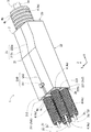
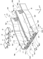
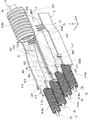
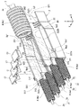
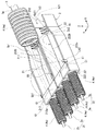
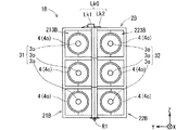
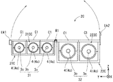
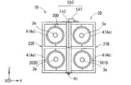
図1は、一実施形態に係るワイヤーハーネス1を例示する概略斜視図である。図2は、一実施形態に係るプロテクタ2を概略的に例示する分解斜視図である。図3は、プロテクタ2内に電線群3を配索する様子を例示する概略斜視図である。図4は、第1及び第2電線導出部213,223に蓋部C1を取り付ける様子を例示する概略斜視図である。図5は、第1及び第2電線導出部213,223に蓋部C1が取り付けられた様子を例示する概略斜視図である。図1から図5及び後述する図6から図15には、プロテクタ2の長手方向を+X方向とし、プロテクタ2の幅方向を+Y方向とする、右手系のXYZ座標系が付されている。
<1-1. Outline of wire harness>
FIG. 1 is a schematic perspective view illustrating a wire harness 1 according to an embodiment. FIG. 2 is an exploded perspective view schematically illustrating the
一実施形態に係るワイヤーハーネス1は、例えば、プロテクタ2と、電線群3と、コルゲートチューブ4とを備えている。ワイヤーハーネス1は、例えば、電源供給或いは信号通信に用いられる複数の電線が束にされた集合部品である。なお、プロテクタ2が取り付けられたワイヤーハーネス1は、例えば、プロテクタ付ワイヤーハーネスとも称される。
The wire harness 1 which concerns on one Embodiment is provided with the
<1−2.電線群>
電線群3は、例えば、複数の電線が束ねられたものであり、プロテクタ2に導入される1本以上の電線(被導入線とも言う)3eと、プロテクタ2から導出される1本以上の電線(被導出線とも言う)3oと、を含んでいる。本実施形態では、1本の被導入線3eがプロテクタ2に導入され、1本の被導入線3eが枝分かれした4本の被導出線3oがプロテクタから導出されている。つまり、ここでは、1本の被導入線3eは、複数本の電線によって構成されている。このとき、被導入線3eは、複数本の電線が束ねられることで形成され得る。その結果、被導入線3eは、複数本の電線が束ねられたもの(電線束とも言う)となり得る。また、被導出線3oは、例えば、1本の電線で構成されてもよいし、2本以上の電線が束ねられた電線束で構成されてもよい。電線群3は、例えば、車両等に配索されて、各種電気部品同士を電気的に接続する配線材として用いられる。電線群3には、光ファイバーケーブル等が含まれていてもよい。図1及び図3から図15には、被導入線3e及び被導出線3oの概形が描かれている。また、図3から図5には、プロテクタ2内に電線(ここでは、被導出線3o)が配される経路(配設経路とも言う)の外縁が二点鎖線で描かれている。
<1-2. Wire group>
The electric wire group 3 is, for example, a bundle of a plurality of electric wires. One or more electric wires (also referred to as introduced wires) 3e introduced into the
<1−3.コルゲートチューブ>
コルゲートチューブ4は、長手方向に山部4pと谷部4rとが連続して形成された外周部を有している。コルゲートチューブ4は、筒状に形成されている。具体的には、コルゲートチューブ4では、山部4pは、谷部4rよりも径方向に突出する環状の凸部であり、谷部4rは、山部4pよりも径方向に凹んでいる環状の凹部である。山部4pと谷部4rとは、コルゲートチューブ4の長手方向に沿って交互に形成されている。すなわち、コルゲートチューブ4は、環状の凸部と環状の凹部とが交互に配された外形を有している管状の部材である。ここでは、コルゲートチューブ4の長手方向に直交する方向に沿って切断した断面は、例えば、円形状であっても、楕円形状等のその他の形状であってもよい。
<1-3. Corrugated tube>
The
コルゲートチューブ4の素材としては、例えば、樹脂等のある程度の柔軟性を有し且つ弾性変形が可能な素材が採用され得る。該樹脂には、例えば、ゴム等が含まれる。この場合、例えば、コルゲートチューブ4は、環状の凸部と環状の凹部との間の段部等で比較的容易に弾性変形するため、全体として曲げ変形が容易な性質を有している。
As a material of the
コルゲートチューブ4は、例えば、電線群3のうち、被導入線3e及び各被導出線3oの周囲をそれぞれ覆うことで、被導入線3e及び各被導出線3oを保護することができる。ここで、コルゲートチューブ4には、例えば、被導入線3eの周囲を覆うコルゲートチューブ(入側コルゲートチューブとも言う)4e、及び各被導出線3oの周囲を覆うコルゲートチューブ(出側コルゲートチューブとも言う)4oが含まれる。
For example, the
ここで、例えば、コルゲートチューブ4に、長手方向に沿ったスリットが形成されていれば、該スリットが割り開かれて、該コルゲートチューブ4の内部の空間に電線が収容され得る。また、例えば、コルゲートチューブ4にスリットが形成されていなければ、該コルゲートチューブ4の一方側の開口から他方側の開口に向けて電線が中通しされてもよい。これらの何れの構成が採用されても、コルゲートチューブ4が電線に外装され得る。
Here, for example, if a slit along the longitudinal direction is formed in the
<1−4.プロテクタの構成>
プロテクタ2は、例えば、複数の電線を含む電線群3の外周部を保護することが可能な部材である。また、プロテクタ2は、例えば、電線群3を構成する被導入線3e及び被導出線3oの配設経路を規制することが可能である。ここで、プロテクタ2の素材として、例えば、樹脂等の適度な剛性を有する素材が採用され、プロテクタ2の厚さ及び形状が調整されれば、プロテクタ2による電線群3の保護及び配設経路の規制が実現され得る。プロテクタ2の素材としての樹脂には、例えば、プラスチックス等が含まれる。プロテクタ2は、例えば、左右又は上下から接離可能な一対の金型を用いた樹脂の一体成型等によって製造され得る。なお、プロテクタ2は、例えば、3Dプリンタ等によっても成型され得る。
<1-4. Structure of protector>
For example, the
プロテクタ2は、例えば、第1プロテクタ本体部21と、第2プロテクタ本体部22と、蓋部C1と、連結部R1と、固定部Lk0と、を備えている。
The
第1プロテクタ本体部21は、例えば、半円筒状の形状を有する。ここでは、第1プロテクタ本体部21は、電線群3を側方から保護する部分(第1電線保護部とも言う)211としての役割を果たす板状の底部と、該底部の幅方向(ここでは、+Y方向)の両端部に立設されるように形成された一対の側壁部212u,212bとを有している。これにより、例えば、長手方向(ここでは、+X方向)に垂直な断面の形状がU字状である第1プロテクタ本体部21の概形が形成され得る。そして、第1プロテクタ本体部21に囲まれた空間Sp1が形成される。該空間Sp1は、電線の配設経路となり得る。
The 1st protector main-
また、第1プロテクタ本体部21は、電線の配設経路に沿った一端側(ここでは、+X側)において、第1電線保護部211上に被導入線3eを導入するための部分(第1電線導入部とも言う)201を有している。また、第1プロテクタ本体部21は、電線の配設経路に沿った他端側(ここでは、−X側)において、第1電線保護部211上に被導出線3oを導出するための部分(第1電線導出部とも言う)213を有している。
Further, the first protector
第1電線導入部201には、例えば、空間Sp1の延在方向に垂直な方向に延在している1本以上(ここでは、3本)の突起部L0が、空間Sp1側に突起するように第1電線保護部211上に立設されている。突起部L0は、入側コルゲートチューブ4eの外周の谷部4rに嵌合することが可能な形状を有している。これにより、第1電線導入部201では、空間Sp1の一端側の開口Op11から第1プロテクタ本体部21内に延びる入側コルゲートチューブ4eが嵌合可能な半筒状の溝部G11が形成されている。
In the first electric
第1電線導出部213は、第1電線保護部211上において、2本以上の電線(ここでは、被導出線3o)を一列に並べた状態で保持することが可能であるとともに、該2本以上の被導出線3oをプロテクタ2の外部に導出することが可能である。本実施形態では、第1電線導出部213によって、+Y方向に一列に並べられた2本の被導出線3oがプロテクタ2の外部に導出され得る。つまり、ここでは、第1電線導出部213から導出される2本以上の被導出線3oが1つの電線群(第1電線群とも言う)31を構成する。なお、本実施形態では、被導入線3eを構成する複数本の電線の一部が枝分かれして、2本以上の被導出線3oによって第1電線群31が構成されている。このため、被導入線3eは、第1電線群31を含む。
The first wire lead-out
本実施形態では、第1電線導出部213に、仕切り板Wa1が設けられている。該仕切り板Wa1は、第1電線保護部材211上に立設され、空間Sp1の延在方向に沿って延在されている。このため、空間Sp1の他端側(ここでは、−X側)の部分が、2つ以上(ここでは、2つ)の空間に仕切られている。そして、これにより、第1電線導出部213には、開口Op12を有する溝部G12と、開口Op13を有する溝部G13とが形成されている。
In the present embodiment, the first
溝部G12には、該溝部G12によって囲まれる空間の延在方向に垂直な方向に延在している1本以上(ここでは、3本)の突起部L1が、空間Sp1側に突起するように第1電線保護部211上に立設されている。突起部L1は、出側コルゲートチューブ4oの外周の谷部4rに嵌合することが可能な形状を有している。このため、溝部G12では、第1プロテクタ本体部21内から開口Op12を介して第1プロテクタ本体部21の外部に延びる出側コルゲートチューブ4oが嵌合可能である。また、溝部G12に嵌合された出側コルゲートチューブ4oの上に、下面に出側コルゲートチューブ4oの外周の谷部4rに嵌合可能な凹凸構造を有する蓋部C1が被せられることで、溝部G12によって1本の出側コルゲートチューブ4oが安定して保持され得る。
In the groove part G12, one or more (here, three) protrusions L1 extending in a direction perpendicular to the extending direction of the space surrounded by the groove part G12 protrude so as to protrude toward the space Sp1. The first electric
溝部G13には、溝部G12と同様に、該溝部G13によって囲まれる空間の延在方向に垂直な方向に延在している1本以上(ここでは、3本)の突起部L1が、空間Sp1側に突起するように第1電線保護部211上に立設されている。突起部L1は、出側コルゲートチューブ4oの外周の谷部4rに嵌合することが可能な形状を有している。このため、溝部G13では、第1プロテクタ本体部21内から開口Op13を介して第1プロテクタ本体部21の外部に延びる出側コルゲートチューブ4oが嵌合可能である。また、溝部G13に嵌合された出側コルゲートチューブ4oの上に、下面に出側コルゲートチューブ4oの外周の谷部4rに嵌合可能な凹凸構造を有する蓋部C1が被せられることで、溝部G13によって1本の出側コルゲートチューブ4oが安定して保持され得る。
In the groove part G13, like the groove part G12, one or more (here, three) protrusions L1 extending in the direction perpendicular to the extending direction of the space surrounded by the groove part G13 are provided in the space Sp1. It stands on the 1st electric
第2プロテクタ本体部22は、例えば、XZ平面を基準として、上述した第1プロテクタ本体部21と面対称の構造を有している。
The 2nd protector main-
第2プロテクタ本体部22は、例えば、半円筒状の形状を有する。ここでは、第2プロテクタ本体部22は、電線群3を側方から保護する部分(第2電線保護部とも言う)221としての役割を果たす板状の底部と、該底部の幅方向(ここでは、+Y方向)の両端部に立設されるように形成された一対の側壁部222u,222bとを有している。これにより、例えば、長手方向(ここでは、+X方向)に垂直な断面の形状がU字状である第2プロテクタ本体部22の概形が形成され得る。そして、第2プロテクタ本体部22に囲まれた空間Sp2が形成される。該空間Sp2は、電線の配設経路となり得る。
The 2nd protector main-
また、第2プロテクタ本体部22は、電線の配設経路に沿った一端側(ここでは、+X側)において、第2電線保護部221上に被導入線3eを導入するための部分(第2電線導入部とも言う)202を有している。また、第2プロテクタ本体部22は、電線の配設経路に沿った他端側(ここでは、−X側)において、第2電線保護部221上に被導出線3oを導出するための部分(第2電線導出部とも言う)223を有している。
Further, the second protector
第2電線導入部202には、例えば、空間Sp2の延在方向に垂直な方向に延在している1本以上(ここでは、3本)の突起部L0が、空間Sp2側に突起するように第2電線保護部221上に立設されている。突起部L0は、入側コルゲートチューブ4eの外周の谷部4rに嵌合することが可能な形状を有している。これにより、第2電線導入部202では、空間Sp2の一端側の開口Op21から第2プロテクタ本体部22内に延びる入側コルゲートチューブ4eが嵌合可能な半筒状の溝部G21が形成されている。
In the second electric
第2電線導出部223は、第2電線保護部221上において、2本以上の電線(ここでは、被導出線3o)を一列に並べた状態で保持することが可能であるとともに、該2本以上の被導出線3oをプロテクタ2の外部に導出することが可能である。本実施形態では、第2電線導出部223によって、+Y方向に一列に並べられた2本の被導出線3oがプロテクタ2の外部に導出され得る。つまり、ここでは、第2電線導出部223から導出される2本以上の被導出線3oが1つの電線群(第2電線群とも言う)32を構成する。なお、本実施形態では、被導入線3eを構成する複数本の電線の一部が枝分かれして、2本以上の被導出線3oによって第2電線群31が構成されている。このため、被導入線3eは、第2電線群31を含む。
The second electric wire lead-out
本実施形態では、第2電線導出部223に、仕切り板Wa2が設けられている。該仕切り板Wa2は、第2電線保護部221上に立設され、空間Sp2の延在方向に沿って延在されている。このため、空間Sp2の他端側(ここでは、−X側)の部分が、2つ以上(ここでは、2つ)の空間に仕切られている。これにより、第2電線導出部223には、開口Op22を有する溝部G22と、開口Op23を有する溝部G23とが形成されている。
In the present embodiment, the second electric
溝部G22には、該溝部G22に囲まれている空間の延在方向に垂直な方向に延在している1本以上(ここでは、3本)の突起部L1が、空間Sp1側に突起するように第2電線保護部221上に立設されている。突起部L1は、出側コルゲートチューブ4oの外周の谷部4rに嵌合することが可能な形状を有している。このため、溝部G22では、第2プロテクタ本体部22内から開口Op22を介して第2プロテクタ本体部22の外部に延びる出側コルゲートチューブ4oが嵌合可能である。また、溝部G22に嵌合された出側コルゲートチューブ4oの上に、下面に出側コルゲートチューブ4oの外周の谷部4rに嵌合可能な凹凸構造を有する蓋部C1が被せられることで、溝部G22によって1本の出側コルゲートチューブ4oが安定して保持され得る。
In the groove G22, one or more (three in this case) protrusions L1 extending in the direction perpendicular to the extending direction of the space surrounded by the groove G22 protrude toward the space Sp1. As described above, the second electric
溝部G23には、溝部G22と同様に、該溝部G23に囲まれている空間の延在方向に垂直な方向に延在している1本以上(ここでは、3本)の突起部L1が、空間Sp2側に突起するように第2電線保護部221上に立設されている。突起部L1は、出側コルゲートチューブ4oの外周の谷部4rに嵌合することが可能な形状を有している。このため、溝部G23では、第2プロテクタ本体部22内から開口Op23を介して第2プロテクタ本体部22の外部に延びる出側コルゲートチューブ4oが嵌合可能である。また、溝部G23に嵌合された出側コルゲートチューブ4oの上に、下面に出側コルゲートチューブ4oの外周の谷部4rに嵌合可能な凹凸構造を有する蓋部C1が被せられることで、溝部G23によって1本の出側コルゲートチューブ4oが安定して保持され得る。
In the groove part G23, similarly to the groove part G22, one or more (here, three) protrusions L1 extending in a direction perpendicular to the extending direction of the space surrounded by the groove part G23, It stands on the 2nd electric
連結部R1は、第1プロテクタ本体部21と第2プロテクタ本体部22とを回動可能に連結している。連結部R1は、例えば、空間Sp1が上方(ここでは、+Z方向)を向くように配置された第1プロテクタ本体部21の側壁部212bと、空間Sp2が上方(ここでは、+Z方向)を向くように配置された第2プロテクタ本体部22の側壁部222bとが、略平行に配置された状態で、側壁部212bの上端部と側壁部222bの上端部とを回動可能に連結する。ここでは、2つの連結部R1が設けられているが、少なくとも1つの連結部R1が設けられていればよい。連結部R1としては、例えば、蝶番の構造又は弾性変形が可能な薄肉部等のヒンジ部が採用され得る。
The connecting portion R1 connects the first protector
このような連結部R1により、第1プロテクタ本体部21と第2プロテクタ本体部22とを相対的に回動させることができる。これにより、プロテクタ2を、図5で示されているような空間Sp1と空間Sp2とが外部の空間に開放されている第1状態(開状態とも言う)から、図1で示されているような空間Sp1と空間Sp2とが向かい合わせに配置されて、外部の空間に対して閉じられている第2状態(閉状態とも言う)に、遷移させることが可能である。
By such a connection part R1, the 1st protector main-
このように、連結部R1によって、一対のプロテクタ本体部21,22が回動可能に連結されていれば、一対のプロテクタ本体部21,22が容易に向かい合わせに固定され得る。すなわち、一対の電線保護部211,221で第1及び第2電線群31,32が挟まれたプロテクタ2を含むワイヤーハーネス1の構造が容易に完成され得る。
Thus, if the pair of protector
ここで、開状態では、第1電線保護部211と第2電線保護部221とが、第1電線導出部213及び第2電線導出部223を挟んで対向していない。
Here, in the open state, the first electric
これに対して、閉状態では、第1電線保護部211と第2電線保護部221とが第1電線導出部213及び第2電線導出部223を挟んで対向している。つまり、第1電線保護部211と第2電線保護部221との間に、第1電線導出部213と第2電線導出部223とが、この順に挟まれている。このとき、半筒状の溝部G11と半筒状の溝部G21とが向かい合うことで、入側コルゲートチューブ4eが固定され得る円筒状の電線導入部20が形成される。また、第1プロテクタ本体部21と第2プロテクタ本体部22とが1つの円筒状のプロテクタ2を形成する。具体的には、例えば、第1プロテクタ本体部21の側壁部212bと、第2プロテクタ本体部22の側壁部222bとが、プロテクタ2の1つの底面部2bを構成する。また、例えば、第1プロテクタ本体部21の側壁部212uと、第2プロテクタ本体部22の側壁部222uとが、プロテクタ2の1つの上面部2uを構成する。また、第1プロテクタ本体部21の底部が、プロテクタ2の一方の側面部2s1を構成し、第2プロテクタ本体部22の底部が、プロテクタ2の他方の側面部2s2を構成する。このため、空間Sp1と空間Sp2とが1つの筒を貫通する中空の空間を形成する。
On the other hand, in the closed state, the first electric
換言すれば、閉状態のプロテクタ2は、電線導入部20を備えており、電線導入部20から第1電線導出部213にかけて電線の配設が可能であり且つ保護することができ、電線導入部20から第2電線導出部223にかけて電線の配設が可能であり且つ保護することができる。
In other words, the
固定部Lk0は、第1電線保護部211と第2電線保護部221とが、第1電線導出部213及び第2電線導出部223を挟んでいる状態で、第1プロテクタ本体部21と第2プロテクタ本体部22とを相互に固定することができる。このため、連結部R1によって閉状態とされると、第1プロテクタ本体部21と第2プロテクタ本体部22とが固定部Lk0によって相互に固定され得る。
The fixing portion Lk0 is configured so that the
固定部Lk0は、例えば、嵌合、螺合及び係止等の何れの態様によって、第1プロテクタ本体部21と第2プロテクタ本体部22とを相互に固定してもよい。本実施形態では、固定部Lk0として、被嵌合部Lk1の貫通孔に、嵌合部Lk2の先端部に設けられたロック片が挿通されることで、嵌合部Lk2が被嵌合部Lk1に嵌合され得る構造が採用されている。なお、ここでは、被嵌合部Lk1が、第1プロテクタ本体部21の側壁部212uの上端部近傍に設けられ、嵌合部Lk2が、第2プロテクタ本体部22の側壁部222uの上端部近傍に設けられている。
The fixing portion Lk0 may fix the first protector
<1−5.ワイヤーハーネスの製造>
ここで、本実施形態に係るワイヤーハーネス1の製造の手順について説明する。
<1-5. Manufacture of wire harness>
Here, the manufacturing procedure of the wire harness 1 according to this embodiment will be described.
まず、例えば、図2で示されるようにプロテクタ2が閉状態とされる。
First, for example, the
次に、図3で示されるように、入側コルゲートチューブ4eによって外周が覆われた被導入線3eから引き出された4本の被導出線3oが、1本ずつ第1電線導出部213及び第2電線導出部223に保持させられる。このとき、例えば、入側コルゲートチューブ4eが、第1電線導入部201と第2電線導入部202の間の部分の上方に配置される。具体的には、例えば、入側コルゲートチューブ4eが、第1プロテクタ本体部21の側壁部212bと第2プロテクタ本体部22の側壁部222bとの上に載置される。このとき、例えば、プロテクタ2に部材が設けられるか、治具が使用されることで、入側コルゲートチューブ4eが安定して保持されるようにしてもよい。
Next, as shown in FIG. 3, the four lead wires 3o led out from the
そして、1本目の被導出線3oが、空間Sp1を通り且つ開口Op12から第1プロテクタ本体部21の外部に導出されるように配置され、1本目の被導出線3oの外周部を覆う出側コルゲートチューブ4oが、第1電線導出部213の溝部G12に嵌合される。また、2本目の被導出線3oが、空間Sp1を通り且つ開口Op13から第1プロテクタ本体部21の外部に導出されるように配置され、2本目の被導出線3oの外周部を覆う出側コルゲートチューブ4oが、第1電線導出部213の溝部G13に嵌合される。また、3本目の被導出線3oが、空間Sp2を通り且つ開口Op22から第2プロテクタ本体部22の外部に導出されるように配置され、3本目の被導出線3oの外周部を覆う出側コルゲートチューブ4oが、第2電線導出部223の溝部G22に嵌合される。また、4本目の被導出線3oが、空間Sp2を通り且つ開口Op23から第2プロテクタ本体部22の外部に導出されるように配置され、4本目の被導出線3oの外周部を覆う出側コルゲートチューブ4oが、第2電線導出部223の溝部G23に嵌合される。
The first lead-out line 3o is arranged so as to be led out through the space Sp1 and from the opening Op12 to the outside of the first protector
次に、図4及び図5で示されるように、溝部G12,G13,G22,G23にそれぞれ嵌合された出側コルゲートチューブ4oの上に、蓋部C1がそれぞれ被せられる。このとき、各出側コルゲートチューブ4oの外周の谷部4rに、蓋部C1の下面の設けられた凸部が嵌合することで、4本の出側コルゲートチューブ4oが、第1電線導出部213及び第2電線導出部223に安定して保持される。
Next, as shown in FIGS. 4 and 5, the lid portions C <b> 1 are respectively placed on the outlet side corrugated tubes 4 o fitted in the groove portions G <b> 12, G <b> 13, G <b> 22, G <b> 23. At this time, the convex part provided in the lower surface of the cover part C1 fits into the
そして、図5及び図1で示されるように、連結部R1によって、第1プロテクタ本体部21と第2プロテクタ本体部22が相対的に回動されることで、プロテクタ2が閉状態とされる。このとき、入側コルゲートチューブ4eが、溝部G11と溝部G21によって挟み込まれる。そして、入側コルゲートチューブ4eの外周の谷部4rに、両溝部G11,G21の突起部L0が嵌合されることで、電線導入部20に入側コルゲートチューブ4eが固定された状態となる。また、このとき、固定部Lk0によって、第1電線保護部211と第2電線保護部221とが第1電線導出部213及び第2電線導出部223を挟んでいる状態で、第1プロテクタ本体部21と第2プロテクタ本体部22とが相対的に固定され得る。これにより、第1プロテクタ本体部21と第2プロテクタ本体部22とが相互に固定されたワイヤーハーネス1が完成され得る。
As shown in FIGS. 5 and 1, the
このとき、ワイヤーハーネス1には、第1電線導出部213において一列にならべられた状態で保持され且つプロテクタ2から導出されている2本以上(ここでは、2本)の被導出線3oを含む第1電線群31、並びに第2電線導出部223において一列にならべられた状態で保持され且つプロテクタ2から導出されている2本以上(ここでは、2本)の被導出線3oを含む第2電線群32が含まれている。そして、被導出線3oがそれぞれ保持されている溝部G12,G13,G22,G23が、溝部G12と溝部G22が一段目に並び、溝部G13と溝部G23とが二段目に並んでいる状態となる。つまり、複数の被導出線3oが、2列以上に並べられた状態で、プロテクタ2から導出されている。
At this time, the wire harness 1 includes two or more lead wires 3o that are held in a row in the first electric wire lead-out
このようなワイヤーハーネス1の製造の手順によれば、被導入線3eが、例えば、複数の被導出線3oに分岐され、一対のプロテクタ本体部21,22に組み付けられた後に、一対のプロテクタ本体部21,22が向かい合わせに固定される。このため、例えば、プロテクタ2内に複数の被導出線3oが収容される際における複数の被導出線3oの移動距離が短くなり得る。これにより、例えば、複数の被導出線3oにおける、移動を可能とするための余裕を与えるための長さ(余長とも言う)が短縮され得る。その結果、余長の短縮による材料の使用量の低減が図られるとともに、複数の被導出線3oが各部に干渉し難く、ワイヤーハーネス1の製造が容易となり得る。
According to the procedure of manufacturing such a wire harness 1, the introduced
<1−6.一実施形態のまとめ>
以上のように、本実施形態に係るプロテクタ2によれば、例えば、一対の電線導出部213,223に2以上の被導出線3oがそれぞれ一列にならべられた一対のプロテクタ本体部21,22が向かい合わせに固定されることで、2つの電線群3が一対の電線保護部211,221で挟まれたプロテクタ2の構造が完成され得る。このため、例えば、複数の電線を平面的に配索した後に、2段以上で配置された電線が容易に実現され得る。これにより、例えば、一対のプロテクタ本体部21,22の小型化及びプロテクタ2の構造の簡素化等が図られ得る。したがって、限られた空間において複数の電線の導出が可能であり且つ容易に製造可能なプロテクタ2及びワイヤーハーネス1が実現され得る。
<1-6. Summary of Embodiment>
As described above, according to the
<2.変形例>
なお、本発明は上述の一実施形態に限定されるものではなく、本発明の要旨を逸脱しない範囲において種々の変更、改良等が可能である。
<2. Modification>
Note that the present invention is not limited to the above-described embodiment, and various modifications and improvements can be made without departing from the gist of the present invention.
例えば、上記一実施形態では、第1プロテクタ本体部21と第2プロテクタ本体部22とが回動可能に連結されていたが、これに限られない。例えば、第1プロテクタ本体部21と第2プロテクタ本体部22とが、相互に離間しており且つ連結されていない第1状態(図6)、及び固定部Lk0によって相互に固定されている第2状態(図7)の何れか一方の状態に、選択的に設定され得る、プロテクタ2Aが採用されてもよい。このような構成が採用されれば、例えば、一対のプロテクタ本体部21,22が相互に連結されていない別体のプロテクタ本体部21,22によって構成されるため、プロテクタ2が容易に製造され得る。
For example, in the above-described embodiment, the first protector
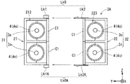
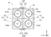
図6は、第1変形例に係るプロテクタ2Aの開状態、すなわちワイヤーハーネス1Aの作成態様を示す概略正面図である。図7は、第1変形例に係るプロテクタ2Aの閉状態、すなわちワイヤーハーネス1Aを示す概略正面図である。ここでは、例えば、プロテクタ2Aの上面部側の固定部Lk0に加えて、プロテクタ2Aの下面部側に、被嵌合部Lk1Aと嵌合部Lk2Aとを有する他の固定部Lk0Aが設けられている。これにより、第1プロテクタ本体部21と第2プロテクタ本体部22とが相互に離間している開状態から、第1プロテクタ本体部21と第2プロテクタ本体部22とが相互に向かい合って固定されている閉状態に遷移させることが可能である。
FIG. 6 is a schematic front view showing an open state of the
また、上記一実施形態及び上記第1変形例では、第1電線導出部213及び第2電線導出部223が、それぞれ2本の被導出線3o及び該2本の被導出線3oの外周部をそれぞれ囲む3本の出側コルゲートチューブ4oを保持及び導出することが可能な2つの溝部を有していたが、これに限られない。例えば、第1電線導出部213及び第2電線導出部223が、それぞれ2本以上の任意の本数の被導出線3o及び出側コルゲートチューブ4oを保持及び導出することが可能であってもよい。第1電線導出部213と第2電線導出部223との間で、保持及び導出が可能な被導出線3o及び出側コルゲートチューブ4oの本数は、同一であっても、異なっていてもよい。
In the one embodiment and the first modified example, the first wire lead-out
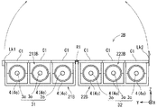
図8は、第2変形例に係るプロテクタ2Bの開状態、すなわちワイヤーハーネス1Bの作成態様を示す概略正面図である。図9は、第2変形例に係るプロテクタ2Bの閉状態、すなわちワイヤーハーネス1Bを示す概略正面図である。図8及び図9で示されるように、第2変形例に係るプロテクタ2Bは、上記一実施形態に係るプロテクタ2をベースとして、第1プロテクタ本体部21が、第1プロテクタ本体部21Bに変更され、第2プロテクタ本体部22が、第2プロテクタ本体部22Bに変更されたものである。第1プロテクタ本体部21Bは、3本の被導出線3o及び該3本の被導出線3oの外周部をそれぞれ囲む3本の出側コルゲートチューブ4oを保持及び導出することが可能な3つの溝部を有する第1電線導出部213Bを備えている。第2プロテクタ本体部22Bは、3本の被導出線3o及び該3本の被導出線3oの外周部をそれぞれ囲む3本の出側コルゲートチューブ4oを保持及び導出することが可能な3つの溝部を有する第2電線導出部223Bを備えている。
FIG. 8 is a schematic front view showing an open state of the
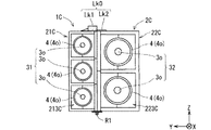
図10は、第3変形例に係るプロテクタ2Cの開状態、すなわちワイヤーハーネス1Cの作成態様を示す概略正面図である。図11は、第3変形例に係るプロテクタ2Cの閉状態、すなわちワイヤーハーネス1Cを示す概略正面図である。図10及び図11で示されるように、第3変形例に係るプロテクタ2Cは、上記一実施形態に係るプロテクタ2をベースとして、第1プロテクタ本体部21が、第1プロテクタ本体部21Cに変更され、第2プロテクタ本体部22が、第2プロテクタ本体部22Cに変更されたものである。第1プロテクタ本体部21Cは、3本の被導出線3o及び該3本の被導出線3oの外周部をそれぞれ囲む3本の出側コルゲートチューブ4oを保持及び導出することが可能な3つの溝部を有する第1電線導出部213Cを備えている。第2プロテクタ本体部22Cは、2本の被導出線3o及び該2本の被導出線3oの外周部をそれぞれ囲む2本の出側コルゲートチューブ4oを保持及び導出することが可能な2つの溝部を有する第2電線導出部223Cを備えている。
FIG. 10 is a schematic front view showing an open state of the protector 2C according to the third modification, that is, a manner of creating the wire harness 1C. FIG. 11: is a schematic front view which shows the closed state of the protector 2C which concerns on a 3rd modification, ie, the wire harness 1C. As shown in FIGS. 10 and 11, the protector 2C according to the third modification is based on the
また、上記一実施形態及び上記第1〜3変形例では、1本の被導入線3e及び該1本の被導入線3eの外周部を囲む1本の入側コルゲートチューブ4eを導入及び保持することが可能な電線導入部20が採用されたが、これに限られない。例えば、電線導入部20において、複数本の被導入線3eが導入されてもよい。つまり、例えば、電線導入部20において、2本以上の任意の本数の被導入線3e及び入側コルゲートチューブ4eを保持及び導入することが可能であってもよい。このとき、電線導入部20において導入される被導入線3eがプロテクタの内部で枝分かれすることなく、そのまま被導出線3oとされてもよい。つまり、電線導入部20で導入される被導入線3eの本数と、第1及び第2電線導出部213,223で導出される被導出線3oの本数とは、同一であってもよいし、異なっていてもよい。
Moreover, in the said one Embodiment and the said 1st-3rd modification, the one inlet side corrugated
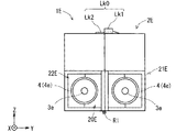
図12は、第4変形例に係るプロテクタ2Dの開状態、すなわちワイヤーハーネス1Dの作成態様を示す概略背面図である。図13は、第4変形例に係るプロテクタ2Dの閉状態、すなわち第4変形例に係るワイヤーハーネス1Dを示す概略背面図である。第4変形例に係るプロテクタ2Dは、上記一実施形態に係るプロテクタ2をベースとして、第1プロテクタ本体部21が、第1プロテクタ本体部21Dに変更され、第2プロテクタ本体部22が、第2プロテクタ本体部22Dに変更されたものである。第1プロテクタ本体部21Dは、2本の被導入線3e及び2本の入側コルゲートチューブ4eの保持及び導入が単独で可能な第1電線導入部201Dを有し、第2プロテクタ本体部22Dは、2本の被導入線3e及び2本の入側コルゲートチューブ4eの保持及び導入が単独で可能な第2電線導入部202Dを有している。このとき、第1電線導入部201Dと第2電線導入部202Dとが、プロテクタ2Dにおいて2本以上の被導入線2eを導入する電線導入部20Dを構成している。この場合、例えば、合計4本の被導入線3eが、第1電線導出部213及び第2電線導出部223からそのまま4本の被導出線3oとして導出されてもよい。なお、第1電線導入部201D及び第2電線導入部202Dにおける各入側コルゲートチューブ4eの保持は、例えば、第1及び第2電線導出部213,223と同様な構成によって実現され得る。
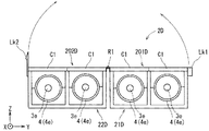
FIG. 12 is a schematic rear view showing an open state of the protector 2D according to the fourth modified example, that is, how the wire harness 1D is created. FIG. 13 is a schematic rear view showing the closed state of the protector 2D according to the fourth modification, that is, the wire harness 1D according to the fourth modification. The protector 2D according to the fourth modification is based on the
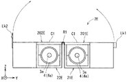
図14は、第5変形例に係るプロテクタ2Eの開状態、すなわちワイヤーハーネス1Eの作成態様を示す概略背面図である。図15は、第5変形例に係るプロテクタ2Eの閉状態、すなわち第5変形例に係るワイヤーハーネス1Eを示す概略背面図である。第5変形例に係るプロテクタ2Eは、上記一実施形態に係るプロテクタ2をベースとして、第1プロテクタ本体部21が、第1プロテクタ本体部21Eに変更され、第2プロテクタ本体部22が、第2プロテクタ本体部22Eに変更されたものである。第1プロテクタ本体部21Eは、1本の被導入線3e及び1本の入側コルゲートチューブ4eを保持及び導入することが単独で可能な第1電線導入部201Eを有し、第2プロテクタ本体部22Eは、1本の被導入線3e及び1本の入側コルゲートチューブ4eを保持及び導入することが単独で可能な第2電線導入部202Eを有している。このとき、第1電線導入部201Eと第2電線導入部202Eとが、プロテクタ2Eにおいて2本以上の被導入線2eを導入する電線導入部20Eを構成している。この場合、例えば、第1電線導入部201Eで導入された1本の被導入線3eが2本の被導出線3oに枝分かれして、該2本の被導出線3oが第1電線導出部213から導出され、第2電線導入部202Eで導入された1本の被導入線3eが2本の被導出線3oに枝分かれして、該2本の被導出線3oが第2電線導出部223から導出される態様が採用されてもよい。
FIG. 14 is a schematic rear view showing an open state of the
また、上記一実施形態及び上記第1〜5変形例では、被導入線3e及び被導出線3oの外周が、それぞれコルゲートチューブ4によって囲まれたが、これに限られない。例えば、被導入線3e及び被導出線3oの外周が、コルゲートチューブ以外の管状の部材等によって囲まれていてもよい。
Moreover, in the said one Embodiment and the said 1st-5th modification, the outer periphery of the to-
また、上記一実施形態及び上記第1〜5変形例では、例えば、第1及び第2電線導出部213,213B,213C,223,223B,223Cにおいて、蓋部C1の代わりに、粘着力を有するテープ或いはタイバンド等のその他の部材を用いて各被導出線3oが固定されてもよい。
Moreover, in the said one Embodiment and the said 1st-5th modification, in 1st and 2nd electric wire derivation | leading-out
また、上記一実施形態及び上記第1〜5変形例では、例えば、プロテクタ2,2A〜2Eにおいて被導出線3oが導出される位置が、ワイヤーハーネス1,1A〜1Eが搭載される対象物の設計に合わせて、適宜変更及び調整されてもよい。
Moreover, in the said one Embodiment and the said 1st-5th modification, the position where the to-be-derived line 3o is derived | led-out in the
また、上記一実施形態及び上記第1〜5変形例では、例えば、電線導入部20,20D,20E、第1電線導入部201,201D,201E及び第2電線導入部202,202D,202Eの代わりに、電線が接続されるコネクタが設けられてもよい。この場合、プロテクタ2,2A〜2Eには、電線が外部から導入されずに接続される。
Moreover, in the said one Embodiment and the said 1st-5th modification, instead of the electric
また、上記一実施形態及び上記第1〜5変形例では、例えば、連結部R1の代わりに、第1プロテクタ本体部21,21A〜22Eと第2プロテクタ本体部22,22A〜22Eとを回動可能に係合する構造が採用されてもよい。
In the embodiment and the first to fifth modifications, for example, the first protector
また、上記一実施形態及び上記第1〜5変形例では、例えば、固定部Lk0,Lk0Aの代わりに、粘着性を有するテープ或いはタイバンド等の帯状或いは線状の部材によって、第1プロテクタ本体部21,21A〜22Eと第2プロテクタ本体部22,22A〜22Eとが相互に固定されてもよい。
In the one embodiment and the first to fifth modifications, for example, instead of the fixing portions Lk0 and Lk0A, the first protector main body portion is formed by a band-like or linear member such as an adhesive tape or a tie band. 21 and 21A-22E and the 2nd protector main-
また、上記一実施形態及び上記第1〜5変形例では、例えば、第1プロテクタ本体部21,21A〜22Eと第2プロテクタ本体部22,22A〜22Eが、板状の部材で構成されずに、網状或いは格子状等、外部の部材との干渉から電線を保護することが可能である種々の部材によって構成されてもよい。また、例えば、第1プロテクタ本体部21,21A〜22Eと第2プロテクタ本体部22,22A〜22Eの一部に、他の部材との干渉が生じない程度の開口が設けられていてもよい。
Moreover, in the said one Embodiment and the said 1st-5th modification, for example, the 1st protector main-
以上のように、この発明は詳細に説明されたが、上記した説明は、すべての局面において、例示であって、この発明がそれに限定されるものではない。例示されていない無数の変形例が、この発明の範囲から外れることなく想定され得るものと解される。 As mentioned above, although this invention was demonstrated in detail, above-described description is an illustration in all the aspects, Comprising: This invention is not limited to it. It is understood that countless variations that are not illustrated can be envisaged without departing from the scope of the present invention.
1,1A〜1E ワイヤーハーネス
2,2A〜2E プロテクタ
20,20D,20E 電線導入部
201,201D,201E 第1電線導入部
202,202D,202E 第2電線導入部
21,21A〜22E 第1プロテクタ本体部
211 第1電線保護部
212b,212u,222b,222u 側壁部
213,213B,213C 第1電線導出部
22,22A〜22E 第2プロテクタ本体部
221 第2電線保護部
223,223B,223C 第2電線導出部
2s1,2s2 側面部
3 電線群
31 第1電線群
31 第2電線群
3e 被導入線
3o 被導出線
4 コルゲートチューブ
4e 入側コルゲートチューブ
4o 出側コルゲートチューブ
C1 蓋部
G11〜G13,G21〜G23 溝部
Lk0,Lk0A 固定部
Op11〜Op13,Op21〜Op23 開口
R1 連結部
Sp1,Sp2 空間
DESCRIPTION OF
Claims (6)
第1電線保護部と、前記第1電線保護部上において第1電線群を構成する2本以上の電線を一列に並べた状態で保持し且つ外部に導出することが可能な第1電線導出部とを有する第1プロテクタ本体部と、
第2電線保護部と、前記第2電線保護部上において第2電線群を構成する2本以上の電線を一列に並べた状態で保持し且つ外部に導出することが可能な第2電線導出部とを有する第2プロテクタ本体部と、
前記第1電線保護部と前記第2電線保護部とが前記第1電線導出部及び前記第2電線導出部を挟んでいる状態で、前記第1プロテクタ本体部と前記第2プロテクタ本体部とを相互に固定することが可能な固定部と、を備えた、プロテクタ。 A protector for protecting an electric wire,
A first electric wire protection part and a first electric wire lead-out part capable of holding two or more electric wires constituting the first electric wire group in a line on the first electric wire protection part and leading out to the outside A first protector body having:
A second electric wire protecting portion and a second electric wire deriving portion capable of holding two or more electric wires constituting the second electric wire group in a row on the second electric wire protecting portion and leading out to the outside. A second protector body having
In a state where the first electric wire protection part and the second electric wire protection part sandwich the first electric wire lead-out part and the second electric wire lead-out part, the first protector main part and the second protector main part are A protector comprising: a fixing portion that can be fixed to each other.
前記第1プロテクタ本体部と前記第2プロテクタ本体部とを回動可能に連結する連結部、を更に備え、
前記連結部が、
前記第1プロテクタ本体部と前記第2プロテクタ本体部とを相対的に回動させることで、前記第1電線保護部と前記第2電線保護部とが前記第1電線導出部及び前記第2電線導出部を挟んで対向していない第1状態から、前記第1電線保護部と前記第2電線保護部とが前記第1電線導出部及び前記第2電線導出部を挟んで対向しており且つ前記第1プロテクタ本体部と前記第2プロテクタ本体部とが前記固定部によって相互に固定されている第2状態に遷移させることが可能である、プロテクタ。 The protector according to claim 1,
A connecting portion that rotatably connects the first protector main body and the second protector main body;
The connecting portion is
By rotating the first protector main body and the second protector main body relatively, the first electric wire protection portion and the second electric wire protection portion become the first electric wire lead-out portion and the second electric wire. From the first state that is not opposed across the lead-out portion, the first wire protection portion and the second wire protection portion are opposed across the first wire lead-out portion and the second wire lead-out portion, and The protector which can be changed to the 2nd state to which the said 1st protector main-body part and the said 2nd protector main-body part are mutually fixed by the said fixing | fixed part.
前記第1プロテクタ本体部と前記第2プロテクタ本体部とが、相互に離間しており且つ連結されていない第1状態、及び前記第1電線保護部と前記第2電線保護部とが前記第1電線導出部及び前記第2電線導出部を挟んで対向しており且つ前記固定部によって相互に固定されている第2状態の何れか一方の状態に、選択的に設定することが可能な、プロテクタ。 The protector according to claim 1,
The first protector body and the second protector body are separated from each other and are not connected to each other, and the first wire protector and the second wire protector are in the first state. A protector that can be selectively set to any one of the second states that are opposed to each other with the wire lead-out portion and the second wire lead-out portion interposed therebetween and are fixed to each other by the fixing portion. .
複数本の電線を導入することが可能な電線導入部、を備え、
前記電線導入部から前記第1電線導出部にかけて電線の配設が可能であり且つ電線を保護することが可能であるとともに、前記電線導入部から前記第2電線導出部にかけて電線の配設が可能であり且つ電線を保護することが可能である、プロテクタ。 The protector according to any one of claims 1 to 3, wherein
A wire introduction section capable of introducing a plurality of wires,
An electric wire can be arranged from the electric wire introducing portion to the first electric wire outlet portion and can be protected, and an electric wire can be arranged from the electric wire introducing portion to the second electric wire outlet portion. And a protector capable of protecting the electric wire.
前記第1電線導出部において一列に並べられた状態で保持され且つ前記プロテクタから導出されている2本以上の電線を含む第1電線群と、
前記第2電線導出部において一列に並べられた状態で保持され且つ前記プロテクタから導出されている2本以上の電線を含む第2電線群と、を備え、
前記固定部が、
前記第1電線保護部と前記第2電線保護部とが前記第1電線導出部及び前記第2電線導出部を挟んでいる状態で、前記第1プロテクタ本体部と前記第2プロテクタ本体部とを相互に固定している、プロテクタ付ワイヤーハーネス。 The protector according to any one of claims 1 to 4, and
A first electric wire group including two or more electric wires that are held in a row in the first electric wire outlet and are led out from the protector;
A second wire group that includes two or more wires that are held in a row in the second wire lead-out portion and are led out from the protector;
The fixing part is
In a state where the first electric wire protection part and the second electric wire protection part sandwich the first electric wire lead-out part and the second electric wire lead-out part, the first protector main part and the second protector main part are Wire harness with protector that is fixed to each other.
前記電線導入部から前記導入された複数本の電線と、を備え、
前記複数本の電線が、
前記複数本の電線の少なくとも一部が枝分かれして、前記第1電線導出部において一列に並べられた状態で保持され且つ前記プロテクタから導出されている2本以上の電線を含む第1電線群と、
前記複数本の電線の少なくとも一部が枝分かれして、前記第2電線導出部において一列に並べられた状態で保持され且つ前記プロテクタから導出されている2本以上の電線を含む第2電線群と、を含んでおり、
前記固定部が、
前記第1電線保護部と前記第2電線保護部とが前記第1電線導出部及び前記第2電線導出部を挟んでいる状態で、前記第1プロテクタ本体部と前記第2プロテクタ本体部とを相互に固定している、プロテクタ付ワイヤーハーネス。 A protector according to claim 4;
A plurality of electric wires introduced from the electric wire introduction part,
The plurality of electric wires are
A first electric wire group including two or more electric wires that are branched from at least a part of the plurality of electric wires and are held in a line in the first electric wire outlet and are led out from the protector; ,
A second electric wire group including two or more electric wires that are branched from at least a part of the plurality of electric wires and are held in a row in the second electric wire lead-out portion and are led out from the protector; Including,
The fixing part is
In a state where the first electric wire protection part and the second electric wire protection part sandwich the first electric wire lead-out part and the second electric wire lead-out part, the first protector main part and the second protector main part are Wire harness with protector that is fixed to each other.
Priority Applications (1)
| Application Number | Priority Date | Filing Date | Title |
|---|---|---|---|
| JP2016090990A JP2017200375A (en) | 2016-04-28 | 2016-04-28 | Protector and wire harness with protector |
Applications Claiming Priority (1)
| Application Number | Priority Date | Filing Date | Title |
|---|---|---|---|
| JP2016090990A JP2017200375A (en) | 2016-04-28 | 2016-04-28 | Protector and wire harness with protector |
Publications (1)
| Publication Number | Publication Date |
|---|---|
| JP2017200375A true JP2017200375A (en) | 2017-11-02 |
Family
ID=60238450
Family Applications (1)
| Application Number | Title | Priority Date | Filing Date |
|---|---|---|---|
| JP2016090990A Pending JP2017200375A (en) | 2016-04-28 | 2016-04-28 | Protector and wire harness with protector |
Country Status (1)
| Country | Link |
|---|---|
| JP (1) | JP2017200375A (en) |
Cited By (3)
| Publication number | Priority date | Publication date | Assignee | Title |
|---|---|---|---|---|
| WO2020194798A1 (en) * | 2019-03-27 | 2020-10-01 | 住友電装株式会社 | Wire harness |
| CN116495255A (en) * | 2023-05-09 | 2023-07-28 | 苏州惠斯福自动化科技有限公司 | A multi-type bundling device for air-conditioning wire harness |
| JP2024545243A (en) * | 2021-12-15 | 2024-12-05 | レオニ ボルトネッツ-ジステーメ ゲーエムベーハー | Power supply line and device equipped with such a power supply line |
-
2016
- 2016-04-28 JP JP2016090990A patent/JP2017200375A/en active Pending
Cited By (7)
| Publication number | Priority date | Publication date | Assignee | Title |
|---|---|---|---|---|
| WO2020194798A1 (en) * | 2019-03-27 | 2020-10-01 | 住友電装株式会社 | Wire harness |
| JPWO2020194798A1 (en) * | 2019-03-27 | 2020-10-01 | ||
| CN113615023A (en) * | 2019-03-27 | 2021-11-05 | 住友电装株式会社 | Wire harness |
| JP7180752B2 (en) | 2019-03-27 | 2022-11-30 | 住友電装株式会社 | wire harness |
| US12081002B2 (en) | 2019-03-27 | 2024-09-03 | Sumitomo Wiring Systems, Ltd. | Wire harness |
| JP2024545243A (en) * | 2021-12-15 | 2024-12-05 | レオニ ボルトネッツ-ジステーメ ゲーエムベーハー | Power supply line and device equipped with such a power supply line |
| CN116495255A (en) * | 2023-05-09 | 2023-07-28 | 苏州惠斯福自动化科技有限公司 | A multi-type bundling device for air-conditioning wire harness |
Similar Documents
| Publication | Publication Date | Title |
|---|---|---|
| US9923356B2 (en) | Cable breakout with integrated strain relief | |
| JP5768379B2 (en) | Protector for wire harness | |
| JP3896794B2 (en) | Tape optical fiber cord with optical fiber array | |
| JP2017200375A (en) | Protector and wire harness with protector | |
| CN108603991A (en) | Fiber optic cable | |
| JP2005500565A (en) | Inline shuffle module using 3D optical circuit | |
| JPWO2019021998A1 (en) | Optical fiber ribbon and optical fiber cable | |
| JP7651301B2 (en) | Wire harness routing structure | |
| CN101657744A (en) | Closure for optical cable connection and optical wiring system | |
| JP2017200368A (en) | Protector and wire harness with protector | |
| JP6413593B2 (en) | Fiber optic cable | |
| JP2006194925A (en) | Optical fiber structure and manufacturing method thereof | |
| KR20110007086U (en) | Tray for optical cable connecting box | |
| JP6742854B2 (en) | Protector and wire harness | |
| JP3730871B2 (en) | Tape optical fiber cord with optical fiber array | |
| JP2012247678A (en) | Flexure regulation structure, and wire harness | |
| JP2017195660A (en) | Protector and wire harness | |
| JP2007288972A (en) | Wire harness branch protection structure | |
| WO2016068014A1 (en) | Wire harness installation method and wire harness module | |
| CN121050040B (en) | A bird-proof fiber optic cable | |
| JP5844241B2 (en) | Optical fiber wiring member, optical fiber structure, and manufacturing method of optical fiber structure | |
| JP7773417B2 (en) | Wire harness | |
| EP2784559B1 (en) | Enclosure with cable seal | |
| JP4624279B2 (en) | Fiber optic cable | |
| JP2017200415A (en) | Protector, and wire harness with protector |