JP2017200367A - motor - Google Patents
motor Download PDFInfo
- Publication number
- JP2017200367A JP2017200367A JP2016090774A JP2016090774A JP2017200367A JP 2017200367 A JP2017200367 A JP 2017200367A JP 2016090774 A JP2016090774 A JP 2016090774A JP 2016090774 A JP2016090774 A JP 2016090774A JP 2017200367 A JP2017200367 A JP 2017200367A
- Authority
- JP
- Japan
- Prior art keywords
- rotor
- brush
- stator
- protrusion
- motor
- Prior art date
- Legal status (The legal status is an assumption and is not a legal conclusion. Google has not performed a legal analysis and makes no representation as to the accuracy of the status listed.)
- Granted
Links
Images
Landscapes
- Motor Or Generator Current Collectors (AREA)
- Dc Machiner (AREA)
Abstract
Description
この発明は、ブラシタイプのモータに関する技術である。 The present invention relates to a brush type motor.
従来より用いられているブラシタイプのモータでは、整流子に当接するブラシが摩耗して発生するブラシの摩耗粉が、ロータの回転を阻害するという問題があった。ブラシが摩耗することにより発生した摩耗粉は、モータのロータコアとマグネットとの間のクリアランス領域に侵入して堆積し、ロータの回転を阻害する。
この問題を解決するため、特許文献1に記載されたモータでは、発生したブラシの摩耗粉を、モータ内部空間から外部に排出するための羽根車を設け、さらに摩耗粉の排出効率を高めるために複数の切除部を設けて構成している。羽根車の回転により風下側の空気が切除部に向かって円滑な流れとすることにより、ブラシの摩耗粉の排出効率を高め、モータ内部でブラシ摩耗粉が飛散して堆積するのを抑制している。
Conventional brush type motors have a problem in that brush dust generated by wear of the brush that contacts the commutator hinders rotation of the rotor. The abrasion powder generated by the wear of the brush penetrates and accumulates in the clearance region between the rotor core and the magnet of the motor, thereby inhibiting the rotation of the rotor.
In order to solve this problem, the motor described in Patent Document 1 is provided with an impeller for discharging the generated abrasion powder of the brush from the motor internal space to the outside, and further improving the efficiency of discharging the abrasion powder. A plurality of excision parts are provided. By rotating the impeller to make the leeward air flow smoothly toward the excision, the brush wear powder discharge efficiency is increased and the brush wear powder is prevented from scattering and accumulating inside the motor. Yes.
上記特許文献1に記載されたモータは、羽根車の回転によって発生した空気の流れを用いて、ブラシの摩耗粉を切除部から排出させる構造であり、羽根車の設置位置および切除部の形成位置により、モータを機器に搭載する際にモータの搭載姿勢が限定されるという課題があった。 The motor described in the above-mentioned Patent Document 1 has a structure in which the abrasion powder of the brush is discharged from the excision part using the air flow generated by the rotation of the impeller, and the installation position of the impeller and the formation position of the excision part Therefore, there is a problem that the mounting posture of the motor is limited when the motor is mounted on a device.
この発明は、上記のような課題を解決するためになされたもので、モータを機器に搭載する際にモータの搭載姿勢を制限することなく、ブラシの摩耗粉がロータの回転を阻害するのを防止することを目的とする。 The present invention has been made to solve the above-described problems, and it is possible to prevent the abrasion powder of the brush from inhibiting the rotation of the rotor without restricting the mounting posture of the motor when the motor is mounted on a device. The purpose is to prevent.
この発明に係るモータは、マグネットが設けられた円筒形状のステータと、ステータのマグネットの内側に回転可能に配置された円筒形状のロータコアと、ロータコアに巻き回されたコイルと、当該コイルに接続された整流子とを有するロータと、整流子と摺接してロータに電力を供給するブラシとを備え、ロータは、ロータコアとブラシとの間に、ステータ側に突出する円環状の第1の突起部を有し、ステータは、第1の突起部と、マグネットのブラシ側の面との間の領域に突出する第2の突起部を周方向に複数有し、且つ周方向に隣り合う2つの第2の突起部の間に穴部を有し、第1の突起部の面と、第2の突起部の面との間の領域が、ラビリンス構造を有するものである。 A motor according to the present invention is connected to a cylindrical stator provided with a magnet, a cylindrical rotor core rotatably disposed inside the magnet of the stator, a coil wound around the rotor core, and the coil. A rotor having a commutator and a brush that is in sliding contact with the commutator and supplies power to the rotor, and the rotor is between the rotor core and the brush, and the first annular protrusion protruding toward the stator side The stator has a plurality of second protrusions protruding in a region between the first protrusion and the brush side surface of the magnet in the circumferential direction, and two adjacent second protrusions in the circumferential direction. A hole portion is provided between the two protrusion portions, and a region between the surface of the first protrusion portion and the surface of the second protrusion portion has a labyrinth structure.
この発明によれば、モータの搭載姿勢が制限されることなく、ブラシの摩耗粉がロータの回転を阻害するのを防止することができる。 According to the present invention, it is possible to prevent the abrasion powder of the brush from inhibiting the rotation of the rotor without restricting the mounting posture of the motor.
実施の形態1.
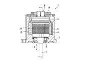
図1は、この発明の実施の形態1に係るモータの構造を示す図である。
図1では、ステータを断面で示し、このステータ内に配置されるロータおよび回転軸等を側面視で示している。
モータ1は、固定子であるステータ2およびステータ2の内周側に回転可能に配置された回転子である円筒形状のロータ3を備える。ステータ2は、内周側に複数貼り付けられたマグネット4と、マグネット4の外周面に配設された円筒状の磁性体で形成されたヨーク5とを備える。ステータ2は、モータ1のケースとしての機能も備える。
Embodiment 1 FIG.
1 is a diagram showing a structure of a motor according to Embodiment 1 of the present invention.
In FIG. 1, the stator is shown in a cross section, and the rotor, the rotating shaft, and the like arranged in the stator are shown in side view.
The motor 1 includes a
回転子であるロータ3は、円環状のロータコア31と、ロータコア31に巻き回されるコイル(図示しない)、当該コイルに接続された整流子6等を備える。ロータ3の中央部に設けた中央穴にはネジ部が形成され、このネジ部に螺合させて回転軸7が挿通される。回転軸7は、ステータ2に対して設けられた軸受8に軸受けされる。ロータ3がマグネット4の内周側で回転することにより、ロータ3に形成されたネジ部に螺合する回転軸7が直動方向Xに移動する。
The
また、モータ1には、整流子6を介してロータ3に電源を供給するブラシ9、ブラシ9に電源を供給する電源供給端子部(図示しない)等が配置されている。ロータ3に電源を供給する際に、回転軸7の端部に設けられた整流子6にブラシ9が摺接する。ブラシ9は、回転する整流子6に摺接するため、摩耗が起こり、摩耗粉が発生する。図1に示すように、ロータコア31の外周面と、マグネット4の内周面との間には、クリアランス領域10として所定のクリアランスが形成されている。発生したブラシ9の摩耗粉が、このクリアランス領域10内に侵入すると、ロータ3の回転が阻害される。
Further, the motor 1 is provided with a brush 9 that supplies power to the
次に、ブラシ9の摩耗粉がクリアランス領域10に侵入するのを防止する構造について、図1、図2および図3を参照しながら説明する。
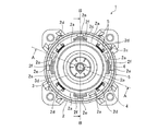
図2は、実施の形態1に係るモータの上面図である。
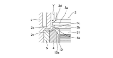
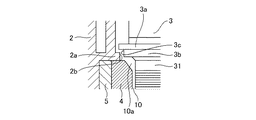
図3は、図2のA−A線断面図の一部を示した図である。
まず、図1および図3を参照しながら、ロータ3とステータ2により構成されたラビリンス構造について説明する。なお、図3の矢印Yは摩耗粉の侵入経路を示している。
ロータ3は、ロータコア31の上部に、外周方向、即ちステータ2側に突出する円環状の第1の突起部3aを有している。ロータ3をステータ2内に配設した際に、第1の突起部3aは、クリアランス領域10の開口領域10aを周方向に覆う。また、第1の突起部3aは、マグネット4の上面の少なくとも一部を周方向に覆う。
Next, a structure for preventing the abrasion powder of the brush 9 from entering the
FIG. 2 is a top view of the motor according to the first embodiment.
FIG. 3 is a diagram showing a part of a cross-sectional view taken along line AA of FIG.
First, a labyrinth structure constituted by the
The
第1の突起部3aのロータコア31側の面に、第1の突起部3aよりも円周が小さい円環状の部材3bを配置し、第1の突起部3aの外周形状と、円環状の部材3bの外周形状とにより、円環状の第1の段差部3cが形成される。ステータ2側には、マグネット4の上方、且つ第1の突起部の下方の領域に向けて突出する第2の突起部2aが形成される。この第2の突起部2aと、マグネット4の上面4aの形状とにより、第2の段差部2bが形成される。ロータ3側の第1の段差部3cの面と、ステータ2側の第2の段差部2bの面との間の領域に、ラビリンス構造が形成される。形成されたラビリンス構造により、開口領域10aおよびクリアランス領域10への摩耗粉の進入を防止することができる。
また、第1の突起部3aの整流子6側の面には、円環状の第1の突起部3aの中心から外周方向に向けて、第1の突起部3aの厚みが減少するテーパ部3dが形成される。テーパ部3dは、ブラシ9の摩耗粉を後述する穴部に誘導する。
An
Further, on the surface of the
次に、図2を参照しながら、ステータ2に形成した摩耗粉を堆積させる穴部の構造について説明する。
図2は、ロータ3をステータ2内に配設したモータ1の上面図である。
図2に示すように、上述した第2の突起部2aは、ステータ2の内周側且つ周方向に所定の間隔で均等に複数形成されている。2つの第2の突起部2aの間には、凹部2cが形成される。ロータ3をステータ2内に配設した場合に、ロータ3の第1の突起部3aと、複数の凹部2cとにより、第1の突起部3aの外周部に複数の開口部が、所定の間隔で均等に形成される。この複数の開口部の下方に、複数の穴部2d,2e,2fが形成されている。穴部2dは、マグネット4の外周面側に形成される。穴部2eはヨーク5の外周面側に形成され、穴部2fはヨーク5の内周面側に形成される。
Next, the structure of the hole for depositing the wear powder formed on the
FIG. 2 is a top view of the motor 1 in which the
As shown in FIG. 2, a plurality of the
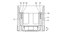
穴部2d,2e,2fの深さ方向の形状を図4に示す。
図4は、図2のB−B線断面図であり、ステータ2のみを示した図である。また、図4は、穴部2e,2fの形状を示している。
穴部2e,2fは、回転軸7(図4では図示を省略)の直動方向Xの方向に深さを有する穴部である。図4に示すように、穴部2eはヨーク5の外周側に形成され、穴部2fはヨーク5の内周側に形成されている。穴部2e,2fの深さは、ブラシ9の大きさに応じて発生すると推定される摩耗粉の量に応じて適宜設計される。
図示は省略するが、穴部2dも同様に、回転軸7の直動方向Xの方向に深さを有し、その深さはブラシ9の大きさに応じて適宜設計される。
The shape of the
FIG. 4 is a cross-sectional view taken along the line BB of FIG. 2 and shows only the
The
Although illustration is omitted, the
ロータ3の第1の突起部3aの上面に落下したブラシ9の摩耗粉は、テーパ部3dを経由して、穴部2d,2e,2fに落ちて堆積する。
第1の突起部3aがクリアランス領域10の開口領域10aを覆い、さらにロータ3側の第1の段差部3cの面と、ステータ2側の第2の段差部2bの面との間の領域にラビリンス構造が形成され、ロータ3の第1の突起部3aの上面に落下した摩耗粉がクリアランス領域10に侵入するのを防止することができる。さらに、ステータ2の内周側に所定の間隔で形成された穴部2d,2e,2fに摩耗粉を集めることができる。
The abrasion powder of the brush 9 that has dropped onto the upper surface of the
The
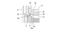
図5および図6は、実施の形態1に係るモータ1の第1の突起部のその他の形状を示す図である。
上述した説明では、第1の突起部3aの整流子6側の面に、テーパ部3dを形成する構成を示したが、第1の突起部3aの整流子6側の面形状は適宜設計可能である。例えば、図5に示すように、第1の突起部3aの整流子6側の面は平面であってもよい。なお、ロータ3側の第1の段差部3cの面と、ステータ2側の第2の段差部2bの面との間の領域にはラビリンス構造が形成されている。
5 and 6 are diagrams showing other shapes of the first protrusion of the motor 1 according to the first embodiment.
In the above description, the configuration in which the tapered
また、図6に示すように、第1の突起部3aの外周端部に、整流子6側に突出する円環状部材3eを設け、第1の突起部3aおよび円環状部材3eの断面形状をL字形状としてもよい。図6では、第1の突起部3aおよび円環状部材3eを断面で示している。断面形状がL字形状となるよう第1の突起部3aおよび円環状部材3eを形成することにより、L字形状の領域で摩耗粉を受け止め、さらにロータ3側の第1の段差部3cの面と、ステータ2側の第2の段差部2bの面との間の領域に形成されたラビリンス構造により、ブラシ9の摩耗粉がクリアランス領域10に侵入するのを防止することができる。
Further, as shown in FIG. 6, an
以上のように、この実施の形態1によれば、マグネット4が設けられた円筒形状のステータ2と、マグネット4の内側に回転可能に配置された円筒形状のロータコア31と、ロータコア31に巻き回されたコイルと、当該コイルに接続された整流子6とを有するロータ3と、整流子6と摺接してロータ3に電力を供給するブラシ9とを備え、ロータ3は、ロータコア31とブラシ9との間に、ステータ2側に突出する円環状の第1の突起部3aを有し、ステータ2は、第1の突起部3aと、マグネット4のブラシ9側の面との間の領域に突出する第2の突起部2aを周方向に複数有し、且つ周方向に隣り合う2つの第2の突起部2aの間に穴部2d,2e,2fを有し、第1の突起部3aの面と、第2の突起部2aの面との間の領域が、ラビリンス構造を有するように構成したので、ブラシの摩耗粉がロータコアの外周面とマグネットの内周面との間のクリアランス領域に侵入してロータの回転を阻害するのを防止することができる。
As described above, according to the first embodiment, the
また、この実施の形態1によれば、第1の突起部3aは、ロータコア側の面に円環状の第1の段差部3cを有し、第1の段差部3cの面と、第2の突起部2aおよびマグネット4のブラシ9側の面とによって形成される第2の段差部2bの面との間の領域が、ラビリンス構造を形成するように構成したので、ブラシの摩耗粉がクリアランス領域に侵入するのを防止することができる。
Further, according to the first embodiment, the
また、この実施の形態1によれば、第1の突起部3aは、ブラシ9側の面に、中心から外周方向に向けて厚みが減少するテーパ部3dを有するように構成したので、ブラシの摩耗粉を穴部に効率よく集めることができる。
Further, according to the first embodiment, the
また、この実施の形態1によれば、ブラシ9の摩耗粉を堆積させる複数の穴部2d,2e,2fをステータ2の周方向に均等に配置したので、モータの搭載姿勢が制限されることがない。
Further, according to the first embodiment, since the plurality of
なお、本願発明はその発明の範囲内において、実施の形態の任意の構成要素の変形、もしくは実施の形態の任意の構成要素の省略が可能である。 In the present invention, any constituent element of the embodiment can be modified or any constituent element of the embodiment can be omitted within the scope of the invention.
1 モータ、2 ステータ、2a 第2の突起部、2b 第2の段差部、2c 開口部、2d,2e,2f 穴部、3 ロータ、3a 第1の突起部、3b 円環状の突起部、3c 第1の段差部、3d テーパ部、3e 円環状部材、4 マグネット、5 ヨーク、6 整流子、7 回転軸、8 軸受、9 ブラシ、10 クリアランス領域、10a 開口領域、31 ロータコア。 DESCRIPTION OF SYMBOLS 1 Motor, 2 Stator, 2a 2nd protrusion part, 2b 2nd level | step difference part, 2c opening part, 2d, 2e, 2f hole part, 3 rotor, 3a 1st protrusion part, 3b Toroidal protrusion part, 3c 1st step part, 3d taper part, 3e annular member, 4 magnet, 5 yoke, 6 commutator, 7 rotating shaft, 8 bearing, 9 brush, 10 clearance area, 10a opening area, 31 rotor core.
Claims (4)
前記ステータの前記マグネットの内側に回転可能に配置された円筒形状のロータコアと、前記ロータコアに巻き回されたコイルと、当該コイルに接続された整流子とを有するロータと、
前記整流子と摺接して前記ロータに電力を供給するブラシとを備え、
前記ロータは、前記ロータコアと前記ブラシとの間に、前記ステータ側に突出する円環状の第1の突起部を有し、
前記ステータは、前記第1の突起部と、前記マグネットの前記ブラシ側の面との間の領域に突出する第2の突起部を周方向に複数有し、且つ前記周方向に隣り合う2つの前記第2の突起部の間に穴部を有し、
前記第1の突起部の面と、前記第2の突起部の面との間の領域が、ラビリンス構造を有するモータ。 A cylindrical stator provided with a magnet;
A rotor having a cylindrical rotor core rotatably disposed inside the magnet of the stator, a coil wound around the rotor core, and a commutator connected to the coil;
A brush that slidably contacts the commutator and supplies power to the rotor;
The rotor has an annular first protrusion that protrudes toward the stator between the rotor core and the brush,
The stator has a plurality of second protrusions projecting in a region between the first projection and the brush-side surface of the magnet in the circumferential direction, and two adjacent in the circumferential direction. Having a hole between the second protrusions;
A motor having a labyrinth structure in a region between a surface of the first protrusion and a surface of the second protrusion.
前記第1の段差部の面と、前記第2の突起部および前記マグネットの前記ブラシ側の面とによって形成される第2の段差部の面との間の領域が、前記ラビリンス構造を形成する請求項1記載のモータ。 The first protrusion has an annular first step portion on the rotor core side surface,
A region between the surface of the first step portion and the surface of the second step portion formed by the second protrusion and the brush-side surface of the magnet forms the labyrinth structure. The motor according to claim 1.
Priority Applications (1)
| Application Number | Priority Date | Filing Date | Title |
|---|---|---|---|
| JP2016090774A JP6552451B2 (en) | 2016-04-28 | 2016-04-28 | motor |
Applications Claiming Priority (1)
| Application Number | Priority Date | Filing Date | Title |
|---|---|---|---|
| JP2016090774A JP6552451B2 (en) | 2016-04-28 | 2016-04-28 | motor |
Publications (2)
| Publication Number | Publication Date |
|---|---|
| JP2017200367A true JP2017200367A (en) | 2017-11-02 |
| JP6552451B2 JP6552451B2 (en) | 2019-07-31 |
Family
ID=60239675
Family Applications (1)
| Application Number | Title | Priority Date | Filing Date |
|---|---|---|---|
| JP2016090774A Expired - Fee Related JP6552451B2 (en) | 2016-04-28 | 2016-04-28 | motor |
Country Status (1)
| Country | Link |
|---|---|
| JP (1) | JP6552451B2 (en) |
Citations (8)
| Publication number | Priority date | Publication date | Assignee | Title |
|---|---|---|---|---|
| JPS60162968U (en) * | 1984-04-05 | 1985-10-29 | 松下電器産業株式会社 | commutator motor |
| JPH07213032A (en) * | 1994-01-25 | 1995-08-11 | Hitachi Ltd | Vehicle alternator |
| JP2003333791A (en) * | 2002-05-17 | 2003-11-21 | Meidensha Corp | Permanent magnet electric rotating machine |
| US20060175925A1 (en) * | 2005-02-08 | 2006-08-10 | Michael Coles | Motor assembly with a sealed commutator/brush interface |
| US20080030098A1 (en) * | 2006-08-02 | 2008-02-07 | Shawcross James P | Motor assembly with a sealed commutator/brush interface |
| JP2012175841A (en) * | 2011-02-22 | 2012-09-10 | Jtekt Corp | Electric motor with brush and electric power steering device |
| JP2014226021A (en) * | 2013-04-22 | 2014-12-04 | アスモ株式会社 | Motor |
| CN204669170U (en) * | 2013-09-17 | 2015-09-23 | 松下知识产权经营株式会社 | Brush motor |
-
2016
- 2016-04-28 JP JP2016090774A patent/JP6552451B2/en not_active Expired - Fee Related
Patent Citations (8)
| Publication number | Priority date | Publication date | Assignee | Title |
|---|---|---|---|---|
| JPS60162968U (en) * | 1984-04-05 | 1985-10-29 | 松下電器産業株式会社 | commutator motor |
| JPH07213032A (en) * | 1994-01-25 | 1995-08-11 | Hitachi Ltd | Vehicle alternator |
| JP2003333791A (en) * | 2002-05-17 | 2003-11-21 | Meidensha Corp | Permanent magnet electric rotating machine |
| US20060175925A1 (en) * | 2005-02-08 | 2006-08-10 | Michael Coles | Motor assembly with a sealed commutator/brush interface |
| US20080030098A1 (en) * | 2006-08-02 | 2008-02-07 | Shawcross James P | Motor assembly with a sealed commutator/brush interface |
| JP2012175841A (en) * | 2011-02-22 | 2012-09-10 | Jtekt Corp | Electric motor with brush and electric power steering device |
| JP2014226021A (en) * | 2013-04-22 | 2014-12-04 | アスモ株式会社 | Motor |
| CN204669170U (en) * | 2013-09-17 | 2015-09-23 | 松下知识产权经营株式会社 | Brush motor |
Also Published As
| Publication number | Publication date |
|---|---|
| JP6552451B2 (en) | 2019-07-31 |
Similar Documents
| Publication | Publication Date | Title |
|---|---|---|
| KR101493635B1 (en) | Fan motor | |
| JP6357239B2 (en) | motor | |
| CN103580357B (en) | Brushless electric machine | |
| JP2019112998A (en) | Air blower | |
| KR20120118756A (en) | Brushless direct current motor | |
| JP2016165198A (en) | Rotating machine waterproof structure and rotating machine | |
| US20160268863A1 (en) | Brushless motor | |
| KR20160089784A (en) | Housing and Motor having the same | |
| JP6552451B2 (en) | motor | |
| JP6113446B2 (en) | Electric motor | |
| CN107925302B (en) | Shell and motor comprising same | |
| JP6243379B2 (en) | motor | |
| CN206341109U (en) | Motor | |
| JP2018198503A (en) | motor | |
| EP3364527B1 (en) | Electric motor and blower | |
| JP5860724B2 (en) | Outer rotor type brushless motor | |
| JP2017005934A (en) | DC motor | |
| KR20200032506A (en) | Stator and motor assembly comprising the same | |
| JP4268451B2 (en) | motor | |
| JP6553153B2 (en) | motor | |
| KR102621847B1 (en) | Cover assembly and Motor having the same | |
| KR101086930B1 (en) | Rotating device that can prevent axial flow of rotor | |
| JP2019122059A (en) | Brushed motor, and fan motor for radiator cooling | |
| JPWO2018105046A1 (en) | Permanent magnet rotating electric machine | |
| JP7090874B2 (en) | Commutator and brushed motor with this commutator |
Legal Events
| Date | Code | Title | Description |
|---|---|---|---|
| A621 | Written request for application examination |
Free format text: JAPANESE INTERMEDIATE CODE: A621 Effective date: 20180821 |
|
| A977 | Report on retrieval |
Free format text: JAPANESE INTERMEDIATE CODE: A971007 Effective date: 20190522 |
|
| TRDD | Decision of grant or rejection written | ||
| A01 | Written decision to grant a patent or to grant a registration (utility model) |
Free format text: JAPANESE INTERMEDIATE CODE: A01 Effective date: 20190604 |
|
| A61 | First payment of annual fees (during grant procedure) |
Free format text: JAPANESE INTERMEDIATE CODE: A61 Effective date: 20190702 |
|
| R150 | Certificate of patent or registration of utility model |
Ref document number: 6552451 Country of ref document: JP Free format text: JAPANESE INTERMEDIATE CODE: R150 |
|
| LAPS | Cancellation because of no payment of annual fees |