JP2017200272A - Power management system, battery management unit, battery unit, and power management method for vehicle - Google Patents
Power management system, battery management unit, battery unit, and power management method for vehicle Download PDFInfo
- Publication number
- JP2017200272A JP2017200272A JP2016087800A JP2016087800A JP2017200272A JP 2017200272 A JP2017200272 A JP 2017200272A JP 2016087800 A JP2016087800 A JP 2016087800A JP 2016087800 A JP2016087800 A JP 2016087800A JP 2017200272 A JP2017200272 A JP 2017200272A
- Authority
- JP
- Japan
- Prior art keywords
- vehicle
- power
- current
- secondary battery
- load
- Prior art date
- Legal status (The legal status is an assumption and is not a legal conclusion. Google has not performed a legal analysis and makes no representation as to the accuracy of the status listed.)
- Granted
Links
Images


Classifications
-
- B—PERFORMING OPERATIONS; TRANSPORTING
- B60—VEHICLES IN GENERAL
- B60L—PROPULSION OF ELECTRICALLY-PROPELLED VEHICLES; SUPPLYING ELECTRIC POWER FOR AUXILIARY EQUIPMENT OF ELECTRICALLY-PROPELLED VEHICLES; ELECTRODYNAMIC BRAKE SYSTEMS FOR VEHICLES IN GENERAL; MAGNETIC SUSPENSION OR LEVITATION FOR VEHICLES; MONITORING OPERATING VARIABLES OF ELECTRICALLY-PROPELLED VEHICLES; ELECTRIC SAFETY DEVICES FOR ELECTRICALLY-PROPELLED VEHICLES
- B60L3/00—Electric devices on electrically-propelled vehicles for safety purposes; Monitoring operating variables, e.g. speed, deceleration or energy consumption
- B60L3/0023—Detecting, eliminating, remedying or compensating for drive train abnormalities, e.g. failures within the drive train
- B60L3/0046—Detecting, eliminating, remedying or compensating for drive train abnormalities, e.g. failures within the drive train relating to electric energy storage systems, e.g. batteries or capacitors
-
- B—PERFORMING OPERATIONS; TRANSPORTING
- B60—VEHICLES IN GENERAL
- B60L—PROPULSION OF ELECTRICALLY-PROPELLED VEHICLES; SUPPLYING ELECTRIC POWER FOR AUXILIARY EQUIPMENT OF ELECTRICALLY-PROPELLED VEHICLES; ELECTRODYNAMIC BRAKE SYSTEMS FOR VEHICLES IN GENERAL; MAGNETIC SUSPENSION OR LEVITATION FOR VEHICLES; MONITORING OPERATING VARIABLES OF ELECTRICALLY-PROPELLED VEHICLES; ELECTRIC SAFETY DEVICES FOR ELECTRICALLY-PROPELLED VEHICLES
- B60L3/00—Electric devices on electrically-propelled vehicles for safety purposes; Monitoring operating variables, e.g. speed, deceleration or energy consumption
- B60L3/04—Cutting off the power supply under fault conditions
-
- B—PERFORMING OPERATIONS; TRANSPORTING
- B60—VEHICLES IN GENERAL
- B60L—PROPULSION OF ELECTRICALLY-PROPELLED VEHICLES; SUPPLYING ELECTRIC POWER FOR AUXILIARY EQUIPMENT OF ELECTRICALLY-PROPELLED VEHICLES; ELECTRODYNAMIC BRAKE SYSTEMS FOR VEHICLES IN GENERAL; MAGNETIC SUSPENSION OR LEVITATION FOR VEHICLES; MONITORING OPERATING VARIABLES OF ELECTRICALLY-PROPELLED VEHICLES; ELECTRIC SAFETY DEVICES FOR ELECTRICALLY-PROPELLED VEHICLES
- B60L50/00—Electric propulsion with power supplied within the vehicle
- B60L50/10—Electric propulsion with power supplied within the vehicle using propulsion power supplied by engine-driven generators, e.g. generators driven by combustion engines
- B60L50/15—Electric propulsion with power supplied within the vehicle using propulsion power supplied by engine-driven generators, e.g. generators driven by combustion engines with additional electric power supply
-
- B—PERFORMING OPERATIONS; TRANSPORTING
- B60—VEHICLES IN GENERAL
- B60L—PROPULSION OF ELECTRICALLY-PROPELLED VEHICLES; SUPPLYING ELECTRIC POWER FOR AUXILIARY EQUIPMENT OF ELECTRICALLY-PROPELLED VEHICLES; ELECTRODYNAMIC BRAKE SYSTEMS FOR VEHICLES IN GENERAL; MAGNETIC SUSPENSION OR LEVITATION FOR VEHICLES; MONITORING OPERATING VARIABLES OF ELECTRICALLY-PROPELLED VEHICLES; ELECTRIC SAFETY DEVICES FOR ELECTRICALLY-PROPELLED VEHICLES
- B60L50/00—Electric propulsion with power supplied within the vehicle
- B60L50/10—Electric propulsion with power supplied within the vehicle using propulsion power supplied by engine-driven generators, e.g. generators driven by combustion engines
- B60L50/16—Electric propulsion with power supplied within the vehicle using propulsion power supplied by engine-driven generators, e.g. generators driven by combustion engines with provision for separate direct mechanical propulsion
-
- B—PERFORMING OPERATIONS; TRANSPORTING
- B60—VEHICLES IN GENERAL
- B60L—PROPULSION OF ELECTRICALLY-PROPELLED VEHICLES; SUPPLYING ELECTRIC POWER FOR AUXILIARY EQUIPMENT OF ELECTRICALLY-PROPELLED VEHICLES; ELECTRODYNAMIC BRAKE SYSTEMS FOR VEHICLES IN GENERAL; MAGNETIC SUSPENSION OR LEVITATION FOR VEHICLES; MONITORING OPERATING VARIABLES OF ELECTRICALLY-PROPELLED VEHICLES; ELECTRIC SAFETY DEVICES FOR ELECTRICALLY-PROPELLED VEHICLES
- B60L58/00—Methods or circuit arrangements for monitoring or controlling batteries or fuel cells, specially adapted for electric vehicles
- B60L58/10—Methods or circuit arrangements for monitoring or controlling batteries or fuel cells, specially adapted for electric vehicles for monitoring or controlling batteries
-
- H—ELECTRICITY
- H02—GENERATION; CONVERSION OR DISTRIBUTION OF ELECTRIC POWER
- H02J—CIRCUIT ARRANGEMENTS OR SYSTEMS FOR SUPPLYING OR DISTRIBUTING ELECTRIC POWER; SYSTEMS FOR STORING ELECTRIC ENERGY
- H02J7/00—Circuit arrangements for charging or depolarising batteries or for supplying loads from batteries
- H02J7/0029—Circuit arrangements for charging or depolarising batteries or for supplying loads from batteries with safety or protection devices or circuits
- H02J7/0031—Circuit arrangements for charging or depolarising batteries or for supplying loads from batteries with safety or protection devices or circuits using battery or load disconnect circuits
-
- H—ELECTRICITY
- H02—GENERATION; CONVERSION OR DISTRIBUTION OF ELECTRIC POWER
- H02J—CIRCUIT ARRANGEMENTS OR SYSTEMS FOR SUPPLYING OR DISTRIBUTING ELECTRIC POWER; SYSTEMS FOR STORING ELECTRIC ENERGY
- H02J7/00—Circuit arrangements for charging or depolarising batteries or for supplying loads from batteries
- H02J7/0029—Circuit arrangements for charging or depolarising batteries or for supplying loads from batteries with safety or protection devices or circuits
- H02J7/0036—Circuit arrangements for charging or depolarising batteries or for supplying loads from batteries with safety or protection devices or circuits using connection detecting circuits
-
- H—ELECTRICITY
- H02—GENERATION; CONVERSION OR DISTRIBUTION OF ELECTRIC POWER
- H02J—CIRCUIT ARRANGEMENTS OR SYSTEMS FOR SUPPLYING OR DISTRIBUTING ELECTRIC POWER; SYSTEMS FOR STORING ELECTRIC ENERGY
- H02J7/00—Circuit arrangements for charging or depolarising batteries or for supplying loads from batteries
- H02J7/0068—Battery or charger load switching, e.g. concurrent charging and load supply
-
- H—ELECTRICITY
- H02—GENERATION; CONVERSION OR DISTRIBUTION OF ELECTRIC POWER
- H02J—CIRCUIT ARRANGEMENTS OR SYSTEMS FOR SUPPLYING OR DISTRIBUTING ELECTRIC POWER; SYSTEMS FOR STORING ELECTRIC ENERGY
- H02J7/00—Circuit arrangements for charging or depolarising batteries or for supplying loads from batteries
- H02J7/14—Circuit arrangements for charging or depolarising batteries or for supplying loads from batteries for charging batteries from dynamo-electric generators driven at varying speed, e.g. on vehicle
-
- B—PERFORMING OPERATIONS; TRANSPORTING
- B60—VEHICLES IN GENERAL
- B60L—PROPULSION OF ELECTRICALLY-PROPELLED VEHICLES; SUPPLYING ELECTRIC POWER FOR AUXILIARY EQUIPMENT OF ELECTRICALLY-PROPELLED VEHICLES; ELECTRODYNAMIC BRAKE SYSTEMS FOR VEHICLES IN GENERAL; MAGNETIC SUSPENSION OR LEVITATION FOR VEHICLES; MONITORING OPERATING VARIABLES OF ELECTRICALLY-PROPELLED VEHICLES; ELECTRIC SAFETY DEVICES FOR ELECTRICALLY-PROPELLED VEHICLES
- B60L2240/00—Control parameters of input or output; Target parameters
- B60L2240/40—Drive Train control parameters
- B60L2240/44—Drive Train control parameters related to combustion engines
- B60L2240/441—Speed
-
- B—PERFORMING OPERATIONS; TRANSPORTING
- B60—VEHICLES IN GENERAL
- B60L—PROPULSION OF ELECTRICALLY-PROPELLED VEHICLES; SUPPLYING ELECTRIC POWER FOR AUXILIARY EQUIPMENT OF ELECTRICALLY-PROPELLED VEHICLES; ELECTRODYNAMIC BRAKE SYSTEMS FOR VEHICLES IN GENERAL; MAGNETIC SUSPENSION OR LEVITATION FOR VEHICLES; MONITORING OPERATING VARIABLES OF ELECTRICALLY-PROPELLED VEHICLES; ELECTRIC SAFETY DEVICES FOR ELECTRICALLY-PROPELLED VEHICLES
- B60L2240/00—Control parameters of input or output; Target parameters
- B60L2240/40—Drive Train control parameters
- B60L2240/54—Drive Train control parameters related to batteries
- B60L2240/545—Temperature
-
- B—PERFORMING OPERATIONS; TRANSPORTING
- B60—VEHICLES IN GENERAL
- B60L—PROPULSION OF ELECTRICALLY-PROPELLED VEHICLES; SUPPLYING ELECTRIC POWER FOR AUXILIARY EQUIPMENT OF ELECTRICALLY-PROPELLED VEHICLES; ELECTRODYNAMIC BRAKE SYSTEMS FOR VEHICLES IN GENERAL; MAGNETIC SUSPENSION OR LEVITATION FOR VEHICLES; MONITORING OPERATING VARIABLES OF ELECTRICALLY-PROPELLED VEHICLES; ELECTRIC SAFETY DEVICES FOR ELECTRICALLY-PROPELLED VEHICLES
- B60L2240/00—Control parameters of input or output; Target parameters
- B60L2240/40—Drive Train control parameters
- B60L2240/54—Drive Train control parameters related to batteries
- B60L2240/547—Voltage
-
- B—PERFORMING OPERATIONS; TRANSPORTING
- B60—VEHICLES IN GENERAL
- B60L—PROPULSION OF ELECTRICALLY-PROPELLED VEHICLES; SUPPLYING ELECTRIC POWER FOR AUXILIARY EQUIPMENT OF ELECTRICALLY-PROPELLED VEHICLES; ELECTRODYNAMIC BRAKE SYSTEMS FOR VEHICLES IN GENERAL; MAGNETIC SUSPENSION OR LEVITATION FOR VEHICLES; MONITORING OPERATING VARIABLES OF ELECTRICALLY-PROPELLED VEHICLES; ELECTRIC SAFETY DEVICES FOR ELECTRICALLY-PROPELLED VEHICLES
- B60L2240/00—Control parameters of input or output; Target parameters
- B60L2240/40—Drive Train control parameters
- B60L2240/54—Drive Train control parameters related to batteries
- B60L2240/549—Current
-
- B—PERFORMING OPERATIONS; TRANSPORTING
- B60—VEHICLES IN GENERAL
- B60L—PROPULSION OF ELECTRICALLY-PROPELLED VEHICLES; SUPPLYING ELECTRIC POWER FOR AUXILIARY EQUIPMENT OF ELECTRICALLY-PROPELLED VEHICLES; ELECTRODYNAMIC BRAKE SYSTEMS FOR VEHICLES IN GENERAL; MAGNETIC SUSPENSION OR LEVITATION FOR VEHICLES; MONITORING OPERATING VARIABLES OF ELECTRICALLY-PROPELLED VEHICLES; ELECTRIC SAFETY DEVICES FOR ELECTRICALLY-PROPELLED VEHICLES
- B60L2250/00—Driver interactions
- B60L2250/10—Driver interactions by alarm
-
- B—PERFORMING OPERATIONS; TRANSPORTING
- B60—VEHICLES IN GENERAL
- B60L—PROPULSION OF ELECTRICALLY-PROPELLED VEHICLES; SUPPLYING ELECTRIC POWER FOR AUXILIARY EQUIPMENT OF ELECTRICALLY-PROPELLED VEHICLES; ELECTRODYNAMIC BRAKE SYSTEMS FOR VEHICLES IN GENERAL; MAGNETIC SUSPENSION OR LEVITATION FOR VEHICLES; MONITORING OPERATING VARIABLES OF ELECTRICALLY-PROPELLED VEHICLES; ELECTRIC SAFETY DEVICES FOR ELECTRICALLY-PROPELLED VEHICLES
- B60L50/00—Electric propulsion with power supplied within the vehicle
- B60L50/50—Electric propulsion with power supplied within the vehicle using propulsion power supplied by batteries or fuel cells
- B60L50/60—Electric propulsion with power supplied within the vehicle using propulsion power supplied by batteries or fuel cells using power supplied by batteries
- B60L50/61—Electric propulsion with power supplied within the vehicle using propulsion power supplied by batteries or fuel cells using power supplied by batteries by batteries charged by engine-driven generators, e.g. series hybrid electric vehicles
-
- B—PERFORMING OPERATIONS; TRANSPORTING
- B60—VEHICLES IN GENERAL
- B60L—PROPULSION OF ELECTRICALLY-PROPELLED VEHICLES; SUPPLYING ELECTRIC POWER FOR AUXILIARY EQUIPMENT OF ELECTRICALLY-PROPELLED VEHICLES; ELECTRODYNAMIC BRAKE SYSTEMS FOR VEHICLES IN GENERAL; MAGNETIC SUSPENSION OR LEVITATION FOR VEHICLES; MONITORING OPERATING VARIABLES OF ELECTRICALLY-PROPELLED VEHICLES; ELECTRIC SAFETY DEVICES FOR ELECTRICALLY-PROPELLED VEHICLES
- B60L58/00—Methods or circuit arrangements for monitoring or controlling batteries or fuel cells, specially adapted for electric vehicles
- B60L58/10—Methods or circuit arrangements for monitoring or controlling batteries or fuel cells, specially adapted for electric vehicles for monitoring or controlling batteries
- B60L58/24—Methods or circuit arrangements for monitoring or controlling batteries or fuel cells, specially adapted for electric vehicles for monitoring or controlling batteries for controlling the temperature of batteries
-
- H—ELECTRICITY
- H02—GENERATION; CONVERSION OR DISTRIBUTION OF ELECTRIC POWER
- H02J—CIRCUIT ARRANGEMENTS OR SYSTEMS FOR SUPPLYING OR DISTRIBUTING ELECTRIC POWER; SYSTEMS FOR STORING ELECTRIC ENERGY
- H02J7/00—Circuit arrangements for charging or depolarising batteries or for supplying loads from batteries
- H02J7/0029—Circuit arrangements for charging or depolarising batteries or for supplying loads from batteries with safety or protection devices or circuits
- H02J7/00302—Overcharge protection
-
- H—ELECTRICITY
- H02—GENERATION; CONVERSION OR DISTRIBUTION OF ELECTRIC POWER
- H02J—CIRCUIT ARRANGEMENTS OR SYSTEMS FOR SUPPLYING OR DISTRIBUTING ELECTRIC POWER; SYSTEMS FOR STORING ELECTRIC ENERGY
- H02J7/00—Circuit arrangements for charging or depolarising batteries or for supplying loads from batteries
- H02J7/0029—Circuit arrangements for charging or depolarising batteries or for supplying loads from batteries with safety or protection devices or circuits
- H02J7/00306—Overdischarge protection
-
- Y—GENERAL TAGGING OF NEW TECHNOLOGICAL DEVELOPMENTS; GENERAL TAGGING OF CROSS-SECTIONAL TECHNOLOGIES SPANNING OVER SEVERAL SECTIONS OF THE IPC; TECHNICAL SUBJECTS COVERED BY FORMER USPC CROSS-REFERENCE ART COLLECTIONS [XRACs] AND DIGESTS
- Y02—TECHNOLOGIES OR APPLICATIONS FOR MITIGATION OR ADAPTATION AGAINST CLIMATE CHANGE
- Y02T—CLIMATE CHANGE MITIGATION TECHNOLOGIES RELATED TO TRANSPORTATION
- Y02T10/00—Road transport of goods or passengers
- Y02T10/60—Other road transportation technologies with climate change mitigation effect
- Y02T10/62—Hybrid vehicles
-
- Y—GENERAL TAGGING OF NEW TECHNOLOGICAL DEVELOPMENTS; GENERAL TAGGING OF CROSS-SECTIONAL TECHNOLOGIES SPANNING OVER SEVERAL SECTIONS OF THE IPC; TECHNICAL SUBJECTS COVERED BY FORMER USPC CROSS-REFERENCE ART COLLECTIONS [XRACs] AND DIGESTS
- Y02—TECHNOLOGIES OR APPLICATIONS FOR MITIGATION OR ADAPTATION AGAINST CLIMATE CHANGE
- Y02T—CLIMATE CHANGE MITIGATION TECHNOLOGIES RELATED TO TRANSPORTATION
- Y02T10/00—Road transport of goods or passengers
- Y02T10/60—Other road transportation technologies with climate change mitigation effect
- Y02T10/70—Energy storage systems for electromobility, e.g. batteries
-
- Y—GENERAL TAGGING OF NEW TECHNOLOGICAL DEVELOPMENTS; GENERAL TAGGING OF CROSS-SECTIONAL TECHNOLOGIES SPANNING OVER SEVERAL SECTIONS OF THE IPC; TECHNICAL SUBJECTS COVERED BY FORMER USPC CROSS-REFERENCE ART COLLECTIONS [XRACs] AND DIGESTS
- Y02—TECHNOLOGIES OR APPLICATIONS FOR MITIGATION OR ADAPTATION AGAINST CLIMATE CHANGE
- Y02T—CLIMATE CHANGE MITIGATION TECHNOLOGIES RELATED TO TRANSPORTATION
- Y02T10/00—Road transport of goods or passengers
- Y02T10/60—Other road transportation technologies with climate change mitigation effect
- Y02T10/7072—Electromobility specific charging systems or methods for batteries, ultracapacitors, supercapacitors or double-layer capacitors
Abstract
Description
本明細書によって開示される技術は、電力管理システム、電池管理装置、バッテリ装置および車両の電力管理方法に関する。 The technology disclosed in the present specification relates to a power management system, a battery management device, a battery device, and a vehicle power management method.
例えば、車両に搭載された電池パックは、エンジン始動装置など様々な負荷への電力供給を行うと共に、車両発電機(オルタネータ)から充電により電力供給されている。この種の電池パックは、電池パック内部に二次電池を管理する電池管理装置や二次電池の電流を遮断する電流遮断装置を搭載したものがあり、電池管理装置が二次電池の異常を検出すると、電流遮断装置において二次電池の電流を遮断する。このような技術としては、特開2013−195183号公報(下記特許文献1)が知られている。 For example, a battery pack mounted on a vehicle supplies power to various loads such as an engine starter and is supplied with power from a vehicle generator (alternator). This type of battery pack includes a battery management device that manages the secondary battery inside the battery pack and a current interruption device that cuts off the current of the secondary battery. The battery management device detects an abnormality in the secondary battery. Then, the current interrupting device interrupts the current of the secondary battery. As such a technique, JP2013-195183A (Patent Document 1 below) is known.
ところで、上記の電池パックによると、電池管理装置が二次電池の異常を検出すると、二次電池を保護するために、電流遮断装置において二次電池の電流を遮断する。このため、負荷への電力供給は、車両発電機によってのみ行われる。 By the way, according to said battery pack, when a battery management apparatus detects abnormality of a secondary battery, in order to protect a secondary battery, the electric current of a secondary battery will be interrupted | blocked in a current interruption device. For this reason, the power supply to the load is performed only by the vehicle generator.
しかしながら、例えば、負荷の消費電量が車両発電機の発電量を超えると、発電電圧が低下してしまい、車両の走行や安全性などに必要な重要な負荷を安定して稼働させることができなくなってしまう。 However, for example, if the power consumption of the load exceeds the power generation amount of the vehicle generator, the generated voltage decreases, and it becomes impossible to stably operate an important load necessary for traveling and safety of the vehicle. End up.
本明細書では、負荷の動作が不安定になることを防ぎつつ、二次電池を保護する技術を開示する。 The present specification discloses a technique for protecting a secondary battery while preventing the operation of a load from becoming unstable.
本明細書によって開示される技術は、電力管理システムであって、二次電池と、前記二次電池に接続される発電機と、前記二次電池に接続されると共に前記発電機に接続され、前記二次電池および前記発電機の電力供給により稼働する負荷と、前記発電機から前記負荷への電力供給を制御する電力制御部と、前記二次電池の異常状態を検出する検出部と、前記二次電池と前記負荷との間の電流を遮断する電流遮断部と、前記検出部において異常状態が検出された後、前記電流遮断部において前記電流を遮断する前に前記電力制御部に対して前記電流を遮断することを事前予告する制御部と、を備え、前記電力制御部は、前記事前予告に基づいて前記発電機から前記負荷への電力供給を制御する構成とした。 The technology disclosed in the present specification is a power management system, which is a secondary battery, a generator connected to the secondary battery, and connected to the secondary battery and to the generator. A load that operates by supplying power from the secondary battery and the generator; a power control unit that controls power supply from the generator to the load; a detection unit that detects an abnormal state of the secondary battery; A current interrupting unit that interrupts a current between the secondary battery and the load; and after detecting an abnormal state in the detecting unit, before the current interrupting unit interrupts the current, And a control unit that pre-notifies that the current is cut off, and the power control unit controls power supply from the generator to the load based on the pre-notification.
本明細書によって開示される技術によれば、負荷の動作が不安定になることを防ぎつつ、電流を遮断して二次電池を保護することができる。 According to the technology disclosed in this specification, the secondary battery can be protected by interrupting the current while preventing the operation of the load from becoming unstable.
(本実施形態の概要)
初めに、本実施形態にて開示する車両の電力管理システムの概要について説明する。本実施形態の電力管理システムは、二次電池と、前記二次電池に接続される発電機と、前記二次電池に接続されると共に前記発電機に接続され、前記二次電池および前記発電機の電力供給により稼働する負荷と、前記発電機から前記負荷への電力供給を制御する電力制御部と、前記二次電池の異常状態を検出する検出部と、前記二次電池と前記負荷との間の電流を遮断する電流遮断部と、前記検出部において異常状態が検出された後、前記電流遮断部において電流を遮断する前に前記電力制御部に対して前記電流を遮断することを事前予告する制御部と、を備え、前記電力制御部は、前記事前予告に基づいて前記発電機から前記負荷への電力供給を制御する構成とした。
(Outline of this embodiment)
First, an outline of a vehicle power management system disclosed in the present embodiment will be described. The power management system of the present embodiment includes a secondary battery, a generator connected to the secondary battery, and connected to the secondary battery and to the generator. The secondary battery and the generator A load that operates by supplying power, a power control unit that controls power supply from the generator to the load, a detection unit that detects an abnormal state of the secondary battery, and the secondary battery and the load. A current interrupting unit that interrupts the current between, and an advance notice that the current control unit interrupts the current before the current interrupting unit interrupts the current after detecting an abnormal state in the detecting unit A control unit configured to control power supply from the generator to the load based on the advance notice.
また、本実施形態にて開示する二次電池の電池管理装置は、二次電池の異常状態を検出する検出部と、前記検出部において異常状態が検出された場合に、前記二次電池と前記二次電池に接続された負荷との間の電流を遮断状態に切り替える制御部と、を備え、前記制御部は、前記検出部において異常状態を検出した後、前記電流を遮断状態に切り替える前に、前記負荷への電力供給を制御する電力制御部に対して前記電流を遮断することを事前予告する構成とした。 In addition, the battery management device for a secondary battery disclosed in the present embodiment includes a detection unit that detects an abnormal state of the secondary battery, and when the abnormal state is detected in the detection unit, the secondary battery and the battery A control unit that switches a current between the load connected to the secondary battery to a cut-off state, and the control unit detects an abnormal state in the detection unit and then switches the current to a cut-off state. The power control unit that controls power supply to the load is configured to give advance notice that the current is cut off.
また、本実施形態にて開示するバッテリ装置は、車両に搭載されるバッテリ装置であって、二次電池と、前記二次電池の電池管理装置と、前記二次電池と前記負荷との間の電流を遮断する電流遮断部とを備え、前記制御部は、前記電流遮断部において前記電流を遮断状態に切り替える構成とした。 The battery device disclosed in the present embodiment is a battery device mounted on a vehicle, and is between a secondary battery, a battery management device for the secondary battery, and the secondary battery and the load. And a control unit configured to switch the current to a cut-off state in the current cut-off unit.
また、本実施形態にて開示する車両の制御方法は、二次電池の異常状態が検出された際に、車両に搭載された負荷と前記二次電池との間の電流を遮断する車両の制御方法であって、異常状態が検出された後、前記電流が遮断される前に、前記電流の遮断の事前予告がされる予告工程と、前記予告工程の前記事前予告により、前記車両に搭載された発電機から前記負荷への電力供給を制御する電力制御工程と、を含む構成とした。 Further, the vehicle control method disclosed in the present embodiment is a vehicle control method that interrupts a current between a load mounted on the vehicle and the secondary battery when an abnormal state of the secondary battery is detected. In the method, after an abnormal state is detected, before the current is interrupted, a prior notice step for interrupting the current is performed, and the vehicle is installed in the vehicle by the prior notice of the advance notice step. And a power control step for controlling power supply from the generator to the load.
これらのような構成によると、制御部において電流を遮断状態に切り替えて、負荷から二次電池が切り離される前に、制御部が電力制御部に事前予告する。したがって、事前予告を受けることで、電力制御部は、発電機を継続稼働させて、負荷の発電量を確保したり、優先度の低い負荷への電力制限をしたりすることができ、その後に、二次電池と負荷との間の電流を遮断することができる。これにより、重要な負荷の動作が不安定になることを防ぎつつ、電流を遮断して二次電池を保護することができる。 According to such a configuration, the control unit switches the current to the cut-off state, and the control unit notifies the power control unit in advance before the secondary battery is disconnected from the load. Therefore, by receiving the advance notice, the power control unit can continuously operate the generator to secure the power generation amount of the load or limit the power to the load with low priority. The current between the secondary battery and the load can be cut off. Thus, the secondary battery can be protected by interrupting the current while preventing the operation of an important load from becoming unstable.
本明細書によって開示される電力管理システムは、以下の構成としてもよい。
本明細書により開示される電力管理システムの一実施態様として、前記制御部は、前記検出部において検出される異常状態のレベルに合わせて、前記事前予告を複数回に亘って行う構成としてもよい。
The power management system disclosed by this specification is good also as the following structures.
As an embodiment of the power management system disclosed in the present specification, the control unit may perform the advance notice multiple times in accordance with the level of the abnormal state detected by the detection unit. Good.
このような構成によると、例えば、異常状態が検出された段階や異常状態のレベルが低い段階でまず1回目の事前予告を行い、異常状態のレベルが高くなった際に、再度事前予告を行うなど、異常状態の初期レベルから複数回に亘って事前予告がされるから、電力制御部において、発電機の発電量を増加させたり、優先度の低い負荷に対する電力制限をしたりするなど電力制御の準備を、異常状態のレベル(事前予告の回数)に応じて段階的に行うことができる。 According to such a configuration, for example, the first advance notice is given at the stage where an abnormal condition is detected or the level of the abnormal condition is low, and the advance notice is given again when the level of the abnormal condition becomes high. Since the advance notice is given several times from the initial level of the abnormal state, etc., power control such as increasing the power generation amount of the generator or limiting the power for low priority loads in the power control unit Can be prepared step by step in accordance with the level of abnormal condition (number of advance notices).
本明細書により開示される電力管理システムの一実施態様として、前記制御部は、前記検出部において異常状態が検出された場合に、前記電力制御部に所定の時間間隔で複数回に亘って前記事前予告する構成としてもよい。
このような構成によると、電流が遮断されるまで事前予告によってカウントダウンされるから、電力制御部において、事前予告の回数に応じて段階的に、発電機の稼働率を高くしたり、優先度の低い負荷に対する電力制限をしたりするなど電力制御の準備を行うことができる。
本明細書により開示される電力管理システムの一実施態様として、前記電力制御部は、前記事前予告を検出する度に前記負荷への電力供給を段階的に制御する構成としてもよい。
このような構成によると、電力制御の準備を段階的に進めることで、車両側に負担が集中することを防ぐことができる。
As one embodiment of the power management system disclosed in the present specification, the control unit is configured to provide the power control unit with a plurality of times at predetermined time intervals when an abnormal state is detected in the detection unit. It is good also as a structure notified in advance of an article.
According to such a configuration, it is counted down by advance notice until the current is interrupted, so in the power control unit, the generator operating rate is increased step by step according to the number of advance notices, It is possible to prepare for power control such as limiting power to a low load.
As an embodiment of the power management system disclosed in the present specification, the power control unit may control the power supply to the load in stages each time the advance notice is detected.
According to such a configuration, it is possible to prevent the load from being concentrated on the vehicle side by proceeding with the preparation for power control step by step.
本明細書により開示される電力管理システムの一実施態様として、前記制御部は、前記事前予告をした後に、前記検出部において異常状態が解消されたことが検出された場合には、前記電力制御部に対して前記電流の遮断を取り消す取消通知を行うようになっており、前記電力制御部は、前記取消通知により、前記事前予告に基づいて行った前記電力供給の制御をキャンセルする構成としてもよい。 As one embodiment of the power management system disclosed in the present specification, the control unit, after making the advance notice, if the detection unit detects that the abnormal state has been resolved, A cancellation notification for canceling the interruption of the current is performed to the control unit, and the power control unit is configured to cancel the control of the power supply performed based on the advance notice by the cancellation notification. It is good.
このような構成によると、検出部において二次電池の異常状態が解消されたことを検出した場合には、制御部は電力制御部に対して取消通知をすることで、電力制御部において、事前予告に基づいて行った制御をキャンセルする。つまり、電流を遮断する事前予告をしたものの、二次電池の異常状態が解消されたことで、電力管理システムを通常の状態に速やかに復帰させることができる。 According to such a configuration, when the detection unit detects that the abnormal state of the secondary battery has been eliminated, the control unit notifies the power control unit of cancellation, so that the power control unit Cancel the control performed based on the notice. In other words, the power management system can be quickly returned to the normal state because the abnormal state of the secondary battery has been eliminated, although the advance notice for cutting off the current has been made.
本明細書により開示される電力管理システムの一実施態様として、前記電力管理システムは、車両に搭載される電力管理システムであって、前記車両の走行状態を監視する車両監視部を備え、前記制御部は、前記車両監視部において検出された前記車両の走行状態に応じて前記電流の遮断の時期と前記事前予告の時期との間の時間間隔を決定する構成としてもよい。 As one embodiment of the power management system disclosed in this specification, the power management system is a power management system mounted on a vehicle, and includes a vehicle monitoring unit that monitors a running state of the vehicle, and the control The unit may be configured to determine a time interval between the current cutoff time and the advance notice time according to the traveling state of the vehicle detected by the vehicle monitoring unit.
例えば、車両の走行状態によっては車両を急に停止させることができない場合、負荷の動作が不安定になってしまう虞がある。ところが、このような構成によると、車両の走行状態に応じて、電流遮断の時期と事前予告の時期とを短く設定し、事前予告を早めに行うことで、運転手が余裕をもって対処できるようにすることができる。また、電力制御部においても余裕をもって電力制御することができる。 For example, when the vehicle cannot be stopped suddenly depending on the traveling state of the vehicle, the operation of the load may become unstable. However, according to such a configuration, according to the running state of the vehicle, the current interruption time and the advance notice time are set short, and the advance notice is made early so that the driver can cope with a margin. can do. Also, the power control unit can perform power control with a margin.
本明細書により開示される電力管理システムの一実施態様として、前記電力管理システムは、車両に搭載される電力管理システムであって、前記電力制御部は、前記車両に設けられた電子制御装置であり、前記車両内には、警告を行う警告発信部が設けられており、前記電子制御装置は、前記制御部からの前記事前予告により前記警告発信部において警告を行う構成としてもよい。
このような構成によると、事前予告が電子制御装置に伝えられ、負荷の制御を行う際に、警告発信部が警告をすることで、車両の使用者に対して注意を促すことができる。
As an embodiment of the power management system disclosed in this specification, the power management system is a power management system mounted on a vehicle, and the power control unit is an electronic control device provided in the vehicle. In addition, a warning transmission unit that performs a warning may be provided in the vehicle, and the electronic control device may perform a warning in the warning transmission unit based on the advance notice from the control unit.
According to such a configuration, the advance notice is transmitted to the electronic control device, and when the load is controlled, the warning transmission unit gives a warning, so that the vehicle user can be alerted.
本明細書により開示される電力管理システムの一実施態様として、前記電力管理システムは、車両に搭載される電力管理システムであって、前記発電機は、前記車両のエンジンの駆動に伴って稼働する車両発電機であり、前記電子制御部は、前記事前予告があった場合には、前記エンジンのアイドリングを一時的に停止するアイドリングストップを禁止する構成としてもよい。 As an embodiment of the power management system disclosed in the present specification, the power management system is a power management system mounted on a vehicle, and the generator operates in accordance with driving of an engine of the vehicle. The electronic control unit may be configured to prohibit idling stop that temporarily stops idling of the engine when the advance notice is given.
このような構成によると、アイドリングストップによってエンジンが停止し、発電機と二次電池の双方から電力供給がなくなって負荷が停止してしまうことを防ぐことができる。つまり、発電機によって負荷の発電量を確保し、負荷と二次電池との間の電流が遮断されても負荷の動作が不安定になることを防ぐことができる。 According to such a configuration, it is possible to prevent the engine from being stopped due to idling stop and the load from being stopped due to the absence of power supply from both the generator and the secondary battery. In other words, the power generation amount of the load can be secured by the generator, and the operation of the load can be prevented from becoming unstable even when the current between the load and the secondary battery is interrupted.
本明細書により開示される電力管理システムの一実施態様として、前記電力管理システムは、車両に搭載される電力管理システムであって、前記発電機は、前記車両のエンジンの駆動に伴って稼働する車両発電機であり、前記電力制御部は、前記事前予告があった場合には、前記車両発電機のフィールド電流を増加させる、もしくは、エンジンの駆動回転数を上げることで前記車両発電機の発電量を増加させる構成としてもよい。
このような構成によると、電力制御部が、車両発電機のフィールド電流を増加させ、発電電圧を高めることで発電量を増加させたり、電力制御部が、エンジンの駆動回転数を上げることで車両発電機の発電量を増加させることで負荷に電力を供給することができるから、二次電池から電力供給を受けていた負荷の動作が不安定になることを防ぐことができる。
As an embodiment of the power management system disclosed in the present specification, the power management system is a power management system mounted on a vehicle, and the generator operates in accordance with driving of an engine of the vehicle. In the case of the advance notice, the power control unit increases the field current of the vehicle generator or increases the driving speed of the engine to increase the driving speed of the vehicle generator. It is good also as a structure which increases electric power generation amount.
According to such a configuration, the power control unit increases the field current of the vehicle generator and increases the power generation voltage to increase the amount of power generation, or the power control unit increases the drive rotational speed of the engine to increase the vehicle Since it is possible to supply power to the load by increasing the amount of power generated by the generator, it is possible to prevent the operation of the load that has been supplied with power from the secondary battery from becoming unstable.
本明細書により開示される電力管理システムの一実施態様として、前記電力制御部は、前記車両発電機のフィールド電流を増加させ、発電電圧を高めることで発電量を増加させる構成としてもよい。
このような構成によると、車両のエンジンの駆動回転数を上げることなく発電機によって容易に発電量を増加させることができる。
As an embodiment of the power management system disclosed in the present specification, the power control unit may increase the power generation amount by increasing the field current of the vehicle generator and increasing the generated voltage.
According to such a configuration, the amount of power generation can be easily increased by the generator without increasing the drive rotational speed of the vehicle engine.
本明細書により開示される電力管理システムの一実施態様として、前記電力制御部は、エンジンの駆動回転数を上げることで前記車両発電機の発電量を増加させる構成としてもよい。
このような構成によると、エンジンの駆動回転数を上げて発電機の発電量を増加させるから、発電量を大きく増加させることができる。これにより、負荷と二次電池との間の電流が遮断されても負荷の動作が不安定になることを防ぐことができる。
As an embodiment of the power management system disclosed in the present specification, the power control unit may be configured to increase the power generation amount of the vehicle generator by increasing the drive rotation speed of the engine.
According to such a configuration, the amount of power generation can be greatly increased because the power generation amount of the generator is increased by increasing the driving speed of the engine. Thereby, even if the electric current between load and a secondary battery is interrupted | blocked, it can prevent that operation | movement of load becomes unstable.
本明細書により開示される電力管理システムの一実施態様として、前記電力管理システムは、車両に搭載される電力管理システムであって、前記負荷は、車両走行や安全性に関係のある重要度が高い重要負荷と、車両走行や安全性に関係のない重要度が低い一般負荷とに分類されており、前記電力制御部は、前記事前予告が合った場合には、前記一般負荷への電力供給を低減もしくは停止する電力管理システム。 As one embodiment of the power management system disclosed in this specification, the power management system is a power management system mounted on a vehicle, and the load has an importance level related to vehicle travel and safety. The power control unit is classified into a high important load and a general load with a low importance not related to vehicle driving or safety, and the power control unit, when the prior notice is met, A power management system that reduces or stops supply.
一般に、車両の負荷は、車両走行に関係のあるエンジンやブレーキなどの駆動系および車両の安全性に関係のある重要負荷と、車両走行や安全性に関係のないヒータや電動開閉ドアなど非駆動系の一般負荷とに分類されるため、一般負荷への電力を低減したり、停止したりすることで、駆動系の重要負荷に供給する電力を確保することができる。これにより、重要負荷の動作が不安定になることを防ぐことができる。
本明細書により開示される電力管理システムの一実施態様として、前記電力管理システムは、車両に搭載される電力管理システムであって、前記電力制御部は、前記車両に設けられた電子制御装置であり、前記発電機は、前記車両のエンジンの駆動に伴って稼働する車両発電機であり、前記制御部は、前記検出部において異常状態が検出された場合に、前記電力制御部に所定の時間間隔で複数回に亘って前記事前予告するようになっており、前記電子制御装置は、複数の前記事前予告を検出する度に、アイドリングストップ禁止制御、前記車両発電機のフィールド電流増加による発電量の増加制御、エンジンの駆動回転数を上げることによる発電量の増加制御、車両走行および安全性に関係のない一般負荷への電力供給の低減制御、前記一般負荷への電力停止制御の順に制御を順次増やす構成としてもよい。
このような構成によると、電子制御装置が、事前予告を検出する度に、アイドリングストップ禁止制御、フィールド電流増加による発電量の増加制御、エンジンの駆動回転数を上げることによる発電量の増加制御、一般負荷への電力供給の低減制御、一般負荷への電力停止制御の順に制御を順次増やすことで、重要負荷の電力を確保することができるようになるから、重要負荷の動作が不安定になることを防ぐことができる。
In general, the load on the vehicle is not limited to driving systems such as engines and brakes that are related to vehicle driving and important loads related to vehicle safety, and heaters and electric doors that are not related to vehicle driving and safety. Since it is classified as a general load of the system, the power supplied to the important load of the drive system can be secured by reducing or stopping the power to the general load. This can prevent the operation of the important load from becoming unstable.
As an embodiment of the power management system disclosed in this specification, the power management system is a power management system mounted on a vehicle, and the power control unit is an electronic control device provided in the vehicle. And the generator is a vehicle generator that operates in accordance with the driving of the engine of the vehicle, and the control unit causes the power control unit to perform a predetermined time when an abnormal state is detected by the detection unit. The electronic control unit is configured to notify the idling stop prohibition control and increase the field current of the vehicle generator each time a plurality of the preliminary notifications are detected. Increase control of power generation amount, control of increase of power generation amount by increasing the engine speed, reduction control of power supply to general load unrelated to vehicle running and safety, It may be sequentially increased constituting the control in the order of the power stop control to load.
According to such a configuration, every time the electronic control device detects the advance notice, the idling stop prohibition control, the increase control of the power generation amount by increasing the field current, the control of increase of the power generation amount by increasing the engine rotational speed, The control of the critical load becomes unstable because the power of the critical load can be secured by sequentially increasing the control in the order of the power supply reduction control to the general load and the power stop control to the general load. Can be prevented.
本明細書により開示される電力管理システムの一実施態様として、前記二次電池は、4輪の自動車用の二次電池であり、前記制御部は、前記二次電池を管理する電池管理装置である構成としてもよい。
一般に、自動車用の二次電池として、例えばリチウムイオン電池を用いる場合、リチウムイオン電池を管理する電池管理装置を有しているため、この電池管理装置により、電力制御部に対して事前予告をすることができる。これにより、制御部を別途設ける必要がなく、電力管理システムを簡素化することができる。
As one embodiment of the power management system disclosed in this specification, the secondary battery is a secondary battery for a four-wheeled vehicle, and the control unit is a battery management device that manages the secondary battery. It is good also as a certain structure.
In general, when a lithium ion battery is used as a secondary battery for an automobile, for example, a battery management device that manages the lithium ion battery is provided. be able to. Thereby, it is not necessary to separately provide a control unit, and the power management system can be simplified.
<実施形態1>
実施形態1について図1から図5を参照して説明する。
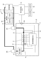
本実施形態の電力管理システム10は、4輪の自動車などの車両に搭載される車両の電力管理システム10であって、図1に示すように、バッテリ装置20と、車両のエンジンに取り付けられる車両発電機50と、バッテリ装置20に接続されると共に、車両発電機50に接続される車両負荷60と、車両負荷60および車両発電機50に接続される電子制御装置(以下、ECU)70と、車両の走行状態を監視する車両監視部80と、警告表示を行う警告表示部90とを備えて構成されている。
<Embodiment 1>
Embodiment 1 will be described with reference to FIGS. 1 to 5.
The
車両発電機50は、例えば、オルターネータなどであって、車両の図示しないエンジンに取り付けられ、エンジンの駆動に伴って回転することで発電する。また、車両発電機50は、車両負荷60およびバッテリ装置20に接続されており、車両負荷60やバッテリ装置20などに電力供給を行う。また、車両発電機50は、エンジンの回転数を上げて回転数を上げる、もしくは、図示しないフィールドコイルのフィールド電流を増加させて発電電圧を高くすることで発電量を増加させることができるようになっている。
The
車両負荷60は、バッテリ装置20もしくは車両発電機50からの電力供給により、稼働する。また、車両負荷60は、車両の走行や車両の安全性に関連する重要負荷61と、車両走行や安全性に関連しない一般負荷62とに分類される。重要負荷61において車両の走行に関する負荷としては、例えば、エンジン始動装置、燃料ポンプ制御装置、アクセル制御装置、ブレーキ制御装置などであって、車両の安全性に関する負荷としては、例えば、パワーステアリング、ABS(アンチロックブレーキシステム)、TCS(トラクションコントロールシステム)、エアバッグ、ヘッドライト、ウインカーなどである。また、一般負荷62としては、例えば、パワースライドドアやパワーウィンドウなどドアの開閉やパワーシートなどの移動を補助するアシスト制御装置、室温を調整する空調装置、オーディオ装置など、快適性を向上させる負荷である。
The
ECU70は、エンジン、車両負荷60、車両発電機50などと通信線によって接続されており、エンジンの回転数などエンジンを制御するエンジン制御処理や、後述する電力制御処理(「電力制御工程」の一例)を行う。
The
車両監視部80は、ECU70と通信線で接続されている。また、車両監視部80は、例えば、車両に設けられたナビゲーションシステムと連動することで車両が一般道路と高速道路のいずれの道路を走行しているか監視しており、その監視結果は通信線を通じてECU70に入力される。そして、ECU70は、監視結果に基づいて、車両の走行状態が一般走行か高速走行か判断し、車両の走行状態をバッテリ装置20に入力する。
The vehicle monitoring unit 80 is connected to the
警告表示部90は、車両のダッシュボードに組み付けられた図示しないインスツルメントパネルに設けられており、ECU70と信号線もしくは通信線によって接続されている。警告表示部90は、ECU70からの表示指示に応答し、警告表示部90を作動させることで運転手や作業者などの使用者に対して警告を促すことができるようになっている。
The
バッテリ装置20は、車両負荷60に電力供給するものであって、二次電池21と、電流センサ22と、温度センサ23と、電圧センサ24と、電流遮断部25と、電池管理装置(以下、「BMU」)30とを備えて構成されている。
The
二次電池21は、複数(本実施形態では4つ)のリチウムイオン電池を直列に接続して構成されており、この二次電池21は、負極側がバッテリケースCに設けられた負極端子20Aに接続され、正極側がバッテリケースCに設けられた正極端子20Bに接続されている。
The
電流センサ22は、二次電池21と負極端子20Aとの間の電力線PLに接続されており、電力線PLに流れる電流を検出し、その検出電流に応じた電流値を出力する。
温度センサ23は、接触式あるいは非接触式とされており、二次電池21の温度を測定し、その測定温度に応じた温度測定値を出力する。
The
電圧センサ24は、二次電池21の両端子部に接続されており、二次電池21の端子間電圧を検出し、その検出電圧に応じた電圧値を出力する。
電流センサ22、温度センサ23、電圧センサ24は、信号線もしくは通信線を介してBMU30に接続されており、それぞれのセンサからの出力は、BMU30に取り込まれるようになっている。
The
The
電流遮断部25は、例えば、FET等の半導体スイッチやリレーであり、二次電池21と正極端子20Bとの間の電力線PL上に設けられている。電流遮断部25は、BMU30からの駆動指令に応答して作動し、二次電池21と正極端子20Bとの間の電力線PLの電流を遮断する。
The current interrupting
BMU30は、電流遮断部25およびバッテリケースCに設けられた通信コネクタ20Cに信号線もしくは通信線によって接続されている。また、BMU30は、二次電池21に接続されることで二次電池21から直接電力の供給を受けている。また、BMU30は、図2に示すように、中央処理装置(以下、「CPU」)31と、通信部32と、電流遮断部駆動部33と、電池監視部34と、記憶部35とを備えて構成されている。
The
通信コネクタ20Cは、図1に示すように、車両のECU70に設けられた車両側通信コネクタ71と接続可能とされており、通信コネクタ20Cと車両側通信コネクタ71とが接続されることでBMU30とECU70とは通信可能状態となる。
As shown in FIG. 1, the
通信部32は、図2に示すように、一端がCPU31に接続されると共に、他端が通信コネクタ20Cに接続されており、CPU31とECU70との間の信号もしくはデータの送受信を行う。
電流遮断部駆動部33は、CPU31からの遮断指令もしくは解除指令を受信し、指令に応じた駆動指令を電流遮断部25へ出力する。
As shown in FIG. 2, the
The current interrupting
電池監視部34は、BMU30に取り込まれた各センサ22,23,24からの出力を取り込むことにより二次電池21の状態をモニタリングして二次電池21の異常状態を検出し、その検出結果をCPU31に出力する。
記憶部35は、BMU30の動作を制御する為の各種のプログラムが記憶されている。
The
The
CPU31は、受信した各種の信号やデータと、記憶部35から読み出したプログラムとに基づいて、図3および図5に示すECU70に対する事前予告処理(「予告工程」の一例)や電流遮断処理、取消処理など、各部の監視および制御を行う。
Based on the received various signals and data, and the program read from the
次に、BMU30による事前予告処理および電流遮断処理について説明し、続けて、ECU70における電力制御処理について説明する。
まず、電流遮断処理について簡単に説明する。
BMU30のCPU31は、電池監視部34の検出結果から二次電池21が、例えば、過充電状態、過放電状態、過度な温度上昇など、異常状態になる虞があるか判断する。CPU31は、二次電池21が異常状態になる虞があると判断した場合には、電流遮断部駆動部33を通して遮断指令を電流遮断部25に入力し、二次電池21の電流を遮断する。これにより、二次電池21が過充電状態、過放電状態、過度な温度上昇による劣化状態に至ることを防ぎ、二次電池21を保護することができる。
Next, the advance notice process and current interruption process by the
First, the current interruption process will be briefly described.
The
ところで、電流遮断処理により、電流遮断部25において電流を遮断した場合、二次電池21を保護することができるものの、車両負荷60への電力供給は、車両発電機50によってのみ行われることになる。したがって、車両負荷60の消費電量が車両発電機50の発電量を超えると、発電電圧が低下してしまい、車両走行や安全性に関係する重要負荷61の動作が不安定になってしまう虞がある。そこで、本実施形態のBMU30は、二次電池21の異常状態を検出後、電流遮断部25において電流を遮断する前に、事前予告処理を行う。
By the way, when current is interrupted by the current interrupting
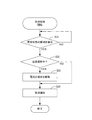
以下に、事前予告処理および電流遮断処理について、図3を参照しつつ説明する。
CPU31は、電池監視部34の検出結果に基づいて、二次電池21の状態を監視しており、二次電池21において、例えば、過充電状態、過放電状態、過度な温度上昇など、異常が生じた場合、電池監視部34の検出結果から二次電池21が異常状態であると判断する(S11)。CPU31において二次電池21が異常状態であると判断された場合、CPU31は、電流遮断の時期を決定(S12)し、ECU70に電流遮断の時期を事前予告する(S13)。
Hereinafter, the advance notice process and the current interruption process will be described with reference to FIG.
The
そして、CPU31は、電流遮断の時間になったところで、電流遮断部25において電流を遮断する(S14)。
具体的には、CPU31は、電池監視部34の検出結果から二次電池21が異常状態であることを検出すると、例えば、電流を遮断するまでの時間を1分と決定する。
And CPU31 interrupts | blocks an electric current in the electric
Specifically, when the
次に、CPU31は、電流遮断の時間が決定したところで、通信部32を通じて、電流遮断が1分後であることを事前予告としてECU70に入力する。そして、CPU31は、事前予告から1分経過したところで、電流遮断部駆動部33を通じて電流遮断部25に遮断指令を入力し、電流遮断部25において電流を遮断する。
Next, when the current interruption time is determined, the
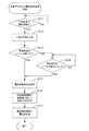
次に、事前予告が入力されたECU70の電力制御処理について、図4を参照しつつ説明する。電力制御処理は、車両発電機50から車両負荷60への電力供給の制御を行う。
具体的には、ECU70は、バッテリ装置20におけるBMU30からの事前予告の入力を監視している(S21)。そして、ECU70は、BMU30のCPU31からの事前予告が入力されたことを検出すると、事前予告のあった時間内に以下の制御を行う。
Next, the power control process of the
Specifically, the
ECU70は、まず、はじめに、エンジンのアイドリングを一時的に停止するアイドリングストップ禁止制御を行い(S22)、エンジンが一時的に停止して車両発電機50から車両負荷60に対して電力供給がなくなることを防ぐ。
First, the
次に、車両発電機50が発電している発電量と、車両負荷60が消費している消費電量とを比較し(S23)、消費電量が発電量よりも大きい場合、ECU70は、車両発電機50にフィールド電流の増加指令を入力し、車両発電機50の発電量を増加させる発電量の増加制御を行う(S24)。
ところで、CPU31がECU70に対して事前予告を入力した後に、二次電池21の異常状態が解消された場合には、バッテリ装置20における二次電池21の電流の遮断を解除すると共に、電力制御処理をキャンセルし、電力管理システム10を通常の状態に戻す必要がある。そこで、電力管理システム10は、CPU31において取消処理を行い、続けて、ECU70に対して取消通知を行う。
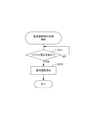
以下に、CPU31における取消処理について、図5を参照しつつ説明する。
CPU31は、事前予告処理を実施した後も、電池監視部34を通して二次電池21の監視を継続しており、二次電池21において異常状態が改善した場合には、電池監視部34の検出結果から二次電池21の異常状態が解消されていることを検出する(S31)。
Next, the power generation amount generated by the
By the way, when the abnormal state of the
Below, the cancellation process in CPU31 is demonstrated, referring FIG.
The
そして、CPU31は、電池監視部34の検出結果から二次電池21の異常状態が解消されていることを検出した場合、電流遮断部25において電流遮断がされているか検出する(S32)。CPU31は、電流遮断部25において電流が遮断中であることを検出した場合、電流遮断部駆動部33を通じて電流の遮断を解除する(S33)。
そして、CPU31は、バッテリ装置20の二次電池21から車両負荷60に電力が供給できる状態になったところで、ECU70に取消通知を入力する(S34)。
したがって、図4に示すように、ECU70において、車両発電機50が発電している発電量と、車両負荷60が消費している消費電量とを比較し(S23)、消費電量が発電量よりも大きくない場合には、ECU70は、BMU30からの取消通知の入力を監視し(S23−1)、取消通知の入力がない場合には、所定の時間間隔で、車両負荷60の消費電量が車両発電機50の発電量よりも大きくならないか繰り返しチェックする(S23)。そして、BMU30のCPU31からの取消通知が入力されたことを検出すると、アイドリングストップ禁止制御を解除する(S23−2)。
Then, when the
Then, the
Therefore, as shown in FIG. 4, the
そして、車両負荷60の消費電量が車両発電機50の発電量よりも大きく、車両発電機50においてフィールド電流の増加により発電量を増加させた場合(S24)には、再度、車両発電機50が発電している発電量と、車両負荷60が消費している消費電量を比較する(S25)。消費電量が発電量よりも大きくない場合、ECU70は、BMU30からの取消通知の入力を監視し(S25−1)、取消通知の入力がない場合には、所定の時間間隔で、車両負荷60の消費電量と車両発電機50の発電量との比較を繰り返し行う(S25)。そして、BMU30のCPU31からの取消通知が入力されたことを検出すると、アイドリングストップ禁止制御を解除する(S25−2)。また車両発電機50における発電量の増加制御を解除することで(S25−3)、車両発電機50を通常の状態に復帰させる。
一方、消費電量が発電量よりも大きい場合には、ECU70は、車両発電機50にエンジンの駆動回転数を上げて車両発電機50の回転数を上げる指令を入力し、車両発電機50の発電量をさらに増加させる(S26)。
When the power consumption of the
On the other hand, when the power consumption is larger than the power generation, the
そして、車両発電機50において発電量を増加させたところで、再度、車両発電機50が発電している発電量と、車両負荷60が消費している消費電量を比較し(S27)、消費電量が発電量よりも大きくない場合、ECU70は、BMU30からの取消通知の入力を監視し(S27−1)、取消通知の入力がない場合には、所定の時間間隔で、車両負荷60の消費電量と車両発電機50の発電量との比較を繰り返し行う(S27)。そして、BMU30のCPU31からの取消通知が入力されたことを検出すると、アイドリングストップ禁止制御の解除(S27−2)および車両発電機50における発電量の増加制御を解除する(S27−3)。
Then, when the power generation amount is increased in the
一方、消費電量が発電量よりも大きい場合、ECU70は、車両負荷60のうち、車両の走行や安全性に関係のない一般負荷62への電力供給の低減もしくは停止を実施し(S28)、消費電量が発電量よりも大きくならないように、車両発電機50から車両負荷60への電力供給の制御を行う。そして、ECU70は、BMU30からの取消通知の入力を監視し(S28−1)、BMU30のCPU31からの取消通知が入力されたことを検出すると、アイドリングストップ禁止制御の解除(S28−2)および車両発電機50における発電量の増加制御を解除する(S28−3)。また、一般負荷62の電力供給の制限を解除し(S28−4)、全ての車両負荷60を復帰させる。
On the other hand, when the power consumption is larger than the power generation, the
つまり、バッテリ装置20のBMU30は、電流遮断部25において電流を遮断する前に、ECU70に対して事前予告を行うことで、二次電池21から車両負荷60への電力供給がなくなる前に、電力制御をする時間をECU70に与えることができる。
That is, the
そして、ECU70は、BMU30からの事前通知が入力され、バッテリ装置20の電流が遮断される前に、車両発電機50の発電量を増加させたり、車両負荷60の一般負荷62の消費電量を低減させたりすることで、バッテリ装置20において電流が遮断された後も、車両負荷60の重要負荷61の動作が、電圧低下によって不安定になることを防ぐことができる。
The
また、ECU70において重要負荷61の動作が不安定になることを防ぐ対策が整った後、バッテリ装置20において電流を遮断して、二次電池21を、車両負荷60や車両発電機50から切り離すことができるから、二次電池21が使用できなくなる前に、保護することができる。
Further, after measures are taken to prevent the operation of the
本実施形態は、以上のような構成であって、続いて、電力管理システム10の作用および効果について説明する。
The present embodiment is configured as described above. Next, the operation and effect of the
本実施形態では、バッテリ装置20のBMU30が、二次電池21の異常状態を検出すると、電流遮断部25において電流を遮断する所定の時間前に、ECU70に事前通知を入力する。そして、事前通知が入力されたECU70は、バッテリ装置20の電流遮断部25において電流が遮断されるまでの間に、車両発電機50から車両負荷60に供給される電力を制御し、バッテリ装置20からの電力供給がなくなった場合でも、車両負荷60の重要負荷61の動作が電圧低下によって不安定になることを防ぐことができる。
In the present embodiment, when the
また、バッテリ装置20の二次電池21に関しても、所定の時間経過後に、電流遮断部25において電流が遮断されて、車両負荷60や車両発電機50と切り離された状態になるから、二次電池21の異常状態が悪化して使用できなくなることを防ぐことができる。
Also, with respect to the
また、本実施形態のバッテリ装置20の二次電池21は、リチウムイオン電池からなっており、リチウムイオン電池は、電池の特性から、一般に、電池の電流値や電圧値などの状態を監視するBMU30を有している。したがって、本実施形態によると、BMU30を利用して、ECU70に対して事前予告をするから、例えば、事前予告を行う制御部を別途設けることなく、ECU70に対して事前通知を行うことができる。これにより、電力管理システム10を簡素化すると共に、製造コストが高くなることを防ぐことができる。
In addition, the
また、一般に、4輪自動車用のバッテリ装置は、2輪車用のバッテリ装置とは異なり、エンジンの始動や駆動部材の制御だけでなく、車両内の電装品に対して電力供給する構成となっているため、車両負荷における一般負荷の電力消費量が高い傾向にある。したがって、バッテリ装置から車両負荷への電力供給がなくなると、車両負荷全体の電圧が低下することで、車両負荷の動作が不安定になってしまう。
ところが、本実施形態の電力管理システム10は、4輪自動車のバッテリ装置を使用しているものの、バッテリ装置20において電流が遮断される前に、ECU70に対して事前予告を入力し、ECU70において電力制御することができるから、車両負荷60の動作が不安定になることを防ぐ上で、非常に有効である。
In general, a battery device for a four-wheeled vehicle is different from a battery device for a two-wheeled vehicle in that not only the engine is started and the drive member is controlled, but also power is supplied to electrical components in the vehicle. Therefore, the power consumption of the general load in the vehicle load tends to be high. Therefore, when the power supply from the battery device to the vehicle load is lost, the voltage of the entire vehicle load decreases, and the operation of the vehicle load becomes unstable.
However, although the
<実施形態2>
次に、実施形態2について図6および図7を参照して説明する。
実施形態2は、実施形態1における事前予告処理および電力制御処理の内容を変更したものであって、実施形態1と共通する構成、作用、および効果については重複するため、その説明を省略する。また、実施形態1と同じ構成については同一の符号を用いるものとする。
<Embodiment 2>
Next, Embodiment 2 will be described with reference to FIGS.
In the second embodiment, the contents of the advance notice process and the power control process in the first embodiment are changed, and the configurations, operations, and effects common to the first embodiment are duplicated, and thus the description thereof is omitted. The same reference numerals are used for the same configurations as those in the first embodiment.
まず、実施形態2における事前予告処理について、図6を参照しつつ、説明する。実施形態2の事前予告処理は、図6に示すように、異常状態のレベルに合わせて複数回に亘って事前処理を行うものであって、二次電池21の異常状態を検出した後からの処理が実施形態1と異なっている。
First, the prior notice process in the second embodiment will be described with reference to FIG. As shown in FIG. 6, the prior notice process of the second embodiment is performed in advance for a plurality of times in accordance with the level of the abnormal state, and after the abnormal state of the
具体的には、CPU31は、電池監視部34の検出結果から、二次電池21が例えば、過充電状態、過放電状態、過度な温度上昇など、異常状態に至る虞があるか判断する(S111)。異常状態が検出されない場合、CPU31において二次電池21の監視を継続する。また、CPU31において、二次電池21の異常状態が検出された場合には、CPU31から通信部32を通じて1回目の事前予告をECU70に入力する(S112)。
Specifically, the
次に、CPU31は、電池監視部34の検出結果から、異常状態のレベルを判断する(S113)。CPU31において、異常状態のレベルが高くないと判断した場合には、CPU31において、異常状態のレベルが高くなるまで、二次電池21の監視を継続する(S114)。
Next, the
一方、CPU31において、異常状態のレベルが高く緊急性を要すると判断した場合は、電流遮断の時期を決定する(S115)。具体的には、CPU31が電池監視部34の検出結果から、電流を遮断しなければならないと判断した場合、例えば、電流を遮断するまでの時間を10分と決定する。
On the other hand, if the
次に、CPU31は、電流遮断までの時間を基準に所定の時間間隔で複数回に亘ってECU70に対して事前予告を行う(S116)。具体的には、例えば、CPU31は、ECU70に対して、2回目の事前予告を速やかに行い、次に、電流遮断の5分前、1分前と合計4回に亘って事前予告を行う。
そして、CPU31は、電流遮断の時間になったところで、電流遮断部駆動部33を通じて遮断指令を電流遮断部25へ入力し、電流遮断部25において電流を遮断する(S117)。
Next, the
Then, when it is time to cut off the current, the
次に、実施形態2における電力制御処理について、図7を参照しつつ説明する。実施形態2の電力制御処理は、複数回に亘って入力される事前予告に応じて車両発電機50および車両負荷60の制御を行うものであって、ECU70においてアイドリングストップ禁止制御をした後の処理からが実施形態1と異なっている。
Next, power control processing in the second embodiment will be described with reference to FIG. The power control process according to the second embodiment controls the
ECU70は、バッテリ装置20におけるBMU30からの事前予告の入力を監視しており(S121)、ECU70は、バッテリ装置20のCPU31から1回目の事前予告が入力されると、まず、警告表示部90において1回目の警告を表示(S122)し、アイドリングストップ禁止制御を行う(S123)。そして、BMU30からの2回目の事前予告の入力を監視する(S124)。
The
そして、ECU70に対して、BMU30から2回目の事前予告が入力されると、警告表示部90において2回目の警告を表示(S125)し、車両発電機50が発電している発電量と、車両負荷60が消費している消費電量とを比較する(S126)。消費電量が発電量よりも大きくない場合、ECU70は、BMU30からの取消通知の入力を監視し(S126−1)、取消通知の入力がない場合には、所定の時間間隔で、車両負荷60の消費電量が車両発電機50の発電量よりも大きくならないか繰り返しチェックする(S126)。そして、BMU30のCPU31からの取消通知が入力されたことを検出すると、アイドリングストップ禁止制御を解除する(S126−2)。
一方、消費電量が発電量よりも大きい場合には、ECU70は、車両発電機50にフィールド電流の増加指令を入力し、車両発電機50の発電量を増加させる(S127)。そして、BMU30からの3回目の事前予告の入力を監視する(S128)。
When the second advance notice is input from the
On the other hand, when the power consumption is greater than the power generation, the
次に、ECU70に対して、BMU30から3回目の事前予告が入力されると、警告表示部90において3回目の警告を表示(S129)し、車両発電機50が発電している発電量と、車両負荷60が消費している消費電量とを比較する(S130)。ECU70は、BMU30からの取消通知の入力を監視し(S130−1)、取消通知の入力がない場合には、所定の時間間隔で、車両負荷60の消費電量と車両発電機50の発電量との比較を繰り返し行う(S130)。そして、BMU30のCPU31からの取消通知が入力されたことを検出すると、アイドリングストップ禁止制御を解除する(S130−2)。また車両発電機50における発電量の増加制御を解除することで(S130−3)、車両発電機50を通常の状態に復帰させる。
一方、消費電量が発電量よりも大きい場合には、ECU70は、エンジンの駆動回転数を上げて車両発電機50の回転数を上げ、車両発電機50の発電量をさらに増加させる(S131)。そして、4回目の事前予告の入力を監視する(S132)。
Next, when the third advance notice is input from the
On the other hand, when the power consumption is larger than the power generation amount, the
そして、最終的に、ECU70に対して、BMU30から4回目の事前予告が入力されることになると、警告表示部90において最終警告を表示(S133)し、再び、車両発電機50が発電している発電量と、車両負荷60が消費している消費電量を比較する(S134)。消費電量が発電量よりも大きくない場合、ECU70は、BMU30からの取消通知の入力を監視し(S134−1)、取消通知の入力がない場合には、所定の時間間隔で、車両負荷60の消費電量と車両発電機50の発電量との比較を繰り返し行う(S134)。そして、BMU30のCPU31からの取消通知が入力されたことを検出すると、アイドリングストップ禁止制御の解除(S134−2)および車両発電機50における発電量の増加制御を解除する(S134−3)。
Finally, when the fourth advance notice is input from the
一方、消費電量が発電量よりも大きい場合、ECU70は、車両負荷60の一般負荷62への電力供給の低減もしくは停止を実施する(S135)。そして、ECU70は、BMU30からの取消通知の入力を監視し(S135−1)、BMU30のCPU31からの取消通知が入力されたことを検出すると、アイドリングストップ禁止制御の解除(S135−2)および車両発電機50における発電量の増加制御を解除する(S135−3)。また、一般負荷62の電力供給の制限を解除し(S135−4)、全ての車両負荷60を復帰させる。
On the other hand, when the power consumption is larger than the power generation, the
つまり、本実施形態によると、異常状態が検出された段階でまず1回目の事前予告を行い、異常状態のレベルが高くなった際に、再度事前予告を行うなど、異常状態が検出されたときと、異常状態のレベルが高くなったときに、ECU70に対して事前予告するから、ECU70において電力制御を異常状態のレベル(事前予告の回数)に合わせて、電力制御を段階的に行うことができる。
In other words, according to the present embodiment, when an abnormal state is detected, for example, when the abnormal state is detected, the first advance notice is given first, and the advance notice is given again when the level of the abnormal state becomes high. Since the
また、ECU70は、BMU30から段階的に複数回に亘って入力された事前予告により、電力制御の準備を段階的に進めることで、車両側に負担が集中することを防ぐことができる。また、ECU70において、電力制御の準備を段階的に進めているから、例えば、車両発電機による発電量の増加や一般負荷の電力供給の制限など一度に全ての電力制御を行う場合に比べて、電力制御の無駄を低減させることができる。
Moreover, ECU70 can prevent that a burden concentrates on the vehicle side by advancing the preparation of electric power control stepwise by the prior notice input several times stepwise from BMU30. In addition, in the
また、二次電池21の異常状態が解消された際にも、電力制御を行った部分のみを復帰させるだけで済むから、電力管理システム10を通常の状態に速やかに復帰させることができる。さらに、BMU30からECU70に対して事前予告が入力される毎に、使用者に対して警告表示部90において警告が表示されるから、車両が停車可能な場合には、使用者は車両を停車し、バッテリ装置20を保護することができる。
Further, even when the abnormal state of the
<実施形態3>
次に、実施形態3について図8を参照して説明する。
実施形態3は、実施形態1における事前予告処理および電力制御処理の内容を変更したものであって、実施形態1と共通する構成、作用、および効果については重複するため、その説明を省略する。また、実施形態1と同じ構成については同一の符号を用いるものとする。また、実施形態3の電力制御処理については、実施形態2の電力制御処理と同じ構成であるため、その説明を省略する。
<Embodiment 3>
Next, Embodiment 3 will be described with reference to FIG.
In the third embodiment, the contents of the advance notice process and the power control process in the first embodiment are changed, and the configurations, operations, and effects common to the first embodiment are duplicated, and thus the description thereof is omitted. The same reference numerals are used for the same configurations as those in the first embodiment. In addition, the power control process of the third embodiment has the same configuration as the power control process of the second embodiment, and a description thereof will be omitted.
実施形態3の事前予告処理は、図8に示すように、車両の走行状態に合わせて事前予告の開始時期を変更するものであって、電流を遮断する時期を決定した後からの処理が実施形態1と異なっている。 As shown in FIG. 8, the advance notice process of the third embodiment changes the start time of the advance notice according to the running state of the vehicle, and the process is performed after determining the time to cut off the current. Different from Form 1.
具体的には、CPU31は、電池監視部34の検出結果から、二次電池21が、例えば、過充電状態、過放電状態、過度な温度上昇など、異常状態に至る虞があるか判断する(S211)。異常状態が検出されない場合、CPU31において二次電池21の監視を継続する。また、CPU31において、二次電池21の異常状態が検出された場合、CPU31は、電流遮断の時期を決定(S212)する。具体的には、電流遮断の時期を異常状態が検出されてから30分後に決定する。
Specifically, the
次に、CPU31は、予め車両のECU70から入力された車両の走行状態に基づいて事前予告の時期を判断する(S213)。CPU31の判断の結果、走行状態が高速走行の場合、事前予告開始時期を早期に設定(S214)し、走行状態が一般走行の場合、事前予告開始時期を通常に設定する(S215)。
Next, the
具体的には、例えば、車両が高速道路を走行している場合、速やかに車両を停車することができない虞があるため、CPU31は、例えば、事前予告の開始時期を、直ちに開始するように設定し、早期の所定時間間隔で複数回に亘ってECU70に対して事前予告を行う(S216)。具体的には、例えば、CPU31は、ECU70に対して、2回目の事前予告を速やかに行い、次に、電流遮断の20分前、10分前と複数回に亘って事前予告を行う。
Specifically, for example, when the vehicle is traveling on an expressway, there is a possibility that the vehicle cannot be quickly stopped. Therefore, for example, the
一方、車両が一般道路を走行している場合、車両を速やかに停車することが可能と考えられるため、事前予告の開始時期を電流遮断開始の10分前に設定する。そして、CPU31は、電流遮断までの時間を通常の所定時間間隔で複数回に亘ってECU70に対して事前予告を行う(S217)。
On the other hand, when the vehicle is traveling on a general road, it is considered possible to stop the vehicle promptly, so the start time of the advance notice is set 10 minutes before the start of current interruption. Then, the
そして、CPU31は、電流遮断の時間になったところで、電流遮断部駆動部33を通じて遮断指令を電流遮断部25へ入力し、電流遮断部25において電流を遮断する(S218)。
すなわち、本実施形態によると、車両の走行状態によっては車両を急に停止させることができない場合には、使用者が余裕をもって対処できるように、早めに警告することができると共に、ECU70においても余裕をもって電力制御することができる。
Then, when it is time to cut off the current, the
That is, according to the present embodiment, when the vehicle cannot be stopped suddenly depending on the traveling state of the vehicle, a warning can be given early so that the user can deal with it with a margin. Can control the power.
<他の実施形態>
本明細書で開示される技術は上記記述及び図面によって説明した実施形態に限定されるものではなく、例えば次のような種々の態様も含まれる。
(1)上記実施形態では、電流センサ22、温度センサ23、電圧センサ24からの出力に基づいてBMU30が二次電池21の異常状態を検出する構成にした。しかしながら、これに限らず、各種センサを設けることで、BMUにおいて、二次電池内で発生するガスや二次電池の膨張などを種々の異常状態を検出できるように構成してもよい。
<Other embodiments>
The technology disclosed in the present specification is not limited to the embodiments described with reference to the above description and drawings, and includes, for example, the following various aspects.
(1) In the above embodiment, the
(2)上記実施形態では、車内に警告表示部90を設けて、使用者に対して警告を表示する構成とした。しかしながら、これに限らず、音声や警告音、警告灯などによって使用者に警告する構成にしてもよい。
(3)上記実施形態では、電流遮断部25を、半導体スイッチやリレーによって構成した。しかしながら、これに限らず、過電流によって溶断されるヒューズや、過電流および強制的に溶断可能なSCプロテクター(Self Control Protector)などの保護素子などによって構成してもよい。
(2) In the above embodiment, the
(3) In the said embodiment, the electric
(4)上記実施形態では、バッテリ装置20のBMU30が、事前予告を行い、電流遮断部25において電流を遮断するよりも前に、ECU70が電力制御する構成とした。しかしながら、これに限らず、電流が遮断されたことを検出することで、電力制御を速やかに行い、重要な負荷の動作が不安定になることを防ぎつつ、二次電池を保護する構成にしてもよい。
(4) In the above embodiment, the
以下に、電流が遮断されたことを検出する電流遮断検出処理について詳細に説明する。なお、以下に示す実施形態のバッテリ装置の構成については、実施形態1と共通する構成であるため、その説明を省略する。また、ECU70において行われる電力制御処理については、実施形態1における「事前予告」を「電流遮断通知」に読み替えるものとする。
Hereinafter, a current interruption detection process for detecting that an electric current has been interrupted will be described in detail. In addition, about the structure of the battery apparatus of embodiment shown below, since it is a structure which is common in Embodiment 1, the description is abbreviate | omitted. In addition, regarding the power control processing performed in the
まず、電流遮断検出処理を説明する前に、電流の遮断を検出する手段について説明する。
一般に、オルターネータなどの車両発電機は、エンジンの駆動回転と連動して回転し、発電する。このため、回転を利用して発電した電流は交流であり、車両発電機は、交流を直流変換させて電力供給を行う。
First, means for detecting current interruption will be described before explaining the current interruption detection processing.
In general, a vehicle generator such as an alternator rotates in conjunction with engine drive rotation to generate electric power. For this reason, the electric current generated using the rotation is alternating current, and the vehicle generator performs power supply by converting the alternating current into direct current.
したがって、車両発電機から供給される電力は、交流から直流に変換したとしても、脈動のような定期的な電圧変動、いわゆるリップル電圧が発生する。 Therefore, even if the electric power supplied from the vehicle generator is converted from alternating current to direct current, periodic voltage fluctuation such as pulsation, so-called ripple voltage, is generated.
ところが、このリップル電圧は、車両発電機が接続された電源回路にバッテリ装置が接続されていると、バッテリ装置がリップル電圧を吸収し、バッテリ装置において電流が遮断されると、リップル電圧が吸収されず、電圧変動が顕著化することを特定した。
そこで、以下の実施形態では、電圧センサ24によって、電源回路のおける電圧変動を検出することで、電流遮断部25での電流の遮断が検出できることを特定し、この検出結果に基づいて、電力制御を行うこととした。
However, the ripple voltage is absorbed by the battery device when the battery device is connected to the power circuit to which the vehicle generator is connected, and is absorbed when the current is interrupted in the battery device. First, it was specified that voltage fluctuations become prominent.
Therefore, in the following embodiment, it is specified that the current interruption in the
次に、電流遮断検出処理について図9を参照して、説明する。
電流遮断検出処理では、電圧センサ24から電池監視部34に入力された電圧値にもとにその結果をCPU31が監視している(S311)。そして、電圧センサ24においてリップル電圧が検出された場合には、CPU31は、電源遮断部において電流が遮断されたと判断し、ECU70に対して電流遮断通知を行う(S312)。
Next, the current interruption detection process will be described with reference to FIG.
In the current interruption detection process, the
以上のように、電流が遮断されたことを検出する電流遮断検出処理によって電流が遮断されたことを検出することで、電力制御を速やかに行い、重要負荷61の動作が不安定になることを防ぎつつ、二次電池21を保護することができる。
As described above, by detecting that the current has been cut off by the current cut-off detection process for detecting that the current has been cut off, the power control is performed quickly, and the operation of the
また、例えば、電流遮断部25において故障が発生したり、電力線PLが断線したりするなど、意図せずに、二次電池21の電流が遮断された場合においても、CPU31からECU70に対して電流遮断通知を行うことで、重要負荷61の動作が不安定になることを防ぐことができる。
Further, even when the current of the
(5)上記実施形態では、二次電池21を、リチウムイオン電池を直列に接続して構成した。しかしながら、これに限らず、電池管理装置が設けられた電池(例えば、鉛蓄電池、ニッケル・カドミウム蓄電池、ニッケル・水素蓄電池など)を用いてもよい。
(5) In the above embodiment, the
10:電力管理システム
21:二次電池
25:電流遮断部
30:電池管理装置(「制御部」の一例)
31:中央処理装置(「制御部」の一例)
34:電池監視部(「検出部」の一例)
50:車両発電機(「発電機」の一例)
60:車両負荷(「負荷」の一例)
61:重要負荷(「負荷」の一例)
62:一般負荷(「負荷」の一例)
70:電子制御装置(「電力制御部」の一例)
80:車両監視部
90:警告表示部(「警告発信部」の一例)
10: Power management system 21: Secondary battery 25: Current cut-off unit 30: Battery management device (an example of “control unit”)
31: Central processing unit (an example of “control unit”)
34: Battery monitoring unit (an example of “detection unit”)
50: Vehicle generator (an example of “generator”)
60: Vehicle load (an example of “load”)
61: Important load (an example of “load”)
62: General load (an example of “load”)
70: Electronic control device (an example of “power control unit”)
80: Vehicle monitoring unit 90: Warning display unit (an example of “warning transmission unit”)
Claims (15)
前記二次電池に接続される発電機と、
前記二次電池に接続されると共に前記発電機に接続され、前記二次電池および前記発電機の電力供給により稼働する負荷と、
前記発電機から前記負荷への電力供給を制御する電力制御部と、
前記二次電池の異常状態を検出する検出部と、
前記二次電池と前記負荷との間の電流を遮断する電流遮断部と、
前記検出部において異常状態が検出された後、前記電流遮断部において電流を遮断する前に前記電力制御部に対して前記電流を遮断することを事前予告する制御部と、を備え、
前記電力制御部は、前記事前予告に基づいて前記発電機から前記負荷への電力供給を制御する電力管理システム。 A secondary battery,
A generator connected to the secondary battery;
A load connected to the secondary battery and connected to the generator, and operated by supplying power from the secondary battery and the generator;
A power control unit for controlling power supply from the generator to the load;
A detection unit for detecting an abnormal state of the secondary battery;
A current interrupting unit that interrupts a current between the secondary battery and the load;
A control unit for pre-notifying the power control unit to cut off the current before an abnormal state is detected in the detection unit and before cutting off the current in the current cut-off unit;
The power control unit is a power management system that controls power supply from the generator to the load based on the advance notice.
前記電力制御部は、前記取消通知により、前記事前予告に基づいて行った前記電力供給の制御をキャンセルする請求項1から請求項4のいずれか一項に記載の電力管理システム。 When the controller detects that the abnormal state has been resolved after the advance notice, the controller notifies the power controller to cancel the interruption of the current. And
The power management system according to any one of claims 1 to 4, wherein the power control unit cancels the control of the power supply performed based on the advance notice in response to the cancellation notification.
前記車両の走行状態を監視する車両監視部を備え、
前記制御部は、前記車両監視部において検出された前記車両の走行状態に応じて前記電流の遮断の時期と前記事前予告の時期との間の時間間隔を決定する電力管理システム。 The power management system according to any one of claims 1 to 5 is a power management system mounted on a vehicle,
A vehicle monitoring unit for monitoring the running state of the vehicle;
The said control part is an electric power management system which determines the time interval between the time of interruption | blocking of the said electric current, and the time of the prior notice according to the driving state of the said vehicle detected in the said vehicle monitoring part.
前記電力制御部は、前記車両に設けられた電子制御装置であり、
前記車両内には、警告を行う警告発信部が設けられており、
前記電子制御装置は、前記制御部からの前記事前予告により前記警告発信部において警告を行う電力管理システム。 The power management system according to any one of claims 1 to 6 is a power management system mounted on a vehicle,
The power control unit is an electronic control device provided in the vehicle,
In the vehicle, there is provided a warning transmitter for warning,
The electronic control device is a power management system in which a warning is issued in the warning transmission unit by the advance notice from the control unit.
前記電力制御部は、前記車両に設けられた電子制御装置であり、
前記発電機は、前記車両のエンジンの駆動に伴って稼働する車両発電機であり、
前記電子制御装置は、前記事前予告があった場合には、前記エンジンのアイドリングを一時的に停止するアイドリングストップを禁止する電力管理システム。 The power management system according to any one of claims 1 to 7 is a power management system mounted on a vehicle,
The power control unit is an electronic control device provided in the vehicle,
The generator is a vehicle generator that operates in conjunction with the driving of the engine of the vehicle,
The electronic control device is a power management system for prohibiting idling stop that temporarily stops idling of the engine when the advance notice is given.
前記発電機は、前記車両のエンジンの駆動に伴って稼働する車両発電機であり、
前記電力制御部は、前記事前予告があった場合には、前記車両発電機のフィールド電流を増加させる、もしくはエンジンの駆動回転数を上げることで前記車両発電機の発電量を増加させる電力管理システム。 The power management system according to any one of claims 1 to 8 is a power management system mounted on a vehicle,
The generator is a vehicle generator that operates in conjunction with the driving of the engine of the vehicle,
The power control unit increases the power generation amount of the vehicle generator by increasing the field current of the vehicle generator or increasing the engine rotational speed when the advance notice is given. system.
前記負荷は、車両走行または安全性の少なくともどちらか一方に関係のある重要度が高い重要負荷と、車両走行または安全性と関係のない重要度が低い一般負荷とに分類されており、
前記電力制御部は、前記事前予告が合った場合には、前記一般負荷への電力供給を低減もしくは停止する電力管理システム。 The power management system according to any one of claims 1 to 9 is a power management system mounted on a vehicle,
The load is classified into an important load having a high importance related to at least one of vehicle driving and safety and a general load having a low importance not related to vehicle driving or safety,
The power control unit is configured to reduce or stop power supply to the general load when the advance notice is met.
前記電力制御部は、前記車両に設けられた電子制御装置であり、
前記発電機は、前記車両のエンジンの駆動に伴って稼働する車両発電機であり、
前記制御部は、前記検出部において異常状態が検出された場合に、前記電力制御部に所定の時間間隔で複数回に亘って前記事前予告するようになっており、
前記電子制御装置は、複数の前記事前予告を検出する度に、アイドリングストップ禁止制御、前記車両発電機のフィールド電流増加による発電量の増加制御、エンジンの駆動回転数を上げることによる発電量の増加制御、車両走行および安全性に関係のない一般負荷への電力供給の低減制御、前記一般負荷への電力停止制御の順に制御を順次増やす電力管理システム。 The power management system according to any one of claims 1 to 10, wherein the power management system is mounted on a vehicle.
The power control unit is an electronic control device provided in the vehicle,
The generator is a vehicle generator that operates in conjunction with the driving of the engine of the vehicle,
The control unit is configured to notify the power control unit a plurality of times at a predetermined time interval when the abnormal state is detected in the detection unit,
The electronic control device detects idling stop prohibition control, increase control of power generation amount by increasing the field current of the vehicle generator, and increase the drive speed of the engine each time a plurality of the advance notices are detected. A power management system that sequentially increases control in the order of increase control, reduction control of power supply to a general load unrelated to vehicle travel and safety, and power stop control to the general load.
前記制御部は、前記二次電池を管理する電池管理装置である請求項1から請求項11のいずれか一項に記載の電力管理システム。 The secondary battery is a secondary battery for starting an engine mounted on a four-wheeled vehicle,
The power management system according to any one of claims 1 to 11, wherein the control unit is a battery management device that manages the secondary battery.
前記検出部において異常状態が検出された場合に、前記二次電池と前記二次電池に接続された負荷との間の電流を遮断状態に切り替える制御部と、を備え、
前記制御部は、前記検出部において異常状態を検出した後、前記電流を遮断状態に切り替える前に、前記負荷への電力供給を制御する電力制御部に対して前記電流を遮断することを事前予告する二次電池の電池管理装置。 A detection unit for detecting an abnormal state of the secondary battery;
A control unit that switches a current between the secondary battery and a load connected to the secondary battery to a cut-off state when an abnormal state is detected in the detection unit;
After the control unit detects an abnormal state in the detection unit and before switching the current to a cut-off state, the control unit notifies the power control unit that controls power supply to the load to cut off the current in advance. Battery management device for secondary battery.
二次電池と、
請求項13に記載の二次電池の電池管理装置と、
前記二次電池と前記負荷との間の電流を遮断する電流遮断部と、
前記制御部は、前記電流遮断部において前記電流を遮断状態に切り替えるバッテリ装置。 A battery device mounted on a vehicle,
A secondary battery,
A battery management device for a secondary battery according to claim 13,
A current interrupting unit that interrupts a current between the secondary battery and the load;
The control unit is a battery device that switches the current to a cut-off state in the current cut-off unit.
異常状態が検出された後、前記電流が遮断される前に、前記電流の遮断の事前予告がされる予告工程と、
前記予告工程の前記事前予告により、前記車両に搭載された発電機から前記負荷への電力供給を制御する電力制御工程と、を含む車両の電力管理方法。 A power management method for a vehicle that cuts off a current between a load mounted on the vehicle and the secondary battery when an abnormal state of the secondary battery is detected,
After an abnormal state is detected, before the current is cut off, a prior notice step in which a prior notice of the interruption of the current is performed;
And a power control step of controlling power supply from the generator mounted on the vehicle to the load based on the advance notice of the notice step.
Priority Applications (4)
| Application Number | Priority Date | Filing Date | Title |
|---|---|---|---|
| JP2016087800A JP6690383B2 (en) | 2016-04-26 | 2016-04-26 | Power management system, battery management device, battery device, and vehicle power management method |
| US15/495,547 US10647204B2 (en) | 2016-04-26 | 2017-04-24 | Electric energy management system, management device for energy storage device, energy storage apparatus and electric energy management method for vehicle |
| CN201710280160.XA CN107444125B (en) | 2016-04-26 | 2017-04-25 | Power management system, management device, power storage device, and power management method |
| DE102017206967.8A DE102017206967A1 (en) | 2016-04-26 | 2017-04-26 | SYSTEM FOR MANAGING ELECTRICAL ENERGY, ADMINISTRATION DEVICE FOR ENERGY STORAGE EQUIPMENT, ENERGY STORAGE DEVICE AND METHOD FOR MANAGING ELECTRICAL ENERGY FOR VEHICLE |
Applications Claiming Priority (1)
| Application Number | Priority Date | Filing Date | Title |
|---|---|---|---|
| JP2016087800A JP6690383B2 (en) | 2016-04-26 | 2016-04-26 | Power management system, battery management device, battery device, and vehicle power management method |
Publications (2)
| Publication Number | Publication Date |
|---|---|
| JP2017200272A true JP2017200272A (en) | 2017-11-02 |
| JP6690383B2 JP6690383B2 (en) | 2020-04-28 |
Family
ID=60021197
Family Applications (1)
| Application Number | Title | Priority Date | Filing Date |
|---|---|---|---|
| JP2016087800A Active JP6690383B2 (en) | 2016-04-26 | 2016-04-26 | Power management system, battery management device, battery device, and vehicle power management method |
Country Status (4)
| Country | Link |
|---|---|
| US (1) | US10647204B2 (en) |
| JP (1) | JP6690383B2 (en) |
| CN (1) | CN107444125B (en) |
| DE (1) | DE102017206967A1 (en) |
Cited By (2)
| Publication number | Priority date | Publication date | Assignee | Title |
|---|---|---|---|---|
| US11381095B2 (en) | 2018-02-01 | 2022-07-05 | Gs Yuasa International Ltd. | Management device, energy storage apparatus, and management method for energy storage device |
| JP7360599B2 (en) | 2019-11-08 | 2023-10-13 | 株式会社Gsユアサ | Control method of power supply system of mobile body, power supply system of mobile body |
Families Citing this family (3)
| Publication number | Priority date | Publication date | Assignee | Title |
|---|---|---|---|---|
| JP6708148B2 (en) * | 2017-03-07 | 2020-06-10 | 株式会社オートネットワーク技術研究所 | Automotive battery protection circuit |
| DE102020122508A1 (en) * | 2020-08-28 | 2022-03-03 | Knorr-Bremse Systeme für Nutzfahrzeuge GmbH | POWER SUPPLY DEVICE, METHOD OF POWERING AT LEAST AN ELECTRICAL CONSUMER AND VEHICLE |
| CN112051513B (en) * | 2020-09-10 | 2023-09-19 | 中车大连电力牵引研发中心有限公司 | Power panel state detection circuit |
Citations (5)
| Publication number | Priority date | Publication date | Assignee | Title |
|---|---|---|---|---|
| US20100110594A1 (en) * | 2008-11-05 | 2010-05-06 | Delphi Technologies, Inc. | Fast response failure mode control methodology for a hybrid vehicle having an electric machine |
| JP2012105504A (en) * | 2010-11-12 | 2012-05-31 | Sharp Corp | Dc power supply system |
| WO2014141809A1 (en) * | 2013-03-13 | 2014-09-18 | Necエナジーデバイス株式会社 | Battery pack, mobile body, and control method |
| JP2015524362A (en) * | 2012-07-04 | 2015-08-24 | ボルボ トラック コーポレイション | Method for controlling a hybrid vehicle electrical device |
| JP2016023979A (en) * | 2014-07-17 | 2016-02-08 | パナソニックIpマネジメント株式会社 | Device and method for determining deterioration of lead storage battery |
Family Cites Families (24)
| Publication number | Priority date | Publication date | Assignee | Title |
|---|---|---|---|---|
| JP3338564B2 (en) * | 1994-09-28 | 2002-10-28 | 富士通株式会社 | Battery pack and device using battery pack |
| JP3624831B2 (en) | 2000-12-28 | 2005-03-02 | 株式会社デンソー | Vehicle power supply device and engine drive regulation support device |
| JP4745879B2 (en) | 2006-04-06 | 2011-08-10 | 日立ビークルエナジー株式会社 | Hybrid vehicle control system, hybrid vehicle control method, and vehicle storage battery control system |
| JP4305541B2 (en) * | 2007-03-28 | 2009-07-29 | トヨタ自動車株式会社 | Control device for hybrid vehicle |
| JP2009051243A (en) * | 2007-08-23 | 2009-03-12 | Mitsubishi Fuso Truck & Bus Corp | Warning device for hybrid electric car |
| JP2009118576A (en) * | 2007-11-02 | 2009-05-28 | Toyota Motor Corp | Power generation control device |
| DE102008043943A1 (en) * | 2007-12-27 | 2009-07-02 | Robert Bosch Gmbh | Method for operating an electrical network, in particular of a motor vehicle |
| DE102008010971A1 (en) * | 2008-02-25 | 2009-08-27 | Robert Bosch Gmbh | Protection system for battery modules |
| US20100109437A1 (en) * | 2008-11-05 | 2010-05-06 | Fattic Gerald T | Battery pack disconnection method for a hybrid vehicle |
| EP2404801B1 (en) * | 2009-03-05 | 2017-07-26 | Toyota Jidosha Kabushiki Kaisha | Charge/discharge control system for hybrid vehicle, and control method therefor |
| CN102458906B (en) * | 2009-06-10 | 2014-03-12 | 丰田自动车株式会社 | Hybrid vehicle and method for controlling same |
| JP2011015473A (en) * | 2009-06-30 | 2011-01-20 | Toyota Motor Corp | Power supply system, electric vehicle including the same, and method of controlling the power supply system |
| KR101232786B1 (en) * | 2009-12-30 | 2013-02-13 | 주식회사 엘지화학 | Battery pack management apparatus and method |
| WO2012050210A1 (en) * | 2010-10-15 | 2012-04-19 | 三洋電機株式会社 | Electricity storage system and control device |
| JP5270775B1 (en) * | 2012-03-09 | 2013-08-21 | トヨタ自動車株式会社 | Electric vehicle and control method of electric vehicle |
| JP2013195183A (en) | 2012-03-19 | 2013-09-30 | Toyota Motor Corp | Fault monitoring system of power supply device, vehicle mounted with fault monitoring system, and fault monitoring method of power supply device |
| KR101342602B1 (en) | 2012-03-23 | 2013-12-17 | 삼성에스디아이 주식회사 | Battery pack |
| CN104428184B (en) * | 2012-07-27 | 2016-01-20 | 日产自动车株式会社 | Controller of vehicle and control method for vehicle |
| JP5825269B2 (en) * | 2013-01-24 | 2015-12-02 | トヨタ自動車株式会社 | Vehicle power supply |
| JP5907118B2 (en) | 2013-05-22 | 2016-04-20 | 株式会社デンソー | Power supply system abnormality detection device |
| JP6241145B2 (en) * | 2013-08-30 | 2017-12-06 | 株式会社オートネットワーク技術研究所 | Control system |
| JP6111967B2 (en) | 2013-10-08 | 2017-04-12 | 株式会社オートネットワーク技術研究所 | Power system |
| JP6064863B2 (en) | 2013-10-28 | 2017-01-25 | 株式会社オートネットワーク技術研究所 | Power regeneration system for vehicles |
| US9908419B2 (en) * | 2015-11-24 | 2018-03-06 | GM Global Technology Operations LLC | Method and apparatus for controlling a DC/DC power converter |
-
2016
- 2016-04-26 JP JP2016087800A patent/JP6690383B2/en active Active
-
2017
- 2017-04-24 US US15/495,547 patent/US10647204B2/en active Active
- 2017-04-25 CN CN201710280160.XA patent/CN107444125B/en active Active
- 2017-04-26 DE DE102017206967.8A patent/DE102017206967A1/en active Pending
Patent Citations (5)
| Publication number | Priority date | Publication date | Assignee | Title |
|---|---|---|---|---|
| US20100110594A1 (en) * | 2008-11-05 | 2010-05-06 | Delphi Technologies, Inc. | Fast response failure mode control methodology for a hybrid vehicle having an electric machine |
| JP2012105504A (en) * | 2010-11-12 | 2012-05-31 | Sharp Corp | Dc power supply system |
| JP2015524362A (en) * | 2012-07-04 | 2015-08-24 | ボルボ トラック コーポレイション | Method for controlling a hybrid vehicle electrical device |
| WO2014141809A1 (en) * | 2013-03-13 | 2014-09-18 | Necエナジーデバイス株式会社 | Battery pack, mobile body, and control method |
| JP2016023979A (en) * | 2014-07-17 | 2016-02-08 | パナソニックIpマネジメント株式会社 | Device and method for determining deterioration of lead storage battery |
Cited By (2)
| Publication number | Priority date | Publication date | Assignee | Title |
|---|---|---|---|---|
| US11381095B2 (en) | 2018-02-01 | 2022-07-05 | Gs Yuasa International Ltd. | Management device, energy storage apparatus, and management method for energy storage device |
| JP7360599B2 (en) | 2019-11-08 | 2023-10-13 | 株式会社Gsユアサ | Control method of power supply system of mobile body, power supply system of mobile body |
Also Published As
| Publication number | Publication date |
|---|---|
| US10647204B2 (en) | 2020-05-12 |
| DE102017206967A1 (en) | 2017-10-26 |
| US20170310150A1 (en) | 2017-10-26 |
| CN107444125B (en) | 2022-03-04 |
| JP6690383B2 (en) | 2020-04-28 |
| CN107444125A (en) | 2017-12-08 |
Similar Documents
| Publication | Publication Date | Title |
|---|---|---|
| CN107444125B (en) | Power management system, management device, power storage device, and power management method | |
| US8977416B2 (en) | Electric vehicle and method for controlling emergency thereof | |
| CN108604516B (en) | Relay device | |
| KR101428262B1 (en) | Power control system for vehicle battery | |
| JP6614443B2 (en) | Battery device, vehicle, battery management program, and battery device management method | |
| JP6790474B2 (en) | Secondary battery monitoring device, battery system, secondary battery protection system, vehicle | |
| JP2002200948A (en) | Vehicular power distribution device | |
| JP6614452B2 (en) | Relay device | |
| KR100844648B1 (en) | Safety system for interception of electric shock of high voltage vehicle | |
| JP3685326B2 (en) | Power supply system for vehicles | |
| WO2005049366A1 (en) | Abnormality monitoring apparatus in load drive circuit | |
| JP5010288B2 (en) | Control device for hybrid vehicle | |
| JP4875368B2 (en) | Vehicle power distribution system | |
| JP2008087534A (en) | Vehicular load control system | |
| EP3033243B1 (en) | Method and system for controlling an isolated hv circuit | |
| JP2003220908A (en) | Electric power supply system for vehicle | |
| JPH09312937A (en) | Vehicle power supply distribution apparatus | |
| JP2010233448A (en) | Device for breaking high voltage in vehicle | |
| JP2008048533A (en) | Generator failure detection device, and generator failure detection method | |
| JP3379081B2 (en) | Power distribution device for vehicles | |
| JP2003226208A (en) | Vehicular power supply system | |
| WO2021205502A1 (en) | Battery-abnormality warning method and battery-abnormality warning device | |
| JP2020022366A (en) | vehicle | |
| JP2007252152A (en) | Power generation controller | |
| JPH1159293A (en) | Power source device for vehicle and power source system for vehicle |
Legal Events
| Date | Code | Title | Description |
|---|---|---|---|
| A621 | Written request for application examination |
Free format text: JAPANESE INTERMEDIATE CODE: A621 Effective date: 20190109 |
|
| A977 | Report on retrieval |
Free format text: JAPANESE INTERMEDIATE CODE: A971007 Effective date: 20191015 |
|
| A131 | Notification of reasons for refusal |
Free format text: JAPANESE INTERMEDIATE CODE: A131 Effective date: 20191029 |
|
| A601 | Written request for extension of time |
Free format text: JAPANESE INTERMEDIATE CODE: A601 Effective date: 20191218 |
|
| A521 | Request for written amendment filed |
Free format text: JAPANESE INTERMEDIATE CODE: A523 Effective date: 20200218 |
|
| TRDD | Decision of grant or rejection written | ||
| A01 | Written decision to grant a patent or to grant a registration (utility model) |
Free format text: JAPANESE INTERMEDIATE CODE: A01 Effective date: 20200310 |
|
| A61 | First payment of annual fees (during grant procedure) |
Free format text: JAPANESE INTERMEDIATE CODE: A61 Effective date: 20200323 |
|
| R150 | Certificate of patent or registration of utility model |
Ref document number: 6690383 Country of ref document: JP Free format text: JAPANESE INTERMEDIATE CODE: R150 |