JP2017200014A - Vibration piece substrate, manufacturing method for vibration piece, vibrator, oscillator, electronic apparatus, and movable body - Google Patents
Vibration piece substrate, manufacturing method for vibration piece, vibrator, oscillator, electronic apparatus, and movable body Download PDFInfo
- Publication number
- JP2017200014A JP2017200014A JP2016088409A JP2016088409A JP2017200014A JP 2017200014 A JP2017200014 A JP 2017200014A JP 2016088409 A JP2016088409 A JP 2016088409A JP 2016088409 A JP2016088409 A JP 2016088409A JP 2017200014 A JP2017200014 A JP 2017200014A
- Authority
- JP
- Japan
- Prior art keywords
- vibration
- vibrating
- resonator element
- mode
- piece
- Prior art date
- Legal status (The legal status is an assumption and is not a legal conclusion. Google has not performed a legal analysis and makes no representation as to the accuracy of the status listed.)
- Pending
Links
Images


Landscapes
- Piezo-Electric Or Mechanical Vibrators, Or Delay Or Filter Circuits (AREA)
Abstract
Description
本発明は、振動片基板、振動片の製造方法、振動子、発振器、電子機器および移動体に関するものである。 The present invention relates to a resonator element substrate, a method for manufacturing a resonator element, a vibrator, an oscillator, an electronic device, and a moving body.
従来から、特許文献1に示すように、水晶ウエハに複数の振動片を作り込み、水晶ウエハ上で(すなわち、水晶ウエハに接続されている状態で)各振動片の主振動の共振周波数やCI値を測定することが行われている。そして、測定の結果が所定条件を満足していない振動片を除外することで、振動片の歩留まりの向上を図っている。
Conventionally, as shown in
しかしながら、従来では、振動片の主振動と水晶ウエハが持つ振動モードとの結合を考慮していないため、水晶ウエハ上での振動片の主振動の共振周波数やCI値と、水晶ウエハから折り取った状態での振動片の主振動の共振周波数やCI値と、が大きく異なってしまう場合がある。そのため、水晶ウエハ上では所定条件を満足していても、水晶ウエハから折り取った後では所定条件を満足しない振動片が発生してしまう場合がある。したがって、振動片の歩留まりを高めることができない。 However, conventionally, since the coupling between the main vibration of the resonator element and the vibration mode of the crystal wafer is not taken into consideration, the resonance frequency and CI value of the main vibration of the resonator element on the crystal wafer and the crystal wafer can be removed from the crystal wafer. In some cases, the resonance frequency or CI value of the main vibration of the resonator element in the above state may be greatly different. Therefore, even if the predetermined condition is satisfied on the quartz wafer, a vibrating piece that does not satisfy the predetermined condition may be generated after being broken from the quartz wafer. Therefore, the yield of the resonator element cannot be increased.
本発明の目的は、振動片の歩留まりの向上を図ることのできる振動片基板、振動片の製造方法、振動子、発振器、電子機器および移動体を提供することにある。 An object of the present invention is to provide a resonator element substrate, a method of manufacturing a resonator element, a resonator, an oscillator, an electronic device, and a moving body that can improve the yield of the resonator element.
本発明は、上述の課題の少なくとも一部を解決するためになされたものであり、以下の適用例として実現することが可能である。 SUMMARY An advantage of some aspects of the invention is to solve at least a part of the problems described above, and the invention can be implemented as the following application examples.
本適用例の振動片基板は、少なくとも1つの振動片と、
連結部と、
前記振動片に前記連結部を介して接続されている支持部と、
を有し、
前記振動片は、
基部と、
前記基部から第1方向に延びている振動腕と、
を有し、
nを2以上の自然数、
jを1以上であって前記n以下の自然数としたとき、
前記振動片は、互いに異なる共振周波数を有する前記n個の固有振動モードを有した振動をし、
前記n個の固有振動モードは、主振動の固有振動モードを含み、
前記n個の固有振動モードのそれぞれに対応する共振周波数fjと任意の整数kjとの関係において、
前記主振動の共振周波数をf1とし、規格された周波数差Δfを
![]()
前記任意の整数kjは、
これにより、水晶ウエハ上で振動片の主振動の共振周波数やCI値を測定する際に内部共振が発生し難くなり、水晶ウエハ上での振動片の主振動の共振周波数やCI値と、水晶ウエハから折り取った状態での振動片の主振動の共振周波数やCI値と、のズレを小さくすることができる。そのため、振動片の歩留まりの向上を図ることができる。
The vibration piece substrate of this application example includes at least one vibration piece,
A connecting part;
A support portion connected to the vibrating piece via the connecting portion;
Have
The vibrating piece is
The base,
A vibrating arm extending in a first direction from the base;
Have
n is a natural number of 2 or more,
When j is 1 or more and the natural number is n or less,
The vibrating piece vibrates having the n natural vibration modes having different resonance frequencies,
The n natural vibration modes include a natural vibration mode of a main vibration,
In the relationship between the resonance frequency f j corresponding to each of the n natural vibration modes and an arbitrary integer k j ,
Let the resonance frequency of the main vibration be f 1 and the standardized frequency difference Δf be
![]()
The arbitrary integer k j is
This makes it difficult for internal resonance to occur when measuring the resonance frequency and CI value of the main vibration of the resonator element on the crystal wafer, and the resonance frequency and CI value of the main vibration of the resonator element on the crystal wafer and the crystal Deviations from the resonance frequency and CI value of the main vibration of the resonator element in the state of being broken from the wafer can be reduced. For this reason, the yield of the resonator element can be improved.
本適用例の振動片基板では、
これにより、低次の非線形性が顕著に現れる振動片においても主振動と他の固有振動モードとの内部共振に起因した主振動の振動エネルギーの漏洩(以下、「振動漏れ」とも言う)を低減することができる。
In the vibration piece substrate of this application example,
As a result, leakage of vibration energy of the main vibration (hereinafter also referred to as “vibration leakage”) due to internal resonance between the main vibration and other natural vibration modes is reduced even in a resonator element in which low-order nonlinearity appears remarkably. can do.
本適用例の振動片基板では、前記振動片は、
前記第1方向と交差する第2方向に並び、前記基部から前記第1方向に延びている一対の前記振動腕を有し、
前記一対の振動腕が前記第2方向に逆相で屈曲振動する第2方向逆相モード、
前記一対の振動腕が前記第2方向に同相で屈曲振動する第2方向同相モード、
前記一対の振動腕が前記基部の厚さ方向に沿う第3方向に逆相で屈曲振動する第3方向逆相モード、
前記一対の振動腕が前記第3方向に同相で屈曲振動する第3方向同相モード、
前記一対の振動腕がそれぞれの前記第1方向に延びる軸まわりに逆相で捩じれる捩り逆相モード、
前記一対の振動腕がそれぞれの前記第1方向に延びる軸まわりに同相で捩じれる捩り同相モード、
前記振動片基板が前記第3方向に沿って変形する第3方向基板モード、および
前記振動片基板の輪郭が前記第3方向と交差する方向に変形する基板輪郭モード、のうち、少なくとも2つの前記固有モードの高次モードを含んでいることが好ましい。
これにより、振動腕以外の部位の振動が低減されるため、振動漏れの小さい振動子となる。
In the resonator element substrate of this application example, the resonator element is
A pair of vibrating arms arranged in a second direction intersecting the first direction and extending from the base in the first direction;
A second direction anti-phase mode in which the pair of vibrating arms bend and vibrate in the opposite direction to the second direction;
A second direction in-phase mode in which the pair of vibrating arms flexurally vibrate in the second direction in phase;
A third direction anti-phase mode in which the pair of vibrating arms bend and vibrate in a reverse phase in a third direction along the thickness direction of the base,
A third direction in-phase mode in which the pair of vibrating arms bend and vibrate in phase in the third direction;
A torsional anti-phase mode in which the pair of vibrating arms is twisted in an anti-phase around an axis extending in the first direction;
A torsional in-phase mode in which the pair of vibrating arms are twisted in-phase around an axis extending in the first direction;
At least two of the third direction substrate mode in which the resonator element substrate deforms along the third direction and the substrate contour mode in which the contour of the resonator element substrate deforms in a direction intersecting the third direction. It is preferable to include a higher-order mode of the eigenmode.
As a result, vibrations in parts other than the vibrating arms are reduced, and the vibrator has a small vibration leakage.
本適用例の振動片基板では、前記第3方向基板モードおよび前記基板輪郭モードの高次モードは、2次以上、10次以下のモードであることが好ましい。
高次モードは、次数が小さい程、主振動への影響が大きいため、本発明による効果がより大きくなる。
In the resonator element substrate of this application example, it is preferable that the higher-order modes of the third direction substrate mode and the substrate contour mode are modes of the second order or more and the tenth order or less.
Since the higher order mode has a larger influence on the main vibration as the order is smaller, the effect of the present invention is further increased.
本適用例の振動片基板では、前記主振動は、前記第2方向逆相モードであることが好ましい。
これにより、高いQ値を実現でき、CI値の小さな振動片となる。
In the resonator element substrate of this application example, it is preferable that the main vibration is in the second direction antiphase mode.
As a result, a high Q value can be realized, and a resonator element having a small CI value can be obtained.
本適用例の振動片基板では、前記振動腕は、主面に開口する溝部を有し、
前記振動腕の前記第1方向の長さをL[m]としたとき、
前記振動腕の基端と前記基端から先端側へL/3離間した位置との間に少なくとも前記溝部の一部が設けられており、
前記振動腕の前記主振動の振動方向の長さをW[m]としたとき、
![]()
ただし、
Cp[J/(kg・K)]は、前記振動腕の熱容量
k[W/(m・K)]は、前記振動腕の前記主振動の振動方向に沿った熱伝導率
これにより、Q値の劣化を低減することができる。
In the resonator element substrate of this application example, the vibrating arm has a groove portion that opens to a main surface,
When the length of the vibrating arm in the first direction is L [m],
At least a part of the groove is provided between the base end of the vibrating arm and a position spaced from the base end to the tip side by L / 3,
When the length of the vibration direction of the main vibration of the vibrating arm is W [m],
![]()
However,
本適用例の振動片基板では、前記振動腕の前記主振動の振動方向の長さをW[m]としたとき、
![]()
ただし、
Cp[J/(kg・K)]は、前記振動腕の熱容量
k[W/(m・K)]は、前記振動腕の前記主振動の振動方向に沿った熱伝導率
これにより、Q値の劣化を低減することができる。
In the resonator element substrate of this application example, when the length of the vibration direction of the main vibration of the vibrating arm is W [m],
![]()
However,
本適用例の振動片基板では、前記振動片は、前記主振動に対して対称面となる1つの仮想振動対称面を有していることが好ましい。
これにより、振動漏れが低減され、Q値の低下が低減される。
In the resonator element substrate of this application example, it is preferable that the resonator element has one virtual vibration symmetry plane that is a symmetry plane with respect to the main vibration.
As a result, vibration leakage is reduced, and a decrease in Q value is reduced.
本適用例の振動片基板では、前記振動片は、前記主振動に対して対称面となる仮想振動対称面を少なくとも2つ有していることが好ましい。
これにより、振動漏れが低減され、Q値の低下が低減される。
In the resonator element substrate of this application example, it is preferable that the resonator element has at least two virtual vibration symmetry planes that are symmetry planes with respect to the main vibration.
As a result, vibration leakage is reduced, and a decrease in Q value is reduced.
本適用例の振動片基板では、前記連結部は、前記仮想振動対称面と重なっていることが好ましい。
これにより、振動腕の振動が支持部に漏れ難くなる。
In the resonator element substrate of this application example, it is preferable that the connecting portion overlaps the virtual vibration symmetry plane.
Thereby, the vibration of the vibrating arm is difficult to leak to the support portion.
本適用例の振動片基板では、前記連結部は、前記仮想振動対称面から離間していることが好ましい。
これにより、振動腕の振動が支持部に漏れ易くなるため、本発明による効果がより大きくなる。
In the resonator element substrate of this application example, it is preferable that the connecting portion is separated from the virtual vibration symmetry plane.
Thereby, since the vibration of the vibrating arm is likely to leak to the support portion, the effect of the present invention is further increased.
本適用例の振動片基板では、
前記振動片のQ値をQとしたとき、
ただし、
![]()
B=1.2544×10⁻⁵
C=1.1以上、1.3以下
ρ[kg/m3]は、前記振動腕の質量密度
Cp[J/(kg・K)]は、前記振動腕の熱容量
c[N/m2]は、前記振動腕の延在方向に関する弾性定数
α[1/K]は、前記振動腕の延びる方向に関する熱膨張係数
Θ[K]は、環境温度
k[W/(m・K)]は、前記振動腕の前記主振動の振動方向に沿った熱伝導率
πは、円周率
これにより、小型で、Q値の高い振動片となる。
In the vibration piece substrate of this application example,
When the Q value of the resonator element is Q,
However,
![]()
B = 1.2544 × 10 −5
C = 1.1 or more and 1.3 or less ρ [kg / m 3 ] is the mass density of the vibrating arm Cp [J / (kg · K)] is the heat capacity of the vibrating arm c [N / m 2 ] Is the elastic constant α [1 / K] in the extending direction of the vibrating arm, the thermal expansion coefficient Θ [K] in the extending direction of the vibrating arm is the environmental temperature k [W / (m · K)], The thermal conductivity π along the vibration direction of the main vibration of the vibrating arm is the circumferential ratio. Thus, the vibration piece is small and has a high Q value.
本適用例の振動片の製造方法は、上記適用例の振動片基板を準備する工程と、
前記連結部を切断して前記振動片を前記支持部から分離する工程と、を含んでいることを特徴とする。
これにより、所望の振動特性(共振周波数やCI値)からのずれが少ない振動片が得られる。
The manufacturing method of the resonator element according to the application example includes a step of preparing the resonator element substrate according to the application example,
Cutting the connecting portion to separate the vibrating piece from the support portion.
Thereby, a resonator element with little deviation from desired vibration characteristics (resonance frequency and CI value) can be obtained.
本適用例の振動子は、上記適用例の振動片基板から分離された前記振動片と、
前記振動片を収容するパッケージと、を有していることを特徴とする。
これにより、信頼性の高い振動子が得られる。
The vibrator according to the application example includes the resonator element separated from the resonator element substrate according to the application example,
And a package for housing the vibration piece.
Thereby, a highly reliable vibrator is obtained.
本適用例の発振器は、上記適用例の振動片基板から分離された前記振動片と、
発振回路と、を有していることを特徴とする。
これにより、信頼性の高い発振器が得られる。
The oscillator of this application example, the resonator element separated from the resonator element substrate of the application example,
And an oscillation circuit.
Thereby, a highly reliable oscillator can be obtained.
本適用例の電子機器は、上記適用例の振動片基板から分離された前記振動片を有していることを特徴とする。
これにより、信頼性の高い電子機器が得られる。
An electronic apparatus according to this application example includes the resonator element separated from the resonator element substrate according to the application example.
As a result, a highly reliable electronic device can be obtained.
本適用例の移動体は、上記適用例の振動片基板から分離された前記振動片を有していることを特徴とする。
これにより、信頼性の高い移動体が得られる。
The moving body of this application example includes the vibration piece separated from the vibration piece substrate of the application example.
Thereby, a mobile body with high reliability is obtained.
以下、本発明の振動片基板、振動片の製造方法、振動子、発振器、電子機器および移動体を図面に示す好適な実施形態に基づいて詳細に説明する。 Hereinafter, the resonator element substrate, the method for manufacturing the resonator element, the vibrator, the oscillator, the electronic apparatus, and the moving body of the present invention will be described in detail based on preferred embodiments shown in the drawings.
<第1実施形態>
まず、本発明の第1実施形態に係る振動片基板について説明する。
<First Embodiment>
First, the resonator element substrate according to the first embodiment of the invention will be described.
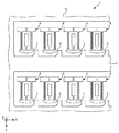
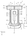
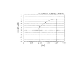
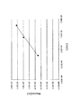
図1は、本発明の第1実施形態に係る振動片基板を示す平面図である。図2は、図1に示す振動片基板が有する振動片の上面図である。図3は、図2に示す振動片を上面側から見たときの透過図である。図4は、図2に示す振動片の断面図である。図5は、屈曲振動時の熱伝導について説明する振動腕の断面図である。図6は、Q値とf1/f0の関係を示すグラフである。図7および図8は、それぞれ、振動片基板の固有振動モードを示す平面図である。図9は、ΔfとQ値の関係を示すグラフである。図10は、Δfと温度の関係を示すグラフである。図11は、CI上昇率と温度の関係を示すグラフである。図12は、CIと温度の関係を示すグラフである。図13は、振動腕の長さと振動腕の幅の関係を示すグラフである。
FIG. 1 is a plan view showing a resonator element substrate according to the first embodiment of the present invention. FIG. 2 is a top view of the resonator element included in the resonator element substrate illustrated in FIG. 1. 3 is a transmission diagram when the resonator element shown in FIG. 2 is viewed from the upper surface side. 4 is a cross-sectional view of the resonator element shown in FIG. FIG. 5 is a cross-sectional view of a vibrating arm for explaining heat conduction during bending vibration. FIG. 6 is a graph showing the relationship between the Q value and f 1 /
なお、各図では、互いに直交する3つの軸として、X軸、Y軸およびZ軸を適宜図示しており、X軸、Y軸およびZ軸が水晶の結晶軸であるX軸(電気軸)、Y軸(機械軸)およびZ軸(光学軸)に対応している。また、以下の説明では、X軸に平行な方向(第2方向)を「X軸方向」、Y軸に平行な方向(第1方向)を「Y軸方向」、Z軸に平行な方向(第3方向)を「Z軸方向」といい、また、各図に図示されているX軸、Y軸およびZ軸の矢印の先端側を「+(プラス)」、基端側を「−(マイナス)」ともいう。また、−Z軸方向側を「上」、+Z軸方向側を「下」ともいう。また、以下の説明では、Z軸方向から見たときの平面視を単に「平面視」ともいう。 In each figure, the X axis, the Y axis, and the Z axis are appropriately illustrated as three axes orthogonal to each other, and the X axis (electrical axis) in which the X axis, the Y axis, and the Z axis are crystal axes of the crystal. , Y axis (mechanical axis) and Z axis (optical axis). In the following description, the direction parallel to the X axis (second direction) is the “X axis direction”, the direction parallel to the Y axis (first direction) is the “Y axis direction”, and the direction parallel to the Z axis ( The third direction) is referred to as the “Z-axis direction”, and the tip side of the X-axis, Y-axis, and Z-axis arrows shown in each figure is “+ (plus)”, and the base end side is “− ( It is also called “minus”. The −Z-axis direction side is also referred to as “upper”, and the + Z-axis direction side is also referred to as “lower”. In the following description, the plan view when viewed from the Z-axis direction is also simply referred to as “plan view”.
図1に示す振動片基板1は、母材である水晶ウエハ10をフォトリソグラフィー技法およびエッチング技法(特に、ウエットエッチング技法)を用いてパターニングしたものであり、少なくとも1つ(本実施形態では複数)の振動片4と、連結部としての折り取り部3と、振動片4に折り取り部3を介して接続されている支持部2と、を有している。このような振動片基板1では、折り取り部3で振動片4を折り取ることで、振動片4を個片化することができる。なお、図2に示すように、折り取り部3で折り取り易いように、折り取り部3にはその一部を脆弱にするための溝部31が設けられている。
A vibrating
本実施形態では、水晶ウエハ10として、Z軸が厚さ方向に一致するZカットの水晶ウエハを用いているが、水晶ウエハ10のカット角は、特に限定されない。例えば、常温近傍における周波数温度変化を小さくする観点から、Z軸を水晶ウエハ10の厚さ方向に対して若干(例えば、±15°未満程度)傾けてもよいし、厚さ方向がX軸やY軸に一致するカットの水晶ウエハを用いてもよい。また、水晶ウエハ10に形成される振動片4の数は、振動片4や水晶ウエハ10のサイズによっても異なり、少なくとも1つあればよい。また、支持部2や折り取り部3の形状は、その機能を果たすことができれば特に限定されない。
In this embodiment, a Z-cut quartz wafer whose Z axis coincides with the thickness direction is used as the
次に、振動片4について説明する。図2や図3に示すように、振動片4は、水晶ウエハ10の一部として構成されている振動体40と、振動体40の表面に配置されている電極と、を有している。また、振動体40は、基部41と、基部41から−Y軸方向に延びている一対の振動腕42、43と、基部41から−Y軸方向に延びており、一対の振動腕42、43の間に位置している支持腕44と、を有している。
Next, the
基部41は、XY平面に沿って広がっており、Z軸方向を厚さ方向とする板状をなしている。そして、この基部41が折り取り部3を介して支持部2に接続されている。振動腕42、43は、X軸方向に並び、かつ、互いに平行となるように、それぞれ、基部41から−Y軸方向に延びている。また、振動腕42、43は、その幅(X軸方向の長さ)がほぼ一定である腕部421、431と、腕部421、431の先端側に配置され、腕部421、431よりも幅の広い広幅部429、439と、を有している。ただし、振動腕42、43の構成としては、特に限定されず、例えば、広幅部429、439を省略してもよい。
The
また、図4に示すように、腕部421は、上面(−Z軸側の主面)に開口する有底の溝部422と、下面(+Z軸側の主面)に開口する有底の溝部423と、を有している。同様に、腕部431は、上面に開口する有底の溝部432と、下面に開口する有底の溝部433と、を有している。このように、振動腕42に溝部422、423を設け、振動腕43に溝部432、433を設けることで、後述するように、屈曲振動によって発生する熱の移動経路が長くなり、断熱的領域において熱弾性損失を低減することができ、振動片4のQ値を向上させることができる。なお、ウエットエッチング技法を用いた場合は、溝部422、423は図4のように矩形形状とはならず、結晶の異方性に起因して複雑な形状となるが、ここではその説明を省略する。
As shown in FIG. 4, the
支持腕44は、基部41から−Y軸方向に延びており、振動腕42、43の間に位置している。振動片4は、振動片基板1から折り取られた後、この支持腕44を介して対象物(例えば、後述する第7実施形態のベース91)に固定される。なお、支持腕44は、省略してもよく、その場合、振動片4は、基部41を介して前述の対象物に固定すればよい。
The
前記電極は、第1駆動電極481および第1駆動端子482と、第2駆動電極491および第2駆動端子492と、を有している。図4に示すように、第1駆動電極481は、振動腕42の上下面(溝部422、423の内面)および振動腕43の両側面に配置されており、第2駆動電極491は、振動腕42の両側面および振動腕43の上下面(溝部432、433の内面)に配置されている。また、図3に示すように、第1駆動端子482は、支持腕44に配置されており、第1駆動電極481と電気的に接続されている。同様に、第2駆動端子492は、支持腕44に配置されており、第2駆動電極491と電気的に接続されている。
The electrodes include a
このような振動片4では、第1駆動電極481および第2駆動電極491の間に駆動信号(例えば、主振動の共振周波数とほぼ等しい周波数の交番電圧)を印加すると、図2および図3中の矢印Aで示すように、振動腕42、43がX軸方向に逆相で(互いに接近、離間を繰り返すように)屈曲振動する。この振動モードは「X軸逆相モード(第2方向逆相モード)」とも言い、振動片4の主振動となる振動モード(固有振動モード)である。このように、X軸逆相モードを主振動とすることで、高いQ値を実現することができ、CI値の小さな振動片4となる。なお、「主振動」とは、振動片4において、電気的に直接駆動される固有振動モードのことを言う。
In such a
また、図4に示すように、振動片4は、一対の振動腕42、43の主振動であるX軸逆相モードに対して対称面となる1つの仮想振動対称面F1(YZ平面)を有している。そのため、振動腕42、43の振動がキャンセルされて、振動エネルギーが基部41に漏洩し難くなる。したがって、Q値の低下を低減することができる。なお、実際には、振動片4は、主振動であるX軸逆相モードに、不要振動であるZ軸逆相モードや捩じれ逆相モード等が結合した状態で振動するが、前述した仮想振動対称面F1は、これら不要振動を排除して、主振動のみを考慮した場合の対称面である。なお、これら不要振動については後述する。また、振動片4は仮想振動対称面F1について、完全な対称形状を有している必要はなく、本発明の効果が得られる範囲において、非対称形状を有していてもよい。具体的には、水晶をウエットエッチングした場合の水晶の異方性に起因して発生する微細な非対称性、電極配線の非対称性などが存在しても、平面視で振動片4の主面の外形が仮想振動対称面F1について、ほぼ対称であればよい。
As shown in FIG. 4, the
主振動であるX軸逆相モードの共振周波数f1としては、特に限定されないが、1×10³[Hz]以上、1×10⁶[Hz]以下であることが好ましく、31.768[kHz]以上、33.768[kHz]以下、すなわち、32.768±1.0[kHz]の範囲内であることがより好ましい。f1をこのような周波数とすることで、利便性の高い振動片4が得られる。
The resonance frequency f 1 in the X-axis reversed phase mode that is the main vibration is not particularly limited, but is preferably 1 × 10 3 [Hz] or more and 1 × 10 6 [Hz] or less, and 31.768 [kHz] ], More preferably 33.768 [kHz] or less, that is, within a range of 32.768 ± 1.0 [kHz]. By setting f 1 to such a frequency, a highly
なお、図3に示すように、第1、第2駆動電極481、491は、折り取り部3を介して支持部2に引き出されており、支持部2に配置されている測定用の端子21、22と電気的に接続されている。そして、振動片基板1上で振動片4の主振動の共振周波数やCI値を測定する際には、測定用の端子21、22が用いられる。このようにすれば、上記の測定を振動片4と非接触で行うことができるため、振動片4が意図せず折り取られてしまうことを低減することができる。
As shown in FIG. 3, the first and
以上、振動片基板1について簡単にその構成を説明した。次に、前述した「熱弾性損失」について振動腕42を例に挙げて簡単に説明する。上述したように、振動腕42がX軸方向に屈曲振動する際、腕部421の一方の側面が収縮すると他方の側面が伸張し、反対に、一方の側面が伸張すると他方の側面が収縮する。振動腕42がGough−Joule効果を発生しない(エネルギー弾性がエントロピー弾性に対して支配的な)場合、図5に示すように、収縮する側面側の温度が上昇し、伸張する側面側の温度が下降するため、両側面の間、つまり腕部421の内部に温度差が発生する。このような温度差から生じる熱移動(図5中の矢印参照)によって振動エネルギーの損失が発生し、これにより振動片4のQ値が低下する。このようなQ値の低下を熱弾性効果とも言い、熱弾性効果によるエネルギーの損失を「熱弾性損失」と言う。
The configuration of the
振動片4のように、屈曲振動モードで振動する振動片において、振動腕42の主振動の共振周波数f1(機械的屈曲振動周波数)が熱緩和周波数f0と一致するときに最小のQ値(Q0)となる。なお、この熱緩和周波数f0は、f0=1/(2πτ)で求めることができる(ただし、式中のπは円周率であり、eをネイピア数とすれば、τは温度差が熱伝導によりe−1倍になるのに要する緩和時間である)。
In a vibrating piece that vibrates in the bending vibration mode, such as the vibrating
前述したように、振動腕42では両側面の間に位置するように溝部422、423が配置されている。そのため、振動腕42の屈曲振動時に生じる両側面の温度差を熱伝導により温度平衡させるための熱の移動経路が溝部422、423を迂回するように形成され、熱の移動経路が両側面間の直線距離(最短距離)よりも長くなる。したがって、振動腕42に溝部422、423を設けていない場合と比較して緩和時間τが長くなり、溝部422、423を有している振動腕42の熱緩和周波数f0が、溝部422、423を有していない振動腕42の熱緩和周波数f0よりも低くなる。
As described above, in the vibrating
図6は、屈曲振動モードの振動片のQ値のf1/f0依存性を表すグラフである。そして、f1/f0<1の領域を「等温的領域」とも言い、この等温的領域ではf1/f0が小さくなるにつれてQ値が高くなる。これは、主振動の共振周波数f1(振動腕の機械的周波数)が低くなる(振動腕の振動が遅くなる)につれて前述のような振動腕内の温度差が生じ難くなるためである。したがって、f1/f0を0(零)に限りなく近づけた際の極限では、等温準静操作となって、熱弾性損失は限りなく0(零)に接近する。一方、f1/f0>1の領域を「断熱的領域」とも言い、この断熱的領域ではf1/f0が大きくなるにつれてQ値が高くなる。これは、主振動の共振周波数f1が高くなるにつれて、各側面の温度上昇・温度効果の切り替わりが高速となり、前述のような熱伝導(熱移動)が生じる時間がなくなるためである。したがって、f1/f0を限りなく大きくした際の極限では、断熱操作となって、熱弾性損失は限りなく0(零)に接近する。本実施形態の振動片4は、このような断熱的領域にある。
FIG. 6 is a graph showing the f 1 /
また、図6において、鎖線で示されている曲線K1は、振動片4のように振動腕に溝部が形成されている場合を示し、実線で示されている曲線K2は、振動腕に溝部が形成されていない場合を示している。曲線K1、K2の形状はほとんど変わらないが、前述のような熱緩和周波数f0の低下に伴って、曲線K1が曲線K2に対して周波数低下方向へシフトしている。したがって、断熱的領域では、振動腕に溝部が形成されている振動片のQ値が、振動腕に溝部が形成されていない振動片のQ値に対して高くなる。よって、前述したように、本実施形態の振動片4は、高いQ値を実現することができる。なお、図6から明らかなように、等温的領域での曲線K1に対応する振動片のQ値と曲線K2に対応する振動片のQ値が等しくなる点、すなわち曲線K1と曲線K2とが交差する点よりf1/f0が小さい領域においては、振動腕に溝部を形成すると熱弾性損失が増大してQ値は劣化する。
In FIG. 6, a curved line K <b> 1 indicated by a chain line indicates a case where a groove is formed on the vibrating arm like the vibrating
ここで、図2および図3に示すように、振動腕42の長さ(Y軸方向の長さ)をL[m]としたとき、振動腕42の基端(振動腕42と基部41との接続部)と、当該基端から振動腕42の先端側へL/3離間した位置との間の領域Syに少なくとも溝部422、423の一部が設けられている。振動時には、振動腕42の基端部の方が先端部よりも大きく変形するため、振動腕42内の温度差が大きくなる。そこで、振動腕42の基端側に溝部422、423を配置することで、溝部422、423を配置することの効果(すなわち、断熱的領域において、熱弾性損失を低減することができる効果)をより高めることができる。
Here, as shown in FIGS. 2 and 3, when the length of the vibrating arm 42 (the length in the Y-axis direction) is L [m], the base end (the vibrating
また、図4に示すように、溝部422、423の深さの合計T’は、特に限定されないが、振動腕42の厚さをTとしたとき、0.8T≦T’<Tの関係を満足することが好ましい。このような関係を満足することでも、溝部422、423を配置することの効果(すなわち、断熱的領域において、熱弾性損失を低減することができる効果)をより高めることができる。ここで、溝部422、423をウエットエッチングで形成すると、水晶の結晶面が現れて、溝部422、423の断面形状が図4のような矩形にはならないが、この場合は、溝部422、423の最も深い部分を前記「深さ」とする。以上のことは、振動腕43の溝部432、433についても同様である。
As shown in FIG. 4, the total depth T ′ of the
また、振動腕42(振動腕43についても同様である。)の腕部421の幅(X軸方向(主振動の振動方向)の長さ)をW[m]としたとき、下記式(1A)を満足することが好ましく、下記式(1B)を満足することがより好ましく、下記式(1C)を満足することがさらに好ましく、下記式(1D)を満足することがますます好ましい。
Further, when the width (length in the X-axis direction (vibration direction of the main vibration)) of the
![]()
![]()
![]()
![]()
![]()
![]()
![]()
![]()
なお、W0は、振動腕42の断面形状が矩形の場合の仮想的な幅(屈曲振動する方向の長さ)であり、振動腕42の質量密度をρ[kg/m3]とし、振動腕42の熱容量をCp[J/(kg・K)]とし、振動腕42の主振動の振動方向に沿った熱伝導率をk[W/(m・K)]とし、円周率をπとし、主振動(X軸逆相モード)の共振周波数をf1[Hz]としたとき、下記の式(2)で表される。
W 0 is an imaginary width (length in the direction of bending vibration) when the cross-sectional shape of the vibrating
上述のような式(1A)〜式(1D)を満足することで、主振動は断熱的領域における振動となり、振動腕42、43に溝部422、423を形成することで、振動腕42、43の屈曲振動によって発生する熱弾性損失に起因するQ値の劣化が低減される。
By satisfying the expressions (1A) to (1D) as described above, the main vibration becomes vibration in the adiabatic region, and by forming the
以上、熱弾性損失について説明した。次に、振動片4の主振動であるX軸逆相モードと、それ以外の不要振動モードとの関係について説明する。
The thermoelastic loss has been described above. Next, the relationship between the X-axis reverse phase mode that is the main vibration of the
まず、不要振動モードについて説明する。振動片4は、上述した主振動(X軸逆相モード)の他にも、温度に対して不安定であって振動漏れが小さくなるように設計されていない、あるいは、小さくすることが困難な固有振動モードである不要振動モードを有している。この不要振動モードの共振周波数が主振動の共振周波数f1と後述する関係を有していると、不要振動モードが主振動と内部共振し、主振動のエネルギーが不要振動モードを介して外部に漏洩してしまう。そのため、主振動のQ値が劣化、それに伴う主振動のCI値の上昇、さらに主振動の共振周波数が安定しない等、振動特性が悪化する。
First, the unnecessary vibration mode will be described. In addition to the main vibration (X-axis reverse phase mode) described above, the
このような不要振動モードとしては、主振動以外の固有振動モードであれば、特に限定されないが、例えば、X軸同相モード(第2方向同相モード)、Z軸逆相モード(第3方向逆相モード)、Z軸同相モード(第3方向同相モード)、捩り逆相モード、捩り同相モード、Z軸基板モード(第3方向基板モード)および基板輪郭モードのうち、少なくとも2つの固有モードの高次モードを含んでいることが好ましい。これら不要振動モードは、数ある不要振動モードの中でも共振周波数が低く、さらに主振動に結合し易い傾向にある。そのため、不要振動としてこれらモードを有することで、以下に述べる本発明の効果がより顕著なものとなる。また、これら不要振動モードは、振動腕22、23以外の部位の振動が低減されるため、振動漏れの小さい振動片2となる。なお、主振動がX軸逆相モードでない場合には、このような不要振動モードにX軸逆相モードが含まれていてもよい。
Such an unnecessary vibration mode is not particularly limited as long as it is a natural vibration mode other than the main vibration, but for example, an X-axis common mode (second direction common mode), a Z-axis reverse phase mode (third direction reverse phase), for example. Mode), Z-axis common mode (third direction common mode), torsional anti-phase mode, torsional common mode, Z-axis substrate mode (third direction substrate mode) and substrate contour mode. Preferably it includes a mode. These unnecessary vibration modes have a low resonance frequency among many unnecessary vibration modes, and tend to be easily coupled to the main vibration. Therefore, by having these modes as unnecessary vibrations, the effects of the present invention described below become more remarkable. In addition, these unnecessary vibration modes reduce the vibrations of the parts other than the vibrating
また、前述した高次モードとして、X軸逆相モード、X軸同相モード、Z軸逆相モードおよびZ軸同相モードのそれぞれの2次モードのうちの少なくとも1つを含んでいることが好ましい。また、前述した高次モードとして、Z軸基板モードおよび前記基板輪郭モードの2次以上、10次以下のモードのうちの少なくとも1つを含んでいることも好ましい。高次モードは、次数が小さい程、主振動に結合し易い傾向にあるため、不要振動として上記の高次モードを有することで、以下に述べる本発明の効果がより顕著なものとなる。 Moreover, it is preferable that the higher-order mode includes at least one of secondary modes of the X-axis reverse phase mode, the X-axis common-mode, the Z-axis reverse-phase mode, and the Z-axis common-mode. Moreover, it is also preferable that the higher-order mode includes at least one of a second-order or higher-order mode of the Z-axis substrate mode and the substrate contour mode. Since the higher order mode tends to be coupled to the main vibration as the order is smaller, the effect of the present invention described below becomes more remarkable by having the above higher order mode as unnecessary vibration.
なお、図7に示すように、X軸同相モードは、振動腕42、43がX軸方向に同相で(互いに同じ方向に)屈曲振動する固有振動モードである。また、Z軸逆相モードは、振動腕42、43がZ軸方向に逆相で屈曲振動する固有振動モードである。また、Z軸同相モードは、振動腕42、43がZ軸方向に同相で屈曲振動する固有振動モードである。また、捩り逆相モードは、振動腕42、43がその軸(振動腕42、43のX軸方向およびZ軸方向に沿った断面の中心を通り、Y軸方向に沿った仮想中心線)まわりに逆相で捩じれる固有振動モードである。また、捩り同相モードは、振動腕42、43がその軸まわりに同相で捩じれる固有振動モードである。
As shown in FIG. 7, the X-axis common mode is a natural vibration mode in which the vibrating
また、図8に示すように、Z軸基板モードは、振動片基板1が全体的にZ軸方向に沿って変形する固有振動モードである。また、基板輪郭モードは、振動片基板1の輪郭がZ軸方向と交差する方向、すなわち、XY面内に変形する固有振動モードである。なお、図7および図8中の矢印や「〇」中に「・」および「〇」中に「×」は、振動腕の変位方向を示し(「〇」中に「・」は紙面手前方向、「〇」中に「×」は紙面奥方向)、実線と破線、あるいは括弧の有無により、交互に繰り返されることを示している。
As shown in FIG. 8, the Z-axis substrate mode is a natural vibration mode in which the
次に、主振動(X軸逆相モード)の共振周波数と上記の不要振動モードの共振周波数との関係について説明する。 Next, the relationship between the resonance frequency of the main vibration (X-axis reversed phase mode) and the resonance frequency of the unnecessary vibration mode will be described.
nを2以上の自然数とし、jを1以上であって前記n以下の自然数としたとき、振動片4は、互いに異なる共振周波数を有するn個の固有振動モード、すなわち、主振動であるX軸逆相モードと少なくとも1つの不要振動モードとを有した振動をし、n個の固有振動モードのそれぞれに対応する共振周波数をfjとし、任意の整数をkj(ただし、kjの2つ以上は0でなく(≠0)、かつ、k1≠0)としたときの、fjとkjの関係において、n個の固有振動モードのうち振動片4の主振動の共振周波数をf1(すなわち、j=1)とし、規格化された周波数差Δfを下記式(3)としたとき、下記式(4)を満足する。
When n is a natural number of 2 or more and j is a natural number of 1 or more and less than or equal to n, the
![]()
![]()
さらに、整数kjと自然数nは、下記式(5)および式(6)を満足する。 Further, the integer k j and the natural number n satisfy the following expressions (5) and (6).
上記式(4)を満足することで、不要振動モードが主振動と内部共振し、主振動のエネルギーが不要振動モードを介して漏洩してしまうことを低減することができる。したがって、振動漏れが少なく、優れた振動特性を発揮することのできる振動片4となる。さらには、振動片基板1上で測定される振動片4の主振動の共振周波数やCI値と、振動片基板1から折り取った状態で測定される振動片4の主振動の共振周波数やCI値と、のズレを小さくすることができ、振動片4の歩留まりの向上を図ることができる。以下、この理由について説明する。
By satisfying the above formula (4), it is possible to reduce the unnecessary vibration mode from internal resonance with the main vibration and the leakage of the energy of the main vibration through the unnecessary vibration mode. Therefore, the
まず、内部共振が発生する条件について説明する。内部共振が発生するには、振動片4が複数の固有振動モード、すなわち、主振動であるX軸逆相モードと少なくとも1つの不要振動モードとを有していることが必要である(条件A1)。さらには、下記式(7)を満足する必要もある(条件A2)。ここで、下記式(7)の「≒」の表現は、下記式(7)の左辺が厳密に零でなくても多少の内部共振が発生してしまう許容量が存在することを意味している。なお、それぞれの固有振動モードの共振周波数をfnとしたとき、少なくとも、fi>0の関係を満足している。また、nは2以上の自然数である。ただし、式(7)中のk1、k2、…、ki、…、knは、整数であり、これらのうちの少なくとも2つは、0でない(≠0)。また、iは、1以上、n以下の自然数である。
First, conditions for causing internal resonance will be described. In order to generate internal resonance, it is necessary that the
![]()
![]()
また、この場合、内部共振に関する条件として必要ではないが、実際に主振動を励振するために、主振動を励振する電気信号の周波数Ω(>0)が、主振動の共振周波数f1とほぼ等しいことが必要である。すなわち、Ω≒f1の関係を満足することが必要である(条件A3)。ここで「ほぼ等しい」としたのは、例えば発振回路により電気的に励振された共振周波数と主振動の機械的に励振された共振周波数とに若干の差があるためであるが、以下では「ほぼ等しい」ではなく「等しい」と表現して同一視する。また、本発明においては主振動のみを直接的に電気的に励振することを想定しているので、厳密には主振動の共振周波数f1は電気的に励振された直列共振周波数であって、これは電気的に短絡された状態で機械的に励振された共振周波数に近似されるから、これらを同一視し、また、容量比γが300以上であれば、電気的に開放された状態で機械的に励振された共振周波数と、電気的に短絡された状態で機械的に励振された共振周波数との差は小さいから、この場合も両者を同一視する。すなわち、主振動の容量比γが300以上であれば、主振動の共振周波数f1は、電気的に励振された直列共振周波数、電気的に短絡された状態で機械的に励振された共振周波数、電気的に開放された状態で機械的に励振された共振周波数、のいずれかであり、主振動の容量比γが300未満であれば、主振動の共振周波数f1は、電気的に励振された直列共振周波数、電気的に短絡された状態で機械的に励振された共振周波数、のいずれかである。 In this case, although not necessary as a condition for internal resonance, in order to actually excite the main vibration, the frequency Ω (> 0) of the electric signal for exciting the main vibration is substantially equal to the resonance frequency f 1 of the main vibration. It is necessary to be equal. That is, it is necessary to satisfy the relationship of Ω≈f 1 (Condition A3). Here, “substantially equal” is because, for example, there is a slight difference between the resonance frequency electrically excited by the oscillation circuit and the resonance frequency mechanically excited of the main vibration. They are identified as “equal” rather than “equal”. In the present invention, since it is assumed that only the main vibration is directly electrically excited, strictly speaking, the resonance frequency f 1 of the main vibration is an electrically excited series resonance frequency, Since this is approximated by a resonance frequency that is mechanically excited in an electrically shorted state, these are identified and if the capacitance ratio γ is 300 or more, the electrically opened state Since the difference between the mechanically excited resonance frequency and the resonance frequency mechanically excited in an electrically shorted state is small, both are also regarded as the same. That is, if the capacity ratio γ of the main vibration is 300 or more, the resonance frequency f 1 of the main vibration is the electrically excited series resonance frequency, or the resonance frequency mechanically excited in the electrically shorted state. The resonance frequency f 1 of the main vibration is mechanically excited in a state of being electrically opened, and if the capacity ratio γ of the main vibration is less than 300, the resonance frequency f 1 of the main vibration is electrically excited The resonance frequency is either a series resonance frequency or a resonance frequency mechanically excited in an electrically shorted state.
また、本発明においては、主振動のみを直接的に電気的に励振することを想定しているので、厳密には不要振動モードの共振周波数は電気的に開放された状態で機械的に励振された共振周波数に近似されるが、不要振動モードの容量比γが300以上であれば、主振動の場合と同様に、電気的に励振された直列共振周波数、電気的に開放された状態で機械的に励振された共振周波数、と同一視する。 In the present invention, it is assumed that only the main vibration is directly electrically excited. Strictly speaking, the resonance frequency of the unnecessary vibration mode is mechanically excited in an electrically open state. If the capacity ratio γ of the unnecessary vibration mode is 300 or more, the series resonance frequency is electrically excited as in the case of the main vibration. It is equated with the resonant frequency excited automatically.
これは、上述した式(4)や後述する式(14)と比較しても、差が十分に小さいためである。なお、主振動モードや不要振動モードの共振周波数は、振動片基板1上で、ヘテロダイン干渉法などによって測定することができる。この際、各振動モードの振動変位が過大とならないようにすれば、大気状態にしたまま測定を行っても、減圧した状態での測定とは誤差が十分に小さいことが発明者らによって確認されている。
This is because the difference is sufficiently small even when compared with the above-described formula (4) and formula (14) described later. Note that the resonance frequency of the main vibration mode and the unnecessary vibration mode can be measured on the vibrating
以上述べた条件A1、A2、A3の全てを満足することで内部共振が発生する。そのため、内部共振を低減するには、条件A1、A2、A3のうちの少なくとも1つを満足しなければよい。そして、振動片基板1は、条件A2を満足しないように構成されている。すなわち、振動片基板1は、上記式(7)の替りに、下記式(8)を満足している。
Internal resonance occurs when all of the conditions A1, A2, and A3 described above are satisfied. Therefore, in order to reduce internal resonance, it is only necessary to satisfy at least one of the conditions A1, A2, and A3. The
![]()
![]()
次に、上記式(7)の「≒」の表現に含有しておいた許容量を規定する。主振動近傍の仮想的な共振周波数をf1’とすると、f1’は、下記式(9)で定義することができる。 Next, the allowable amount contained in the expression “≈” in the above formula (7) is defined. Assuming that the virtual resonance frequency near the main vibration is f 1 ′, f 1 ′ can be defined by the following equation (9).
仮想的な共振周波数f1’は、主振動以外の固有振動の共振周波数から算出され、主振動の共振周波数f1と等しい時に最も強い内部共振が発生する。そして、主振動近傍の仮想的な共振周波数f1’と主振動の共振周波数f1との差を主振動の共振周波数f1で規格化した値をΔfとすると、Δfは、上述した許容量となり、下記式(10)で表すことができる。 The virtual resonance frequency f 1 ′ is calculated from the resonance frequency of the natural vibration other than the main vibration, and the strongest internal resonance occurs when it is equal to the resonance frequency f 1 of the main vibration. When the difference between the virtual resonance frequency f 1 ′ near the main vibration and the resonance frequency f 1 of the main vibration is normalized by the resonance frequency f 1 of the main vibration is Δf, Δf is the allowable amount described above. And can be expressed by the following formula (10).
そして、上記式(10)に式(9)を代入すると、下記式(11)となる。 Substituting equation (9) into equation (10) yields equation (11) below.
そして、上記式(11)を整理すれば上記式(3)が得られる。したがって、上記式(3)を満足することで、内部共振が低減された振動片基板1となることがわかる。ここで、前述したように、式(7)中のk1、k2、…、ki、…、knは、整数であり、これらのうちの少なくとも2つは、0でない。そして、この0でないk(kmとする)を係数とする共振周波数fmは、主振動の振動方向であるX軸と直交するZ軸方向を変位方向する不要振動モード、すなわち、Z軸同相モードまたはZ軸逆相モードの共振周波数とほぼ等しいことが好ましい。言い換えると、振動片基板1の振動片4は、Z軸同相モードまたはZ軸逆相モードを不要振動モードとして有していることが好ましい。また、これらの高次モードを含むことが好ましいが、特に最低次モード、あるいは、2次モードを含むことが好ましい。このような不要振動モードは、他の不要振動モードの中でも、特に、主振動であるX軸逆相モードに結合し易い振動である。そのため、式(3)を満足することによる効果がより大きくなる。
And if the said Formula (11) is rearranged, the said Formula (3) will be obtained. Therefore, it can be seen that satisfying the above expression (3) results in the
また、共振周波数fmは、振動片基板1の特有の不要振動モード、すなわち、振動片基板1から折り取られて個片化された振動片4では発生し得ない不要モードであるZ軸基板モードまたは基板輪郭モードとほぼ等しいことが好ましい。言い換えると、振動片基板1は、Z軸基板モードまたは基板輪郭モードを不要振動モードとして有していることが好ましい。また、これらの高次モードを含むことが好ましいが、特に、2次以上、10次以下の高次モードを含むことが好ましい。前述したように、このような不要振動モードは、個片化された振動片4では発生しない振動モードであるため、このような不要振動モードを有することで、式(3)を満足することによる効果がより大きくなる。すなわち、振動片基板1上で測定される振動片4の主振動の共振周波数やCI値と、振動片基板1から折り取った状態で測定される振動片4の主振動の共振周波数やCI値と、のズレを小さくすることができ、振動片4の歩留まりの向上を図ることができる。なお、この場合は当然ながら振動片基板1の特有の不要振動モードの共振周波数fmと、主振動の共振周波数f1とが一致しないようにすることは、従来知られている技術であって、本発明には含まれない。
The resonance frequency f m is a Z-axis substrate that is a unique unnecessary vibration mode of the
特に、本実施形態では、平面視で、折り取り部3が一対の振動腕42、43の主振動の仮想振動対称面F1から離間して配置されている。そのため、振動片4の主振動を励振させた際の振動バランスが悪く、振動腕42、43の振動エネルギーが折り取り部3を介して支持部2に漏洩し易い。その結果、振動片基板1は、前述のようなZ軸基板モードおよび基板輪郭モードと結合し易い構成となる。そのため、式(3)を満たすことによる効果がより大きくなる。すなわち、振動片基板1上で測定される振動片4の主振動の共振周波数やCI値と、振動片基板1から折り取った状態で測定される振動片4の主振動の共振周波数やCI値と、のズレを小さくすることができ、振動片4の歩留まりの向上を図ることができる。
In particular, in the present embodiment, the folded
また、振動片基板1は、主振動の共振周波数f1の10倍以下の共振周波数fjを有する不要振動モードを有していることが好ましく、3倍以下の共振周波数fjを有する不要振動モードを有していることがより好ましい。このような周波数の不要振動モードは、主振動と強く結合するおそれがある。そのため、式(3)を満足することによる効果がより大きくなる。
Also,
また、振動片基板1は、主振動の共振周波数f1の3倍以下の共振周波数を有する不要モードすべてに対して上記式(4)を満足していることが好ましく、10倍以下の共振周波数を有する不要モードすべてに対して上記式(4)を満足していることがより好ましい。このような関係を満足することで、主振動と強く結合し易い不要モードとの内部共振が発生するおそれをより低減することができる。
The
また、主振動モードの共振周波数f1よりも低周波の共振周波数を有する不要振動モードを有していることが好ましい。即ち、主振動モードの共振周波数f1に対してf2<f1の関係を満足する共振周波数f2を有する不要振動モードを有していることが好ましい。また、f1/10≦f2<f1の関係を満足する共振周波数f2を有する不要振動モードを有していることがより好ましく、f1/3≦f2<f1の関係を満足する共振周波数f2を有する不要振動モードを有していることがさらに好ましい。これは、不要振動モードの中でも特に、主振動モードよりも低周波であって、主振動モードの共振周波数f1に近い共振周波数を有する不要振動モードが主振動と内部共振し易いためである。
Moreover, it is preferable to have an unnecessary vibration mode having a resonance frequency lower than the resonance frequency f 1 of the main vibration mode. That is, it is preferable to have an unnecessary vibration mode having a resonant frequency f 2 to satisfy the relationship of f 2 <f 1 with respect to the resonance frequency f 1 of the main vibration modes. It is more preferable to have an unnecessary vibration mode having a resonant frequency f 2 to satisfy the relation of f 1/10 ≦ f 2 <
なお、前述したように、振動片基板1は、さらに、上記式(5)を満足している。式(5)では内部共振次数の限定を行っている。この内部共振次数は、非線形次数と関係があり、非線形次数が小さい条件程、非線形性が小さくても内部共振の影響が大きくなる。そのため、式(5)と式(4)とを満足することで、特に、内部共振の影響が大きい条件において、内部共振が発生するおそれを効果的に小さくすることができる。
As described above, the
なお、振動片基板1は、式(5)を満足していれば、特に限定されないが、下記式(12)を満足するのがより好ましく、下記式(13)を満足するのがさらに好ましい。これにより、低次の非線形性が顕著に現れる振動片基板1においても主振動と不要振動モードとの結合が生じ難く、不要振動モードを介した主振動の振動漏れを小さくすることができる。
The
また、nは、3以下であるのが好ましく、2であるのがより好ましい。nの値が小さい程、内部共振し易い傾向があり、本発明による効果が大きいためである。 Further, n is preferably 3 or less, and more preferably 2. This is because as the value of n is smaller, internal resonance tends to occur and the effect of the present invention is greater.
また、振動片基板1では、前述したように、式(4)を満足している。|Δf|が0に近過ぎると、主振動との内部共振によって不要振動モードが発生し易くなるため、式(4)を満足することで、不要振動モードの発生を低減することができる。以下、このことについて簡単に説明する。また、以下では、説明の便宜上、不要振動モードがX軸同相モードである場合について代表して説明するが、X軸同相モード以外の不要振動モードであっても同様の関係を満足することが確認されている。
In addition, as described above, the
図9は、|Δf|とQ値の関係を示すグラフである。図9は、主振動モードであるX軸逆相モードの共振周波数f1と不要振動モードであるX軸同相モードの共振周波数f2とが1:1で近接する場合のΔf、すなわちΔf=(f2−f1)/f1の場合の実測値であるが、1:1以外の結合においても同様な効果を得ることを確認している。なお、図9では、Q値をその最大値で規格化した指数を縦軸として示している(すなわち、指数の最大値は1となる)。また、図9は、振動腕42、43の長さLが930μm、振動腕42、43の幅Wが60μm、振動片4の全長が1160μm、全幅が520μmのサイズを有する振動片4を用いた実測値である。
FIG. 9 is a graph showing the relationship between | Δf | and the Q value. FIG. 9 shows Δf in the case where the resonance frequency f 1 of the X-axis opposite phase mode which is the main vibration mode and the resonance frequency f 2 of the X-axis common mode which is the unnecessary vibration mode are close to each other by 1: 1, that is, Δf = ( Although it is an actual measurement value in the case of f 2 −f 1 ) / f 1 , it has been confirmed that a similar effect is obtained even in a coupling other than 1: 1. In FIG. 9, an index obtained by normalizing the Q value with the maximum value is shown on the vertical axis (that is, the maximum value of the index is 1). Further, in FIG. 9, the vibrating
図9から分かるように、式(4)を満足すれば、規格化した指数の最大値の60%以上を発揮することができ、不要振動モードを十分に低減することができる。なお、振動片基板1は、式(4)を満足していれば、特に限定されないが、下記式(14A)を満足することが好ましく、下記式(14B)を満足することがより好ましく、下記式(15C)を満足することがさらに好ましい。これにより、不要振動モードが主振動との内部共振によって発生することをさらに効果的に低減することができ、振動漏れが増大するおそれをさらに低減することができる。
As can be seen from FIG. 9, if Expression (4) is satisfied, 60% or more of the maximum value of the normalized index can be exhibited, and the unnecessary vibration mode can be sufficiently reduced. The
式(4)や下記式(14A)〜(14C)は、常温において満足していれば常温における主振動のエネルギー漏洩を低減することができる。また、常温以外を含めた動作温度範囲、例えば一般的には−40℃から85℃の範囲、車載用においては−40℃から150℃の範囲すべてにおいて式(4)や下記式(14A)〜(14C)を満足していれば、その温度範囲内において、主振動のエネルギー漏洩を低減することができる。 If Expression (4) and the following Expressions (14A) to (14C) are satisfied at room temperature, energy leakage of main vibration at room temperature can be reduced. Further, in the operating temperature range including other than normal temperature, for example, generally in the range of −40 ° C. to 85 ° C., and in the case of in-vehicle use, in all of the range of −40 ° C. to 150 ° C., the formula (4) and the following formula (14A) If (14C) is satisfied, the energy leakage of the main vibration can be reduced within the temperature range.
![]()
![]()
![]()
![]()
![]()
![]()
次に、固有振動モードの数(n)が2、3、4である場合について、いくつかの具体例を挙げる。なお、以下では、下記式(15)の関係を満足するものとする。また、主振動の共振周波数をf1とし、不要振動モードの周波数をf2とする。 Next, some specific examples will be given for the case where the number (n) of natural vibration modes is 2, 3, and 4. In the following, it is assumed that the relationship of the following formula (15) is satisfied. Further, the resonance frequency of the main vibration and f 1, the frequency of the undesired oscillation mode and f 2.
[具体例1:m=3、n=2]
この場合には、上記式(9)から下記式(16)を導くことができる。
[Specific Example 1: m = 3, n = 2]
In this case, the following formula (16) can be derived from the above formula (9).
そして、例えば、k1=1、k2=−2の場合には、f1’=2f2となり、式(10)から下記式(17)を導くことができ、k1=2、k2=−1の場合には、f1’=f2/2となり、式(10)から下記式(18)を導くことができる。 For example, when k 1 = 1 and k 2 = −2, f 1 ′ = 2f 2 , and the following equation (17) can be derived from the equation (10), and k 1 = 2 and k 2 = in the case of -1, f 1 '= f 2/ 2 , and the can be derived the following equation from equation (10) to (18).
また、本発明では式(5)(あるいは式(13)、式(15))を満足する必要があるため、n=2の場合には3≦|k1|+|k2|でなければならない。即ち、k1=1、k2=−1の条件は本発明には含まれない。このような条件では、上記式(16)からf1’=f2、さらに上記式(10)からΔf=(f2−f1)/f1が導かれ、|Δf|≒0となる条件は、結局、f2≒f1となる。これは主振動モードの共振周波数f1と不要振動モードの共振周波数f2とが近接して結合する従来から知られていた結合を表現している。本発明ではこのような従来から知られていた主振動モードの共振周波数と不要振動モードの共振周波数が近接することで発生する結合からは全く知り得ない結合状態を開示したものである。 In the present invention, since it is necessary to satisfy the formula (5) (or the formula (13) and the formula (15)), when n = 2, if 3 ≦ | k 1 | + | k 2 | Don't be. That is, the conditions of k 1 = 1 and k 2 = −1 are not included in the present invention. Under such conditions, f 1 ′ = f 2 is derived from the above equation (16), and Δf = (f 2 −f 1 ) / f 1 is derived from the above equation (10), so that | Δf | ≈0. In the end, f 2 ≈f 1 . It expresses the main oscillation mode and the resonance frequency f 1 and the resonance frequency f 2 of the unnecessary vibration mode has been known to bind in close proximity coupling. The present invention discloses a coupling state that cannot be known at all from the coupling that occurs when the resonance frequency of the main vibration mode and the resonance frequency of the unnecessary vibration mode that are conventionally known are close to each other.
また、本発明では、主振動を励振する電気信号は、主振動の共振周波数と等しい周波数Ωを有する正弦波信号のみ、あるいはそれに近い状態の電気信号が入力されることを前提としている。例えば、矩形波が電気信号として入力された場合には、周波数Ωの正弦波に加えて、Ωの奇数倍(3Ω、5Ω、…)の周波数成分を有する正弦波が入力されることになり、前記Ωの奇数倍の周波数のうちの一つ(特に数字が小さい3Ωは振幅が大きい為に影響も大きい)と不要振動モードの内の一つの共振周波数が近接した場合に、前記不要振動モードが励振されてしまうが、本発明ではこれを含まない。また、デューティー比が50%以外の場合には前記Ωの偶数倍(2Ω、4Ω、…)の周波数成分を有する正弦波が入力されることになるが、これも本発明では含まない。 In the present invention, the electrical signal for exciting the main vibration is based on the assumption that only a sine wave signal having a frequency Ω equal to the resonance frequency of the main vibration or an electric signal in a state close thereto is input. For example, when a rectangular wave is input as an electrical signal, a sine wave having a frequency component of an odd multiple of Ω (3Ω, 5Ω,...) Is input in addition to a sine wave of frequency Ω. When one of the frequencies of odd multiples of Ω (particularly 3Ω having a small number has a large influence due to its large amplitude) and one of the unnecessary vibration modes is close to each other, the unnecessary vibration mode is This is not included in the present invention. When the duty ratio is other than 50%, a sine wave having an even multiple (2Ω, 4Ω,...) Of the Ω is input, but this is not included in the present invention.
[具体例2:m=3、n=3]
この場合には、上記式(9)から下記式(19)を導くことができる。
[Specific example 2: m = 3, n = 3]
In this case, the following formula (19) can be derived from the above formula (9).
そして、例えば、k1=−1、k2=k3=1の場合には、f1’=f2+f3となり、式(10)から下記式(20)を導くことができ、k1=k3=−1、k2=1の場合には、f1’=f2−f3となり、式(10)から下記式(21)を導くことができる。 For example, when k 1 = −1 and k 2 = k 3 = 1, f 1 ′ = f 2 + f 3 , and the following equation (20) can be derived from equation (10), and k 1 = K 3 = −1, k 2 = 1, f 1 ′ = f 2 −f 3 , and the following formula (21) can be derived from the formula (10).
[具体例3:m=4、n=2]
例えば、k1=−1、k2=3の場合には、f1’=3f2となり、式(10)から下記式(22)を導くことができ、k1−3、k2=1の場合には、f1’=f2/3となり、式(10)から下記式(23)を導くことができる。
[Specific Example 3: m = 4, n = 2]
For example, when k 1 = −1 and k 2 = 3, f 1 ′ = 3f 2 , and the following formula (22) can be derived from the formula (10), and k 1 −3, k 2 = 1 in the
[具体例4:m=4、n=3]
例えば、k1=−2、k2=k3=1の場合には、f1’=(f2+f3)/2となり、式(10)から下記式(24)を導くことができ、k1=−2、k2=1、k3=−1の場合には、f1’=(f2−f3)/2となり、式(10)から下記式(25)を導くことができ、k1=−1、k2=2、k3=1の場合には、f1’=2f2+f3となり、式(10)から下記式(26)を導くことができ、k1=−1、k2=2、k3=−1の場合には、f1’=2f2−f3となり、式(10)から下記式(27)を導くことができる。
[Specific Example 4: m = 4, n = 3]
For example, when k 1 = −2 and k 2 = k 3 = 1, f 1 ′ = (f 2 + f 3 ) / 2, and the following equation (24) can be derived from equation (10), When k 1 = −2, k 2 = 1, and k 3 = −1, f 1 ′ = (f 2 −f 3 ) / 2, and the following equation (25) can be derived from equation (10). When k 1 = −1, k 2 = 2 and k 3 = 1, f 1 ′ = 2f 2 + f 3 , and the following formula (26) can be derived from the formula (10), and k 1 When = 1, k 2 = 2 and k 3 = −1, f 1 ′ = 2f 2 −f 3 , and the following equation (27) can be derived from the equation (10).
[具体例4:m=4、n=4]
この場合には、上記式(9)から下記式(28)を導くことができる。
[Specific Example 4: m = 4, n = 4]
In this case, the following formula (28) can be derived from the above formula (9).
そして、例えば、k1=−1、k2=k3=k4=1の場合には、f1’=f2+f3+f4となり、式(10)から下記式(29)を導くことができ、k1=k3=−1、k2=k4=1の場合には、f1’=f2−f3+f4となり、式(10)から下記式(30)を導くことができ、k1=k4=−1、k2=k3=1の場合には、f1’=f2+f3−f4となり、式(10)から下記式(31)を導くことができ、k1=k3=k4=−1、k2=1の場合には、f1’=f2−f3−f4となり、式(10)から下記式(32)を導くことができる。 For example, when k 1 = −1 and k 2 = k 3 = k 4 = 1, f 1 ′ = f 2 + f 3 + f 4 , and the following formula (29) is derived from the formula (10). When k 1 = k 3 = −1 and k 2 = k 4 = 1, f 1 ′ = f 2 −f 3 + f 4 , and the following formula (30) is derived from the formula (10). When k 1 = k 4 = −1 and k 2 = k 3 = 1, f 1 ′ = f 2 + f 3 −f 4 , and the following equation (31) is derived from equation (10). When k 1 = k 3 = k 4 = −1 and k 2 = 1, f 1 ′ = f 2 −f 3 −f 4 , and the following equation (32) is derived from equation (10). be able to.
次に、固有振動モードを特定した場合について、いくつかの具体例を挙げる。
[具体例1]
例えば、振動片基板1に配置されている振動片4がX軸逆相モードの主振動(共振周波数f1=32.768kHz)を有し、不要振動モードとしてZ軸同相モード(共振周波数f2=20.49kHz)を有している場合には、最も強く内部共振が起きる条件として、k1f1+k2f2=0を満足する必要がある。しかしながら、m≦10(式(5)参照)の範囲内で上記式を満足する{k1、k2}の組み合わせは存在しない。したがって、この場合は、上記式(8)を満足し、また、|Δf|が最も小さくなる条件であるm=3を例にとれば、上記式(17)から|Δf|=25.06%となり、不要振動モードが主振動に結合し難いことが分かる。
Next, some specific examples will be given for the case where the natural vibration mode is specified.
[Specific Example 1]
For example, the
[具体例2]
例えば、振動片基板1に配置されている振動片4がX軸逆相モードの主振動(共振周波数f1=32.768kHz)を有し、不要振動モードとしてZ軸逆相モード(共振周波数f2=82.05kHz)を有している場合には、最も強く内部共振が起きる条件として、k1f1+k2f2=0を満足する必要がある。しかしながら、m≦10(式(5)参照)の範囲内で上記式を満足する{k1、k2}の組み合わせは存在しない。したがって、この場合は、上記式(8)を満足し、また、|Δf|が最も小さくなる条件であるm=3を例にとれば、上記式(18)から|Δf|=25.20%となり、不要振動モードが主振動に結合し難いことが分かる。
[Specific Example 2]
For example, the
以上、具体例を挙げて説明した。なお、振動片4のサイズとしては、特に限定されないが、振動腕42、43の長さLは、0.1mm≦L≦0.9mmの関係を満足することが好ましく、0.2mm≦L≦0.7mmの関係を満足することがより好ましく、0.3mm≦L≦0.5mmの関係を満足することがさらに好ましい。また、振動腕42、43の厚さTは、50μm≦T≦150μmの関係を満足することが好ましく、80μm≦T≦140μmの関係を満足することがより好ましく、120μm≦T≦130μmの関係を満足することがさらに好ましい。また、振動腕42、43の腕部421、431の幅Wは、12.8μm≦W≦50μmであることが好ましく、15μm≦W≦45μmであることがより好ましく、20μm≦W≦30μmであることがさらに好ましい。また、腕部421(431)の溝部422、423(432、433)の両脇に残る主面の幅W’は、1μm≦W’≦6μmの関係を満足することが好ましく、1μm≦W’≦4.5μmの関係を満足することがより好ましく、1μm≦W’≦3μmの関係を満足することがさらに好ましい。また、腕部421(431)の広幅部429(439)の長さL’は、0.1≦L’/L≦0.5の関係を満足することが好ましく、0.1≦L’/L≦0.35の関係を満足することがより好ましく、0.1≦L’/L≦0.25の関係を満足することがさらに好ましい。また、広幅部429(439)の幅W”および長さL’は、L’<W”の関係を満足することが好ましい。
In the above, a specific example was given and demonstrated. The size of the vibrating
振動片4を上記のようなサイズとすることで、比較的小型な振動片4となる。そのため、水晶ウエハをウエットエッチングでパターニングすることにより振動体40を得る場合には、特に、水晶基板のエッチング異方性に起因して、形状の対称性が損なわれて非線形性が増大して主振動と不要振動が内部共振を発生し易く、よって振動漏れが小さくなるように設計されていない(あるいは小さくすることが困難な)不要振動を介して主振動のエネルギーが外部に漏洩してしまう。特に、幅W’が比較的狭く設定されていること、広幅部429、439を有していること、さらに、L’<W”の関係を満足することで、振動腕42、43の横断面形状の非対称性が発生し易く、上記の問題がさらに顕著となる。したがって、このような不要振動が発生し易いサイズの振動片4を備える振動片基板1において、上述した構成とすることによって、上述した効果をより顕著に発揮することができる。
By setting the size of the vibrating
さらに、音叉型の振動素子のように、同一方向に延びる一対の振動腕のみを振動腕として含む場合には、基部を基準に前述の延びる方向とは反対方向に対する形状の対称性はとれないので、本発明はより効果的に作用する。また、水晶では結晶面が複雑に形成されるので、水晶を基材としてウエットエッチングすることで振動素子を形成した場合には、本発明はさらに効果的に作用する。 Further, when only a pair of vibrating arms extending in the same direction is included as a vibrating arm, such as a tuning fork type vibrating element, the symmetry of the shape with respect to the direction opposite to the extending direction described above cannot be taken with respect to the base. The present invention works more effectively. In addition, since the crystal plane is complicatedly formed in quartz, the present invention works more effectively when the vibration element is formed by wet etching using quartz as a base material.
次に、前述の式(4)を満足することによる効果(前述では述べていない効果)について説明する。図10は、正常サンプルS1および2つの異常サンプルS2、S3に関するΔfと環境温度の関係を示すグラフである。ここでのΔfは、上記式(18)に相当し、主振動モードであるX軸逆相モードの共振周波数をf1(=32.768kHz)とし、主振動と内部共振していると考えられる不要振動モードであるZ軸同相モードの共振周波数をf2とする。すなわち、ここでのΔfは、f2が65.536kHz(f1の2倍の周波数)からどれだけずれているかを示す値とも言える。 Next, effects (effects not described above) obtained by satisfying the above-described expression (4) will be described. FIG. 10 is a graph showing the relationship between Δf and environmental temperature regarding the normal sample S1 and the two abnormal samples S2 and S3. Δf here corresponds to the above equation (18), and the resonance frequency of the X-axis antiphase mode, which is the main vibration mode, is f 1 (= 32.768 kHz), and is considered to be in internal resonance with the main vibration. the resonant frequency of the Z-axis common mode is unnecessary oscillation mode and f 2. That is, Δf here can be said to be a value indicating how much f 2 is deviated from 65.536 kHz (a frequency twice that of f 1 ).
一方、図11は、正常サンプルS1および2つの異常サンプルS2、S3に関するCI上昇率と環境温度の関係を示すグラフであり、図12は、正常サンプルS1および2つの異常サンプルS2、S3に関するCIと環境温度の関係を示すグラフである。これら図11および図12は、−50°におけるCI値を基準(0)として、この基準からどれだけCI上昇率(CI値)が変化しているかを示すグラフである。 On the other hand, FIG. 11 is a graph showing the relationship between the CI increase rate for the normal sample S1 and the two abnormal samples S2 and S3 and the environmental temperature, and FIG. 12 shows the CI for the normal sample S1 and the two abnormal samples S2 and S3. It is a graph which shows the relationship of environmental temperature. FIG. 11 and FIG. 12 are graphs showing how much the CI increase rate (CI value) changes from the reference value (0) with respect to the CI value at −50 °.
図11および図12に示すように、正常サンプルS1ではCI上昇率(CI値)が穏やかに上昇しているのに対して、異常サンプルS2では35℃付近でCI上昇率が異常に上昇しており、異常サンプルS3では110℃付近でCI上昇率が異常に上昇している。そして、異常サンプルS2、S3について、CI上昇率が異常に上昇している温度は、図10に示すΔfが0%となる温度とほぼ一致している。そのため、上記式(4)の関係を満足することで(すなわち、Δf=0%付近を除くことで)、このようなCI上昇率(CI値)の異常な上昇を低減することができることがわかる。なお、振動片基板1は、振動片4の動作温度範囲(−40℃から85℃、−40℃から150℃等)のいずれかの温度域において式(4)を満足していれば、その温度域を用いることで上述したCI値の異常な上昇が発生するおそれを低減することができる。好ましくは、前記動作温度範囲のすべての温度において式(4)を満足していれば、動作温度範囲すべてにおいて上述したCI値の異常な上昇が発生するおそれを低減することができる。
As shown in FIGS. 11 and 12, the CI increase rate (CI value) increases moderately in the normal sample S1, whereas the CI increase rate abnormally increases around 35 ° C. in the abnormal sample S2. In the abnormal sample S3, the CI increase rate is abnormally increased around 110 ° C. For the abnormal samples S2 and S3, the temperature at which the CI increase rate is abnormally increased substantially matches the temperature at which Δf shown in FIG. 10 is 0%. Therefore, it is understood that such an abnormal increase in the CI increase rate (CI value) can be reduced by satisfying the relationship of the above formula (4) (that is, by excluding the vicinity of Δf = 0%). . Note that if the
また、振動片基板1では、振動片4のQ値をQとしたとき、下記式(33)の関係を満足し、式(33)中のf0maxは、下記式(34)の関係を満足し、式(34)中のWeminは、下記式(35)の関係を満足する。これら関係を満足することで、小型で十分に高いQ値を有する振動片4となる。
Further, in the
![]()
![]()
ただし、式(33)、(34)、(35)中の、A=7.3690×10⁻²、B=1.2544×10⁻⁵、C=1.1〜1.3、f0max[Hz]は振動腕42、43(腕部421、431)の断面形状を熱弾性損失が等しくなるように矩形に置き換えた際の振動腕42、43の等価腕幅Weが、後述する最小値Weminのときに熱弾性損失が最大となる共振周波数(熱緩和周波数)、L[m]は振動腕42、43の延在方向に関する長さ、ρ[kg/m3]は振動腕42、43の質量密度、Cp[J/(kg・K)]は振動腕42、43の熱容量、c[N/m2]は振動腕42、43の延在方向に関する弾性定数、α[1/K]は振動腕42、43の延在方向に関する熱膨張係数、Θ[K]は環境温度、k[W/(m・K)]は振動腕42、43の主振動の振動方向に沿った熱伝導率、πは円周率である。
However, in the formulas (33), (34), and (35), A = 7.3690 × 10 −2 , B = 1.2544 × 10 −5 , C = 1.1 to 1.3, f0max [Hz ], The equivalent arm width We of the vibrating
以下、式(33)の導出方法について説明する。まず、下記の表1に、小型化を図るために有効と考えられる振動腕42、43の長さLと、その長さのときに求められるQ値の最小値Qminとの関係を示す。このような関係を満足することは、小型で、かつ、より高いQ値を有する振動片4を有する振動片基板1が得られるということである。したがって、例えば、振動片4を用いた発振回路の消費電力を低減することができ、また、小型化によって製造時に発生するCO2の排出を低くすることができるから、環境負荷の小さい振動片基板1となる。
Hereinafter, the derivation method of Formula (33) is demonstrated. First, Table 1 below shows the relationship between the length L of the vibrating
f1=32.768kHz、QminをQTED(熱弾性損失のみを考慮したQ値)として下記式(36)、(37)に代入し、f1>f0の関係を満足する幅Wを算出することで、長さLに対する最小値Weminを算出する。この最小値Weminの算出結果を下記の表3に示す。なお、式(36)、(37)中の各数値は、下記の表2に示す通りである。前述したように、f0は、熱緩和周波数であり、f1>f0(f1/f0>1)は、振動片4が断熱的領域にあることを意味している。
Substituting f 1 = 32.768 kHz, Qmin into Q TED (Q value considering only thermoelastic loss) into the following formulas (36) and (37), and calculating the width W satisfying the relationship of f 1 > f0 Thus, the minimum value Wemin for the length L is calculated. The calculation result of the minimum value Wemin is shown in Table 3 below. The numerical values in the formulas (36) and (37) are as shown in Table 2 below. As described above, f0 is the thermal relaxation frequency, and f 1 > f0 (f 1 / f0> 1) means that the
長さLに対する最小値Weminは、図13に示すグラフのようになり、その近似式は、Wemin=7.3690×10⁻²L+1.2544×10⁻⁵となる。さらに、この式の右辺に係数C(ただし、Cは1.1〜1.3)をかけることで上記の式(35)が得られる。この式(35)により、振動腕42、43の長さLに対する振動腕42、43の幅Wの最小値Weminを算出することができる。さらに、得られた最小値Weminを式(37)に代入することで、f0を算出することができる。なお、f0は、振動腕42、43の幅Wが最小値Weminのときに熱弾性損失が最大となる共振周波数である(=f0max)。前述したように、本実施形態では、断熱的領域(f1>f0)に限定しているため、f0によりQ値の下限値であるQmin(QTED)を決定することができる。すなわち、式(36)にf0を代入することで、Qminを算出することができる。そして、Q≧Qminの関係を満足すれば、十分に高いQ値が得られることから、式(33)が導き出される。
The minimum value Wemin with respect to the length L is as shown in the graph of FIG. 13, and its approximate expression is Wemin = 7.3690 × 10 −2 L + 1.2544 × 10 −5 . Further, the above equation (35) is obtained by multiplying the right side of this equation by a coefficient C (where C is 1.1 to 1.3). From this equation (35), the minimum value Wemin of the width W of the vibrating
<第2実施形態>
次に、本発明の第2実施形態に係る振動片基板について説明する。
Second Embodiment
Next, a resonator element substrate according to a second embodiment of the invention will be described.
図14は、本発明の第2実施形態に係る振動片基板の平面図である。なお、図14では、説明の便宜上、電極の図示を省略している。 FIG. 14 is a plan view of the resonator element substrate according to the second embodiment of the invention. In FIG. 14, the electrodes are not shown for convenience of explanation.
以下、第2実施形態の振動片基板について、前述した第1実施形態との相違点を中心に説明し、同様の事項については、その説明を省略する。 Hereinafter, the resonator element substrate of the second embodiment will be described with a focus on the differences from the first embodiment described above, and description of similar matters will be omitted.
本発明の第2実施形態にかかる振動片基板は、振動片の構成が異なる以外は、前述した第1実施形態と同様である。なお、前述した実施形態と同様の構成には、同一符号を付してある。 The resonator element substrate according to the second embodiment of the present invention is the same as that of the first embodiment described above except that the structure of the resonator element is different. In addition, the same code | symbol is attached | subjected to the structure similar to embodiment mentioned above.
図14に示すように、本実施形態の振動片基板1では、平面視で、折り取り部3が仮想振動対称面F1と重なって配置されている。本実施形態では、振動片4の支持腕44の先端部と支持部2とを連結するように折り取り部3が配置されているが、折り取り部3の配置としては、仮想振動対称面F1と重なって配置されていれば特に限定されず、例えば、基部41と支持部2とを連結するように配置されていてもよい。このように、折り取り部3を仮想振動対称面F1と重なるように配置することで、振動腕42、43の振動エネルギーが折り取り部3を介して支持部2に漏洩し難くなり、隣接する図示されていない振動片4や、振動片基板1が有するZ軸基板モードおよび基板輪郭モードと内部共振し難い構成となる。そのため、振動片基板1上で測定される振動片4の主振動の共振周波数やCI値と、振動片基板1から折り取った状態で測定される振動片4の主振動の共振周波数やCI値と、のズレを小さくすることができ、振動片4の歩留まりの向上を図ることができる。
As shown in FIG. 14, in the
以上のような第2実施形態によっても、前述した第1実施形態と同様の効果を発揮することができる。 According to the second embodiment as described above, the same effect as that of the first embodiment described above can be exhibited.
<第3実施形態>
次に、本発明の第3実施形態に係る振動片基板について説明する。
<Third Embodiment>
Next, a resonator element substrate according to a third embodiment of the invention is described.
図15は、本発明の第3実施形態に係る振動片基板の平面図である。なお、図15では、説明の便宜上、電極の図示を省略している。 FIG. 15 is a plan view of a resonator element substrate according to the third embodiment of the invention. In FIG. 15, illustration of electrodes is omitted for convenience of explanation.
以下、第3実施形態の振動片基板について、前述した第1実施形態との相違点を中心に説明し、同様の事項については、その説明を省略する。 Hereinafter, the resonator element substrate of the third embodiment will be described focusing on the differences from the first embodiment described above, and description of similar matters will be omitted.
本発明の第3実施形態にかかる振動片基板は、振動片の構成が異なる以外は、前述した第1実施形態と同様である。なお、前述した実施形態と同様の構成には、同一符号を付してある。 The resonator element substrate according to the third embodiment of the present invention is the same as that of the first embodiment described above except that the structure of the resonator element is different. In addition, the same code | symbol is attached | subjected to the structure similar to embodiment mentioned above.
図15に示すように、本実施形態の振動片4では、振動腕42、43に溝部が形成されておらず、振動腕42、43の上面および下面がそれぞれ平坦面で構成されている。すなわち、本実施形態の振動片4は、前述した第1実施形態の構成から溝部(422、423、432、433)を省略した構成となっている。
As shown in FIG. 15, in the
また、前述した第1実施形態の振動片4が断熱的領域にあって、式(1)を満足しているのに対して、本実施形態の振動片4は、等温的領域にあって、下記式(38A)を満足している。下記式(38A)を満足することで等温的領域となり、Q値の劣化を低減した小型の振動片4とすることができる。さらに、この効果をより顕著なものとするために、下記式(38B)を満足していることが好ましく、下記式(38C)を満足することがより好ましく、下記式(38D)を満足することがさらに好ましい。
In addition, the
![]()
![]()
![]()
![]()
![]()
![]()
![]()
![]()
以上のような第3実施形態によっても、前述した第1実施形態と同様の効果を発揮することができる。 According to the third embodiment as described above, the same effects as those of the first embodiment described above can be exhibited.
<第4実施形態>
次に、本発明の第4実施形態に係る振動片基板について説明する。
<Fourth embodiment>
Next, a resonator element substrate according to a fourth embodiment of the invention is described.
図16は、本発明の第4実施形態に係る振動片基板の平面図である。図17および図18は、それぞれ、図16に示す振動片基板が有する振動片の作動を説明する図である。なお、図15では、説明の便宜上、電極の図示を省略している。 FIG. 16 is a plan view of a resonator element substrate according to the fourth embodiment of the invention. FIGS. 17 and 18 are diagrams for explaining the operation of the resonator element included in the resonator element substrate illustrated in FIG. 16. In FIG. 15, illustration of electrodes is omitted for convenience of explanation.
以下、第4実施形態の振動片基板について、前述した第1実施形態との相違点を中心に説明し、同様の事項については、その説明を省略する。 Hereinafter, the resonator element substrate according to the fourth embodiment will be described with a focus on differences from the first embodiment described above, and description of similar matters will be omitted.
本発明の第4実施形態にかかる振動片基板は、振動片の構成が異なる以外は、前述した第1実施形態と同様である。なお、前述した実施形態と同様の構成には、同一符号を付してある。 The resonator element substrate according to the fourth embodiment of the present invention is the same as that of the first embodiment described above except that the structure of the resonator element is different. In addition, the same code | symbol is attached | subjected to the structure similar to embodiment mentioned above.
図16に示す本実施形態の振動片6は、角速度を検出することのできる角速度検出素子である。振動片6は、水晶ウエハ10の一部として構成されている振動体60と、振動体60に設けられている図示しない電極と、を有している。
The vibrating
また、振動体60は、基部61と、基部61からY軸方向の両側に延びている振動腕としての検出腕621、622と、基部61からX軸方向の両側に延びている連結腕631、632と、連結腕631からY軸方向の両側に延びている振動腕としての駆動腕641、642と、連結腕632からY軸方向の両側に延びている振動腕としての駆動腕643、644と、支持部651、652と、支持部651、652と基部61とを連結している梁部661、662、663、664と、を有している。そして、振動片6は、支持部651、652において折り取り部3を介して支持部2に接続されている。
The vibrating
また、駆動腕641〜644には図示しない駆動信号電極および駆動接地電極が配置されており、これら電極間に駆動信号を印加すると、駆動腕641〜644が図17の矢印Bで示す方向(X軸方向)に屈曲振動する。この振動を駆動振動モードと言い、このモードが振動片6の主振動となる。一方、検出腕621、622には検出信号電極および検出接地電極が配置されている。図18に示すように、駆動腕641〜644を駆動振動モードで振動させている状態でZ軸まわりの角速度ωzが加わると、駆動腕641〜644にコリオリの力が作用して矢印Cに示す方向の振動が励振され、この振動に呼応するように、検出腕621、622が矢印Dに示す方向に屈曲振動する。このような振動によって検出腕621、622に発生した電荷は、検出信号電極および検出接地電極の間から検出信号として取り出され、この検出信号に基づいて角速度ωzが求められる。
Further, drive signal electrodes and drive ground electrodes (not shown) are arranged on the
このような振動片6は、駆動腕641〜644の主振動に対して対称面となる少なくとも2つの仮想振動対称面を有している。具体的には、振動片6は、第1仮想振動対称面F2(YZ平面)と、第2仮想振動対称面F3(XZ面)と、を有している。そのため、駆動腕641、642、643、644の振動がキャンセルされて、振動エネルギーが漏洩し難くなる。なお、実際には、振動片6は、主振動であるX軸逆相モードに、不要振動であるZ軸逆相モードや捩じれ逆相モード等が結合した状態で振動する場合もあるが、第1、第2仮想振動対称面F2、F3は、これら不要振動ではなく、主振動のみを考慮した場合の対象面である。主振動においては、第1、第2仮想振動対称面F2、F3の交差する領域を含んで設けられた基部61から、梁部661〜664などを介して振動片基板1に接続されているから、隣接する図示されていない振動片6や、振動片基板1が有するZ軸基板モードおよび基板輪郭モードとの内部共振し難さが増した構成となる。
Such a vibrating
以上のような第4実施形態によっても、前述した第1実施形態と同様の効果を発揮することができる。 According to the fourth embodiment as described above, the same effects as those of the first embodiment described above can be exhibited.
<第5実施形態>
次に、本発明の第5実施形態に係る振動片基板について説明する。
<Fifth Embodiment>
Next, a resonator element substrate according to a fifth embodiment of the invention is described.
図19は、本発明の第5実施形態に係る振動片基板の平面図である。図20は、図19に示す振動片基板の変形例を示す平面図である。 FIG. 19 is a plan view of a resonator element substrate according to the fifth embodiment of the invention. 20 is a plan view showing a modification of the resonator element substrate shown in FIG.
以下、第5実施形態の振動片基板について、前述した第1実施形態との相違点を中心に説明し、同様の事項については、その説明を省略する。 Hereinafter, the resonator element substrate of the fifth embodiment will be described focusing on the differences from the first embodiment described above, and description of similar matters will be omitted.
本発明の第5実施形態にかかる振動片基板は、振動片の構成が異なる以外は、前述した第1実施形態と同様である。なお、前述した実施形態と同様の構成には、同一符号を付してある。 The resonator element substrate according to the fifth embodiment of the present invention is the same as that of the first embodiment described above except that the structure of the resonator element is different. In addition, the same code | symbol is attached | subjected to the structure similar to embodiment mentioned above.
図19に示すように、本実施形態の振動片7は、水晶ウエハ10の一部として構成されている振動体70と、振動体70の表面に配置されている図示しない電極と、を有している。
As shown in FIG. 19, the
また、振動体70は、基部71と、基部71から−Y軸方向に延びている一対の振動腕72、73と、基部71の+Y軸側の端部に接続されている支持部74と、を有している。このような振動片7も前述した第1実施形態と同様に、X軸逆相モードを主振動として振動する。
The vibrating
また、支持部74は、平面視で、振動腕72、73を間に挟むようにして配置されている一対の支持腕741、742と、支持腕741、742と基部71とを連結する連結部743と、を有している。そして、振動片7は、連結部743において折り取り部3を介して支持部2に接続されている。このような振動片7は、振動片基板1から折り取られた後、支持腕741、742を介して対象物(例えば、後述する第7実施形態のベース91)に固定される。
Further, the
以上のような第5実施形態によっても、前述した第1実施形態と同様の効果を発揮することができる。なお、振動片7の変形例として、図20に示すように、支持腕741、742の長さを異ならせてもよい。
According to the fifth embodiment as described above, the same effect as that of the first embodiment described above can be exhibited. As a modification of the
<第6実施形態>
次に、本発明の第6実施形態に係る振動片基板について説明する。
<Sixth Embodiment>
Next, a resonator element substrate according to a sixth embodiment of the invention is described.
図21は、本発明の第6実施形態に係る振動片基板の平面図である。図22および図23は、それぞれ、図21に示す振動片基板が有する振動片の作動を説明する図である。なお、図21では、説明の便宜上、電極の図示を省略している。 FIG. 21 is a plan view of the resonator element substrate according to the sixth embodiment of the invention. 22 and FIG. 23 are diagrams illustrating the operation of the resonator element included in the resonator element substrate illustrated in FIG. 21. In FIG. 21, for convenience of explanation, illustration of electrodes is omitted.
以下、第6実施形態の振動片基板について、前述した第1実施形態との相違点を中心に説明し、同様の事項については、その説明を省略する。 Hereinafter, the resonator element substrate of the sixth embodiment will be described focusing on the differences from the first embodiment described above, and the description of the same matters will be omitted.
本発明の第6実施形態にかかる振動片基板は、振動片の構成が異なる以外は、前述した第1実施形態と同様である。なお、前述した実施形態と同様の構成には、同一符号を付してある。 The resonator element substrate according to the sixth embodiment of the present invention is the same as that of the first embodiment described above except that the structure of the resonator element is different. In addition, the same code | symbol is attached | subjected to the structure similar to embodiment mentioned above.
図21に示す本実施形態の振動片8は、角速度を検出することのできる角速度検出素子である。振動片8は、水晶ウエハ10の一部として構成されている振動体80と、振動体80に設けられている図示しない電極と、を有している。
The vibrating piece 8 of the present embodiment shown in FIG. 21 is an angular velocity detection element that can detect the angular velocity. The vibrating piece 8 includes a vibrating
また、振動体80は、基部81と、基部81から+Y軸方向に延びている一対の振動腕としての駆動腕82、83と、基部81から−Y軸方向に延びている一対の振動腕としての検出腕84、85と、基部81からX軸方向の両側に延び、途中で屈曲して−Y軸方向に延びている一対の支持腕86、87と、を有している。そして、振動片8は、支持腕86、87において折り取り部3を介して支持部2に接続されている。このような振動片8は、振動片基板1から折り取られた後、支持腕86、87を介して対象物(例えば、後述する第7実施形態のベース91)に固定される。
The vibrating
また、駆動腕82、83には図示しない駆動信号電極および駆動接地電極が配置されており、これら電極間に駆動信号を印加すると、駆動腕82、83が図22の矢印Eで示すようにX軸逆相モードで屈曲振動する。一方、検出腕84、85には検出信号電極および検出接地電極が配置されている。図23に示すように、駆動腕82、83をX軸逆相モードで振動させている状態でY軸まわりの角速度ωyが加わると、駆動腕82、83にコリオリの力が作用して矢印Fに示す方向の振動が励振され、この振動に呼応するように、検出腕84、85が矢印Gに示す方向に屈曲振動する。このような振動によって検出腕84、85に発生した電荷は、検出信号電極および検出接地電極の間から検出信号として取り出され、この検出信号に基づいて角速度ωyが求められる。
Further, drive signal electrodes and drive ground electrodes (not shown) are arranged on the
以上のような第6実施形態によっても、前述した第1実施形態と同様の効果を発揮することができる。 According to the sixth embodiment as described above, the same effect as that of the first embodiment described above can be exhibited.
<第7実施形態>
次に、本発明の第7実施形態に係る振動子について説明する。
<Seventh embodiment>
Next, a resonator according to a seventh embodiment of the invention will be described.
図24は、本発明の第7実施形態に係る振動子を示す上面図である。図25は、図24に示す振動子の断面図である。図26は、振動片の製造方法を示すフローチャートである。 FIG. 24 is a top view showing the vibrator according to the seventh embodiment of the invention. 25 is a cross-sectional view of the vibrator shown in FIG. FIG. 26 is a flowchart illustrating a method for manufacturing the resonator element.
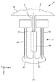
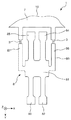
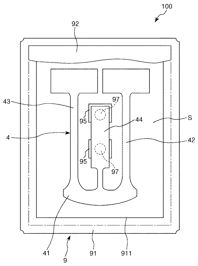
図24に示す振動子100は、前述した第1実施形態の振動片基板1から分離された振動片4と、振動片4を収容するパッケージ9と、を有している。パッケージ9は、上面に開口する凹部911を有する箱状のベース91と、凹部911の開口を塞いでベース91に接合された板状のリッド92と、を有している。パッケージ9は、凹部911の開口をリッド92で塞ぐことで形成された気密的な収容空間Sを有しており、この収容空間Sに振動片4が収容されている。なお、収容空間S内は、減圧(好ましくは真空)状態となっているのが好ましい。これにより、粘性抵抗を低減することができ、振動片4の振動特性が向上する。
A
また、図25に示すように、ベース91の凹部911の底面には2つの内部端子95が配置され、ベース91の底面には2つの外部端子96が配置されている。そして、対応する内部端子95と外部端子96とが、それぞれ、ベース91に配置された図示しない内部配線を介して電気的に接続されている。また、内部端子95上には、導電性接着材97が設けられており、この導電性接着材97を介して振動片4がベース91に固定されていると共に、内部端子95と電気的に接続されている。
Further, as shown in FIG. 25, two
このような振動子100によれば、所望の振動特性(共振周波数やCI値)からのずれが少ない振動片4を用いているため、高い信頼性が得られる。
According to such a
次に、このような振動子100で用いられる振動片4の製造方法について説明する。振動片4の製造方法は、図26に示すように、振動片基板1を準備する準備工程と、振動片4の振動特性を測定する測定工程と、折り取り部3を切断して振動片4を支持部2から分離する分離工程と、を含んでいる。
Next, a method for manufacturing the
準備工程では、まず、水晶ウエハ10を準備し、この水晶ウエハ10をフォトリソグラフィー技法およびエッチング技法を用いてパターニングすることで、支持部2、折り取り部3および振動体40を一体形成する。次に、蒸着法、スパッタリング法等によって水晶ウエハ10の表面に金属膜を成膜し、この金属膜をフォトリソグラフィー技法およびエッチング技法を用いてパターニングすることで電極を形成する。これにより、振動片4を保持する振動片基板1が得られる。
In the preparation step, first, the
測定工程では、振動片4の共振周波数やCI値を測定する。そして、これらの値が所望の条件から外れている振動片4があれば、その振動片4を除去する(または、後述する分離工程で分離されないように配置場所を記憶しておく)。なお、本工程では、所望の条件から外れている振動片4に対して、振動腕42、43の質量を増減等させることで共振周波数やCI値を調整し、これらの値を所望の条件内に収めるようにしてもよい。
In the measurement process, the resonance frequency and CI value of the
分離工程では、例えば、振動片4を支持部2に対してZ軸方向へ押圧することで折り取り部3が折れ、これにより、振動片4が支持部2から分離されて個片化される。以上により、振動片4が得られる。
In the separation step, for example, the
このような製造方法によれば、比較的簡単に、所望の振動特性(共振周波数やCI値)からのずれが少ない振動片4が得られる。
According to such a manufacturing method, it is relatively easy to obtain the
<第8実施形態>
次に、本発明の第8実施形態に係る発振器について説明する。
<Eighth Embodiment>
Next, an oscillator according to an eighth embodiment of the invention will be described.
図27は、本発明の第8実施形態に係る発振器を示す断面図である。
図27に示す発振器200は、振動片基板1から分離された振動片4と、振動片4と電気的に接続されているIC210と、振動片4およびIC210を収容するパッケージ9と、を有している。すなわち、発振器200は、前述した振動子100に、IC210を加えた構成となっている。IC210は、ベース91の凹部911の底面に固定され、内部端子95および外部端子96と電気的に接続されている。また、IC210は、発振回路211を有し、IC210からの駆動信号によって振動片4を駆動することで、所定の周波数の信号を取り出すことができるようになっている。
FIG. 27 is a sectional view showing an oscillator according to the eighth embodiment of the invention.
An
このような発振器200によれば、所望の振動特性(共振周波数やCI値)からのずれが少ない振動片4を用いているため、高い信頼性が得られる。
According to such an
[電子機器]
次に、本発明の電子機器を説明する。
[Electronics]
Next, the electronic apparatus of the present invention will be described.
図28は、本発明の電子機器を適用したモバイル型(またはノート型)のパーソナルコンピューターの構成を示す斜視図である。この図において、パーソナルコンピューター1100は、キーボード1102を備えた本体部1104と、表示部1108を備えた表示ユニット1106と、により構成され、表示ユニット1106は、本体部1104に対しヒンジ構造部を介して回動可能に支持されている。このようなパーソナルコンピューター1100には、例えば発振器の一部として用いられる振動片4が内蔵されている。
FIG. 28 is a perspective view showing the configuration of a mobile (or notebook) personal computer to which the electronic apparatus of the present invention is applied. In this figure, a
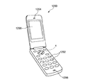
図29は、本発明の電子機器を適用した携帯電話機(スマートフォン、PHS等も含む)の構成を示す斜視図である。この図において、携帯電話機1200は、アンテナ(図示せず)、複数の操作ボタン1202、受話口1204および送話口1206を備え、操作ボタン1202と受話口1204との間には、表示部1208が配置されている。このような携帯電話機1200は、例えば発振器の一部として用いられる振動片4が内蔵されている。
FIG. 29 is a perspective view illustrating a configuration of a mobile phone (including a smartphone, a PHS, and the like) to which the electronic device of the invention is applied. In this figure, a
図30は、本発明の電子機器を適用したデジタルスチールカメラの構成を示す斜視図である。この図において、デジタルスチールカメラ1300におけるケース(ボディー)1302の背面には、表示部1310が設けられ、CCDによる撮像信号に基づいて表示を行う構成になっており、表示部1310は、被写体を電子画像として表示するファインダーとして機能する。また、ケース1302の正面側(図中裏面側)には、光学レンズ(撮像光学系)やCCDなどを含む受光ユニット1304が設けられている。そして、撮影者が表示部1310に表示された被写体像を確認し、シャッターボタン1306を押下すると、その時点におけるCCDの撮像信号が、メモリー1308に転送・格納される。このようなデジタルスチールカメラ1300は、例えば発振器の一部として用いられる振動片4が内蔵されている。
FIG. 30 is a perspective view showing a configuration of a digital still camera to which the electronic apparatus of the present invention is applied. In this figure, a
このような電子機器は、所望の振動特性(共振周波数やCI値)からのずれが少ない振動片4を有しているため、高精度で低消費電力であり、また、振動片4の歩留まりが高いことに起因して低価格である特徴を有している。
Since such an electronic device has the
なお、本発明の電子機器は、図28のパーソナルコンピューター、図29の携帯電話機、図30のデジタルスチールカメラの他にも、例えば、スマートフォン、タブレット端末、時計(スマートウォッチを含む)、インクジェット式吐出装置(例えばインクジェットプリンタ)、ラップトップ型パーソナルコンピューター、テレビ、HMD(ヘッドマウントディスプレイ)等のウェアラブル端末、ビデオカメラ、ビデオテープレコーダー、カーナビゲーション装置、ページャ、電子手帳(通信機能付も含む)、電子辞書、電卓、電子ゲーム機器、ワードプロセッサー、ワークステーション、テレビ電話、防犯用テレビモニター、電子双眼鏡、POS端末、医療機器(例えば電子体温計、血圧計、血糖計、心電図計測装置、超音波診断装置、電子内視鏡)、魚群探知機、各種測定機器、計器類(例えば、車両、航空機、船舶の計器類)、フライトシミュレーター等に適用することができる。 In addition to the personal computer of FIG. 28, the mobile phone of FIG. 29, and the digital still camera of FIG. 30, the electronic device of the present invention includes, for example, a smartphone, a tablet terminal, a watch (including a smart watch), an inkjet discharge Wearable terminals such as devices (for example, inkjet printers), laptop personal computers, televisions, HMDs (head-mounted displays), video cameras, video tape recorders, car navigation devices, pagers, electronic notebooks (including those with communication functions), electronic Dictionary, calculator, electronic game device, word processor, workstation, video phone, crime prevention TV monitor, electronic binoculars, POS terminal, medical device (eg electronic thermometer, blood pressure monitor, blood glucose meter, electrocardiogram measuring device, ultrasound diagnostic device, electronic Endoscope), a fish finder, various measurement devices, gauges (e.g., gages for vehicles, aircraft, and ships), can be applied to a flight simulator or the like.
[移動体]
次に、本発明の移動体を説明する。
[Moving object]
Next, the moving body of the present invention will be described.
図31は、本発明の移動体を適用した自動車を示す斜視図である。この図において、自動車1500には、例えば発振器の一部として用いられる振動片4が搭載されている。振動片4は、キーレスエントリー、イモビライザー、カーナビゲーションシステム、カーエアコン、アンチロックブレーキシステム(ABS)、エアバック、タイヤ・プレッシャー・モニタリング・システム(TPMS:Tire Pressure Monitoring System)、エンジンコントロール、ハイブリッド自動車や電気自動車の電池モニター、車体姿勢制御システム、等の電子制御ユニット(ECU:electronic control unit)に広く適用できる。
FIG. 31 is a perspective view showing an automobile to which the moving body of the present invention is applied. In this figure, an
このような移動体は、所望の振動特性(共振周波数やCI値)からのずれが少ない振動片4を有しているため、高精度、低消費電力、低価格の特徴を有している。
Since such a moving body has the
以上、本発明の振動片基板、振動片の製造方法、振動子、発振器、電子機器および移動体について、図示の実施形態に基づいて説明したが、本発明は、これに限定されるものではなく、各部の構成は、同様の機能を有する任意の構成のものに置換することができる。また、本発明に、他の任意の構成物が付加されていてもよい。また、前述した各実施形態を適宜組み合わせてもよい。 As described above, the resonator element substrate, the method for manufacturing the resonator element, the vibrator, the oscillator, the electronic device, and the moving body of the present invention have been described based on the illustrated embodiments, but the present invention is not limited to this. The configuration of each unit can be replaced with any configuration having the same function. In addition, any other component may be added to the present invention. Moreover, you may combine each embodiment mentioned above suitably.
また、前述した実施形態では、主振動がX軸逆相モードである振動片について説明したが、振動片の主振動としては、X軸逆相モードに限定されず、例えば、Z軸逆相モードであってもよい。主振動がZ軸逆相モードであると、振動腕の厚さ方向が屈曲振動方向となるため、振動腕の厚さを薄くすることによって容易に小型化することができる。 In the above-described embodiment, the vibration piece whose main vibration is the X-axis reverse phase mode has been described. However, the main vibration of the vibration piece is not limited to the X-axis reverse phase mode, for example, the Z-axis reverse phase mode. It may be. When the main vibration is in the Z-axis anti-phase mode, the thickness direction of the vibrating arm is the bending vibration direction, and thus the size can be easily reduced by reducing the thickness of the vibrating arm.
また、前述した実施形態では、振動片基板(振動体)を水晶で構成しているが、振動片基板の構成材料としては、水晶に限定されず、例えば、窒化アルミニウム(AlN)や、ニオブ酸リチウム(LiNbO3)、タンタル酸リチウム(LiTaO3)、チタン酸ジルコン酸鉛(PZT)、四ホウ酸リチウム(Li2B4O7)、ランガサイト(La3Ga5SiO14)、ニオブ酸カリウム(KNbO3)、リン酸ガリウム(GaPO4)、ガリウム砒素(GaAs)、窒化アルミニウム(AlN)、酸化亜鉛(ZnO、Zn2O3)、チタン酸バリウム(BaTiO3)、チタン酸鉛(PbPO3)、ニオブ酸ナトリウムカリウム((K,Na)NbO3)、ビスマスフェライト(BiFeO3)、ニオブ酸ナトリウム(NaNbO3)、チタン酸ビスマス(Bi4Ti3O12)、チタン酸ビスマスナトリウム(Na0.5Bi0.5TiO3)などの酸化物基板や、ガラス基板上に窒化アルミニウムや五酸化タンタル(Ta2O5)などの圧電体材料を積層させて構成された積層圧電基板、あるいは圧電セラミックスなどを用いることができる。 In the above-described embodiment, the resonator element substrate (vibrating body) is made of crystal. However, the constituent material of the resonator element substrate is not limited to crystal, and for example, aluminum nitride (AlN), niobic acid, and the like. Lithium (LiNbO 3 ), lithium tantalate (LiTaO 3 ), lead zirconate titanate (PZT), lithium tetraborate (Li 2 B 4 O 7 ), langasite (La 3 Ga 5 SiO 14 ), potassium niobate (KNbO 3 ), gallium phosphate (GaPO 4 ), gallium arsenide (GaAs), aluminum nitride (AlN), zinc oxide (ZnO, Zn 2 O 3 ), barium titanate (BaTiO 3 ), lead titanate (PbPO 3) ), potassium sodium niobate ((K, Na) NbO 3 ), bismuth ferrite (BiFeO 3), sodium niobate (NaNbO 3), bismuth titanate (Bi 4 Ti 3 O 12) , bismuth sodium titanate (Na 0.5 Bi 0.5 TiO 3) oxide substrate or the like, aluminum nitride on a glass substrate or a tantalum pentoxide A laminated piezoelectric substrate formed by laminating piezoelectric materials such as (Ta 2 O 5 ), piezoelectric ceramics, or the like can be used.
また、前述した実施形態では、水晶からなる振動基板に電極を配置することで振動片を構成しているが、振動片としては、これに限定されず、例えば、シリコン基板(シリコン単結晶(Si)、多結晶シリコン(ポリシリコン)、非晶質シリコン(アモルファスシリコン)のような非圧電体材からなる基板に、圧電素子(ピエゾ素子)を配置し、この圧電素子を伸縮させることによって、振動基板を振動させるような構成であってもよい。また、この他、静電気力を用いた静電駆動型や、磁力を用いたローレンツ駆動型などの振動片としてもよい。 In the above-described embodiment, the resonator element is configured by disposing an electrode on a resonator substrate made of quartz. However, the resonator element is not limited to this, for example, a silicon substrate (silicon single crystal (Si ), A piezoelectric element (piezo element) is placed on a substrate made of a non-piezoelectric material such as polycrystalline silicon (polysilicon) or amorphous silicon (amorphous silicon), and this piezoelectric element is expanded and contracted to vibrate. In addition to the above, a vibration piece such as an electrostatic drive type using electrostatic force or a Lorentz drive type using magnetic force may be used.
1…振動片基板、10…水晶ウエハ、2…支持部、21…端子、22…端子、3…折り取り部、31…溝部、4…振動片、40…振動体、41…基部、42…振動腕、421…腕部、422、423…溝部、429…広幅部、43…振動腕、431…腕部、432、433…溝部、439…広幅部、44…支持腕、481…第1駆動電極、482…第1駆動端子、491…第2駆動電極、492…第2駆動端子、6…振動片、60…振動体、61…基部、621、622…検出腕、631、632…連結腕、641、642、643、644…駆動腕、651、652…支持部、661、662、663、664…梁部、7…振動片、70…振動体、71…基部、72、73…振動腕、74…支持部、741、742…支持腕、743…連結部、8…振動片、80…振動体、81…基部、82、83…駆動腕、84、85…検出腕、86、87…支持腕、9…パッケージ、91…ベース、911…凹部、92…リッド、95…内部端子、96…外部端子、97…導電性接着材、100…振動子、200…発振器、210…IC、211…発振回路、1100…パーソナルコンピューター、1102…キーボード、1104…本体部、1106…表示ユニット、1108…表示部、1200…携帯電話機、1202…操作ボタン、1204…受話口、1206…送話口、1208…表示部、1300…デジタルスチールカメラ、1302…ケース、1304…受光ユニット、1306…シャッターボタン、1308…メモリー、1310…表示部、1500…自動車、A、B、C、D、E、F、G…矢印、F1…仮想振動対称面、F2…第1仮想振動対称面、F3…第2仮想振動対称面、S…収容空間、Sy…領域、ωy…角速度、ωz…角速度、K1、K2…曲線、L、L’…長さ、T…厚さ、W、W’、W”…幅
DESCRIPTION OF
Claims (17)
連結部と、
前記振動片に前記連結部を介して接続されている支持部と、
を有し、
前記振動片は、
基部と、
前記基部から第1方向に延びている振動腕と、
を有し、
nを2以上の自然数、
jを1以上であって前記n以下の自然数としたとき、
前記振動片は、互いに異なる共振周波数を有する前記n個の固有振動モードを有した振動をし、
前記n個の固有振動モードは、主振動の固有振動モードを含み、
前記n個の固有振動モードのそれぞれに対応する共振周波数fjと任意の整数kjとの関係において、
前記主振動の共振周波数をf1とし、規格化された周波数差Δfを
前記任意の整数kjは、
A connecting portion;
A support portion connected to the vibrating piece via the connecting portion;
Have
The vibrating piece is
The base,
A vibrating arm extending in a first direction from the base;
Have
n is a natural number of 2 or more,
When j is 1 or more and the natural number is n or less,
The vibrating piece vibrates having the n natural vibration modes having different resonance frequencies,
The n natural vibration modes include a natural vibration mode of a main vibration,
In the relationship between the resonance frequency f j corresponding to each of the n natural vibration modes and an arbitrary integer k j ,
The resonant frequency of the main vibration and f 1, the normalized frequency difference Δf
The arbitrary integer k j is
前記振動片は、
前記第1方向と交差する第2方向に並び、前記基部から前記第1方向に延びている一対の前記振動腕を有し、
前記一対の振動腕が前記第2方向に逆相で屈曲振動する第2方向逆相モード、
前記一対の振動腕が前記第2方向に同相で屈曲振動する第2方向同相モード、
前記一対の振動腕が前記基部の厚さ方向に沿う第3方向に逆相で屈曲振動する第3方向逆相モード、
前記一対の振動腕が前記第3方向に同相で屈曲振動する第3方向同相モード、
前記一対の振動腕がそれぞれの前記第1方向に延びる軸まわりに逆相で捩じれる捩り逆相モード、
前記一対の振動腕がそれぞれの前記第1方向に延びる軸まわりに同相で捩じれる捩り同相モード、
前記振動片基板が前記第3方向に沿って変形する第3方向基板モード、および
前記振動片基板の輪郭が前記第3方向と交差する方向に変形する基板輪郭モード、のうち、少なくとも2つの前記固有モードの高次モードを含んでいることを特徴とする振動片基板。 In claim 1 or 2,
The vibrating piece is
A pair of vibrating arms arranged in a second direction intersecting the first direction and extending from the base in the first direction;
A second direction anti-phase mode in which the pair of vibrating arms bend and vibrate in the opposite direction to the second direction;
A second direction in-phase mode in which the pair of vibrating arms flexurally vibrate in the second direction in phase;
A third direction anti-phase mode in which the pair of vibrating arms bend and vibrate in a reverse phase in a third direction along the thickness direction of the base,
A third direction in-phase mode in which the pair of vibrating arms bend and vibrate in phase in the third direction;
A torsional anti-phase mode in which the pair of vibrating arms is twisted in an anti-phase around an axis extending in the first direction;
A torsional in-phase mode in which the pair of vibrating arms are twisted in-phase around an axis extending in the first direction;
At least two of the third direction substrate mode in which the resonator element substrate deforms along the third direction and the substrate contour mode in which the contour of the resonator element substrate deforms in a direction intersecting the third direction. A vibrating piece substrate comprising a higher-order mode of an eigenmode.
前記第3方向基板モードおよび前記基板輪郭モードの高次モードは、2次以上、10次以下のモードであることを特徴とする振動片基板。 In claim 3,
The high-order mode of the third direction substrate mode and the substrate contour mode is a second-order or higher-order or lower-order mode, wherein the resonator element substrate is characterized in that:
前記主振動は、前記第2方向逆相モードであることを特徴とする振動片基板。 In claim 3 or 4,
The vibration piece substrate according to claim 1, wherein the main vibration is the second direction anti-phase mode.
前記振動腕は、主面に開口する溝部を有し、
前記振動腕の前記第1方向の長さをL[m]としたとき、
前記振動腕の基端と前記基端から先端側へL/3離間した位置との間に少なくとも前記溝部の一部が設けられており、
前記振動腕の前記主振動の振動方向の長さをW[m]としたとき、
ただし、
Cp[J/(kg・K)]は、前記振動腕の熱容量
k[W/(m・K)]は、前記振動腕の前記主振動の振動方向に沿った熱伝導率 In claim 5,
The resonating arm has a groove that opens in a main surface,
When the length of the vibrating arm in the first direction is L [m],
At least a part of the groove is provided between the base end of the vibrating arm and a position spaced from the base end to the tip side by L / 3,
When the length of the vibration direction of the main vibration of the vibrating arm is W [m],
However,
前記振動腕の前記主振動の振動方向の長さをW[m]としたとき、
ただし、
Cp[J/(kg・K)]は、前記振動腕の熱容量
k[W/(m・K)]は、前記振動腕の前記主振動の振動方向に沿った熱伝導率 In claim 5,
When the length of the vibration direction of the main vibration of the vibrating arm is W [m],
However,
前記振動片は、前記主振動に対して対称面となる1つの仮想振動対称面を有していることを特徴とする振動片基板。 In any one of Claims 5 thru | or 7,
The vibration piece substrate has one virtual vibration symmetry plane which is a symmetry plane with respect to the main vibration.
前記振動片は、前記主振動に対して対称面となる仮想振動対称面を少なくとも2つ有していることを特徴とする振動片基板。 In any one of Claims 5 thru | or 7,
The vibration piece substrate has at least two virtual vibration symmetry planes that are symmetrical with respect to the main vibration.
前記連結部は、前記仮想振動対称面と重なっていることを特徴とする振動片基板。 In any one of Claims 5 thru | or 9,
The connecting piece overlaps with the virtual vibration symmetry plane.
前記連結部は、前記仮想振動対称面から離間していることを特徴とする振動片基板。 In any one of Claims 5 thru | or 9,
The connecting part is spaced apart from the virtual vibration symmetry plane.
前記振動片のQ値をQとしたとき、
ただし、
B=1.2544×10⁻⁵
C=1.1以上、1.3以下
ρ[kg/m3]は、前記振動腕の質量密度
Cp[J/(kg・K)]は、前記振動腕の熱容量
c[N/m2]は、前記振動腕の延在方向に関する弾性定数
α[1/K]は、前記振動腕の延びる方向に関する熱膨張係数
Θ[K]は、環境温度
k[W/(m・K)]は、前記振動腕の前記主振動の振動方向に沿った熱伝導率
πは、円周率 In any one of Claims 1 thru | or 11,
When the Q value of the resonator element is Q,
However,
B = 1.2544 × 10 −5
C = 1.1 or more and 1.3 or less ρ [kg / m 3 ] is the mass density of the vibrating arm Cp [J / (kg · K)] is the heat capacity of the vibrating arm c [N / m 2 ] Is the elastic constant α [1 / K] in the extending direction of the vibrating arm, the thermal expansion coefficient Θ [K] in the extending direction of the vibrating arm is the environmental temperature k [W / (m · K)], The thermal conductivity π along the vibration direction of the main vibration of the vibrating arm π is the circumference ratio
前記連結部を切断して前記振動片を前記支持部から分離する工程と、を含んでいることを特徴とする振動片の製造方法。 A step of preparing the resonator element substrate according to any one of claims 1 to 12,
Cutting the connecting portion to separate the vibrating piece from the support portion.
前記振動片を収容するパッケージと、を有していることを特徴とする振動子。 The vibration piece separated from the vibration piece substrate according to any one of claims 1 to 12,
And a package for housing the resonator element.
発振回路と、を有していることを特徴とする発振器。 The vibration piece separated from the vibration piece substrate according to any one of claims 1 to 12,
And an oscillator circuit.
Priority Applications (1)
| Application Number | Priority Date | Filing Date | Title |
|---|---|---|---|
| JP2016088409A JP2017200014A (en) | 2016-04-26 | 2016-04-26 | Vibration piece substrate, manufacturing method for vibration piece, vibrator, oscillator, electronic apparatus, and movable body |
Applications Claiming Priority (1)
| Application Number | Priority Date | Filing Date | Title |
|---|---|---|---|
| JP2016088409A JP2017200014A (en) | 2016-04-26 | 2016-04-26 | Vibration piece substrate, manufacturing method for vibration piece, vibrator, oscillator, electronic apparatus, and movable body |
Publications (1)
| Publication Number | Publication Date |
|---|---|
| JP2017200014A true JP2017200014A (en) | 2017-11-02 |
Family
ID=60239586
Family Applications (1)
| Application Number | Title | Priority Date | Filing Date |
|---|---|---|---|
| JP2016088409A Pending JP2017200014A (en) | 2016-04-26 | 2016-04-26 | Vibration piece substrate, manufacturing method for vibration piece, vibrator, oscillator, electronic apparatus, and movable body |
Country Status (1)
| Country | Link |
|---|---|
| JP (1) | JP2017200014A (en) |
Cited By (2)
| Publication number | Priority date | Publication date | Assignee | Title |
|---|---|---|---|---|
| CN109842394A (en) * | 2017-11-28 | 2019-06-04 | 精工爱普生株式会社 | Vibration device, the manufacturing method of vibration device, electronic equipment and moving body |
| JP2019174254A (en) * | 2018-03-28 | 2019-10-10 | リバーエレテック株式会社 | AE sensor element and AE sensor |
-
2016
- 2016-04-26 JP JP2016088409A patent/JP2017200014A/en active Pending
Cited By (4)
| Publication number | Priority date | Publication date | Assignee | Title |
|---|---|---|---|---|
| CN109842394A (en) * | 2017-11-28 | 2019-06-04 | 精工爱普生株式会社 | Vibration device, the manufacturing method of vibration device, electronic equipment and moving body |
| CN109842394B (en) * | 2017-11-28 | 2023-06-30 | 精工爱普生株式会社 | Vibration device, method for manufacturing vibration device, electronic apparatus, and moving object |
| JP2019174254A (en) * | 2018-03-28 | 2019-10-10 | リバーエレテック株式会社 | AE sensor element and AE sensor |
| JP7030331B2 (en) | 2018-03-28 | 2022-03-07 | リバーエレテック株式会社 | AE sensor element and AE sensor |
Similar Documents
| Publication | Publication Date | Title |
|---|---|---|
| JP6107333B2 (en) | Vibrator, oscillator, electronic device, and moving object | |
| US10659006B2 (en) | Resonator element, resonator, electronic device, electronic apparatus, and moving object | |
| US20140292433A1 (en) | Resonator element, resonator, oscillator, electronic apparatus, and moving object | |
| CN108183698B (en) | Resonator element, resonator, oscillator, electronic apparatus, sensor, and moving object | |
| JP2015226242A (en) | Electronic device, electronic apparatus, and movable body | |
| TWI649964B (en) | Vibrating element, vibrator, oscillator, electronic device, and moving object | |
| US9654082B2 (en) | Vibrator, oscillator, electronic device for controlling internal resonance between inherent vibration modes | |
| JP2016086383A (en) | Vibration element, electronic device, electronic equipment and mobile body | |
| CN108631749B (en) | Vibration device, oscillator, gyro sensor, electronic apparatus, and moving body | |
| US10326427B2 (en) | Resonator, oscillator, electronic apparatus, and vehicle | |
| JP6287208B2 (en) | Vibrators, oscillators, electronic devices, physical quantity sensors, and moving objects | |
| JP2015097366A (en) | Vibration element, vibrator, oscillator, electronic device and mobile object | |
| JP2017200014A (en) | Vibration piece substrate, manufacturing method for vibration piece, vibrator, oscillator, electronic apparatus, and movable body | |
| JP2014200050A (en) | Vibration element, vibrator, oscillator, electronic device, and mobile unit | |
| JP6884981B2 (en) | Oscillators, oscillators, real-time clocks, electronics and mobiles | |
| JP2015149591A (en) | Oscillation element, transducer, oscillator, electronic apparatus, sensor and mobile object | |
| JP2015149592A (en) | Vibration element, vibrator, oscillator, electronic device, and mobile unit | |
| US20140368287A1 (en) | Resonator element, resonator, oscillator, electronic device, and moving object | |
| JP2018093553A (en) | Electronic device, electronic apparatus, and movable body | |
| JP2019009619A (en) | Vibration element, vibrator, generator, electronic apparatus, and mobile body | |
| JP6488861B2 (en) | Vibrating piece, vibrator, oscillator, real-time clock, sensor, electronic device and moving object | |
| JP2016017768A (en) | Sensor element, sensor device, electronic equipment and mobile object | |
| JP2015097368A (en) | Vibrator, oscillator, electronic apparatus and movable body | |
| JP6465152B2 (en) | Vibrating piece, vibrator, electronic device, electronic device, and moving object | |
| JP2018061286A (en) | Vibration element, vibrator, oscillator, electronic apparatus, and movable body |