JP2017199466A - Electric connector - Google Patents
Electric connector Download PDFInfo
- Publication number
- JP2017199466A JP2017199466A JP2016087201A JP2016087201A JP2017199466A JP 2017199466 A JP2017199466 A JP 2017199466A JP 2016087201 A JP2016087201 A JP 2016087201A JP 2016087201 A JP2016087201 A JP 2016087201A JP 2017199466 A JP2017199466 A JP 2017199466A
- Authority
- JP
- Japan
- Prior art keywords
- connector
- fitting
- holding member
- mating
- state
- Prior art date
- Legal status (The legal status is an assumption and is not a legal conclusion. Google has not performed a legal analysis and makes no representation as to the accuracy of the status listed.)
- Pending
Links
Images


Abstract
Description
本発明は、相手コネクタとの嵌合状態を嵌合保持部材により保持する構成を備えた電気コネクタに関する。 The present invention relates to an electrical connector having a configuration in which a fitting state with a mating connector is held by a fitting holding member.
一般に、各種電気機器等において、種々の信号伝送媒体を通して送られる電気信号を、配線基板上に実装された電気コネクタを介して配線基板上の電子回路に伝送することが広く行われている。より具体的には、同軸ケーブルや、フレキシブル・プリンテッド・サーキット(FPC)又はフレキシブル・フラット・ケーブル(FFC)等の信号伝送媒体の端末部分が連結された相手コネクタが、配線基板上に実装された電気コネクタの挿入開口部から内方側の嵌合空間に向かって挿入されていき、信号伝送媒体の端末部分が、コンタクト部材を介して又は直接的に、電気コネクタの内部に配置されたコンタクト部材に接触するように嵌合状態になされることで信号回路が形成されるようになっている。 In general, in various electric devices and the like, it is widely performed to transmit an electric signal sent through various signal transmission media to an electronic circuit on a wiring board via an electric connector mounted on the wiring board. More specifically, a mating connector to which a terminal portion of a signal transmission medium such as a coaxial cable, a flexible printed circuit (FPC), or a flexible flat cable (FFC) is connected is mounted on a wiring board. The contact is inserted from the insertion opening of the electrical connector toward the inward fitting space, and the terminal portion of the signal transmission medium is disposed inside the electrical connector via the contact member or directly. A signal circuit is formed by being in a fitted state so as to contact the member.
このように各種の信号伝送媒体の端末部分が連結された相手コネクタが嵌合状態になされると、その相手コネクタの嵌合状態を維持するために、相手コネクタに回動可能に取り付けられた嵌合保持部材(プルバー)の回動操作が行われ、その嵌合保持部材の一部を電気コネクタの本体部に係合させることで相手コネクタの脱落等を防止する構成が、従来からしばしば採用されている。 In this way, when the mating connector to which the terminal portions of various signal transmission media are connected is brought into the fitted state, the fitting attached to the mating connector is rotatably attached in order to maintain the mated state of the mating connector. Conventionally, a configuration in which the mating holding member (pull bar) is rotated and a part of the fitting holding member is engaged with the main body of the electrical connector to prevent the mating connector from falling off is often employed. ing.
例えば、下記の先行文献1(特開2013−041680号公報)においては、配線基板上に実装されたリセプタクルコネクタに対してプラグコネクタ(相手コネクタ)が嵌合状態とされた後に、プラグコネクタに設けられた嵌合保持部材(プルバー)が、待機位置から作用位置まで回動操作され、その嵌合保持部材の端縁部分がリセプタクルコネクタの一部に係合される。そして、その作用位置に回動された嵌合保持部材を介して、配線基板に固定されているリセプタクルコネクタに、相手コネクタであるプラグコネクタが連結された状態になされ、両電気コネクタ同士が脱落不可能な状態に保持されるようになっている。 For example, in the following prior art document 1 (Japanese Patent Laid-Open No. 2013-041680), a plug connector (mating connector) is fitted to a receptacle connector mounted on a wiring board, and then provided on the plug connector. The fitted holding member (pull bar) is rotated from the standby position to the operating position, and the edge portion of the fitted holding member is engaged with a part of the receptacle connector. Then, the plug connector, which is the mating connector, is connected to the receptacle connector fixed to the wiring board via the fitting holding member rotated to the operating position, and the two electrical connectors are not dropped off. It is held in a possible state.
ここで、上述したようにリセプタクルコネクタは、配線基板によって強固な固定状態になされているが、プラグコネクタは、リセプタクルコネクタとの嵌合部分を介在して保持状態になされているため、その嵌合部分に生じる隙間や製造誤差の分だけガタ付を有する状態になっている。従って、従来の電気コネクタ装置のように、プラグコネクタ(相手コネクタ)に嵌合保持部材(プルバー)が取り付けられていると、嵌合保持部材の部品精度や、その取付け精度、及び係合の精度を向上させたとしても、上述した嵌合部分のガタ付から両電気コネクタ同士の嵌合状態が安定化しないおそれがある。一方、両電気コネクタ同士の嵌合状態を安定化させるべく、両電気コネクタが嵌合している部分の長さを増大させた構成も従来から採用されているが、その場合にあっては、電気コネクタ装置の全体が大型化する傾向となってしまい、近年の小型化の要請に対応できなくなることもある。 Here, as described above, the receptacle connector is firmly fixed by the wiring board, but since the plug connector is held by interposing a fitting portion with the receptacle connector, the fitting is performed. It is in a state having a backlash corresponding to a gap generated in the portion and a manufacturing error. Therefore, when the fitting holding member (pull bar) is attached to the plug connector (mating connector) as in the conventional electrical connector device, the component accuracy of the fitting holding member, its mounting accuracy, and the engagement accuracy Even if it improves, there exists a possibility that the fitting state of both electrical connectors may not be stabilized from the backlash of the fitting part mentioned above. On the other hand, in order to stabilize the fitting state between the two electrical connectors, a configuration in which the length of the portion in which the two electrical connectors are fitted is also conventionally employed, but in that case, The entire electrical connector device tends to be enlarged, and may not be able to meet the recent demand for miniaturization.
そこで本発明は、簡易な構成で、両電気コネクタ同士の嵌合状態を安定的に維持することができるようにした電気コネクタを提供することを目的とする。 SUMMARY OF THE INVENTION An object of the present invention is to provide an electrical connector having a simple configuration and capable of stably maintaining a fitting state between both electrical connectors.
上記目的を達成するため請求項1にかかる発明においては、配線基板に実装された状態のコネクタ本体部に相手コネクタが嵌合されるものであって、待機位置から作用位置まで回動操作された嵌合保持部材により前記相手コネクタが嵌合状態に維持される構成になされた電気コネクタにおいて、前記嵌合保持部材は、前記コネクタ本体部に回動可能に設けられ、前記作用位置に回動操作されたときに前記相手コネクタに対して係合した状態に維持される構成が採用されている。
In order to achieve the above object, in the invention according to
このような構成を備えた請求項1にかかる発明によれば、配線基板に実装されて固定状態になされるコネクタ本体部に嵌合保持部材が取り付けられていることから、当該嵌合保持部材が配線基板により安定的に保持された状態となり、その安定的に保持された嵌合保持部材を介して相手コネクタの嵌合状態が良好に維持されるようになっている。 According to the first aspect of the invention having such a configuration, since the fitting holding member is attached to the connector main body portion that is mounted on the wiring board and fixed, the fitting holding member is The state is stably held by the wiring board, and the mating state of the mating connector is favorably maintained through the stably holding fitting holding member.
このとき、請求項2にかかる発明のように、前記嵌合保持部材が、板状又は棒状の形状を有している構成とすることが可能である。
At this time, as in the invention according to
また、請求項3にかかる発明のように、前記嵌合保持部材が、当該嵌合保持部材の回動半径方向において前記相手コネクタの最外郭面に係合される構成になされていることが望ましい。 Further, as in the invention according to claim 3, it is desirable that the fitting holding member is configured to be engaged with the outermost surface of the mating connector in the turning radius direction of the fitting holding member. .
このような構成を備えた請求項3にかかる発明によれば、相手コネクタに対する嵌合保持部材の係合力が安定的に得られる。 According to the invention concerning Claim 3 provided with such a structure, the engaging force of the fitting holding member with respect to the other connector can be obtained stably.
ここで、請求項4にかかる発明のように、前記相手コネクタの最外郭面は、当該相手コネクタの嵌合方向に対して略直交する面であることが望ましい。 Here, as in the invention according to claim 4, it is desirable that the outermost surface of the mating connector is a surface substantially orthogonal to the fitting direction of the mating connector.
このような構成を備えた請求項4にかかる発明によれば、相手コネクタの嵌合方向に対して略直交した状態で嵌合保持部材が前記相手コネクタの最外郭面に係合されるので、相手コネクタに対する嵌合保持部材の係合力が、さらに安定的に得られる。 According to the invention according to claim 4 having such a configuration, since the fitting holding member is engaged with the outermost surface of the mating connector in a state substantially orthogonal to the mating direction of the mating connector, The engagement force of the fitting holding member with respect to the mating connector can be obtained more stably.
一方、請求項5にかかる発明のように、絶縁ハウジングを覆う導電性シェルが、前記配線基板に接続される基板接続部を備えたものであって、前記嵌合保持部材は、前記導電性シェルの前記基板接続部の近傍に回動可能に取り付けられていることが望ましい。 On the other hand, as in the invention according to claim 5, the conductive shell covering the insulating housing is provided with a board connecting portion connected to the wiring board, and the fitting holding member is the conductive shell. It is desirable that it is pivotally attached in the vicinity of the board connecting portion.
このような構成を備えた請求項5記載の発明によれば、配線基板に固定された部分に対して嵌合保持部材が直接的に取り付けられていることから、嵌合保持部材の保持が確実に行われ、相手コネクタとの嵌合状態が、一層高められる。 According to the invention of claim 5 having such a configuration, since the fitting holding member is directly attached to the portion fixed to the wiring board, the fitting holding member is reliably held. The fitting state with the mating connector is further enhanced.
また、請求項6にかかる発明のように、請求項1乃至5のいずれかに記載の電気コネクタと、当該電気コネクタに嵌合される相手コネクタとを備えた構成を採用すれば、電気コネクタ装置においても、上述した作用が同様に得られる。
Moreover, if the structure provided with the electrical connector according to any one of
以上のように本発明は、配線基板に実装された状態のコネクタ本体部に、待機位置から作用位置まで回動操作される嵌合保持部材を設け、作用位置に回動操作された嵌合保持部材を相手コネクタに係合させた状態に維持し、配線基板に実装される電気コネクタに嵌合保持部材を取り付けたことで嵌合保持部材を配線基板により安定的に保持し、その安定的に保持した嵌合保持部材を介して相手コネクタの嵌合状態を良好に維持させる構成を採用したことから、簡易な構成で、両電気コネクタ同士の嵌合状態を安定的に維持することができる。 As described above, according to the present invention, the connector main body mounted on the wiring board is provided with the fitting holding member that is rotated from the standby position to the operating position, and the fitting holding that is rotated to the operating position. The member is kept engaged with the mating connector, and the fitting holding member is attached to the electrical connector mounted on the wiring board so that the fitting holding member is stably held by the wiring board. Since the configuration for satisfactorily maintaining the mating state of the mating connector through the retained mating holding member is employed, the mating state between the two electrical connectors can be stably maintained with a simple configuration.
以下、複数本の同軸ケーブルを印刷配線基板側に接続する電気コネクタに本発明を適用した場合の実施形態に関する説明を図面に基づいて詳細に行う。 Hereinafter, an embodiment relating to an embodiment in which the present invention is applied to an electrical connector for connecting a plurality of coaxial cables to the printed wiring board side will be described in detail with reference to the drawings.
[電気コネクタ装置の全体構造の概要]
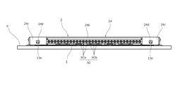
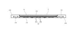
まず、図1〜図4に表された本発明の一実施形態にかかる電気コネクタ装置は、信号伝送媒体を構成する同軸ケーブルSCの端末部分が連結された相手コネクタとしてのプラグコネクタ1と、印刷配線基板P(図1,図21及び図22参照)上に実装された本発明の一実施形態にかかるリセプタクルコネクタ2とを備えた水平嵌合型の電気コネクタ装置であって、印刷配線基板P上に実装されたリセプタクルコネクタ2に対して、プラグコネクタ(相手コネクタ)1が略水平方向に対向するように配置された状態から、印刷配線基板Pの実装表面に略平行な方向(印刷配線基板Pの延在方向)にプラグコネクタ1がリセプタクルコネクタ2側に近接するように水平に移動される。それによって、プラグコネクタ1に設けられた横長状の電極部分が、リセプタクルコネクタ2に同じく横長状をなすように設けられた挿入開口部を通して差し込まれ(図21,22参照)、両電気コネクタ1,2同士が嵌合状態になされる。
[Overview of overall structure of electrical connector device]
First, an electrical connector device according to an embodiment of the present invention shown in FIGS. 1 to 4 includes a
このように本実施形態においては、相手コネクタとしてのプラグコネクタ1をリセプタクルコネクタ2に差し込む方向、およびその反対方向に抜き出す方向が、印刷配線基板Pの実装表面が延在する方向と略平行な方向となる構成になされているが、以下において、印刷配線基板Pの実装表面の延在方向を「水平方向」とし、印刷配線基板Pの実装表面に対して垂直なる方向を「上下方向」とする。
Thus, in the present embodiment, the direction in which the
そして、プラグコネクタ(相手コネクタ)1の単体においては、当該プラグコネクタ1をリセプタクルコネクタ2に差し込む方向を「前方向」、その反対方向に抜き出す方向を「後方向」とし、プラグコネクタ1の差し込み側の先端部分を「前端部分」、その反対側に対向する他端部分を「後端部分」とする。さらに、リセプタクルコネクタ2においては、当該リセプタクルコネクタ2からプラグコネクタ1を抜き出す方向を「前方向」、その反対方向を「後方向」とし、相手コネクタとしてのプラグコネクタ1が差し込まれる挿入開口部が設けられた「前端面」を含む側の端部分を「前端部分」、その反対側に対向する「後端面」を含む部分を「後端部分」とする。
In a single plug connector (mating connector) 1, the direction in which the
また、このような電気コネクタ装置を構成しているプラグコネクタ(相手コネクタ)1およびリセプタクルコネクタ2の両電気コネクタは、横長状に形成された樹脂等の絶縁部材からなるコネクタ本体部としての絶縁ハウジング11,21をそれぞれ備えているが、以下においては、これら絶縁ハウジング11,21の長手方向(図2の左右方向)を「コネクタ長手方向」と呼ぶこととする。
In addition, the plug connector (mating connector) 1 and the
上述した絶縁ハウジング11,21には、コネクタ長手方向(図2の左右方向)に沿って、同一形状を有する複数体の導電コンタクト部材(導電端子)12,22が、適宜のピッチ間隔で多極状をなすように配列されている。
In the insulating
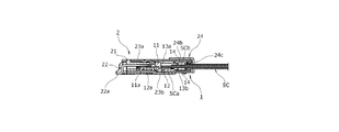
一方、両電気コネクタ1,2のうち、プラグコネクタ(相手コネクタ)1の後端部分には、特に図5〜図8に示されているように、コネクタ長手方向に沿って多極状に並列するように配列された複数本の同軸ケーブルSCの端末部分が連結されている。これらの各同軸ケーブルSCは、コネクタ長手方向における配置位置が、上述した導電コンタクト部材12に対応して設定されており、当該各同軸ケーブルSCの端末部分においては、被覆材が皮剥きされることによってケーブル中心導体(信号線)SCa及びケーブル外部導体(シールド線)SCbが同軸状をなすように露出されている。そして、その同軸ケーブルSCの中心軸線に沿って延在するように配置されたケーブル中心導体SCaが、信号伝送用の導電コンタクト部材12に接続されることによって信号回路が構成される。
On the other hand, among the
また、上述したケーブル中心導体SCaの外周側を同心状に取り囲むように配置されたケーブル外部導体SCbは、コネクタ長手方向に延在する導電性のグランド部材からなるグランドバー14にコモン接続されている。このグランドバー14は、上述した同軸ケーブルSCの多極配列方向(コネクタ長手方向)に沿って長尺状に延在する細長の帯板状部材またはブロック状部材から形成されており、当該グランドバー14が、同軸ケーブルSCのケーブル外部導体(シールド線)SCbに対して、半田付けやカシメや圧接等により一括的に接続されている。このようにして設けられたグランドバー14は、後述するリセプタクルコネクタ2の導電性シェル等を介して印刷配線基板Pに形成されたグランド回路に電気的に接続される。
Further, the cable outer conductor SCb disposed so as to concentrically surround the outer peripheral side of the cable center conductor SCa described above is commonly connected to the
[プラグコネクタの絶縁ハウジングおよび導電コンタクト部材について]
ここで、プラグコネクタ(相手コネクタ)1側に設けられた絶縁ハウジング11は、特に図5〜図8に示されている様に当該絶縁ハウジング11の本体部から前方側に向かって延出する平板状の嵌合突部11aを一体的に備えており、絶縁ハウジング11の本体部から嵌合突部11aにかけての上面側に、導電コンタクト部材(プラグ側コンタクト部材)12がインサート成形により埋設され、または圧入により保持されている。この導電コンタクト部材12は、絶縁ハウジング11の上側表面から上方に露出するようにして略水平に延在している。
[Insulation housing and conductive contact member of plug connector]
Here, the insulating
このようなプラグコネクタ(相手コネクタ)1に設けられた導電コンタクト部材(プラグ側コンタクト部材)12の後端部分には、上述した同軸ケーブルSCにおけるケーブル中心導体(信号線)SCaの端末部分が、上方側から当接された状態で半田接続されている。このときのケーブル中心導体SCaと導電コンタクト部材12との半田接合は、多極配列方向の複数箇所に対して一括的に行うことが可能であるが、そのような一括半田接合によって複数本の同軸ケーブルSCが効率的に連結される。
At the rear end portion of the conductive contact member (plug-side contact member) 12 provided in such a plug connector (mating connector) 1 is the terminal portion of the cable center conductor (signal line) SCa in the coaxial cable SC described above. Solder connection is made in a state of being in contact from above. At this time, the solder bonding between the cable center conductor SCa and the
一方、前述したように絶縁ハウジング(コネクタ本体部)11の前端部分に設けられた嵌合突部11aの上側表面には、導電コンタクト部材(プラグ側コンタクト部材)12の前方側部分を構成している端子電極部12aが、多極状の露出電極を形成するように配置されている。そして、この導電コンタクト部材12の前方側部分を構成している端子電極部12aは、前述したようにプラグコネクタ1がリセプタクルコネクタ2に嵌合されたときに、リセプタクルコネクタ2に設けられた導電コンタクト部材(リセ側コンタクト部材)22(例えば図5参照)に対して下方側から当接し、それによって信号伝送回路が形成される構成になされている。なお、これらの複数の導電コンタクト部材12,22のうちの一部を、グランド接続用として構成することも可能である。
On the other hand, as described above, the front surface portion of the conductive contact member (plug side contact member) 12 is formed on the upper surface of the
[リセプタクルコネクタの絶縁ハウジングおよび導電コンタクト部材について]
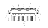
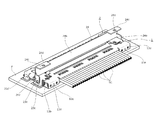
一方、図9〜図16に示されたリセプタクルコネクタ2側の絶縁ハウジング(コネクタ本体部)21の前方側部分には、コネクタ長手方向に沿って横長状に延在する挿入開口部21aが形成されているとともに、その挿入開口部21aから後方側に向かって延びる嵌合空間が同じく横長状をなすように形成されている。そして、上述したように相手コネクタとしてのプラグコネクタ1の嵌合突部11a(例えば図6参照)が、リセプタクルコネクタ2側の挿入開口部21aを通して嵌合空間の内部に挿入されて収容されるようになっている。
[Insulation housing and conductive contact member of receptacle connector]
On the other hand, an
また、リセプタクルコネクタ2側の絶縁ハウジング(コネクタ本体部)21に取り付けられた導電コンタクト部材(リセ側コンタクト部材)22は、上述したプラグコネクタ1側の導電コンタクト部材(プラグ側コンタクト部材)12に対応した位置に配置されている。このリセプタクルコネクタ2の絶縁ハウジング21に取り付けられた導電コンタクト部材22は、両電気コネクタ1,2同士の嵌合時に、プラグコネクタ1側の導電コンタクト部材12の端子電極部12aに対して上方側から弾性的に接触して電気的な接続状態になされる。
The conductive contact member (reset side contact member) 22 attached to the insulating housing (connector body) 21 on the
このような各導電コンタクト部材(リセ側コンタクト部材)22の後端部分には、例えば図11に示す様に印刷配線基板Pの実装表面(上側表面)に沿って延在するように形成された基板接続脚部22aが形成されており、その基板接続脚部22aが、実際の使用時(実装時)に、前述した印刷配線基板P上の信号導電路またはグランド接続用の導電路に載置された状態で、例えば一括的な半田接合が行われる。
For example, as shown in FIG. 11, the conductive contact member (reset side contact member) 22 is formed so as to extend along the mounting surface (upper surface) of the printed wiring board P. A
また、本実施形態における導電コンタクト部材(リセ側コンタクト部材)22は、上述した後端側の基板接続脚部22aから上方に折れ曲がった後に、前方側に向かって片持ち状に延出する構成になされており、その前方側への片持ち状の延出部分が弾性ビーム部になされている。このような導電コンタクト部材(リセ側コンタクト部材)22の基端部分を構成している固定基部は、絶縁ハウジング11の後端部分に対して圧入またはインサート成形されることで固定状態に保持されており、その固定基部の後方側に、上述した基板接続脚部22aが連設されているとともに、当該固定基部の前方側に、上述した弾性ビーム部が連設されている。
In addition, the conductive contact member (reset side contact member) 22 according to the present embodiment is configured to extend in a cantilevered manner toward the front side after being bent upward from the board
その導電コンタクト部材(リセ側コンタクト部材)22の弾性ビーム部は、絶縁ハウジング21に設けられた嵌合空間の内部において上下方向に弾性変位可能な状態に配置されており、当該弾性ビーム部における前方側の先端部分には、下方側に向かって山形状に張り出す接点凸部がそれぞれ設けられている。この導電コンタクト部材22の弾性ビーム部に設けられた接点凸部の下方側頂部は、プラグコネクタ1がリセプタクルコネクタ2に嵌合されたときに、プラグコネクタ1側の導電コンタクト部材(プラグ側コンタクト部材)12の端子電極部12aに対して、上方側から弾性的に押圧する状態で接触される構成になされており、このような弾性的な接触関係によって、上述した両接点部同士の電気的な接続が維持されるようになっている。
The elastic beam portion of the conductive contact member (reset side contact member) 22 is arranged in a state in which it can be elastically displaced in the vertical direction inside the fitting space provided in the insulating
[導電性シェルについて]
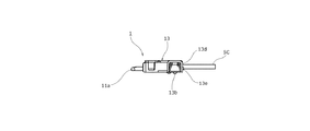
一方、プラグコネクタ1およびリセプタクルコネクタ2に設けられた各絶縁ハウジング11,21の外表面は、導電性の薄板状の金属部材を適宜の形状に折曲形成したプラグ側導電性シェル13およびリセ側導電性シェル23によりそれぞれ覆われている。これらプラグ側導電性シェル13およびリセ側導電性シェル23は、上述した絶縁ハウジング11,21と同様に「コネクタ本体部」を構成するものであって、各電気コネクタ1,2の内部に形成される信号伝送回路およびグランド回路を外方側から覆うことにより電磁遮蔽を行うシールド部材として装着されたものであるが、グランド回路の一部を構成する部材でもある。
[Conductive shell]
On the other hand, the outer surface of each of the insulating
[プラグ側導電性シェルについて]
そのうち、プラグコネクタ1側に装着されているプラグ側導電性シェル(コネクタ本体部)13は、特に図5〜図8に示されている様に絶縁ハウジング11を上下方向から挟む一対の上下シェル板13a,13bの嵌合体から構成されている。これらの上シェル板13a及び下シェル板13bをプラグコネクタ1に装着するにあたっては、その前工程として、まず同軸ケーブルSCの端末部分に対してグランドバー(グランド部材)14が半田接合された状態になされる。そして、上述したプラグ側導電性シェル13の下半側部分を構成する下シェル板13bが絶縁ハウジング11に対して下方側から被せられ、その下シェル板13bを被せられた絶縁ハウジング11の表面に、上述したグランドバー14を半田接合された状態の同軸ケーブルSCの端末部分が載置されるようにしてセットされ、その後に、プラグ側導電性シェル13の上半側部分を構成する上シェル板13aが、絶縁ハウジング11に対して上方側から被せるようにして装着されている。
[About the plug-side conductive shell]
Among them, the plug-side conductive shell (connector body portion) 13 mounted on the
このようなプラグ側導電性シェル13の下半側部分を構成している下シェル板13bには、多極配列方向(コネクタ長手方向)に沿って複数体のグランド接続舌片13c(図5参照)が、切り欠き加工によって形成されている。それらの各グランド接続舌片13cは、コネクタ内方側の空間に向かって突出する片持ちの板バネ状をなすように切り起こされており、前述したグランドバー14の下面側に対して弾性的に接触または半田接合されている。そして、プラグコネクタ1が相手コネクタであるリセプタクルコネクタ2に嵌合された状態において、プラグ側導電性シェル13の下シェル板13bは、後述するリセプタクルコネクタ2に装着されたリセ側導電性シェル23の下シェル板23bの内側表面に対して上方側から当接し、それによってグランド回路(接地回路)が構成されるようになっている。
A plurality of
[リセ側導電性シェルについて]
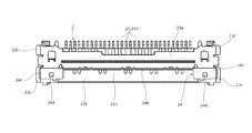
リセプタクルコネクタ2に設けられたリセ側導電性シェル(コネクタ本体部)23も、絶縁ハウジング21に対して上下から挟む一対の上下シェル板23a,23bの嵌合体から構成されている。このリセ側導電性シェル23を構成している上シェル板23aおよび下シェル板23bも、導電性を有する薄板状の金属部材の折り曲げ構造体から形成されているが、上シェル板23aにおけるコネクタ長手方向の両端部分には、特に図9〜図16に示されているように、コネクタ長手方向の両側から絶縁ハウジング21を挟むようにして一対のホールドダウン23c,23c´が、印刷配線基板Pの表面から上方に立ち上がるように配置されている。
[Reset side conductive shell]
The receptacle-side conductive shell (connector body portion) 23 provided in the
すなわち、これらの両ホールドダウン23c,23c´は、リセ側導電性シェル23の両側壁板を構成するように、上シェル板23aのコネクタ長手方向の両端縁部における前端側及び後端側からそれぞれ下方に折り曲げられて形成されたものであって、当該両ホールドダウン23c,23c´の下端縁部分がコネクタ長手方向の外方に向かって延出するように略直角に折り曲げられて基板接続部になされている。それらの各基板接続部は、印刷配線基板P上に形成されたグランド接続用の導電路に対して半田接合され、それによってグランド回路の電気的な接続が行われるとともに、リセプタクルコネクタ2の全体が強固に固定されるようになっている。
That is, these hold-
ここで、上述した上シェル板23aは、例えば図10に示す様に絶縁ハウジング21の嵌合空間を形成している上側壁部の外表面に沿って平面状の天井板をなすように延在しているとともに、下シェル板23bは、絶縁ハウジング21の嵌合空間を形成している下側壁部の内表面に沿って平面状の底板をなすように延在している。このリセ側導電性シェル23における上シェル板23aの前端縁部分は、下シェル板23bの上方位置においてコネクタ長手方向に延在する配置関係になされている。これらの上シェル板23aの前端縁部分と、下シェル板23bとの間部分には、横長状に延在するシェル挿入開口部が形成されている。
Here, the above-described
このリセ側導電性シェル23に設けられたシェル挿入開口部は、例えば図9に示す様に前述した絶縁ハウジング21側の挿入開口部21aを前方側に向かって露出させる配置関係になされており、上シェル板23aの前端縁部は、絶縁ハウジング21側の挿入開口部21aを形成している上側壁部の前端縁部に対して上方側から、前後方向に位置合わせされた状態に重なり合うように配置されている。そして、このリセ側導電性シェル23のシェル挿入開口部により前方側に露出状態とされた絶縁ハウジング21の挿入開口部21aを通して、前述したようにプラグコネクタ1の嵌合突部11aが、リセプタクルコネクタ2の内部に形成されている嵌合空間に挿入されるようになっている。
For example, as shown in FIG. 9, the shell insertion opening provided in the receptacle-side
上述したように、リセ側導電性シェル23を構成している上シェル板23aの前端縁部分は、絶縁ハウジング21側の挿入開口部21aを形成している上側壁部の前端縁部に対して上方側から位置合わせされた状態に重なり合わされているが、当該リセ側導電性シェル23の上シェル板23aの前端縁部分には、長手方向に一定の間隔をなして複数体(3体)のシェル係合穴部23dが設けられている。これらの各シェル係合穴部23dは、上シェル板23aの前端縁部分の一部を、絶縁ハウジング21の挿入開口部21aの内方側に向かって湾曲状に折り曲げられた爪状部分に貫通形成されている。
As described above, the front end edge portion of the
一方、このようなリセ側導電性シェル23側の各シェル係合穴部23dに対応して、絶縁ハウジング21の前端縁部には、複数体(3体)のハウジング突起片21bが、コネクタ長手方向に一定の間隔をなして設けられている。これらの各ハウジング突起片21bは、絶縁ハウジング21の前端縁部から前方に向かって突出するように形成されている。そして、絶縁ハウジング21にリセ側導電性シェル23が装着された際に、上述したリセ側導電性シェル23側の各シェル係合穴部23dに対して当該ハウジング突起片21bが挿通状態になされ、それによって両部材21,23同士が、前後・左右方向に位置ズレを生じることを防止すると共に、リセ側導電性シェル23が絶縁ハウジング21から浮き上がることなく固定状態に維持されるようになっている。
On the other hand, a plurality of (three)
[リセプタクルコネクタの嵌合保持部材について]
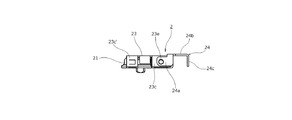
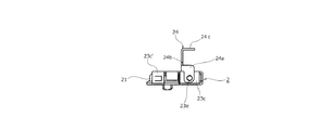
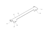
ここで、相手コネクタとしてのプラグコネクタ1がリセプタクルコネクタ2に嵌合されたときの両電気コネクタ1,2同士の嵌合状態は、リセプタクルコネクタ2のコネクタ本体部を構成しているリセ側導電性シェル23に回動可能に取り付けられた板状部材の折り曲げ体からなる嵌合保持部材(嵌合操作レバー)24の保持力によって維持される構成が採用されている。すなわち、プラグコネクタ1が、リセプタクルコネクタ2に嵌合された時点において、それまで図13〜図16のように「待機位置」に立たされた状態にある嵌合保持部材24を、組立て作業者が把持しながら適宜の回動力を付与することによって、図9〜図12に示された「作用位置」まで押し倒すように回動させることで、両電気コネクタ1,2同士が一定範囲内の外力によっては分離することなく嵌合状態に維持されるようになっている。
[Receptacle connector fitting holding member]
Here, when the
一方、リセプタクルコネクタ2に嵌合したプラグコネクタ1を、リセプタクルコネクタ2から抜去する際においては、「作用位置」にあった嵌合保持部材24を上方に向かって開放操作させるようにして「待機位置」に戻すことにより、両電気コネクタ1,2同士が抜去可能な状態になされる。
On the other hand, when the
より具体的には、上述したリセ側導電性シェル(コネクタ本体部)23に設けられた両ホールドダウン23c,23c´のうちのコネクタ前方側に配置されたホールドダウン23cには、例えば図16に示す様にコネクタ外方側に突出する回動軸部23eが設けられており、その回動軸部23eに対して、図17〜図18に示されている嵌合保持部材(嵌合操作レバー)24の回動腕部24aが回転可能に装着されている。この回動腕部24aは、リセ側導電性シェル23のコネクタ長手方向の両側部分に一対設けられているが、それら一対の回動腕部24a,24a同士が、コネクタ長手方向に延在する平板状部材からなる保持主板24bにより一体的に連結されている。
More specifically, the hold-
このような両回動腕部24a,24aが装着された回動軸部23e,23eは、上述したようにコネクタ前方側のホールドダウン23cの基板接続部に対して、直上に相当する位置に配置されている。そして、それらの各回動軸部23eを中心として回動される嵌合保持部材(嵌合操作レバー)24が、図9のように「作用位置」に押し倒された状態に回動された状態にあっては、前述した絶縁ハウジング(コネクタ本体部)21の挿入開口部21aにおける上方側の前方側領域を、平板状部材からなる保持主板24bが上方側から部分的に覆う構成になされている。このように保持主板24bがプラグコネクタ1の略全体を覆うことで、電磁遮蔽が良好に行われてシールド性を向上させることが出来る。
The
これに対して、図13〜図16に示されているように、保持主板24bが「待機位置」に立ち上がるように起こされた場合においては、絶縁ハウジング21の挿入開口部21aから保持主板24bが上方に離間した状態となり、挿入開口部21aの全体が完全に開放された状態になされる。
On the other hand, as shown in FIGS. 13 to 16, when the holding
また、このような嵌合保持部材(嵌合操作レバー)24が、「作用位置」に回動された状態(図9〜図12参照)において、上述した保持主板24bの前端部分に相当する位置に配置された端縁部分には、板状片からなる一対の係合保持板24c,24cが下方に向かって延出するように連設されている。これらの両係合保持板24c,24cは、上述した保持主板24bにおけるコネクタ長手方向の両端部分から略直角に折れ曲がるように延出している。そして、嵌合状態になされたプラグコネクタ(相手コネクタ)1に、後述するように設けられた外方延出部13d,13dの背面部分に対して、当該両係合保持板24c,24cが、コネクタ後方側の外方から接触配置される構成になされている。
Further, in a state where such a fitting holding member (fitting operation lever) 24 is rotated to the “operating position” (see FIGS. 9 to 12), a position corresponding to the front end portion of the holding
より具体的には、特に図5〜図8に示されているように、前述したプラグコネクタ(相手コネクタ)1に連結された同軸ケーブルSCを挟んだ両側外方部分、すなわちプラグ側導電性シェル13におけるコネクタ長手方向の両端部分には、コネクタ長手方向の外方に向かって突出する中空の角柱状部材からなる外方延出部13d,13dが設けられている。これらの外方延出部13d,13dにおける後端側(背面側)の立上り面は、前述した嵌合保持部材(嵌合操作レバー)24の回動半径の方向における最外郭面を構成し、かつ嵌合方向(コネクタ前後方向)に対して略直交する平坦面になされている。そして、その嵌合方向に略直交する最外郭面としての外方延出部13d,13dの後端側(背面側)の立上り面には、コネクタ後方側に向かって突出する嵌合係止突起片13e,13eが設けられている。
More specifically, as shown in FIGS. 5 to 8, the outer portions on both sides sandwiching the coaxial cable SC connected to the plug connector (mating connector) 1 described above, that is, the plug-side conductive shell. 13 are provided with outwardly extending
一方、上述したプラグコネクタ(相手コネクタ)1側の嵌合係止突起片13e,13eに対応して、リセプタクルコネクタ2側の保持主板24bに設けられた係合保持板24c,24cには、貫通穴からなる嵌合係合穴部24d,24dが形成されている。そして、図21に示されているように、嵌合保持部材(嵌合操作レバー)24が「待機位置」に回動された状態から、図22のようにプラグコネクタ(相手コネクタ)1の嵌合が行われた後に、嵌合保持部材(嵌合操作レバー)24が「作用位置」に回動されると(図1参照)、リセプタクルコネクタ2側の嵌合保持部材24に設けられた嵌合係合穴部24d,24dが、プラグコネクタ(相手コネクタ)1の最外郭面に設けられた嵌合係止突起片13e,13eに入り込むようにして係合状態になされる。その結果、図1のように、嵌合保持部材24を介して両電気コネクタ1,2同士が連結された状態になされ、それによって両電気コネクタ1,2同士の嵌合状態が維持される。
On the other hand, the
以上述べた構成を備えた本実施形態によれば、印刷配線基板Pに実装されて固定状態になされたリセプタクルコネクタ2に嵌合保持部材(嵌合操作レバー)24が取り付けられていることから、当該嵌合保持部材24は、印刷配線基板Pにより安定的に保持された状態となる。従って、そのように安定的に保持された嵌合保持部材24を介して、相手コネクタとしてのプラグコネクタ1の嵌合状態が良好に維持される。
According to the present embodiment having the above-described configuration, the fitting holding member (fitting operation lever) 24 is attached to the
このとき、特に本実施形態においては、嵌合保持部材24が係合される相手コネクタとしてのプラグコネクタ1の被係合面が、嵌合保持部材24の回動半径方向の最外郭面であり、かつ嵌合方向と略直交する面になされていることから、プラグコネクタ(相手コネクタ)1に対する嵌合保持部材24の係合力が、極めて安定的に得られる。
At this time, particularly in the present embodiment, the engaged surface of the
さらに、本実施形態においては、嵌合保持部材(嵌合操作レバー)24が、リセプタクルコネクタ2のホールドダウン23cに設けられた基板接続部の近傍に回動可能に取り付けられており、印刷配線基板Pに固定された部分に対して嵌合保持部材24が直接的に取り付けられていることから、嵌合保持部材24の保持が確実に行われ、プラグコネクタ(相手コネクタ)1との嵌合状態が一層高められる。
Further, in the present embodiment, the fitting holding member (fitting operation lever) 24 is rotatably attached in the vicinity of the board connecting portion provided in the hold down 23c of the
以上、本発明者によってなされた発明を実施形態に基づき具体的に説明したが、本発明は上述した実施形態に限定されるものではなく、その要旨を逸脱しない範囲で種々変形可能であるというのはいうまでもない。 Although the invention made by the present inventor has been specifically described based on the embodiments, the present invention is not limited to the above-described embodiments, and various modifications can be made without departing from the scope of the invention. Needless to say.
例えば、上述した実施形態では、嵌合保持部材が板状をなすように形成されているが、棒状などのような他の形状とすることも可能である。 For example, in the above-described embodiment, the fitting holding member is formed to have a plate shape, but other shapes such as a rod shape may be used.
また本発明は、上述した実施形態のような同軸ケーブル用コネクタに限定されることはなく、絶縁ケーブル用コネクタや、同軸ケーブルと絶縁ケーブルとが複数混合したタイプの電気コネクタや、フレキシブル配線基板等が連結される電気コネクタ、プリント基板同士を接続する基板対基板コネクタ、あるいは、プラグコネクタを介さずに直接的にフレキシブル配線基板をコネクタ内部に収容し電気的に接続するコネクタ等についても同様に適用することが可能である。 Further, the present invention is not limited to the coaxial cable connector as in the above-described embodiment, but is an insulated cable connector, a type of electrical connector in which a plurality of coaxial cables and insulated cables are mixed, a flexible wiring board, etc. The same applies to electrical connectors that are connected to each other, board-to-board connectors that connect printed boards to each other, or connectors that house a flexible wiring board directly inside the connector without using a plug connector, etc. Is possible.
以上のように本実施形態は、各種電気機器に使用される多種多様な電気コネクタに対して広く適用することが可能である。 As described above, the present embodiment can be widely applied to a wide variety of electrical connectors used in various electrical devices.
1 プラグコネクタ(相手コネクタ)
11 絶縁ハウジング(コネクタ本体部)
11a 嵌合突部
12 導電コンタクト部材(プラグ側コンタクト部材)
12a 端子電極部
13 プラグ側導電性シェル(コネクタ本体部)
13a 上シェル板
13b 下シェル板
13c グランド接続舌片
13d 外方延出部
13e 嵌合係止突起片
14 グランドバー
SC 同軸ケーブル(信号伝送媒体)
SCa ケーブル中心導体(信号線)
SCb ケーブル外部導体(シールド線)
2 リセプタクルコネクタ
21 絶縁ハウジング(コネクタ本体部)
21a 挿入開口部
21b ハウジング突起片
22 導電コンタクト部材(リセ側コンタクト部材)
23 リセ側導電性シェル(コネクタ本体部)
23a 上シェル板
23b 下シェル板
23c,23c´ ホールドダウン
23d シェル係合穴部
23e 回動軸部
24 嵌合保持部材(嵌合操作レバー)
24a 回動腕部
24b 保持主板
24c 係合保持板
24d 嵌合係合穴部
1 Plug connector (mating connector)
11 Insulation housing (connector body)
12a
13a
SCa Cable center conductor (signal line)
SCb Cable outer conductor (shielded wire)
2
23 Rise side conductive shell (connector body)
23a
24a
Claims (6)
前記嵌合保持部材は、前記コネクタ本体部に回動可能に設けられ、前記作用位置に回動操作されたときに前記相手コネクタに対して係合した状態に維持される構成になされていることを特徴とする電気コネクタ。 The mating connector is fitted to the connector main body mounted on the wiring board, and the mating connector is maintained in the mating state by the fitting holding member that is rotated from the standby position to the operating position. In the electrical connector configured as follows:
The fitting holding member is rotatably provided on the connector main body, and is configured to be maintained in a state of being engaged with the mating connector when being rotated to the operation position. An electrical connector featuring.
前記嵌合保持部材は、前記導電性シェルの前記基板接続部の近傍に回動可能に取り付けられていることを特徴とする請求項1記載の電気コネクタ。 The conductive shell covering the insulating housing is provided with a board connecting portion connected to the wiring board,
The electrical connector according to claim 1, wherein the fitting holding member is rotatably attached in the vicinity of the board connecting portion of the conductive shell.
Priority Applications (1)
| Application Number | Priority Date | Filing Date | Title |
|---|---|---|---|
| JP2016087201A JP2017199466A (en) | 2016-04-25 | 2016-04-25 | Electric connector |
Applications Claiming Priority (1)
| Application Number | Priority Date | Filing Date | Title |
|---|---|---|---|
| JP2016087201A JP2017199466A (en) | 2016-04-25 | 2016-04-25 | Electric connector |
Publications (2)
| Publication Number | Publication Date |
|---|---|
| JP2017199466A true JP2017199466A (en) | 2017-11-02 |
| JP2017199466A5 JP2017199466A5 (en) | 2019-05-09 |
Family
ID=60238105
Family Applications (1)
| Application Number | Title | Priority Date | Filing Date |
|---|---|---|---|
| JP2016087201A Pending JP2017199466A (en) | 2016-04-25 | 2016-04-25 | Electric connector |
Country Status (1)
| Country | Link |
|---|---|
| JP (1) | JP2017199466A (en) |
Citations (5)
| Publication number | Priority date | Publication date | Assignee | Title |
|---|---|---|---|---|
| JPS6262781U (en) * | 1985-10-08 | 1987-04-18 | ||
| JPH11297421A (en) * | 1998-04-15 | 1999-10-29 | Amp Japan Ltd | Connector with locking member |
| JP2011187367A (en) * | 2010-03-10 | 2011-09-22 | I-Pex Co Ltd | Connector device |
| JP2011238410A (en) * | 2010-05-07 | 2011-11-24 | I-Pex Co Ltd | Electric connector and electric connector assembly |
| JP2016018614A (en) * | 2014-07-04 | 2016-02-01 | 第一精工株式会社 | Connector device |
-
2016
- 2016-04-25 JP JP2016087201A patent/JP2017199466A/en active Pending
Patent Citations (5)
| Publication number | Priority date | Publication date | Assignee | Title |
|---|---|---|---|---|
| JPS6262781U (en) * | 1985-10-08 | 1987-04-18 | ||
| JPH11297421A (en) * | 1998-04-15 | 1999-10-29 | Amp Japan Ltd | Connector with locking member |
| JP2011187367A (en) * | 2010-03-10 | 2011-09-22 | I-Pex Co Ltd | Connector device |
| JP2011238410A (en) * | 2010-05-07 | 2011-11-24 | I-Pex Co Ltd | Electric connector and electric connector assembly |
| JP2016018614A (en) * | 2014-07-04 | 2016-02-01 | 第一精工株式会社 | Connector device |
Similar Documents
| Publication | Publication Date | Title |
|---|---|---|
| KR101735945B1 (en) | Electrical connector and apparatus thereof | |
| JP4335256B2 (en) | Electrical connector | |
| TWI621309B (en) | Electric connector | |
| KR101809824B1 (en) | Electrical connector and apparatus thereof | |
| JP4618745B1 (en) | Electrical connector | |
| JP2012230820A (en) | Coaxial electric connector | |
| JP2011238410A (en) | Electric connector and electric connector assembly | |
| TW201312875A (en) | Coaxial electrical connector and coaxial electrical connector assembly | |
| EP3316406B1 (en) | Electronic device and connector | |
| JP2021096960A (en) | Electrical connector and electrical connector device | |
| US20140357108A1 (en) | Plug connector and method of manufacturing the same | |
| WO2011086857A1 (en) | Electrical connector and electrical connector assembly | |
| JP6044609B2 (en) | Connector connection structure | |
| JP5110403B2 (en) | Electrical connector and electrical connector assembly | |
| JP2014222648A (en) | Connector device | |
| JP2012064536A (en) | Connector assembly | |
| JP2011138687A (en) | Electrical connector | |
| JP2016076352A (en) | Electric connector | |
| JP2017199466A (en) | Electric connector | |
| JP2007234491A (en) | Connector | |
| WO2017187709A1 (en) | Usb connector | |
| JP2000299167A (en) | Electric connector | |
| JP2019079621A (en) | Connector for coaxial cable | |
| JP2016146318A (en) | Coaxial type electric connector | |
| KR101296699B1 (en) | The electric connector and the electric connector assembly |
Legal Events
| Date | Code | Title | Description |
|---|---|---|---|
| A521 | Request for written amendment filed |
Free format text: JAPANESE INTERMEDIATE CODE: A523 Effective date: 20160428 |
|
| A521 | Request for written amendment filed |
Free format text: JAPANESE INTERMEDIATE CODE: A523 Effective date: 20190401 |
|
| A621 | Written request for application examination |
Free format text: JAPANESE INTERMEDIATE CODE: A621 Effective date: 20190401 |
|
| A977 | Report on retrieval |
Free format text: JAPANESE INTERMEDIATE CODE: A971007 Effective date: 20191203 |
|
| A131 | Notification of reasons for refusal |
Free format text: JAPANESE INTERMEDIATE CODE: A131 Effective date: 20191209 |
|
| A521 | Request for written amendment filed |
Free format text: JAPANESE INTERMEDIATE CODE: A523 Effective date: 20200114 |
|
| A131 | Notification of reasons for refusal |
Free format text: JAPANESE INTERMEDIATE CODE: A131 Effective date: 20200512 |
|
| A521 | Request for written amendment filed |
Free format text: JAPANESE INTERMEDIATE CODE: A523 Effective date: 20200623 |
|
| A02 | Decision of refusal |
Free format text: JAPANESE INTERMEDIATE CODE: A02 Effective date: 20200821 |