JP2017196965A - Automatic drive control device and automatic drive control method - Google Patents
Automatic drive control device and automatic drive control method Download PDFInfo
- Publication number
- JP2017196965A JP2017196965A JP2016087929A JP2016087929A JP2017196965A JP 2017196965 A JP2017196965 A JP 2017196965A JP 2016087929 A JP2016087929 A JP 2016087929A JP 2016087929 A JP2016087929 A JP 2016087929A JP 2017196965 A JP2017196965 A JP 2017196965A
- Authority
- JP
- Japan
- Prior art keywords
- sub
- main
- operation amount
- ecu
- unit
- Prior art date
- Legal status (The legal status is an assumption and is not a legal conclusion. Google has not performed a legal analysis and makes no representation as to the accuracy of the status listed.)
- Granted
Links
Images


Abstract
Description
この発明は、車両の自動運転を制御する技術に関する。 The present invention relates to a technique for controlling automatic driving of a vehicle.
自動運転制御装置は、高い信頼性が求められるため、複数のCPU(Central Processing Unit)で同一処理を行って処理結果を比較する冗長系システムを組むことが一般的である。冗長系システムを組むにあたり、単純にシステムの各部品を多重化するとシステム規模が大きくなるため、システム規模を抑えつつ信頼性を高めるための発明がなされている。 Since an automatic operation control device is required to have high reliability, it is common to form a redundant system that performs the same processing with a plurality of CPUs (Central Processing Units) and compares the processing results. In assembling a redundant system, simply multiplexing each component of the system increases the system scale. Therefore, an invention for increasing the reliability while suppressing the system scale has been made.
例えば、特許文献1の車両用操舵制御装置は、操舵制御値を算出するメインCPUとサブCPUとを備えて構成される。サブCPUは、メインCPUよりも長い制御周期で操舵制御値を求めると共に、メインCPUと同じ制御周期で操舵制御値の符号のみを簡易演算する。メインCPUに異常が検出されれば、車両用操舵制御装置は直ちにモータ制御を停止し、運転者はモータによるアシスト無しで操舵制御を行なう。この車両用操舵制御装置によれば、サブCPUはメインCPUよりもロースペックのものを用いることができる。 For example, the vehicle steering control device disclosed in Patent Literature 1 includes a main CPU and a sub CPU that calculate a steering control value. The sub CPU obtains the steering control value at a control cycle longer than that of the main CPU, and simply calculates only the sign of the steering control value at the same control cycle as the main CPU. If an abnormality is detected in the main CPU, the vehicle steering control device immediately stops motor control, and the driver performs steering control without assistance from the motor. According to this vehicle steering control device, a sub-CPU having a lower spec than the main CPU can be used.
また、特許文献2の自動運転制御装置は、運転者の要求信号および車両状態信号に基づいて操作量指令値を演算する操作量生成ノードと、当該操作量生成ノードからの操作量指令値に基づいてアクチュエータを制御するアクチュエータ駆動ノードとを備えて構成される。各ノードは故障検出機能を備えており、操作量生成ノードが故障した場合は、アクチュエータ駆動ノードが運転者の要求信号を受けて、操作量指令値を演算する。この自動運転制御装置によれば、操作量生成ノードを多重化せずとも、操作量生成ノードの故障時にシステムが制御不能に陥らず、運転者による運転が継続可能である。 Further, the automatic driving control device of Patent Document 2 is based on an operation amount generation node that calculates an operation amount command value based on a driver's request signal and a vehicle state signal, and an operation amount command value from the operation amount generation node. And an actuator drive node for controlling the actuator. Each node has a failure detection function, and when the operation amount generation node fails, the actuator drive node receives a driver's request signal and calculates an operation amount command value. According to this automatic operation control device, even if the operation amount generation node is not multiplexed, the system does not become uncontrollable when the operation amount generation node fails, and the driving by the driver can be continued.
一方、近年は車両の自動運転に関する技術開発が進められている。自動運転では、車両の運転に必要な、認知、判断、および操作が自動化される。非特許文献1では自動運転システムのアーキテクチャが示されている。認知を担う地図モジュールは、カメラまたはレーダなどの複数のセンサと、GPS情報とから、自車周辺の道路情報と障害物情報を含んだローカルダイナミックマップを作製する。判断を担う人工知能モジュールは、ローカルダイナミックマップを基に走行経路を決定する。操作を担う速度制御モジュールおよび操舵制御モジュールは、走行経路を基に速度や操舵角を制御する。 On the other hand, in recent years, technological development relating to automatic driving of vehicles has been promoted. In automatic driving, recognition, judgment, and operation necessary for driving a vehicle are automated. Non-Patent Document 1 shows an architecture of an automatic driving system. The map module responsible for recognition creates a local dynamic map including road information and obstacle information around the vehicle from a plurality of sensors such as cameras or radar and GPS information. The artificial intelligence module responsible for the determination determines the travel route based on the local dynamic map. The speed control module and the steering control module responsible for the operation control the speed and the steering angle based on the travel route.
特許文献1の車両用操舵制御装置および特許文献2の自動運転制御装置は、電動パワーステアリングまたは自動ブレーキなどを制御対象にしているため、あくまでも運転者が主体となる運転操作を補助する用途に過ぎない。そのため、故障発生時には制御不能に陥らず、運転者による制御が継続可能であれば良かった。 Since the vehicle steering control device of Patent Literature 1 and the automatic driving control device of Patent Literature 2 are targeted for electric power steering or automatic braking, etc., they are merely used to assist the driving operation mainly by the driver. Absent. Therefore, it is only necessary that the control by the driver can be continued without causing the control to be disabled when a failure occurs.
しかしながら、車両の自動運転においては、単一故障が発生しても一定時間は自動運転を継続することが求められる。なぜなら、運転者は、自動運転の継続不能の通知を受けてから車両周囲の状況を確認し、運転を安全に行なえると判断してから、自身の操作による運転を開始するからである。したがって、特許文献1の車両用操舵制御装置および特許文献2の自動運転制御装置のように、単一故障で自動運転を直ちに停止してしまうと、例えば交差点の右折中においては自車が、他車または歩行者と接触しうる問題点があった。なお、多重系のシステムにより単一故障が起きても自動運転を継続する手法も知られているが、この場合はシステム規模が大きくなるという問題点があった。 However, in the automatic driving of the vehicle, it is required to continue the automatic driving for a certain time even if a single failure occurs. This is because the driver checks the situation around the vehicle after receiving the notification that the automatic driving cannot be continued, determines that the driving can be safely performed, and then starts driving by his own operation. Therefore, as in the case of the vehicle steering control device of Patent Document 1 and the automatic driving control device of Patent Document 2, if the automatic driving is immediately stopped due to a single failure, for example, when the vehicle is turning right at the intersection, There were problems that could come into contact with cars or pedestrians. There is also known a method of continuing automatic operation even when a single failure occurs due to a multiplex system, but in this case, there is a problem that the system scale becomes large.
非特許文献1の自動運転システムは、車間距離または白線距離の情報を、操作を担うモジュール群に入力する構成になっており、人工知能モジュールからの指示がなくても自動運転の継続が可能である。しかしながら、故障の検出方法および故障検出後の動作については示されていない。 The automatic driving system of Non-Patent Document 1 is configured to input information on the inter-vehicle distance or the white line distance to the module group responsible for the operation, and automatic driving can be continued without an instruction from the artificial intelligence module. is there. However, the failure detection method and the operation after failure detection are not shown.
この発明は、上記のような問題点を解決するためになされたものであり、小規模なシステムで、単一故障が起きても車両の自動運転制御を継続することを目的とする。 The present invention has been made to solve the above-described problems, and an object of the present invention is to continue automatic driving control of a vehicle even if a single failure occurs in a small-scale system.
本発明に係る第1の自動運転制御装置は、メインECUに設けられ、複数のセンサを用いて車両の自動運転制御に関する操作量をメイン操作量として演算するメイン演算部と、サブECUに設けられ、メイン演算部よりも少数のセンサを用いて車両の自動運転制御に関する操作量をサブ操作量として演算するサブ演算部と、メインECUおよびサブECUの故障を検出する故障検出部と、故障検出部の故障検出結果に基づき、メイン操作量またはサブ操作量のいずれかを選択する操作量選択部と、操作量選択部が選択した操作量に基づき車両の自動運転制御を行う自動運転制御部と、を備える。 A first automatic driving control device according to the present invention is provided in a main ECU, and is provided in a sub ECU with a main calculation unit that calculates an operation amount related to automatic driving control of the vehicle as a main operation amount using a plurality of sensors. A sub operation unit that calculates an operation amount related to automatic driving control of the vehicle as a sub operation amount using a smaller number of sensors than the main operation unit, a failure detection unit that detects a failure of the main ECU and the sub ECU, and a failure detection unit An operation amount selection unit that selects either the main operation amount or the sub operation amount based on the failure detection result, an automatic operation control unit that performs automatic driving control of the vehicle based on the operation amount selected by the operation amount selection unit, Is provided.
また、本発明に係る第2の自動運転制御装置は、メインECUに設けられ、複数のセンサを用いて車両の自動運転制御に関する操作量をメイン操作量として演算するメイン演算部と、サブECUに設けられ、車両の自動運転制御に関する操作量をサブ操作量として演算するサブ演算部と、メインECUおよびサブECUの故障を検出する故障検出部と、故障検出部の故障検出結果に基づき、メイン操作量またはサブ操作量のいずれかを選択する操作量選択部と、操作量選択部が選択した操作量に基づき車両の自動運転制御を行う自動運転制御部と、を備え、サブ演算部は、メイン演算部よりも少数のセンサを用いてサブ操作量を演算する第1サブ演算部と、メイン演算部よりも演算周期が長く、第1サブ演算部よりも多数のセンサを用いてサブ操作量を演算する第2サブ演算部と、を備え、サブECUは、第1サブ演算部または第2サブ演算部のいずれか一方を選択して動作させるサブ演算切替部をさらに備える。 A second automatic driving control apparatus according to the present invention is provided in the main ECU, and includes a main calculation unit that calculates an operation amount related to automatic driving control of the vehicle as a main operation amount using a plurality of sensors, and a sub ECU. A sub-operation unit that calculates an operation amount related to automatic driving control of the vehicle as a sub-operation amount; a failure detection unit that detects a failure of the main ECU and the sub-ECU; and a main operation based on a failure detection result of the failure detection unit An operation amount selection unit that selects either the amount or the sub operation amount, and an automatic operation control unit that performs automatic operation control of the vehicle based on the operation amount selected by the operation amount selection unit. A first sub calculation unit that calculates a sub operation amount using a smaller number of sensors than the calculation unit, and a calculation cycle that is longer than that of the main calculation unit, and more sensors than the first sub calculation unit. Includes a second sub-arithmetic unit for calculating the operation amount, the sub-ECU further includes a sub-operation switching unit to operate by selecting either the first sub-arithmetic unit or the second sub-arithmetic unit.
本発明に係る自動運転制御方法は、メインECUにおいて、複数のセンサを用いて車両の自動運転制御に関する操作量をメイン操作量として演算し、サブECUにおいて、車両の自動運転制御に関する操作量をメインECUよりも少数のセンサを用いてサブ操作量として演算し、メインECUおよびサブECUの故障を検出し、メインECUまたはサブECUの故障検出結果に基づきメイン操作量またはサブ操作量のいずれかを選択し、選択した操作量に基づき車両の自動運転制御を行う。 In the automatic driving control method according to the present invention, an operation amount related to automatic driving control of a vehicle is calculated as a main operating amount using a plurality of sensors in a main ECU, and an operating amount related to automatic driving control of the vehicle is calculated in a sub ECU. Calculates as sub-operation amount using fewer sensors than ECU, detects failure of main ECU and sub-ECU, and selects either main operation amount or sub-operation amount based on failure detection result of main ECU or sub-ECU Then, automatic driving control of the vehicle is performed based on the selected operation amount.
メインECUとサブECUの一方に単一故障が発生しても、故障していない他方のECUの演算結果を用いて、車両の自動運転制御を行うことが出来るため、自動運転の継続が可能である。また、サブECUでは、車両の自動運転制御に関する操作量がメインECUにおけるよりも少ない単位時間演算量で演算されるため、サブECUにはメインECUに比べてロースペックな部品を用いることができる。従って、システム規模を抑制することが出来る。 Even if a single failure occurs in one of the main ECU and sub-ECU, automatic operation control of the vehicle can be performed using the calculation result of the other ECU that has not failed, so automatic operation can be continued. is there. Further, in the sub ECU, the operation amount related to the automatic driving control of the vehicle is calculated with a unit time calculation amount smaller than that in the main ECU, and therefore, the low-spec components can be used for the sub ECU compared to the main ECU. Therefore, the system scale can be suppressed.
<A.実施の形態1>
図1は、本発明の実施の形態1に係る自動運転制御装置101の構成を例示するブロック図である。自動運転制御装置101は、車両の自動運転を制御する装置であり、例えば制御すべき車両に搭載されている。本明細書では、自動運転制御装置の制御対象となる車両を単に「車両」と呼ぶ。
<A. Embodiment 1>
FIG. 1 is a block diagram illustrating a configuration of an automatic
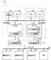
自動運転制御装置101は、メインECU(Engine Control Unit)11、サブECU21、センサ31,32,33、GPS(Global Positioning System)受信機34、駆動系ECU41、操舵系ECU51、制動系ECU61、およびHMI(Human Machine Interface)7を備えて構成される。メインECU11、サブECU21、センサ31,32,33、およびGPS受信機34はネットワーク81で接続される。メインECU11、サブECU21、駆動系ECU41、操舵系ECU51、制動系ECU61、およびHMI7はネットワーク82で接続される。
The automatic
メインECU11は、ネットワーク81を介してセンサ31,32,33のデータおよびGPS受信機34の位置情報を取得し、メイン操作量a1およびメイン故障検出通知b1を出力する。本明細書では、メインECU11が出力する操作量と、後述するサブECU21が出力する操作量とを区別するために、前者を「メイン操作量a1」、後者を「サブ操作量a2」と呼ぶが、特に両者を区別しない場合には単に「操作量a1,a2」と呼ぶ。メイン故障検出通知b1とは、メインECU11の故障検出通知のことであり、これに対して、後述するサブECU21の故障検出通知はサブ故障検出通知b2と呼ぶ。しかし、メイン故障検出通知b1とサブ故障検出通知b2とを特に区別しない場合には単に「故障検出通知b1,b2」と呼ぶ。メインECU11は、メイン故障検出部111およびメイン演算部112を有し、これらは20ミリ秒(ms)周期で動作する。
The
サブECU21は、ネットワーク81を介してセンサ31,32のデータを取得し、サブ操作量a2およびサブ故障検出通知b2を出力する。サブECU21は、サブ故障検出部211およびサブ演算部212を有しており、これらは20ミリ秒(ms)周期で動作する。
The
駆動系ECU41は、ネットワーク82を介してメインECU11からメイン操作量a1およびメイン故障検出通知b1を、サブECU21からサブ操作量a2およびサブ故障検出通知b2をそれぞれ取得し、アクセル用アクチュエータ(図示せず)を作動させる。ただし、メイン故障検出通知b1とサブ故障検出通知b2とは二者択一であり同時に駆動系ECU41に取得されるものではない。駆動系ECU41は、メイン操作量a1とサブ操作量a2のうち一方を選択する操作量選択部411を有しており、操作量選択部411で選択した操作量を用いて、アクセル用アクチュエータを作動させる。
The
操舵系ECU51は、ネットワーク82を介してメインECU11からメイン操作量a1およびメイン故障検出通知b1を、サブECU21からサブ操作量a2およびサブ故障検出通知b2をそれぞれ取得し、ステアリング用アクチュエータ(図示せず)を作動させる。ただし、メイン故障検出通知b1とサブ故障検出通知b2とは二者択一であり同時に操舵系ECU51に取得されるものではない。操舵系ECU51は、メイン操作量a1とサブ操作量a2のうち一方を選択する操作量選択部511を有しており、操作量選択部511で選択した操作量を用いて、ステアリング用アクチュエータを作動させる。
The
制動系ECU61は、ネットワーク82を介してメインECU11からメイン操作量a1およびメイン故障検出通知b1を、サブECU21からサブ操作量a2およびサブ故障検出通知b2をそれぞれ取得し、ブレーキ用アクチュエータ(図示せず)を作動させる。制動系ECU61は、メイン操作量a1とサブ操作量a2のうち一方を選択する操作量選択部611を有しており、操作量選択部611で選択した操作量を用いて、ブレーキ用アクチュエータを作動させる。
The
すなわち、駆動系ECU41、操舵系ECU51、制動系ECU61は、車両の自動運転制御を行う自動運転制御部として機能する。
That is, the
HMI7は、ネットワーク82を介してメイン故障検出通知b1またはサブ故障検出通知b2を取得し、取得した故障検出通知に応じて故障個所を音声または表示で運転者に通知し、運転者による運転と車両の修理を促す。
The
メイン演算部112は、センサ31,32,33のデータおよびGPS受信機34の位置情報からメイン操作量a1を演算する。メイン演算部112は、例えば非特許文献1の自動運転システムアーキテクチャに示されるように、センサ31,32,33のデータとGPS受信機34の位置情報とからローカルダイナミックマップを作成し、ローカルダイナミックマップを基に走行経路を作成し、走行経路を基にメイン操作量a1を作成する。センサ31,32,33には、例えばミリ波レーダ、レーザーレーダ、またはカメラを用いることができる。これらのセンサは単独で複雑な環境を認識することが困難であるため、複数のセンサを用いるセンサフュージョン技術によって認識性能を向上し、高精度なローカルダイナミックマップを作製できる。
The
サブ演算部212は、センサ31,32のデータからサブ操作量a2を演算する。サブ演算部212の有する機能の第1の例は、カメラが認識した車線から逸脱しないように制御する、車線逸脱防止支援機能である。車線逸脱防止支援機能には、本田技研工業株式会社のレーンキープアシストシステム(LKAS:Lane Keep Assist System、登録商標)、あるいはトヨタ自動車株式会社のレーンキーピングアシスト(LKA:Lane Keeping Assist、登録商標)等がある。サブ演算部212の有する機能の第2の例は、ミリ波レーダにより先行車との車間距離を検知し、車間距離を保つように制御する、アダプティブクルーズコントロール(ACC:Adaptive Cruise Control)機能である。
The
メイン演算部112は、センサ31,32,33のデータおよびGPS受信機34の位置情報を用いてメイン操作量a1を演算するのに対し、サブ演算部212は、センサ31,32のデータを用いてサブ操作量a2を演算する。このように、サブ演算部212は、メイン演算部112よりも少数のセンサを用いてサブ操作量a2を演算するため、単位時間あたりの演算量、すなわち単位時間演算量がメイン演算部112に比べて少ないという特徴がある。従って、サブECU21にはメインECU11よりもロースペックな部品を使うことができるため、同スペックの部品でメインECU11とサブECU21に同じスペックの部品を使う場合に比べて、自動運転制御装置101のシステム規模を抑制することができる。
The
メイン故障検出部111は、メインECU11の故障を検出したら、メイン故障検出通知b1を、ネットワーク82を介して駆動系ECU41の操作量選択部411、操舵系ECU51の操作量選択部511、制動系ECU61の操作量選択部611、およびHMI7に送信する。サブ故障検出部211は、サブECU21の故障を検出したら、サブ故障検出通知b2を、ネットワーク82を介して駆動系ECU41の操作量選択部411、操舵系ECU51の操作量選択部511、制動系ECU61の操作量選択部611、およびHMI7に送信する。
When the main
図2は、メイン故障検出部111の動作を例示するフローチャートである。以下、図2に沿ってメイン故障検出部111の動作を説明する。まず、メイン故障検出部111は、メイン演算部112が現周期で演算したメイン操作量a1と、現周期より前のステップS13で記録したメイン操作量a1とを比較し、メイン操作量a1の変動が正常か否かを判断する(ステップS11)。メイン故障検出部111は、メイン操作量a1の変動を正常ではない、すなわち異常と判断すると、メインECU11が故障したと判断し、メイン故障検出通知b1を操作量選択部411,511,611およびHMI7に送信する(ステップS12)。メイン故障検出部111は、メイン操作量a1の変動を正常と判断すると、メイン演算部112が現周期で演算したメイン操作量a1をメインECU11に記録する(ステップS13)。
FIG. 2 is a flowchart illustrating the operation of the main
ステップS11において、メイン故障検出部111は、現周期と一つ前の周期との間でメイン操作量a1の差分が閾値を超えた場合に、メイン操作量a1の変動が異常であると判断してもよい。あるいは、メイン故障検出部111は、現周期と一つ前の周期との間と、現周期と2つ前の周期との間の両方で、メイン操作量a1の差分が閾値を超えた場合に、メイン操作量a1の変動が異常であると判定してもよい。
In step S11, the main
図2の例で、メイン故障検出部111は、メイン操作量a1の変動が大きい場合にメインECU11が故障したと判断している。この判断方法は、メイン演算部112は、現在の車両周辺状況をフィードバックして次の操作量を決めているため、単位演算周期間においてメイン操作量a1が大きく変動することは無いという前提に基づいている。
In the example of FIG. 2, the main
以上、メイン故障検出部111の動作を説明したが、サブ故障検出部211の動作もこれと同様である。上記したメイン故障検出部111の動作の説明において、メイン演算部112をサブ演算部212、メインECU11をサブECU21、メイン操作量a1をサブ操作量a2、メイン故障検出通知b1をサブ故障置検出通知b2にそれぞれ置き換えれば、サブ故障検出部211の動作の説明となる。
The operation of the main
操作量選択部411,511,611は、それぞれ、駆動系ECU41、操舵系ECU51、制動系ECU61について、故障検出通知b1,b2に応じて操作量a1,a2のどちらかを選択する。図3は、操作量選択部411,511,611の動作の一例を示している。以下、図3に沿って操作量選択部411,511,611の動作を説明する。
The
まず、操作量選択部411,511,611は、メインECU11が故障したか否かを判定する(ステップS21)。具体的には、操作量選択部411,511,611はメイン故障検出通知b1を取得した場合に、メインECU11が故障したと判定する。操作量選択部411,511,611は、メインECU11が故障したと判定した場合、サブ操作量a2を選択し(ステップS22)、メインECU11が故障していないと判定した場合、メイン操作量a1を選択する(ステップS23)。
First, the operation
本実施の形態に係る自動運転制御装置101では、センサ31,32,33のデータおよびGPS受信機34の位置情報を通信するネットワーク81と、操作量および故障検出通知を通信するネットワーク82とを分けていた。しかし、図4に示す変形例に係る自動運転制御装置101Aにおけるように、これらを共通のネットワーク83で実現しても良い。また、信頼性を上げるために、ネットワーク81,82,83が冗長化されていてもよい。
In the automatic
また、上記の説明では、メイン演算部112で用いるセンサの数量を3、サブ演算部212で用いるセンサの数量を2としたが、サブ演算部212で用いるセンサの数量がメイン演算部112で用いるセンサの数量よりも少なければ、他の値でもよい。
In the above description, the number of sensors used in the
また、上記の説明では、メイン演算部112とサブ演算部212の演算周期を20msとしたが、両者の演算周期が同じであれば他の値でもよい。
In the above description, the calculation cycle of the
以上で説明したように、本実施の形態に係る自動運転制御装置101は、メインECU11に設けられ、複数のセンサ31,32,33を用いて車両の自動運転制御に関する操作量をメイン操作量a1として演算するメイン演算部112と、サブECU21に設けられ、メイン演算部112よりも少数のセンサ31,32を用いて車両の自動運転制御に関する操作量をサブ演算量a2として演算するサブ演算部212と、メインECU11の故障を検出するメイン故障検出部111と、サブECU21の故障を検出するサブ故障検出部211と、メイン故障検出部111およびサブ故障検出部211の故障検出結果に基づき、メイン操作量a1またはサブ操作量a2のいずれかを選択する操作量選択部411,511,611と、操作量選択部411,511,611が選択した操作量に基づき車両の自動運転制御を行う駆動系ECU41、操舵系ECU51、および制動系ECU61と、を備える。なお、メイン故障検出部111とサブ故障検出部211は別の構成である必要はなく、メインECU11およびサブECU21の故障を検出する故障検出部として構成されていれば良い。このような構成により、メインECU11とサブECU21の一方に単独故障が生じても、故障していない他方のECUによって自動運転制御を継続することができる。さらに、サブ演算部212の単位時間の演算量がメイン演算部112よりも少ないことから、サブECU21はメインECU11よりもロースペックの部品を用いて構成することができる。従って、同じスペックの部品を用いてメインECU11とサブECU21を構成する場合に比べて、自動運転制御装置101のシステムの規模を抑制することができる。
As described above, the automatic
また、自動運転制御装置101によれば、操作量選択部411,511,611は、メイン故障検出部111がメインECU11の故障を検出した場合に、サブ操作量a2を選択するため、メインECUの単独故障時にサブECUによる自動運転制御が継続可能である。
Further, according to the automatic
また、自動運転制御装置101によれば、メイン演算部112が用いるセンサ31,32,33は、サブ演算部212が用いるセンサ31,32を包含している。このように、メイン演算部112が用いる複数のセンサのうちのいくつかをサブ演算部212で用いることによって、メインECU11の故障時には、サブECU21により精度を落としつつもロースペックに自動運転を継続できる。
Further, according to the automatic
また、本実施の形態に係る自動運転制御方法によれば、メインECU11において、複数のセンサ31,32,33を用いて車両の自動運転制御に関する操作量をメイン操作量a1として演算し、サブECU21において、車両の自動運転制御に関する操作量をメインECU11よりも少数のセンサを用いてサブ操作量a2として演算し、メインECU11およびサブECU21の故障を検出し、メインECU11またはサブECU21の故障検出結果に基づき、選択したメイン操作量a1またはサブ操作量a2のいずれかに基づき車両の自動運転制御を行う。従って、メインECU11とサブECU21の一方に単独故障が生じても、故障していない他方のECUによって自動運転制御を継続することができる。また、サブ演算部212の単位時間の演算量がメイン演算部112よりも少ないことから、サブECU21にはメインECU11よりもロースペックの部品を用いることができ構成することができ、自動運転制御を行うシステムの規模を抑制することができる。
Further, according to the automatic driving control method according to the present embodiment, the
<B.実施の形態2>
実施の形態1に係る自動運転制御装置では、メインECU11自身がメインECU11の故障を検出するメイン故障検出部111を有し、駆動系ECU41、操舵系ECU51、および制動系ECU61がそれぞれ操作量選択部411,511,611を有していた。しかし、実施の形態2に係る自動運転制御装置では、メインECUの故障を検出する故障検出部をメインECUと独立して設け、操作量選択部を駆動系ECU、操舵系ECU、および制動系ECUと独立して設けることを特徴とする。
<B. Second Embodiment>
In the automatic driving control apparatus according to the first embodiment, the
図5は、本発明の実施の形態2に係る自動運転制御装置102の構成を示すブロック図である。図5において、図1に示した実施の形態1と同一または対応する構成要素には同一の参照符号を付している。自動運転制御装置102は、メインECU12、サブECU22、センサ31,32,33、GPS受信機34、ネットワーク81,82、駆動系ECU42、操舵系ECU52、制動系ECU62、HMI7、および制御切替部9を備えて構成される。
FIG. 5 is a block diagram showing the configuration of the automatic
自動運転制御装置102のメインECU12は、自動運転制御装置101のメインECU11と異なりメイン故障検出部を有していない。
Unlike the
サブECU22は、サブ故障検出部221とサブ演算部212とを備える。なお、図5では、サブ故障検出部221をサブECU内に設けているが、サブ故障検出部221はサブECU22と独立していてもよい。
The
制御切替部9は、メインECU12からメイン操作量a1を、サブECU22からサブ操作量a2およびサブ故障検出通知b2を取得し、メイン操作量a1またはサブ操作量a2のうち選択した操作量aと、サブ故障検出通知b2またはメイン故障検出通知b1とを出力する。制御切替部9は、メイン故障検出部91と操作量選択部92を備えている。制御切替部9が操作量選択部92を有する代わりに、駆動系ECU42、操舵系ECU52、および制動系ECU62は、実施の形態1の駆動系ECU41、操舵系ECU51、および制動系ECU61と異なり、操作量選択部を有していない。
The
駆動系ECU42、操舵系ECU52、および制動系ECU62は、ネットワーク82を介して操作量aを取得し、操作量aを用いてそれぞれアクセル用、ステアリング用、ブレーキ用アクチュエータを作動させる。
The
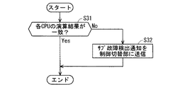
サブ故障検出部221は、サブECU22の故障を検出したらサブ故障検出通知b2を制御切替部9に送信する。図6は、サブ故障検出部221の動作を例示するフローチャートである。図6の例では、サブECU22のサブ演算部212を実現するCPUまたはCPUコアが冗長化されており、サブ故障検出部221は、それら冗長化されたCPUまたはCPUのコアによる演算結果を比較することで故障を検出する。
When the sub
以下、図6に沿ってサブ故障検出部221の動作を説明する。サブ故障検出部221は、サブ演算部212を実現する冗長化されたCPUまたはCPUコアの演算結果が一致するか否かを判断する(ステップS31)。ステップS31で演算結果が一致していなければ、サブ故障検出部221はサブECU22が故障したと判断し、サブ故障検出通知b2を制御切替部9に送信する(ステップS32)。ステップS31で演算結果が一致していれば、サブ故障検出部221は処理を終了する。
Hereinafter, the operation of the sub
図7は、メイン故障検出部91の動作の一例を示すフローチャートである。図7の例では、サブECU22が故障していない場合に、メイン操作量a1とサブ操作量a2とを比較してメインECU12の故障を検出する。
FIG. 7 is a flowchart showing an example of the operation of the main
図7のフローチャートに沿ってメイン故障検出部91の動作を説明する。まずメイン故障検出部91は、サブECU22が故障したか否かを判断する(ステップS41)。具体的には、メイン故障検出部91は、サブ故障検出通知b2を取得したかを確認し、取得していればサブECU22が故障したと判定する。そして、サブECU22が故障していればメイン故障検出部91は処理を終了する。サブECU22が故障していなければ、メイン故障検出部91はメイン操作量a1をサブ操作量a2と比較し、メイン操作量a1が正常か否かを判定する(ステップS42)。メイン故障検出部91はステップS42でメイン操作量a1を正常ではない、すなわち異常と判定すると、メインECU12が故障したと判断し、メイン故障検出通知a1を操作量選択部92に送信する(ステップS43)。メイン故障検出部91は、ステップS42でメイン操作量a1を正常と判定すると、そのまま処理を終了する。ステップS42において、メイン故障検出部91は、例えばメイン操作量a1とサブ操作量a2の差分が閾値を超えたら異常と判定してもよい。あるいは、メイン故障検出部91は、メイン操作量a1とサブ操作量a2の差分が一定時間以上、継続して閾値を超えた場合に異常と判定することによって、異常と誤判定することを防ぐこともできる。
The operation of the main
操作量選択部92は、故障検出通知に基づき、メイン操作量a1とサブ操作量a2のいずれかを選択し、操作量aとする。具体的には、操作量選択部92は、メイン故障検出通知b1を取得した場合には、サブ操作量a2を選択し、サブ故障検出通知b2を取得した場合、またはいずれの故障検出通知も取得しなかった場合には、メイン操作量a1を選択する。操作量選択部92が選択した操作量aは、ネットワーク82を介して駆動系ECU42、操舵系ECU52、および制動系ECU62に送られ、駆動系ECU42、操舵系ECU52、および制動系ECU62は、操作量aに基づきアクセル用、ステアリング用、およびブレーキ用アクチュエータを作動する。
The operation
実施の形態2の自動運転制御装置102によれば、実施の形態1の効果に加えて、以下の効果を得る。すなわち、自動運転制御装置102では、メインECU12が故障した時にサブECU22に制御を切り替えるための操作量選択部92が、駆動系ECU42、操舵系ECU52、および制動系ECU62と独立しているため、駆動系ECU42、操舵系ECU52、および制動系ECU62に操作量選択部を設ける必要がなく、構成を簡略化することができる。
According to the automatic
<C.実施の形態3>
実施の形態1では、サブ演算部が有する機能の例として、車線逸脱防止支援機能またはACC機能を挙げた。車線逸脱防止支援機能またはACC機能は、一般道に比べて認知すべき障害物の少ない、高速道路での利用を強く推奨されているため、一般道での自動運転継続に問題があった。そこで、サブECUの演算周期を長くすることにより単位時間演算量を低くし、ロースペックなサブECUを用いて一般道での車線逸脱防止支援機能等を実現することが考えられる。しかし、演算周期を長くすると、高速運転時に演算が間に合わないことがあるため、高速道路での自動運転継続に問題があった。
<C. Embodiment 3>
In Embodiment 1, the lane departure prevention support function or the ACC function is given as an example of the function of the sub-calculation unit. The lane departure prevention support function or the ACC function is strongly recommended for use on expressways with fewer obstacles to be recognized than ordinary roads. Therefore, it is conceivable to reduce the amount of calculation per unit time by increasing the calculation cycle of the sub ECU, and to realize a lane departure prevention support function on a general road using a low-spec sub ECU. However, if the calculation cycle is lengthened, the calculation may not be in time during high-speed driving, and there has been a problem in continuing automatic driving on a highway.
そこで、実施の形態3では、サブECUに演算周期の異なる2つのサブ演算部を設け、車両が高速で走行する際には、演算周期の短いサブ演算部で演算を行って演算の遅延を防ぐ一方、車両が一般道路を走行する際には、演算周期の長いサブ演算部で演算を行うことによって、認知量の多さに対応する。 Therefore, in the third embodiment, the sub-ECU is provided with two sub-calculation units having different calculation cycles, and when the vehicle travels at a high speed, the sub-calculation unit having a short calculation cycle performs the calculation to prevent calculation delay. On the other hand, when the vehicle travels on a general road, the sub-calculation unit having a long calculation cycle performs the calculation to cope with a large amount of recognition.
図8は、本実施の形態に係る自動運転制御装置103の構成を示すブロック図である。図8において、図1に示した実施の形態1と同一または対応する構成要素には同一の参照符号を付している。自動運転制御装置103は、実施の形態1の自動運転制御装置101と比較すると、サブECU21に代えてサブECU23を備えている。サブECU23は、サブ故障検出部211、第1サブ演算部232、第2サブ演算部233、およびサブ演算切替部234を備えている。自動運転制御装置103のその他の構成は実施の形態1に係る自動運転制御装置101と同様である。
FIG. 8 is a block diagram showing a configuration of the automatic
第1サブ演算部232は、実施の形態1のサブ演算部212と同様である。すなわち、第1サブ演算部232は、メイン演算部112よりも少数のセンサ31,32のデータからサブ操作量a2を演算し、その動作周期は20ms周期である。
The first sub operation unit 232 is the same as the
第2サブ演算部233は、メイン演算部112および第1サブ演算部232よりも動作周期が長く、例えば60ms周期で動作する。第2サブ演算部233は、センサ31,32,33のデータとGPS受信機34の位置情報とからサブ操作量a2を演算する。すなわち、第2サブ演算部233は、メイン演算部112よりも演算周期が長く、第1サブ演算部232よりも多数のセンサ31,32,33を用いてサブ操作量a2を演算する。また、第1サブ演算部232が用いるセンサ31,32,33は、第2サブ演算部233が用いるセンサ31,32を包含している。また、メイン演算部112が用いるセンサ31,32,33は、第2サブ演算部233が用いるセンサ31,32を包含している。また、メイン演算部112が用いるセンサ31,32,33は、第2サブ演算部233が用いるセンサ31,32,33を包含している。
The second sub operation unit 233 has an operation cycle longer than that of the
サブ演算切替部234は、メイン演算部112および第1サブ演算部232と同じ20ms周期で動作し、第1サブ演算部232または第2サブ演算部233のいずれか一方を選択して動作させる。すなわち、第1サブ演算部232と第2サブ演算部233は同時には動作しない。
The sub calculation switching unit 234 operates at the same 20 ms cycle as the
図9,10は、サブ演算切替部234の動作を例示するフローチャートである。図9は、車両の速度に応じてサブ演算部の切り替えを行う場合を示し、図10は、車両の走行道路が高速道路か否かに応じてサブ演算部の切り替えを行う場合を示している。なお、上記のとおり第2サブ演算部233の動作周期はサブ演算切替部234の動作周期の3倍であるため、第2サブ演算部233がサブ操作量a2を演算する場合、3回同じ演算結果を出力する。 9 and 10 are flowcharts illustrating the operation of the sub-operation switching unit 234. FIG. 9 shows a case where the sub-calculation unit is switched according to the speed of the vehicle, and FIG. 10 shows a case where the sub-calculation unit is switched according to whether the traveling road of the vehicle is an expressway. . As described above, since the operation cycle of the second sub operation unit 233 is three times the operation cycle of the sub operation switching unit 234, the same operation is performed three times when the second sub operation unit 233 calculates the sub operation amount a2. Output the result.
図9に沿って、サブ演算切替部234の動作を説明する。まず、サブ演算切替部234は、車両が高速運転しているか否かを判断する(ステップS51)。ここでサブ演算切替部234は、車両の速度が閾値を超えたら高速運転と判定してもよい。あるいは、サブ演算切替部234は、車両の速度が一定時間以上継続して閾値を超えたら高速運転と判定し、その状態から一定時間以上継続して閾値以下であれば高速運転との判定を解除することにより、頻繁な切替を抑制しても良い。サブ演算切替部234は、ステップS51で高速運転していると判断した場合、第1サブ演算部232を選択する(ステップS52)。また、サブ演算切替部234は、ステップS51で高速運転していないと判断した場合、第2サブ演算部233を選択する(ステップS53)。 The operation of the sub-operation switching unit 234 will be described with reference to FIG. First, the sub-calculation switching unit 234 determines whether or not the vehicle is operating at high speed (step S51). Here, the sub-calculation switching unit 234 may determine that the vehicle is operating at high speed when the vehicle speed exceeds a threshold value. Alternatively, the sub-calculation switching unit 234 determines that the vehicle is driving at high speed when the vehicle speed continues for a certain time or more and exceeds the threshold value, and cancels the determination for high-speed driving if the vehicle speed continues from that state for a certain time or more and is less than the threshold value By doing so, frequent switching may be suppressed. If the sub-operation switching unit 234 determines that the high-speed operation is performed in Step S51, the sub-operation switching unit 234 selects the first sub-calculation unit 232 (Step S52). On the other hand, when determining that the high-speed operation is not performed in Step S51, the sub-calculation switching unit 234 selects the second sub-calculation unit 233 (Step S53).
次に、図10に沿って、サブ演算切替部234の動作を説明する。まず、サブ演算切替部234は、車両が高速道路を走行しているか否かを判断する(ステップS61)。車両が高速道路を走行しているか否かの判断は、GPS受信機34の位置情報、すなわちGPS情報から行ってもよいし、ETC車載器(図示せず)の入出場情報、すなわちETC情報から行っても良い。それ以外は図9と同様である。
Next, the operation of the sub-operation switching unit 234 will be described with reference to FIG. First, the sub-calculation switching unit 234 determines whether or not the vehicle is traveling on an expressway (step S61). The determination as to whether or not the vehicle is traveling on an expressway may be made from the position information of the
なお、実施の形態3では、第2サブ演算部233の演算周期を60msとし、それ以外の部の演算周期を20msとしたが、それ以外の部に比べて第2サブ演算部233の演算周期が長ければ、他の値でもよい。 In the third embodiment, the calculation cycle of the second sub calculation unit 233 is set to 60 ms, and the calculation cycle of the other units is set to 20 ms. However, the calculation cycle of the second sub calculation unit 233 is compared to the other units. Other values may be used as long as.
また、実施の形態3において、第2サブ演算部233で用いるセンサの数は、メイン演算部112と同じとしたが、第1サブ演算部232で用いるセンサの数よりも多ければ、メイン演算部112で用いるセンサの数以下であっても良い。
In the third embodiment, the number of sensors used in the second sub calculation unit 233 is the same as that of the
以上のように、本実施の形態に係る自動運転制御装置103は、メインECU11に設けられ、複数のセンサ31,32,33を用いて車両の自動運転制御に関する操作量をメイン操作量a1として演算するメイン演算部112と、サブECU23に設けられ、車両の自動運転制御に関する操作量をサブ操作量a2として演算するサブ演算部232,233と、メインECU11の故障を検出するメイン故障検出部111と、サブECU23の故障を検出するサブ故障検出部211と、メイン故障検出部111およびサブ故障検出部211の故障検出結果に基づき、メイン操作量a1またはサブ操作量a2のいずれかを選択する操作量選択部411,511,611と、操作量選択部411,511,611が選択した操作量に基づき車両の自動運転制御を行う駆動系ECU41、操舵系ECU51、および制動系ECU61と、を備える。なお、メイン故障検出部111とサブ故障検出部211は別の構成である必要はなく、メインECU11およびサブECU21の故障を検出する故障検出部として構成されていれば良い。また、サブ演算部232,233は、メイン演算部112よりも少数のセンサ31,32を用いてサブ操作量a2を演算する第1サブ演算部232と、メイン演算部112よりも演算周期が長く、第1サブ演算部232よりも多数のセンサ31,32,33を用いてサブ操作量a2を演算する第2サブ演算部233と、を備え、サブECU23は、第1サブ演算部232または第2サブ演算部233のいずれか一方を選択して動作させるサブ演算切替部234を備える。自動運転制御装置103によれば、実施の形態1の効果に加えて、以下の効果を奏する。すなわち、自動運転制御装置103によれば、短い周期で自動運転制御を行う必要がある場合には、周期が短いが用いるセンサが少ない第1サブ演算部232を使用し、多くのセンサの使用が求められる場合には、周期が長いが用いるセンサが多い第2サブ演算部233を使用することによって、サブECU23の単位時間演算量をメインECU11より少なくしつつ、異なる走行状況に対応することができる。
As described above, the automatic
また、操作量選択部411,511,611は、メイン故障検出部111がメインECU11の故障を検出した場合に、サブ操作量a2を選択するため、メインECUの単独故障時にサブECUによる自動運転制御が継続可能である。
Further, since the operation
例えば、サブ演算切替部234は、車両の走行速度に基づき、第1サブ演算部232または第2サブ演算部233のいずれか一方を選択して動作させる。従って、高速走行時には、第1サブ演算部232を用いて演算を行うことで、メイン演算部112と同様の演算周期で自動運転を継続できる。また、低速走行時には、第2サブ演算部233を用いて演算を行うことで、メイン演算部112と同様の認知精度で自動運転を継続できる。従って、自動運転制御装置103によれば、低速走行時の自動運転制御の信頼性を高めることができる。
For example, the sub calculation switching unit 234 selects and operates either the first sub calculation unit 232 or the second sub calculation unit 233 based on the traveling speed of the vehicle. Therefore, when driving at high speed, the automatic operation can be continued with the same calculation cycle as that of the
あるいは、サブ演算切替部234は、車両が一般道よりも障害物の少ない高速道路を走行している場合には、第1サブ演算部232を選択して動作させることで、メイン演算部112と同様の演算周期で自動運転を継続できる。また、車両が高速道路以外を走行している場合には、第2サブ演算部233を選択して動作させることで、メイン演算部112による制御と同様の認知精度で自動運転制御を継続できる。したがって、自動運転制御装置103によれば、一般道路走行時の信頼性を高めることができる。
Alternatively, the sub-calculation switching unit 234 selects and operates the first sub-calculation unit 232 when the vehicle is traveling on an expressway with fewer obstacles than general roads, Automatic operation can be continued in the same calculation cycle. When the vehicle is traveling on a road other than an expressway, the automatic driving control can be continued with the same recognition accuracy as the control by the main calculating
また、自動運転制御装置103によれば、第1サブ演算部232が用いるセンサ31,32,33は、第2サブ演算部233が用いるセンサ31,32を包含している。このように、第1サブ演算部232が用いる複数のセンサのうちのいくつかを第2サブ演算部233で用いることによって、第1サブ演算部232と第2サブ演算部233を切替えて動作させても、自動運転制御を継続できる。
Further, according to the automatic
また、自動運転制御装置103によれば、メイン演算部112が用いるセンサ31,32,33は、第2サブ演算部233が用いるセンサ31,32を包含している。このように、メイン演算部112が用いる複数のセンサのうちのいくつかを第2サブ演算部233で用いることによって、メインECU11が故障した場合でも、サブECU23に切り替えて自動運転制御を継続できる。
Further, according to the automatic
また、自動運転制御装置103によれば、メイン演算部112が用いるセンサ31,32,33は、第1サブ演算部232が用いるセンサ31,32,33を包含している。このように、メイン演算部112が用いる複数のセンサのうちのいくつかを第1サブ演算部232で用いることによって、メインECU11が故障した場合でも、サブECU23に切り替えて自動運転制御を継続できる。
Further, according to the automatic
<D.ハードウェア構成>
図11は、実施の形態1の自動運転制御装置101におけるメインECU11のハードウェア構成を示す図である。図11に示すように、メインECU11は、プロセッサ1001と、メモリ1002とによって実現される。メインECU11が備えるメイン故障検出部111又はメイン演算部112は、メモリ1002に記憶されたプログラムをプロセッサ1001が読み出して実行することにより、実現される。
<D. Hardware configuration>
FIG. 11 is a diagram illustrating a hardware configuration of the
ここで、プロセッサ1001は、例えば中央処理装置、処理装置、演算装置、マイクロプロセッサ、マイクロコンピュータ、Digital Signal Processor等である。また、メモリ1002には、例えば、RAM(Random Access Memory)、ROM(Read Only Memory)、フラッシュメモリ、EPROM(Electrically Programmable Read Only Memory)、EEPROM(Electrically Erasable Programmable Read Only Memory)などの、不揮発性または揮発性の半導体メモリ、HDD(Hard Disk Drive)、磁気ディスク、フレキシブルディスク、光ディスク、コンパクトディスク、ミニディスク、DVD(Digital Versatile Disk)及びそのドライブ装置の少なくともいずれか1つが含まれる。
Here, the
メインECU12、サブECU21,22,23、駆動系ECU41,42、操舵系ECU51,52、制動系ECU61,62、および制御切替部9のハードウェア構成も、図11に示すメインECU11のハードウェア構成と同様である。
The hardware configuration of the
なお、本発明は、その発明の範囲内において、各実施の形態を自由に組み合わせたり、各実施の形態を適宜、変形、省略したりすることが可能である。 It should be noted that the present invention can be freely combined with each other within the scope of the invention, and each embodiment can be appropriately modified or omitted.
7 HMI、9 操作量選択部、11,12 メインECU、21,22,23 サブECU、31,32,33 センサ、41,42 駆動系ECU、51,52 操舵系ECU、61,62 制動系ECU、81,82,83 ネットワーク、91,111 メイン故障検出部、92 操作量選択部、112 メイン演算部、211,221 サブ故障検出部、212 サブ演算部、411,511,611 操作量選択部、1001 プロセッサ、1002 メモリ。
7 HMI, 9 Operation amount selection unit, 11, 12 Main ECU, 21, 22, 23 Sub ECU, 31, 32, 33 Sensor, 41, 42 Drive system ECU, 51, 52 Steering system ECU, 61, 62
Claims (13)
サブECUに設けられ、前記メイン演算部よりも少数のセンサを用いて車両の自動運転制御に関する操作量をサブ操作量として演算するサブ演算部と、
前記メインECUおよび前記サブECUの故障を検出する故障検出部と、
前記故障検出部の故障検出結果に基づき、前記メイン操作量または前記サブ操作量のいずれかを選択する操作量選択部と、
前記操作量選択部が選択した操作量に基づき前記車両の自動運転制御を行う自動運転制御部と、を備える、
自動運転制御装置。 A main ECU that is provided in the main ECU and calculates an operation amount related to automatic driving control of the vehicle as a main operation amount using a plurality of sensors;
A sub-operation unit that is provided in the sub-ECU and calculates an operation amount related to automatic driving control of the vehicle as a sub-operation amount using a smaller number of sensors than the main calculation unit;
A failure detection unit for detecting a failure of the main ECU and the sub ECU;
An operation amount selection unit that selects either the main operation amount or the sub operation amount based on the failure detection result of the failure detection unit;
An automatic operation control unit that performs automatic operation control of the vehicle based on the operation amount selected by the operation amount selection unit,
Automatic operation control device.
請求項1に記載の自動運転制御装置。 The operation amount selection unit selects the sub operation amount when the failure detection unit detects a failure of the main ECU.
The automatic operation control device according to claim 1.
サブECUに設けられ、車両の自動運転制御に関する操作量をサブ操作量として演算するサブ演算部と、
前記メインECUおよび前記サブECUの故障を検出する故障検出部と、
前記故障検出部の故障検出結果に基づき、前記メイン操作量または前記サブ操作量のいずれかを選択する操作量選択部と、
前記操作量選択部が選択した操作量に基づき前記車両の自動運転制御を行う自動運転制御部と、を備え、
前記サブ演算部は、
前記メイン演算部よりも少数のセンサを用いて前記サブ操作量を演算する第1サブ演算部と、
前記メイン演算部よりも演算周期が長く、前記第1サブ演算部よりも多数のセンサを用いて前記サブ操作量を演算する第2サブ演算部と、を備え、
前記サブECUは、前記第1サブ演算部または前記第2サブ演算部のいずれか一方を選択して動作させるサブ演算切替部をさらに備える、
自動運転制御装置。 A main ECU that is provided in the main ECU and calculates an operation amount related to automatic driving control of the vehicle as a main operation amount using a plurality of sensors;
A sub-operation unit that is provided in the sub-ECU and calculates an operation amount related to automatic driving control of the vehicle as a sub-operation amount;
A failure detection unit for detecting a failure of the main ECU and the sub ECU;
An operation amount selection unit that selects either the main operation amount or the sub operation amount based on the failure detection result of the failure detection unit;
An automatic operation control unit that performs automatic operation control of the vehicle based on the operation amount selected by the operation amount selection unit,
The sub-operation unit is
A first sub operation unit that calculates the sub operation amount using a smaller number of sensors than the main operation unit;
A second sub operation unit that has a calculation cycle longer than that of the main operation unit and calculates the sub operation amount using a larger number of sensors than the first sub operation unit;
The sub-ECU further includes a sub-operation switching unit that selects and operates either the first sub-operation unit or the second sub-operation unit.
Automatic operation control device.
請求項3に記載の自動運転制御装置。 The operation amount selection unit selects the sub operation amount when the failure detection unit detects a failure of the main ECU.
The automatic operation control device according to claim 3.
請求項3または4に記載の自動運転制御装置。 The sub-calculation switching unit selects and operates either the first sub-calculation unit or the second sub-calculation unit based on the traveling speed of the vehicle.
The automatic operation control device according to claim 3 or 4.
請求項3から5のいずれか1項に記載の自動運転制御装置。 The sub calculation switching unit selects and operates the first sub calculation unit when the vehicle is traveling on a highway, and the second sub calculation switching is performed when the vehicle is traveling on a road other than the highway. Select a part to operate,
The automatic operation control device according to any one of claims 3 to 5.
請求項6に記載の自動運転制御装置。 The sub-operation switching unit determines whether or not the vehicle is traveling on a highway based on GPS information.
The automatic operation control device according to claim 6.
請求項6に記載の自動運転制御装置。 The sub-operation switching unit determines whether or not the vehicle is traveling on a highway based on ETC information.
The automatic operation control device according to claim 6.
請求項3から8のいずれか1項に記載の自動運転制御装置。 The sensor used by the first sub calculation unit includes the sensor used by the second sub calculation unit.
The automatic operation control device according to any one of claims 3 to 8.
請求項3から9のいずれか1項に記載の自動運転制御装置。 The sensor used by the main calculation unit includes the sensor used by the second sub calculation unit.
The automatic operation control device according to any one of claims 3 to 9.
請求項3から9のいずれか1項に記載の自動運転制御装置。 The sensor used by the main calculation unit includes the sensor used by the first sub calculation unit.
The automatic operation control device according to any one of claims 3 to 9.
請求項1または2に記載の自動運転制御装置。 The sensor used by the main calculation unit includes the sensor used by the sub calculation unit.
The automatic operation control device according to claim 1 or 2.
サブECUにおいて、前記車両の自動運転制御に関する操作量を前記メインECUよりも少数のセンサを用いてサブ操作量として演算し、
前記メインECUおよび前記サブECUの故障を検出し、
前記メインECUまたは前記サブECUの故障検出結果に基づき、メイン操作量またはサブ操作量のいずれかを選択し、
前記選択した操作量に基づき前記車両の自動運転制御を行う、
自動運転制御方法。 In the main ECU, the operation amount related to the automatic driving control of the vehicle is calculated as a main operation amount using a plurality of sensors,
In the sub ECU, the operation amount related to the automatic driving control of the vehicle is calculated as a sub operation amount using a smaller number of sensors than the main ECU,
Detecting a failure of the main ECU and the sub ECU,
Based on the failure detection result of the main ECU or the sub ECU, either the main operation amount or the sub operation amount is selected,
Performing automatic driving control of the vehicle based on the selected operation amount;
Automatic operation control method.
Priority Applications (1)
| Application Number | Priority Date | Filing Date | Title |
|---|---|---|---|
| JP2016087929A JP6611664B2 (en) | 2016-04-26 | 2016-04-26 | Automatic operation control device and automatic operation control method |
Applications Claiming Priority (1)
| Application Number | Priority Date | Filing Date | Title |
|---|---|---|---|
| JP2016087929A JP6611664B2 (en) | 2016-04-26 | 2016-04-26 | Automatic operation control device and automatic operation control method |
Publications (2)
| Publication Number | Publication Date |
|---|---|
| JP2017196965A true JP2017196965A (en) | 2017-11-02 |
| JP6611664B2 JP6611664B2 (en) | 2019-11-27 |
Family
ID=60237128
Family Applications (1)
| Application Number | Title | Priority Date | Filing Date |
|---|---|---|---|
| JP2016087929A Active JP6611664B2 (en) | 2016-04-26 | 2016-04-26 | Automatic operation control device and automatic operation control method |
Country Status (1)
| Country | Link |
|---|---|
| JP (1) | JP6611664B2 (en) |
Cited By (26)
| Publication number | Priority date | Publication date | Assignee | Title |
|---|---|---|---|---|
| JP2019111866A (en) * | 2017-12-21 | 2019-07-11 | トヨタ自動車株式会社 | Automatic operation system |
| WO2019163010A1 (en) * | 2018-02-21 | 2019-08-29 | 本田技研工業株式会社 | Vehicle control system, vehicle control method, and program |
| WO2019176603A1 (en) | 2018-03-13 | 2019-09-19 | 日立オートモティブシステムズ株式会社 | Abnormality diagnosis system and abnormality diagnosis method |
| JP2019189029A (en) * | 2018-04-25 | 2019-10-31 | 株式会社デンソー | Vehicle control device |
| KR20200022674A (en) * | 2018-08-23 | 2020-03-04 | 현대자동차주식회사 | Apparatus for controlling fail-operational of vehicle, and method thereof |
| KR20200068770A (en) * | 2018-11-27 | 2020-06-16 | (주)언맨드솔루션 | Autonomous Emergency Control System |
| CN111348051A (en) * | 2018-12-20 | 2020-06-30 | 罗伯特·博世有限公司 | Information device for informing a driver and method for informing a driver |
| KR20200085325A (en) * | 2017-11-10 | 2020-07-14 | 크노르-브렘제 시스테메 퓌어 누츠파조이게 게엠베하 | System for at least semi-autonomous operation of cars with double redundancy |
| WO2020149090A1 (en) * | 2019-01-17 | 2020-07-23 | 日立オートモティブシステムズ株式会社 | Driving control system |
| JP6732143B1 (en) * | 2019-07-31 | 2020-07-29 | 三菱電機株式会社 | Vehicle control device |
| CN111661062A (en) * | 2019-03-05 | 2020-09-15 | 阿里巴巴集团控股有限公司 | Automatic driving control method, device and system |
| JP2020147106A (en) * | 2019-03-12 | 2020-09-17 | トヨタ自動車株式会社 | Vehicle operation system |
| CN112313136A (en) * | 2018-06-20 | 2021-02-02 | 三菱电机株式会社 | Automatic driving assistance system and operation method thereof |
| WO2021020294A1 (en) * | 2019-07-30 | 2021-02-04 | マツダ株式会社 | Vehicle control system |
| WO2021020293A1 (en) * | 2019-07-30 | 2021-02-04 | マツダ株式会社 | Vehicle control system |
| WO2021020191A1 (en) * | 2019-07-30 | 2021-02-04 | マツダ株式会社 | Vehicle control system |
| WO2021020286A1 (en) * | 2019-07-30 | 2021-02-04 | マツダ株式会社 | Vehicle control system |
| JP2021030974A (en) * | 2019-08-28 | 2021-03-01 | 本田技研工業株式会社 | Vehicle control system and vehicle control method |
| CN112867634A (en) * | 2018-09-10 | 2021-05-28 | 株式会社自动网络技术研究所 | Distribution branch box |
| KR20210090721A (en) * | 2018-12-11 | 2021-07-20 | 웨이모 엘엘씨 | Redundant Hardware Systems for Autonomous Vehicles |
| KR102365256B1 (en) * | 2020-11-13 | 2022-02-22 | 주식회사 현대케피코 | Motor control unit of vehicle and method for controlling the motor of vehicle |
| KR20220021788A (en) * | 2020-08-14 | 2022-02-22 | 동서콘트롤(주) | Cluster Using Dual CAN Communication |
| JP2022103645A (en) * | 2020-12-28 | 2022-07-08 | 本田技研工業株式会社 | Vehicle control device, vehicle control method, and program |
| WO2022208856A1 (en) * | 2021-04-01 | 2022-10-06 | 日本電信電話株式会社 | Communication system, switching device, switching method, and program |
| US11472406B2 (en) | 2019-12-27 | 2022-10-18 | Honda Motor Co., Ltd. | Vehicle control apparatus, vehicle, and vehicle control method |
| JP7213935B1 (en) | 2021-10-19 | 2023-01-27 | 三菱電機株式会社 | AUTOMATIC OPERATION CONTROL DEVICE AND AUTOMATIC OPERATION CONTROL METHOD |
-
2016
- 2016-04-26 JP JP2016087929A patent/JP6611664B2/en active Active
Cited By (61)
| Publication number | Priority date | Publication date | Assignee | Title |
|---|---|---|---|---|
| US11332158B2 (en) | 2017-11-10 | 2022-05-17 | Knorr-Bremse Systeme Fuer Nutzfahrzeuge Gmbh | System for the at least partially autonomous operation of a motor vehicle with double redundancy |
| KR102308679B1 (en) * | 2017-11-10 | 2021-10-05 | 크노르-브렘제 시스테메 퓌어 누츠파조이게 게엠베하 | Systems for at least semi-autonomous operation of automobiles with double redundancy |
| KR20200085325A (en) * | 2017-11-10 | 2020-07-14 | 크노르-브렘제 시스테메 퓌어 누츠파조이게 게엠베하 | System for at least semi-autonomous operation of cars with double redundancy |
| JP2019111866A (en) * | 2017-12-21 | 2019-07-11 | トヨタ自動車株式会社 | Automatic operation system |
| CN111727145A (en) * | 2018-02-21 | 2020-09-29 | 本田技研工业株式会社 | Vehicle control system, vehicle control method, and program |
| WO2019163010A1 (en) * | 2018-02-21 | 2019-08-29 | 本田技研工業株式会社 | Vehicle control system, vehicle control method, and program |
| CN111727145B (en) * | 2018-02-21 | 2023-05-26 | 本田技研工业株式会社 | Vehicle control system, vehicle control method, and storage medium |
| JPWO2019163010A1 (en) * | 2018-02-21 | 2020-12-03 | 本田技研工業株式会社 | Vehicle control systems, vehicle control methods, and programs |
| WO2019176603A1 (en) | 2018-03-13 | 2019-09-19 | 日立オートモティブシステムズ株式会社 | Abnormality diagnosis system and abnormality diagnosis method |
| EP3786021A4 (en) * | 2018-04-25 | 2021-06-30 | Denso Corporation | Vehicle control device |
| CN112004730B (en) * | 2018-04-25 | 2023-08-22 | 株式会社电装 | vehicle control device |
| WO2019208442A1 (en) | 2018-04-25 | 2019-10-31 | 株式会社デンソー | Vehicle control device |
| JP2019189029A (en) * | 2018-04-25 | 2019-10-31 | 株式会社デンソー | Vehicle control device |
| CN112004730A (en) * | 2018-04-25 | 2020-11-27 | 株式会社电装 | Vehicle control device |
| CN112313136A (en) * | 2018-06-20 | 2021-02-02 | 三菱电机株式会社 | Automatic driving assistance system and operation method thereof |
| KR102452555B1 (en) * | 2018-08-23 | 2022-10-07 | 현대자동차주식회사 | Apparatus for controlling fail-operational of vehicle, and method thereof |
| KR20200022674A (en) * | 2018-08-23 | 2020-03-04 | 현대자동차주식회사 | Apparatus for controlling fail-operational of vehicle, and method thereof |
| CN112867634A (en) * | 2018-09-10 | 2021-05-28 | 株式会社自动网络技术研究所 | Distribution branch box |
| KR102363544B1 (en) | 2018-11-27 | 2022-02-18 | (주)언맨드솔루션 | Autonomous Emergency Control System |
| KR20200068770A (en) * | 2018-11-27 | 2020-06-16 | (주)언맨드솔루션 | Autonomous Emergency Control System |
| US11912292B2 (en) | 2018-12-11 | 2024-02-27 | Waymo Llc | Redundant hardware system for autonomous vehicles |
| KR102511055B1 (en) | 2018-12-11 | 2023-03-17 | 웨이모 엘엘씨 | Redundancy Hardware System for Autonomous Vehicles |
| KR20210090721A (en) * | 2018-12-11 | 2021-07-20 | 웨이모 엘엘씨 | Redundant Hardware Systems for Autonomous Vehicles |
| CN111348051A (en) * | 2018-12-20 | 2020-06-30 | 罗伯特·博世有限公司 | Information device for informing a driver and method for informing a driver |
| US11827234B2 (en) | 2019-01-17 | 2023-11-28 | Hitachi Astemo, Ltd. | Driving control system |
| JP2020111296A (en) * | 2019-01-17 | 2020-07-27 | 日立オートモティブシステムズ株式会社 | Operation control system |
| JP7289657B2 (en) | 2019-01-17 | 2023-06-12 | 日立Astemo株式会社 | Drive unit command generator and vehicle control system |
| WO2020149090A1 (en) * | 2019-01-17 | 2020-07-23 | 日立オートモティブシステムズ株式会社 | Driving control system |
| CN111661062A (en) * | 2019-03-05 | 2020-09-15 | 阿里巴巴集团控股有限公司 | Automatic driving control method, device and system |
| JP2020147106A (en) * | 2019-03-12 | 2020-09-17 | トヨタ自動車株式会社 | Vehicle operation system |
| US11932270B2 (en) | 2019-03-12 | 2024-03-19 | Toyota Jidosha Kabushiki Kaisha | Vehicle driving system |
| CN111762182A (en) * | 2019-03-12 | 2020-10-13 | 丰田自动车株式会社 | Vehicle driving system |
| JP7238495B2 (en) | 2019-03-12 | 2023-03-14 | トヨタ自動車株式会社 | vehicle driving system |
| JP2021020647A (en) * | 2019-07-30 | 2021-02-18 | マツダ株式会社 | Vehicle control system |
| US20220281466A1 (en) * | 2019-07-30 | 2022-09-08 | Mazda Motor Corporation | Vehicle control system |
| CN114174140A (en) * | 2019-07-30 | 2022-03-11 | 马自达汽车株式会社 | Vehicle control system |
| CN114269619A (en) * | 2019-07-30 | 2022-04-01 | 马自达汽车株式会社 | Vehicle control system |
| JP2021020649A (en) * | 2019-07-30 | 2021-02-18 | マツダ株式会社 | Vehicle control system |
| JP2021020651A (en) * | 2019-07-30 | 2021-02-18 | マツダ株式会社 | Vehicle control system |
| JP7375357B2 (en) | 2019-07-30 | 2023-11-08 | マツダ株式会社 | vehicle control system |
| CN114269619B (en) * | 2019-07-30 | 2023-12-08 | 马自达汽车株式会社 | Vehicle control system |
| JP7346980B2 (en) | 2019-07-30 | 2023-09-20 | マツダ株式会社 | vehicle control system |
| JP2021020648A (en) * | 2019-07-30 | 2021-02-18 | マツダ株式会社 | Vehicle control system |
| JP7342495B2 (en) | 2019-07-30 | 2023-09-12 | マツダ株式会社 | vehicle control system |
| WO2021020294A1 (en) * | 2019-07-30 | 2021-02-04 | マツダ株式会社 | Vehicle control system |
| WO2021020286A1 (en) * | 2019-07-30 | 2021-02-04 | マツダ株式会社 | Vehicle control system |
| WO2021020191A1 (en) * | 2019-07-30 | 2021-02-04 | マツダ株式会社 | Vehicle control system |
| WO2021020293A1 (en) * | 2019-07-30 | 2021-02-04 | マツダ株式会社 | Vehicle control system |
| JP6732143B1 (en) * | 2019-07-31 | 2020-07-29 | 三菱電機株式会社 | Vehicle control device |
| JP7194092B2 (en) | 2019-08-28 | 2022-12-21 | 本田技研工業株式会社 | Vehicle control system and vehicle control method |
| JP2021030974A (en) * | 2019-08-28 | 2021-03-01 | 本田技研工業株式会社 | Vehicle control system and vehicle control method |
| US11472406B2 (en) | 2019-12-27 | 2022-10-18 | Honda Motor Co., Ltd. | Vehicle control apparatus, vehicle, and vehicle control method |
| KR102411690B1 (en) | 2020-08-14 | 2022-06-21 | 동서콘트롤(주) | Cluster Using Dual CAN Communication |
| KR20220021788A (en) * | 2020-08-14 | 2022-02-22 | 동서콘트롤(주) | Cluster Using Dual CAN Communication |
| KR102365256B1 (en) * | 2020-11-13 | 2022-02-22 | 주식회사 현대케피코 | Motor control unit of vehicle and method for controlling the motor of vehicle |
| US11628744B2 (en) | 2020-12-28 | 2023-04-18 | Honda Motor Co., Ltd. | Vehicle control device, vehicle control method, and storage medium |
| JP7179047B2 (en) | 2020-12-28 | 2022-11-28 | 本田技研工業株式会社 | VEHICLE CONTROL DEVICE, VEHICLE CONTROL METHOD, AND PROGRAM |
| JP2022103645A (en) * | 2020-12-28 | 2022-07-08 | 本田技研工業株式会社 | Vehicle control device, vehicle control method, and program |
| WO2022208856A1 (en) * | 2021-04-01 | 2022-10-06 | 日本電信電話株式会社 | Communication system, switching device, switching method, and program |
| JP2023060919A (en) * | 2021-10-19 | 2023-05-01 | 三菱電機株式会社 | Automatic operation control device and automatic operation control method |
| JP7213935B1 (en) | 2021-10-19 | 2023-01-27 | 三菱電機株式会社 | AUTOMATIC OPERATION CONTROL DEVICE AND AUTOMATIC OPERATION CONTROL METHOD |
Also Published As
| Publication number | Publication date |
|---|---|
| JP6611664B2 (en) | 2019-11-27 |
Similar Documents
| Publication | Publication Date | Title |
|---|---|---|
| JP6611664B2 (en) | Automatic operation control device and automatic operation control method | |
| JP6388871B2 (en) | Method for Driver Assistant Application | |
| JP7193289B2 (en) | In-vehicle electronic control system | |
| JP2019185246A (en) | Automatic driving control system | |
| JP2019142246A (en) | Vehicle control device | |
| JP7198056B2 (en) | Vehicle control device and vehicle control method | |
| JP6987714B2 (en) | Electronic control device | |
| US20190317492A1 (en) | Apparatus and method for providing safety strategy in vehicle | |
| US11318929B2 (en) | Electronic control apparatus, electronic control system, and electronic control method | |
| US11334067B2 (en) | Apparatus and method for providing safety strategy in vehicle | |
| US20220212692A1 (en) | Automated driving control system and automated driving control apparatus | |
| JP5663946B2 (en) | Vehicle travel control device | |
| WO2019207639A1 (en) | Action selection device, action selection program, and action selection method | |
| Becker et al. | System architecture and safety requirements for automated driving | |
| JP6689337B2 (en) | Automatic operation control device and automatic operation control method | |
| CN111696374A (en) | Information processing device and automatic travel control system including the same | |
| US20230020415A1 (en) | Vehicle control system, vehicle integrated control device, electronic control device, network communication device, vehicle control method and computer readable medium | |
| WO2019244366A1 (en) | Autonomous driving assistance system and operation method therefor | |
| JP7213935B1 (en) | AUTOMATIC OPERATION CONTROL DEVICE AND AUTOMATIC OPERATION CONTROL METHOD | |
| EP4089498A1 (en) | Autonomous driving system, autonomous driving control method, and non-transitory storage medium | |
| US11853146B2 (en) | Vehicle and control method thereof | |
| JP2019197399A (en) | Route determination device of vehicle | |
| CN113391614A (en) | Method for determining capability boundaries and associated risks of a safety redundant autonomous driving system in real time | |
| WO2023084581A1 (en) | Electronic control device and vehicle control system | |
| US20220410934A1 (en) | Vehicle determining a driving route based on pass priority and a method for operating the vehicle |
Legal Events
| Date | Code | Title | Description |
|---|---|---|---|
| A621 | Written request for application examination |
Free format text: JAPANESE INTERMEDIATE CODE: A621 Effective date: 20181023 |
|
| A977 | Report on retrieval |
Free format text: JAPANESE INTERMEDIATE CODE: A971007 Effective date: 20190725 |
|
| A131 | Notification of reasons for refusal |
Free format text: JAPANESE INTERMEDIATE CODE: A131 Effective date: 20190730 |
|
| A521 | Request for written amendment filed |
Free format text: JAPANESE INTERMEDIATE CODE: A523 Effective date: 20190826 |
|
| TRDD | Decision of grant or rejection written | ||
| A01 | Written decision to grant a patent or to grant a registration (utility model) |
Free format text: JAPANESE INTERMEDIATE CODE: A01 Effective date: 20191001 |
|
| A61 | First payment of annual fees (during grant procedure) |
Free format text: JAPANESE INTERMEDIATE CODE: A61 Effective date: 20191029 |
|
| R150 | Certificate of patent or registration of utility model |
Ref document number: 6611664 Country of ref document: JP Free format text: JAPANESE INTERMEDIATE CODE: R150 |
|
| R250 | Receipt of annual fees |
Free format text: JAPANESE INTERMEDIATE CODE: R250 |
|
| R250 | Receipt of annual fees |
Free format text: JAPANESE INTERMEDIATE CODE: R250 |