JP2017195018A - Battery pack - Google Patents
Battery pack Download PDFInfo
- Publication number
- JP2017195018A JP2017195018A JP2016082739A JP2016082739A JP2017195018A JP 2017195018 A JP2017195018 A JP 2017195018A JP 2016082739 A JP2016082739 A JP 2016082739A JP 2016082739 A JP2016082739 A JP 2016082739A JP 2017195018 A JP2017195018 A JP 2017195018A
- Authority
- JP
- Japan
- Prior art keywords
- end plate
- base
- battery
- axis direction
- battery pack
- Prior art date
- Legal status (The legal status is an assumption and is not a legal conclusion. Google has not performed a legal analysis and makes no representation as to the accuracy of the status listed.)
- Pending
Links
Images


Classifications
-
- Y—GENERAL TAGGING OF NEW TECHNOLOGICAL DEVELOPMENTS; GENERAL TAGGING OF CROSS-SECTIONAL TECHNOLOGIES SPANNING OVER SEVERAL SECTIONS OF THE IPC; TECHNICAL SUBJECTS COVERED BY FORMER USPC CROSS-REFERENCE ART COLLECTIONS [XRACs] AND DIGESTS
- Y02—TECHNOLOGIES OR APPLICATIONS FOR MITIGATION OR ADAPTATION AGAINST CLIMATE CHANGE
- Y02E—REDUCTION OF GREENHOUSE GAS [GHG] EMISSIONS, RELATED TO ENERGY GENERATION, TRANSMISSION OR DISTRIBUTION
- Y02E60/00—Enabling technologies; Technologies with a potential or indirect contribution to GHG emissions mitigation
- Y02E60/10—Energy storage using batteries
Landscapes
- Secondary Cells (AREA)
- Battery Mounting, Suspending (AREA)
Abstract
Description
本発明は、電池パックに関する。 The present invention relates to a battery pack.
筐体の側壁に固定された電池モジュールを備える電池パックが知られている(特許文献1参照)。この電池モジュールでは、複数の電池セルが一対のエンドプレートによって拘束されている。各エンドプレートは、ブラケットに接続されており、ブラケットは、締結ボルトにより筐体の側壁に固定されている。一方のエンドプレートに接続されたブラケットでは、締結ボルトが、電池セルの配列方向に延びる長孔に挿通されている。 A battery pack including a battery module fixed to a side wall of a housing is known (see Patent Document 1). In this battery module, a plurality of battery cells are restrained by a pair of end plates. Each end plate is connected to a bracket, and the bracket is fixed to a side wall of the housing by a fastening bolt. In the bracket connected to one end plate, the fastening bolt is inserted through a long hole extending in the battery cell arrangement direction.
この電池パックでは、電池セルの振動又は膨張によりブラケットに所定範囲の荷重が加わると締結ボルトが長孔に沿って移動するように、締結ボルトの締結力が設定されている。その結果、電池セルの配列方向にブラケットがスライドするので、ブラケットの破断が抑制される。 In this battery pack, the fastening force of the fastening bolt is set so that the fastening bolt moves along the elongated hole when a predetermined range of load is applied to the bracket due to vibration or expansion of the battery cell. As a result, since the bracket slides in the battery cell arrangement direction, breakage of the bracket is suppressed.
上記電池パックでは、電池セルの振動又は膨張により、電池セルの配列方向においてエンドプレート及びブラケットに荷重が加わる。しかし、エンドプレートに加わる荷重自体は低減されていない。 In the battery pack, a load is applied to the end plate and the bracket in the arrangement direction of the battery cells due to vibration or expansion of the battery cells. However, the load itself applied to the end plate is not reduced.
本発明の一側面は、電池セルの振動又は膨張に起因してエンドプレートに加わる荷重を低減できる電池パックを提供することを目的とする。 An object of one aspect of the present invention is to provide a battery pack that can reduce a load applied to an end plate due to vibration or expansion of a battery cell.
本発明の一側面に係る電池パックは、ベースと、前記ベースに取り付けられた電池モジュールと、を備え、前記電池モジュールは、配列された複数の電池セルと、前記複数の電池セルの配列方向において前記複数の電池セルに拘束荷重を付加する第1及び第2のエンドプレートと、前記第1のエンドプレートと前記複数の電池セルとの間、及び、前記第2のエンドプレートと前記複数の電池セルとの間の少なくとも一方に配置された弾性部材と、を備え、前記第1及び第2のエンドプレートが前記ベースに取り付けられており、前記複数の電池セルの配列方向において、前記第1のエンドプレートが受ける荷重に応じて前記第1のエンドプレートが前記ベースに対して可動である。 A battery pack according to an aspect of the present invention includes a base and a battery module attached to the base, and the battery module includes a plurality of arranged battery cells and an arrangement direction of the plurality of battery cells. First and second end plates for applying a restraining load to the plurality of battery cells, between the first end plate and the plurality of battery cells, and between the second end plate and the plurality of batteries. An elastic member disposed in at least one of the cells, and the first and second end plates are attached to the base, and in the arrangement direction of the plurality of battery cells, the first The first end plate is movable relative to the base in accordance with a load received by the end plate.
この電池パックでは、電池セルの振動又は膨張に起因する電池セルの変動を弾性部材が吸収できる。よって、電池セルの振動又は膨張に起因して第1及び第2のエンドプレートに加わる荷重を低減できる。 In this battery pack, the elastic member can absorb the fluctuation of the battery cell due to the vibration or expansion of the battery cell. Therefore, the load applied to the first and second end plates due to the vibration or expansion of the battery cell can be reduced.
前記第2のエンドプレートが前記ベースに固定されてもよい。 The second end plate may be fixed to the base.
この場合、第2のエンドプレートがベースに対して可動である場合に比べて、第2のエンドプレート側に位置する電池セルの変動が抑制される。 In this case, as compared with the case where the second end plate is movable with respect to the base, the fluctuation of the battery cells located on the second end plate side is suppressed.
前記弾性部材が前記第2のエンドプレートと前記複数の電池セルとの間に配置されてもよい。 The elastic member may be disposed between the second end plate and the plurality of battery cells.
この場合、第2のエンドプレート側に位置する電池セルは弾性部材に向かって変位する一方、第1のエンドプレート側に位置する電池セルは第1のエンドプレートに向かって変位する。よって、弾性部材を第1のエンドプレートと複数の電池セルとの間に配置する場合に比べて、電池セルの変位量の最大値を小さくできる。 In this case, the battery cell located on the second end plate side is displaced toward the elastic member, while the battery cell located on the first end plate side is displaced toward the first end plate. Therefore, the maximum value of the displacement amount of the battery cell can be reduced as compared with the case where the elastic member is disposed between the first end plate and the plurality of battery cells.
前記弾性部材が前記第1のエンドプレートと前記複数の電池セルとの間に配置されてもよい。 The elastic member may be disposed between the first end plate and the plurality of battery cells.
この場合、第2のエンドプレート側に位置する電池セルの位置を固定できるので、当該電池セルの位置を基準として複数の電池セルを配列する際に電池セルの位置合わせが容易になる。 In this case, since the position of the battery cell located on the second end plate side can be fixed, the alignment of the battery cell is facilitated when arranging the plurality of battery cells based on the position of the battery cell.
前記複数の電池セルの配列方向において、前記第1のエンドプレートが受ける荷重に応じて前記第1のエンドプレートが前記ベースに対して多段階に可動であってもよい。 In the arrangement direction of the plurality of battery cells, the first end plate may be movable in multiple stages with respect to the base in accordance with a load received by the first end plate.
この場合、第1のエンドプレートがベースに対して移動した後においても、第1のエンドプレートが受ける荷重に応じて再び第1のエンドプレートがベースに対して移動できる。 In this case, even after the first end plate moves with respect to the base, the first end plate can move again with respect to the base according to the load received by the first end plate.
上記電池パックが追加の弾性部材を更に備え、前記追加の弾性部材と前記複数の電池セルとの間に、前記第1のエンドプレートが配置されてもよい。 The battery pack may further include an additional elastic member, and the first end plate may be disposed between the additional elastic member and the plurality of battery cells.
この場合、電池セルの配列方向に第1のエンドプレートが移動する際の衝撃を追加の弾性部材が吸収できる。 In this case, the additional elastic member can absorb the impact when the first end plate moves in the arrangement direction of the battery cells.
前記第2のエンドプレートに固定された連結部によって、前記第1のエンドプレートと前記第2のエンドプレートとが連結されており、前記第1のエンドプレートが、前記ベースに取り付けられる第1の部分と、前記連結部に取り付けられる第2の部分と、を有し、前記複数の電池セルの配列方向において、前記第1のエンドプレートが受ける荷重に応じて前記第1の部分が前記ベースに対して可動であり、前記複数の電池セルの配列方向において、前記第1のエンドプレートが受ける荷重に応じて前記第2の部分が前記連結部に対して可動であってもよい。 The first end plate and the second end plate are connected by a connecting portion fixed to the second end plate, and the first end plate is attached to the base. And a second portion attached to the connecting portion, and in the arrangement direction of the plurality of battery cells, the first portion is attached to the base according to a load received by the first end plate. The second portion may be movable with respect to the connecting portion in accordance with a load received by the first end plate in the arrangement direction of the plurality of battery cells.
この場合、第1のエンドプレートが複数個所で可動であるため、第1のエンドプレートが移動する際に傾き難くなる。
前記複数の電池セルの配列方向において、前記第1のエンドプレートが受ける荷重に応じて前記第1の部分が前記ベースに対して自由に可動であり、前記第1のエンドプレートが受ける荷重に応じて前記第2の部分が前記連結部に対して多段階に可動であってもよい。
In this case, since the first end plate is movable at a plurality of positions, it is difficult to tilt when the first end plate moves.
In the arrangement direction of the plurality of battery cells, the first portion is freely movable with respect to the base according to a load received by the first end plate, and according to a load received by the first end plate. The second portion may be movable in multiple stages with respect to the connecting portion.
この場合、第2の部分の移動に伴って第1の部分も自由に移動できる。よって、第1のエンドプレートが移動する際に傾き難くなる。 In this case, the first part can move freely as the second part moves. Therefore, it becomes difficult to tilt when the first end plate moves.
本発明の一側面によれば、電池セルの振動又は膨張に起因してエンドプレートに加わる荷重を低減できる電池パックが提供され得る。 According to one aspect of the present invention, a battery pack that can reduce a load applied to an end plate due to vibration or expansion of a battery cell can be provided.
以下、添付図面を参照しながら本発明の実施形態が詳細に説明される。図面の説明において、同一又は同等の要素には同一符号が用いられ、重複する説明は省略される。図面には、必要に応じてXYZ直交座標系が示されている。 Hereinafter, embodiments of the present invention will be described in detail with reference to the accompanying drawings. In the description of the drawings, the same reference numerals are used for the same or equivalent elements, and redundant descriptions are omitted. In the drawing, an XYZ orthogonal coordinate system is shown as necessary.
(第1実施形態)
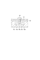
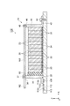
図1は、第1実施形態に係る電池パックを模式的に示す断面図である。図2は、図1の電池パックの一部を示す平面図である。図3は、図2のIII−III線に沿った電池パックの一部の断面図である。図4は、図1の電池パックの一部を示す平面図である。図1に示される電池パック10は、例えばフォークリフト等の産業車両のバッテリーとして使用され得る。電池パック10は、ベース12と、ベース12に取り付けられた電池モジュール14とを備える。
(First embodiment)
FIG. 1 is a cross-sectional view schematically showing the battery pack according to the first embodiment. FIG. 2 is a plan view showing a part of the battery pack of FIG. 3 is a partial cross-sectional view of the battery pack taken along line III-III in FIG. FIG. 4 is a plan view showing a part of the battery pack of FIG. The
ベース12は、電池モジュール14を収容する筐体の側壁であってもよいし、追加ウェイト又はカウンタウェイトとして機能し得る放熱部材であってもよい。ベース12は、例えば金属製の板状部材である。
The
電池モジュール14は、X軸方向に配列された複数の電池セル20と、電池セル20の配列方向(X軸方向)において電池セル20に拘束荷重を付加する第1のエンドプレート30及び第2のエンドプレート40とを備える。
The
電池セル20は、第1のエンドプレート30と第2のエンドプレート40との間に配置される。電池セル20は、例えばリチウムイオン二次電池などの非水電解質二次電池である。電池セル20は、例えば略直方体形状をなす中空のケースと、ケース内に収容された電極組立体とを備えている。ケースは、例えばアルミニウム等の金属によって形成されている。ケースの内部には、例えば有機溶媒系又は非水系の電解液が注入されている。電極組立体は、正極、負極、及び正極と負極との間に配置されたセパレータとによって構成されている。電極組立体では、例えば袋状のセパレータ内に正極が収容されており、正極が収容された袋状のセパレータと負極とが交互に積層されている。
The
エンドプレート30,40は、ベース12に取り付けられている。エンドプレート30,40は、例えばYZ平面に延在する金属製の板状部材である。エンドプレート30,40はそれぞれブラケット部32,42を有してもよい。ブラケット部32,42は、ベース12の表面に沿って延在する部分である。ブラケット部32,42はそれぞれエンドプレート30,40と別体でもよい。
The
各電池セル20とベース12との間には、例えば金属製の板状部材等の伝熱部材22が配置されてもよい。伝熱部材22は電池セル20に接続されている。各伝熱部材22とベース12との間には、例えば樹脂層等の弾性を有する伝熱層24が配置されてもよい。電池セル20において発生した熱は、伝熱部材22、伝熱層24及びベース12を経て放出される。X軸方向に配列される複数の伝熱層24に代えて、X軸方向に一体の伝熱シートを複数の伝熱部材22とベース12との間に配置してもよい。
A
エンドプレート30は、X軸方向において、エンドプレート30が受ける荷重に応じてベース12に対して可動である。エンドプレート30は、X軸方向にスライド可能である。エンドプレート30は、閾値以上の荷重を受けるとベース12に対して移動する一方、閾値未満の荷重を受ける場合にはベース12に対して移動しない。
The
エンドプレート40は、ベース12に固定されている。例えば、エンドプレート40のブラケット部42が例えば締結ボルト44等の締結部材によってベース12に固定される。エンドプレート40は、エンドプレート30と同様に、X軸方向において、エンドプレート40が受ける荷重に応じてベース12に対して可動であってもよい。
The
第1のエンドプレート30と第2のエンドプレート40とは、第2のエンドプレート40に固定された連結部60によって連結されてもよい。連結部60は、エンドプレート30,40の上端(ベース12側の端部とは反対側の端部)に取り付けられている。連結部60は、例えば金属製の板状部材である。連結部60の主面はベース12の表面に対向配置される。連結部60は、例えば複数の締結ボルト46等の締結部材によってエンドプレート40に固定されている。締結ボルト46はエンドプレート40の上端に設けられた穴部48に挿通される。連結部60はエンドプレート40と一体でもよい。この場合、締結ボルト46及び穴部48は不要になる。
The
第1実施形態において、エンドプレート30は、ベース12に取り付けられる第1の部分であるブラケット部32と、連結部60に取り付けられる第2の部分であるシャフト部36とを有する。ブラケット部32とシャフト部36は、エンドプレート30の本体部によって接続される。
In the first embodiment, the
ブラケット部32は、エンドプレート30の下端(ベース12側の端部)に設けられている。X軸方向において、エンドプレート30が受ける荷重に応じてブラケット部32はベース12に対して可動である。ブラケット部32はX軸方向に自由に移動できるが、Y軸方向及びZ軸方向におけるブラケット部32の移動は規制されている。
The
ブラケット部32には、ボルト34と、ボルト34の先端に螺合されたナット35とが固定されている。ボルト34の頭部はブラケット部32の上面(ベース12側の面とは反対側の面)に配置され、ナット35はブラケット部32の下面(ベース12側の面)に配置される。ナット35は、ベース12に設けられた穴部13内に収容されている。図2及び図3に示されるように、穴部13の入口周囲には庇部13aが設けられており、庇部13aの間に開口部13bが形成される。開口部13bは、穴部13と外部空間とを連通させる。開口部13bは、ベース12の表面においてX軸方向に延びている。開口部13bの幅(Y軸方向の寸法)は、ボルト34の軸部の径(Y軸方向の寸法)よりも大きく、ナット35の径(Y軸方向の寸法)よりも小さい。これにより、ブラケット部32はX軸方向にのみ移動できる。ナット35は抜け止め部として機能する。
A
シャフト部36は、エンドプレート30の上端に設けられ、エンドプレート30の延在方向(Z軸方向)に沿って突出している。シャフト部36は、例えば金属製の円柱状部材である。X方向において、エンドプレート30が受ける荷重に応じてシャフト部36は連結部60に対して可動である。エンドプレート30が閾値以上の荷重を受けると、シャフト部36が連結部60に対してX軸方向に移動する一方、エンドプレート30が閾値未満の荷重を受けてもシャフト部36は連結部60に対してX軸方向に移動しない。Y軸方向及びZ軸方向におけるシャフト部36の移動は規制されている。X軸方向において、シャフト部36の移動に伴ってブラケット部32も移動する。
The
第1実施形態において、シャフト部36は、X軸方向において多段階に可動である。すなわち、シャフト部36は、エンドプレート30が閾値以上の荷重を受けると、連結部60に対してX軸方向に移動して停止する。その後、エンドプレート30が閾値以上の荷重を受けると、再び連結部60に対してX軸方向に移動して停止する。シャフト部36はこのような動作を繰り返す。シャフト部36は、多段階ではなく1段階に可動であってもよい。
In the first embodiment, the
図1及び図4に示されるように、シャフト部36は連結部60に設けられた開口部62に挿通されている。開口部62は、Z軸方向から見て例えば矩形形状を有する。開口部62はX軸方向に延びている。開口部62のX軸方向に延びる各側壁には、複数の突起部64a,64b,64cが互いに離間して設けられている。各突起部64a,64b,64cは、例えばZ軸方向に延びる金属製の柱状部材である。XY平面における各突起部64a,64b,64cの断面は例えば台形である。一対の突起部64a,64aは、互いに対向配置される。一対の突起部64b,64bも互いに対向配置される。一対の突起部64c,64cも互いに対向配置される。X軸方向において、突起部64bは突起部64aと突起部64cとの間に配置され、突起部64aは、突起部64bとシャフト部36との間に配置される。シャフト部36は、一対の突起部64a,64aによって保持される。これにより、エンドプレート30,40が電池セル20に拘束荷重を付加することになる。よって、エンドプレート30からエンドプレート40まで到達する締結ボルトを用いて拘束荷重を付加する必要がない。そのような締結ボルトの代わりに連結部60が用いられている。シャフト部36は、エンドプレート30が閾値以上の荷重を受けると、一対の突起部64a,64a間を通り抜けて一対の突起部64b,64bに到達し、一対の突起部64b,64bによって保持される。その結果、エンドプレート30,40間の距離が大きくなるので、エンドプレート30,40間の拘束荷重は小さくなる。その後、再びエンドプレート30が閾値以上の荷重を受けると、シャフト部36は、一対の突起部64b,64b間を通り抜けて一対の突起部64c,64cに到達し、一対の突起部64c,64cによって保持される。その結果、エンドプレート30,40間の距離が大きくなるので、エンドプレート30,40間の拘束荷重は小さくなる。このように、シャフト部36及びエンドプレート30は、X軸方向において多段階に可動である。開口部62の各側壁に設けられる突起部64a,64b,64cの数及び高さ(Y軸方向の寸法)、突起部64a,64b,64c間の距離は、電池セル20の最大膨張量、弾性部材50を構成する材料の物性値、下限拘束荷重値(電池セル20の特性を担保するために必要な拘束荷重値)に基づいて決定され得る。連結部60は、一対の突起部64b,64b及び一対の突起部64c,64cを備えなくてもよい。この場合、シャフト部36は、多段階ではなく1段階に可動となる。
As shown in FIGS. 1 and 4, the
電池モジュール14は、エンドプレート30と電池セル20との間に配置された弾性部材50を備える。弾性部材50はエンドプレート40と電池セル20との間に配置されていない。ただし、弾性部材50がエンドプレート40と電池セル20との間にも更に配置されてもよい。弾性部材50は、電池セル20の配列方向における変動を吸収可能である。弾性部材50は、電池セル20に膨張が生じた場合等に、拘束荷重による電池セル20及びエンドプレート30,40の破損を防止する目的で用いられる部材である。弾性部材50は、例えばウレタン製のゴムスポンジによって矩形の板状に形成され、配列方向の一端側の電池セル20とエンドプレート30との間に配置されている。弾性部材50の他の形成材料としては、例えばエチレンプロピレンジエンゴム(EPDM)、クロロプレンゴム、シリコーンゴム等が挙げられる。また、弾性部材50は、ゴムに限られず、バネ材などであってもよい。
The
図5は、変形例に係る電池パックの一部を示す図である。図5(a)は、変形例に係る電池パックの一部を示す平面図であり、図5(b)は、図5(a)のVb−Vb線に沿った電池パックの一部の断面図である。図5に示されるように、ボルト34とナット35の組み合わせに代えて、ブラケット部32は、穴部13内に収容される抜け止め部135を備えてもよい。抜け止め部135は、ブラケット部32の本体部に軸部134により固定されている。軸部134及び抜け止め部135は、ベース12の表面に沿って延在する。軸部134及び抜け止め部135は、例えば金属製の板状部である。軸部134の幅(Y軸方向の寸法)は、開口部13bの幅(Y軸方向の寸法)よりも小さい。抜け止め部135の幅(Y軸方向の寸法)は、開口部13bの幅(Y軸方向の寸法)よりも大きい。これにより、ブラケット部32はX軸方向にのみ移動できる。
FIG. 5 is a diagram illustrating a part of a battery pack according to a modification. Fig.5 (a) is a top view which shows a part of battery pack which concerns on a modification, FIG.5 (b) is a cross section of a part of battery pack along the Vb-Vb line | wire of Fig.5 (a). FIG. As shown in FIG. 5, instead of the combination of the
図6は、他の変形例に係る電池パックの一部を示す平面図である。図6に示されるように、連結部60は、突起部64a,64b,64cに代えて突起部164を備えてもよい。突起部164は、開口部62のX軸方向に延びる各側壁に設けられる。一対の突起部164,164は互いに対向配置される。シャフト部36は、一対の突起部164,164によって保持される。これにより、エンドプレート30,40が電池セル20に拘束荷重を付加することになる。対向する突起部164,164間の間隔は、シャフト部36から離れるに連れて徐々に狭くなっている。各突起部164は、連結部60の本体部の剛性よりも小さい剛性を有している。各突起部164は、例えば弾性部材50と同様の材料からなる。そのため、シャフト部36は、エンドプレート30が第1閾値以上の荷重を受けると、突起部164,164の形状を変形させながら、突起部164,164間をシャフト部36から離れるようにX軸方向に移動する。これにより、エンドプレート30,40間の距離が大きくなるので、エンドプレート30,40間の拘束荷重は小さくなり、力が釣り合う場所でシャフト部36は停止する。その後、エンドプレート30が第1閾値よりも大きい第2閾値以上の荷重を受けると、シャフト部36は、突起部164,164の形状を変形させながら、突起部164,164間をシャフト部36から離れるようにX軸方向に移動する。これにより、エンドプレート30,40間の距離が大きくなるので、エンドプレート30,40間の拘束荷重は小さくなり、力が釣り合う場所でシャフト部36は停止する。このように、シャフト部36及びエンドプレート30は、X軸方向において多段階に可動である。シャフト部36は、エンドプレート30が第1閾値以上の荷重を受けた場合に、突起部164,164間をシャフト部36から離れるようにX軸方向に移動し、開口部62の端部まで到達して停止してもよい。この場合、シャフト部36は、多段階ではなく1段階に可動となる。
FIG. 6 is a plan view showing a part of a battery pack according to another modification. As shown in FIG. 6, the connecting
図7は、他の変形例に係る電池パックの一部を示す断面図である。図7に示されるように、電池モジュール14は、シャフト部36の先端に設けられた抜け止め部37を備えてもよい。抜け止め部37の幅(Y軸方向の寸法)は、開口部62の幅(Y軸方向の寸法)よりも大きい。抜け止め部37は、例えばシャフト部36の先端に螺合されるナットである。抜け止め部37によって、Z軸方向における連結部60の移動が規制される。このため、振動等によりシャフト部36が連結部60の開口部62から外れることを抑制できる。
FIG. 7 is a cross-sectional view showing a part of a battery pack according to another modification. As shown in FIG. 7, the
第1実施形態の電池パック10では、電池セル20の振動又は膨張に起因する電池セル20の変動を弾性部材50が吸収できる。よって、電池セル20の振動又は膨張に起因してエンドプレート30,40に加わる荷重を低減できる。さらに、エンドプレート30に荷重が加わると、電池セル20の配列方向にエンドプレート30が移動できる。そのため、エンドプレート30に過度な荷重が加わることを抑制できる。よって、エンドプレート30が変形したり破損したりすることを抑制できる。例えばエンドプレートが倒れるように変形すると、電池セル全体がベースから離れる方向(Z軸方向)に向かって反り、電池セルとベースとの間に隙間が形成されるおそれがある。そのような隙間が形成されると、放熱性が低下する。上記電池パック10では、そのような問題は生じ難い。
In the
エンドプレート40がベース12に固定されていると、エンドプレート40がベース12に対して可動である場合に比べて、エンドプレート40側に位置する電池セル20の変動が抑制される。また、両方のエンドプレートが可動であると、電池セル20がX軸方向に揺れ動くことになる。片方のエンドプレート40がベース12に固定されていると、そのような電池セル20の揺れ動きを抑制できる。さらに、エンドプレート40を可動にする必要がないので、電池パック10の構造をシンプルにできる。
When the
第1実施形態では、弾性部材50がエンドプレート30と電池セル20との間に配置される。よって、エンドプレート40側に位置する電池セル20の位置を固定できるので、エンドプレート40側の電池セル20の位置を基準として複数の電池セル20を配列する際に電池セル20の位置合わせが容易になる。また、弾性部材50がエンドプレート40と電池セル20との間に配置されると、電池セル20の両側に可動のエンドプレート30及び弾性部材50がそれぞれ配置されることによって、電池セル20がX軸方向に揺れ動くことになる。一方、弾性部材50がエンドプレート30と電池セル20との間に配置される場合、電池セル20の片側に可動のエンドプレート30及び弾性部材50が配置されるので、電池セル20がX軸方向に揺れ動き難くなる。
In the first embodiment, the
第1実施形態では、X軸方向において、エンドプレート30が受ける荷重に応じてエンドプレート30がベース12に対して多段階に可動である。よって、エンドプレート30がベース12に対して移動した後においても、エンドプレート30が受ける荷重に応じて再びエンドプレート30がベース12に対して移動できる。
In the first embodiment, in the X-axis direction, the
第1実施形態では、連結部60によってエンドプレート30,40が連結されており、エンドプレート30が、ベース12に取り付けられるブラケット部32と、連結部60に取り付けられるシャフト部36とを有する。さらに、X軸方向において、エンドプレート30が受ける荷重に応じて、ブラケット部32がベース12に対して可動であり、シャフト部36が連結部60に対して可動である。よって、エンドプレート30が複数個所で可動であるため、エンドプレート30が移動する際に傾き難くなる。そのため、エンドプレート30は電池セル20の配列方向に安定して移動できる。
In the first embodiment, the
第1実施形態では、X軸方向において、エンドプレート30が受ける荷重に応じてブラケット部32がベース12に対して自由に可動であり、エンドプレート30が受ける荷重に応じてシャフト部36が連結部60に対して多段階に可動である。この場合、シャフト部36の移動に伴ってブラケット部32も自由に移動できる。よって、エンドプレート30が移動する際に傾き難くなる。よって、エンドプレート30は電池セル20の配列方向に安定して移動できる。
In the first embodiment, the
(第2実施形態)
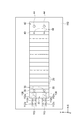
図8は、第2実施形態に係る電池パックを模式的に示す断面図である。図9及び図10は、図8の電池パックの一部を示す平面図である。図8に示される電池パック110は、例えばフォークリフト等の産業車両のバッテリーとして使用され得る。電池パック110は、シャフト部36がX軸方向に自由に可動であり、ブラケット部32がX軸方向において多段階に可動であること以外は、電池パック10と同様の構成を備える。電池パック110は、ベース12に代えてベース112を備え、連結部60に代えて連結部160を備える。また、シャフト部36の先端には抜け止め部37が設けられており、ブラケット部32は、ボルト34とナット35の組み合わせに代えてシャフト部136を備える。
(Second Embodiment)
FIG. 8 is a cross-sectional view schematically showing the battery pack according to the second embodiment. 9 and 10 are plan views showing a part of the battery pack of FIG. The
図8及び図9に示されるように、ブラケット部32は、シャフト部136を備える。シャフト部136は、ブラケット部32の下端(ベース12側の端部)に設けられ、Z軸方向に沿って突出している。シャフト部136は、例えば金属製の円柱状部材である。X方向において、エンドプレート30が受ける荷重に応じてシャフト部136はベース112に対して可動である。シャフト部136は、エンドプレート30が閾値以上の荷重を受けるとベース112に対してX軸方向に移動する一方、エンドプレート30が閾値未満の荷重を受けてもベース112に対してX軸方向に移動しない。Y軸方向及びZ軸方向におけるシャフト部136の移動は規制されている。
As shown in FIGS. 8 and 9, the
第2実施形態において、シャフト部136は、X軸方向において多段階に可動である。すなわち、シャフト部136は、エンドプレート30が閾値以上の荷重を受けると、ベース112に対してX軸方向に移動して停止する。その後、エンドプレート30が閾値以上の荷重を受けると、再びベース112に対してX軸方向に移動して停止する。シャフト部136はこのような動作を繰り返す。シャフト部136は、多段階ではなく1段階に可動であってもよい。
In the second embodiment, the
図8及び図9に示されるように、シャフト部136はベース112に設けられた穴部113内に挿通されている。穴部113は、Z軸方向から見て例えば矩形形状を有する。穴部113はX軸方向に延びている。穴部113のX軸方向に延びる各側壁には、複数の突起部112a,112b,112cが互いに離間して設けられている。各突起部112a,112b,112cは、例えばZ軸方向に延びる金属製の柱状部材である。XY平面における各突起部112a,112b,112cの断面は例えば台形である。一対の突起部112a,112aは、互いに対向配置される。一対の突起部112b,112bも互いに対向配置される。一対の突起部112c,112cも互いに対向配置される。X軸方向において、突起部112bは突起部112aと突起部112cとの間に配置され、突起部112aは、突起部112bとシャフト部136との間に配置される。シャフト部136は、一対の突起部112a,112aによって保持される。これにより、エンドプレート30,40が電池セル20に拘束荷重を付加することになる。シャフト部136は、エンドプレート30が閾値以上の荷重を受けると、一対の突起部112a,112a間を通り抜けて一対の突起部112b,112bに到達し、一対の突起部112b,112bによって保持される。その結果、エンドプレート30,40間の距離が大きくなるので、エンドプレート30,40間の拘束荷重は小さくなる。その後、再びエンドプレート30が閾値以上の荷重を受けると、シャフト部136は、一対の突起部112b,112b間を通り抜けて一対の突起部112c,112cに到達し、一対の突起部112c,112cによって保持される。その結果、エンドプレート30,40間の距離が大きくなるので、エンドプレート30,40間の拘束荷重は小さくなる。このように、シャフト部136及びエンドプレート30は、X軸方向において多段階に可動である。ベース112は、一対の突起部112b,112b及び一対の突起部112c,112cを備えなくてもよい。この場合、シャフト部136は、多段階ではなく1段階に可動となる。
As shown in FIGS. 8 and 9, the
図8及び図10に示されるように、シャフト部36は、連結部160に設けられた開口部162内に挿通されている。開口部162は、X軸方向に延びている。開口部162の幅(Y軸方向の寸法)は、シャフト部36の径(Y軸方向の寸法)よりも大きく、抜け止め部37の径(Y軸方向の寸法)よりも小さい。これにより、シャフト部36はX軸方向にのみ移動できる。シャフト部36はX軸方向に自由に移動できるが、Y軸方向及びZ軸方向におけるシャフト部36の移動は規制されている。
As shown in FIGS. 8 and 10, the
第2実施形態においても、第1実施形態と同様の構成に基づく作用効果が得られる。 Also in the second embodiment, an operational effect based on the same configuration as in the first embodiment can be obtained.
(第3実施形態)
図11は、第3実施形態に係る電池パックを模式的に示す断面図である。図11に示される電池パック210は、例えばフォークリフト等の産業車両のバッテリーとして使用され得る。電池パック210は、弾性部材50の位置が異なること以外、電池パック10と同様の構成を備える。電池パック210の電池モジュール114では、弾性部材50がエンドプレート40と電池セル20との間に配置される。エンドプレート30と電池セル20との間に弾性部材50は配置されていない。
(Third embodiment)
FIG. 11 is a cross-sectional view schematically showing the battery pack according to the third embodiment. The
第3実施形態においても、第1実施形態と同様の構成に基づく作用効果が得られる。さらに、エンドプレート40側に位置する電池セル20が弾性部材50に向かって変位する一方、エンドプレート30が可動であるため、エンドプレート30側に位置する電池セル20はエンドプレート30に向かって変位する。よって、弾性部材50をエンドプレート30と電池セル20との間に配置する場合に比べて、電池セル20の変位量の最大値を小さくできる。弾性部材50をエンドプレート30と電池セル20との間に配置する場合、最もエンドプレート30側に位置する電池セル20の変位量が通常最大となる。一方、弾性部材50をエンドプレート40と電池セル20との間に配置する場合、最もエンドプレート30側に位置する電池セル20の変位量と、最もエンドプレート40側に位置する電池セル20の変位量のうちいずれかが通常最大となる。電池セル20の変位量の最大値が小さいと、伝熱部材22と伝熱層24との間の滑り量を小さくできる。その結果、放熱性の低下を抑制できる。
Also in the third embodiment, an operational effect based on the same configuration as in the first embodiment can be obtained. Further, the
(第4実施形態)
図12は、第4実施形態に係る電池パックを模式的に示す断面図である。図12に示される電池パック310は、例えばフォークリフト等の産業車両のバッテリーとして使用され得る。電池パック310は、追加の弾性部材70と、締結ボルト84によってベース12に固定された壁部材80と、を更に備えること以外は、電池パック10と同様の構成を備える。
(Fourth embodiment)
FIG. 12 is a cross-sectional view schematically showing the battery pack according to the fourth embodiment. The
電池パック310の電池モジュール214では、追加の弾性部材70と電池セル20との間にエンドプレート30が配置される。追加の弾性部材70は、例えば弾性部材50と同様の材料からなる。X軸方向における追加の弾性部材70の幅は、X軸方向における弾性部材50の幅よりも大きい。
In the battery module 214 of the
壁部材80は例えばエンドプレート30と同様の部材であってもよい。壁部材80がベース12と一体であってもよい。壁部材80は、電池モジュール214を収容する筐体の側壁であってもよい。壁部材80は、連結部60に固定されてもよい。
The
第4実施形態においても、第1実施形態と同様の構成に基づく作用効果が得られる。さらに、追加の弾性部材70によって、電池セル20の配列方向にエンドプレート30が移動する際の衝撃を吸収できる。よって、エンドプレート30の移動に伴う衝撃による電池パック310の不具合を抑制できる。
Also in the fourth embodiment, an operational effect based on the same configuration as in the first embodiment can be obtained. Further, the additional
以上、本発明の好適な実施形態について詳細に説明されたが、本発明は上記実施形態に限定されない。 As mentioned above, although preferred embodiment of this invention was described in detail, this invention is not limited to the said embodiment.
電池パック10において、ブラケット部32は、締結ボルト等によってベース12に固定されてもよい。この場合であっても、シャフト部36は、X軸方向において多段階に可動であるので、エンドプレート30は、X軸方向において、エンドプレート30が受ける荷重に応じてベース12に対して可動である。
In the
電池パック110において、シャフト部36は、連結部160に固定されてもよい。この場合であっても、ブラケット部32は、X軸方向において多段階に可動であるので、エンドプレート30は、X軸方向において、エンドプレート30が受ける荷重に応じてベース12に対して可動である。
In the
電池パック10,110,210,310の各構成要素は任意に組み合わせ得る。例えば、第1実施形態の電池パック10において、ブラケット部32が、図8に示されるように、ボルト34とナット35の組み合わせに代えてシャフト部136を備えてもよい。この場合、ベース12に代えてベース112が用いられることになる。また、図5〜図7に示される電池パック10の変形例は、電池パック210,310にも適用可能である。図5及び図6に示される電池パック10の変形例を電池パック110に適用する場合、図5の抜け止め部135は、電池パック110の抜け止め部37の代わりに使用できる。図6の突起部164は、電池パック110の突起部112a,112b,112cの代わりに使用できる。
Each component of the
また、電池パック10,110,210,310は弾性部材50を備えなくてもよい。
Further, the battery packs 10, 110, 210, and 310 may not include the
第1実施形態において、エンドプレート30は、X軸方向において、エンドプレート30が受ける荷重に応じてベース12に対して多段階に可動であってもよい。また、第2実施形態において、シャフト部36は、X軸方向において、シャフト部36が受ける荷重に応じて連結部160に対して多段階に可動であってもよい。
In the first embodiment, the
10,110,210,310…電池パック、12,112…ベース、14,114,214…電池モジュール、20…電池セル、30…第1のエンドプレート、32…ブラケット部(第1の部分)、36…シャフト部(第2の部分)、40…第2のエンドプレート、50…弾性部材、60,160…連結部、70…追加の弾性部材。 10, 110, 210, 310 ... battery pack, 12, 112 ... base, 14, 114, 214 ... battery module, 20 ... battery cell, 30 ... first end plate, 32 ... bracket part (first part), 36 ... shaft portion (second portion), 40 ... second end plate, 50 ... elastic member, 60, 160 ... connecting portion, 70 ... additional elastic member.
Claims (8)
前記ベースに取り付けられた電池モジュールと、
を備え、
前記電池モジュールは、
配列された複数の電池セルと、
前記複数の電池セルの配列方向において前記複数の電池セルに拘束荷重を付加する第1及び第2のエンドプレートと、
前記第1のエンドプレートと前記複数の電池セルとの間、及び、前記第2のエンドプレートと前記複数の電池セルとの間の少なくとも一方に配置された弾性部材と、
を備え、
前記第1及び第2のエンドプレートが前記ベースに取り付けられており、
前記複数の電池セルの配列方向において、前記第1のエンドプレートが受ける荷重に応じて前記第1のエンドプレートが前記ベースに対して可動である、電池パック。 Base and
A battery module attached to the base;
With
The battery module is
A plurality of battery cells arranged;
First and second end plates for applying a restraining load to the plurality of battery cells in the arrangement direction of the plurality of battery cells;
An elastic member disposed between the first end plate and the plurality of battery cells, and at least one of the second end plate and the plurality of battery cells;
With
The first and second end plates are attached to the base;
The battery pack, wherein the first end plate is movable with respect to the base in accordance with a load received by the first end plate in an arrangement direction of the plurality of battery cells.
前記追加の弾性部材と前記複数の電池セルとの間に、前記第1のエンドプレートが配置される、請求項1〜5のいずれか一項に記載の電池パック。 An additional elastic member;
The battery pack according to any one of claims 1 to 5, wherein the first end plate is disposed between the additional elastic member and the plurality of battery cells.
前記第1のエンドプレートが、前記ベースに取り付けられる第1の部分と、前記連結部に取り付けられる第2の部分と、を有し、
前記複数の電池セルの配列方向において、前記第1のエンドプレートが受ける荷重に応じて前記第1の部分が前記ベースに対して可動であり、
前記複数の電池セルの配列方向において、前記第1のエンドプレートが受ける荷重に応じて前記第2の部分が前記連結部に対して可動である、請求項1〜6のいずれか一項に記載の電池パック。 The first end plate and the second end plate are connected by a connecting portion fixed to the second end plate,
The first end plate has a first part attached to the base and a second part attached to the connecting part;
In the arrangement direction of the plurality of battery cells, the first portion is movable with respect to the base according to a load received by the first end plate,
The arrangement of the plurality of battery cells according to any one of claims 1 to 6, wherein the second portion is movable with respect to the connecting portion in accordance with a load received by the first end plate. Battery pack.
Priority Applications (1)
| Application Number | Priority Date | Filing Date | Title |
|---|---|---|---|
| JP2016082739A JP2017195018A (en) | 2016-04-18 | 2016-04-18 | Battery pack |
Applications Claiming Priority (1)
| Application Number | Priority Date | Filing Date | Title |
|---|---|---|---|
| JP2016082739A JP2017195018A (en) | 2016-04-18 | 2016-04-18 | Battery pack |
Publications (1)
| Publication Number | Publication Date |
|---|---|
| JP2017195018A true JP2017195018A (en) | 2017-10-26 |
Family
ID=60154952
Family Applications (1)
| Application Number | Title | Priority Date | Filing Date |
|---|---|---|---|
| JP2016082739A Pending JP2017195018A (en) | 2016-04-18 | 2016-04-18 | Battery pack |
Country Status (1)
| Country | Link |
|---|---|
| JP (1) | JP2017195018A (en) |
Cited By (8)
| Publication number | Priority date | Publication date | Assignee | Title |
|---|---|---|---|---|
| CN110027493A (en) * | 2018-01-12 | 2019-07-19 | 丰田自动车株式会社 | Electrical storage device and vehicle |
| WO2019230107A1 (en) * | 2018-05-29 | 2019-12-05 | 信越ポリマー株式会社 | Heat dissipation structure and battery |
| WO2019244882A1 (en) * | 2018-06-20 | 2019-12-26 | 信越ポリマー株式会社 | Heat dissipation structure, heat dissipation structure production method, and battery |
| WO2019244881A1 (en) * | 2018-06-20 | 2019-12-26 | 信越ポリマー株式会社 | Heat dissipating structure, method for manufacturing heat dissipating structure, and battery |
| WO2020026966A1 (en) * | 2018-07-31 | 2020-02-06 | 三洋電機株式会社 | Cell module fixing structure |
| WO2021039197A1 (en) * | 2019-08-29 | 2021-03-04 | 三洋電機株式会社 | Power supply device, electric vehicle using same, and power storage device |
| JP2021516429A (en) * | 2019-02-01 | 2021-07-01 | エルジー・ケム・リミテッド | Battery assembly containing battery cells capable of simultaneous application of mechanical pressurization and magnetic pressurization |
| US11522246B2 (en) | 2018-03-07 | 2022-12-06 | Lg Energy Solution, Ltd. | Battery module, battery pack including same battery module, and automobile including same battery pack |
-
2016
- 2016-04-18 JP JP2016082739A patent/JP2017195018A/en active Pending
Cited By (20)
| Publication number | Priority date | Publication date | Assignee | Title |
|---|---|---|---|---|
| JP2019125443A (en) * | 2018-01-12 | 2019-07-25 | トヨタ自動車株式会社 | Power storage device |
| CN110027493A (en) * | 2018-01-12 | 2019-07-19 | 丰田自动车株式会社 | Electrical storage device and vehicle |
| CN110027493B (en) * | 2018-01-12 | 2022-10-25 | 丰田自动车株式会社 | Power storage device and vehicle |
| US11923562B2 (en) | 2018-03-07 | 2024-03-05 | Lg Energy Solution, Ltd. | Battery module, battery pack including same battery module, and automobile including same battery pack |
| US11522246B2 (en) | 2018-03-07 | 2022-12-06 | Lg Energy Solution, Ltd. | Battery module, battery pack including same battery module, and automobile including same battery pack |
| WO2019230107A1 (en) * | 2018-05-29 | 2019-12-05 | 信越ポリマー株式会社 | Heat dissipation structure and battery |
| JP7074851B2 (en) | 2018-06-20 | 2022-05-24 | 信越ポリマー株式会社 | Heat dissipation structure, manufacturing method of heat dissipation structure and battery |
| WO2019244882A1 (en) * | 2018-06-20 | 2019-12-26 | 信越ポリマー株式会社 | Heat dissipation structure, heat dissipation structure production method, and battery |
| WO2019244881A1 (en) * | 2018-06-20 | 2019-12-26 | 信越ポリマー株式会社 | Heat dissipating structure, method for manufacturing heat dissipating structure, and battery |
| JPWO2019244882A1 (en) * | 2018-06-20 | 2021-07-26 | 信越ポリマー株式会社 | Heat dissipation structure, manufacturing method of heat dissipation structure and battery |
| WO2020026966A1 (en) * | 2018-07-31 | 2020-02-06 | 三洋電機株式会社 | Cell module fixing structure |
| EP3832751A4 (en) * | 2018-07-31 | 2021-10-13 | SANYO Electric Co., Ltd. | Cell module fixing structure |
| JPWO2020026966A1 (en) * | 2018-07-31 | 2021-08-02 | 三洋電機株式会社 | Fixed structure of battery module |
| CN112514148A (en) * | 2018-07-31 | 2021-03-16 | 三洋电机株式会社 | Fixing structure of battery module |
| JP7307069B2 (en) | 2018-07-31 | 2023-07-11 | 三洋電機株式会社 | Fixing structure of battery module |
| CN112514148B (en) * | 2018-07-31 | 2023-11-28 | 三洋电机株式会社 | Fixing structure of battery module |
| JP7139009B2 (en) | 2019-02-01 | 2022-09-20 | エルジー エナジー ソリューション リミテッド | Battery assembly including battery cells capable of simultaneous application of mechanical pressure and magnetic pressure |
| JP2021516429A (en) * | 2019-02-01 | 2021-07-01 | エルジー・ケム・リミテッド | Battery assembly containing battery cells capable of simultaneous application of mechanical pressurization and magnetic pressurization |
| CN114175373A (en) * | 2019-08-29 | 2022-03-11 | 三洋电机株式会社 | Power supply device, and electrically powered vehicle and power storage device using same |
| WO2021039197A1 (en) * | 2019-08-29 | 2021-03-04 | 三洋電機株式会社 | Power supply device, electric vehicle using same, and power storage device |
Similar Documents
| Publication | Publication Date | Title |
|---|---|---|
| JP2017195018A (en) | Battery pack | |
| WO2020004039A1 (en) | Cushioning sheet for battery module | |
| JP5216068B2 (en) | Secondary battery | |
| EP3401976B1 (en) | Battery pack | |
| JP6390721B2 (en) | Battery pack | |
| JP2017103158A (en) | Battery pack | |
| JP6794709B2 (en) | Battery module | |
| WO2020235279A1 (en) | Bus bar plate | |
| JP6819159B2 (en) | Battery module | |
| JP6855789B2 (en) | Battery module | |
| JP6620655B2 (en) | Battery module | |
| JP6390722B2 (en) | Battery pack | |
| JP6759571B2 (en) | Battery pack | |
| JP5958376B2 (en) | Battery pack | |
| JP6597301B2 (en) | Battery module fixing structure | |
| JP6801208B2 (en) | Battery module | |
| JP2017147075A (en) | Method for manufacturing battery module, harness unit, and battery module | |
| JP6693334B2 (en) | Battery module | |
| JP2021064529A (en) | Battery pack | |
| US20230104750A1 (en) | Battery pack | |
| JP6874466B2 (en) | Battery pack | |
| JP7147535B2 (en) | battery pack | |
| JP2007022329A (en) | Supporting structure of power supply unit | |
| KR20230157648A (en) | Lighrweight and Rigid Battery Module Housing and Battery Pack Comprising the Same | |
| JP2018049697A (en) | Battery pack |