JP2017194128A - Coil spring, coil spring holding mechanism and image formation device - Google Patents
Coil spring, coil spring holding mechanism and image formation device Download PDFInfo
- Publication number
- JP2017194128A JP2017194128A JP2016085415A JP2016085415A JP2017194128A JP 2017194128 A JP2017194128 A JP 2017194128A JP 2016085415 A JP2016085415 A JP 2016085415A JP 2016085415 A JP2016085415 A JP 2016085415A JP 2017194128 A JP2017194128 A JP 2017194128A
- Authority
- JP
- Japan
- Prior art keywords
- coil spring
- central axis
- spring
- diameter
- end winding
- Prior art date
- Legal status (The legal status is an assumption and is not a legal conclusion. Google has not performed a legal analysis and makes no representation as to the accuracy of the status listed.)
- Granted
Links
Images


Classifications
-
- G—PHYSICS
- G03—PHOTOGRAPHY; CINEMATOGRAPHY; ANALOGOUS TECHNIQUES USING WAVES OTHER THAN OPTICAL WAVES; ELECTROGRAPHY; HOLOGRAPHY
- G03G—ELECTROGRAPHY; ELECTROPHOTOGRAPHY; MAGNETOGRAPHY
- G03G15/00—Apparatus for electrographic processes using a charge pattern
- G03G15/02—Apparatus for electrographic processes using a charge pattern for laying down a uniform charge, e.g. for sensitising; Corona discharge devices
- G03G15/0208—Apparatus for electrographic processes using a charge pattern for laying down a uniform charge, e.g. for sensitising; Corona discharge devices by contact, friction or induction, e.g. liquid charging apparatus
- G03G15/0216—Apparatus for electrographic processes using a charge pattern for laying down a uniform charge, e.g. for sensitising; Corona discharge devices by contact, friction or induction, e.g. liquid charging apparatus by bringing a charging member into contact with the member to be charged, e.g. roller, brush chargers
- G03G15/0233—Structure, details of the charging member, e.g. chemical composition, surface properties
-
- F—MECHANICAL ENGINEERING; LIGHTING; HEATING; WEAPONS; BLASTING
- F16—ENGINEERING ELEMENTS AND UNITS; GENERAL MEASURES FOR PRODUCING AND MAINTAINING EFFECTIVE FUNCTIONING OF MACHINES OR INSTALLATIONS; THERMAL INSULATION IN GENERAL
- F16F—SPRINGS; SHOCK-ABSORBERS; MEANS FOR DAMPING VIBRATION
- F16F1/00—Springs
- F16F1/02—Springs made of steel or other material having low internal friction; Wound, torsion, leaf, cup, ring or the like springs, the material of the spring not being relevant
- F16F1/04—Wound springs
- F16F1/047—Wound springs characterised by varying pitch
-
- F—MECHANICAL ENGINEERING; LIGHTING; HEATING; WEAPONS; BLASTING
- F16—ENGINEERING ELEMENTS AND UNITS; GENERAL MEASURES FOR PRODUCING AND MAINTAINING EFFECTIVE FUNCTIONING OF MACHINES OR INSTALLATIONS; THERMAL INSULATION IN GENERAL
- F16F—SPRINGS; SHOCK-ABSORBERS; MEANS FOR DAMPING VIBRATION
- F16F1/00—Springs
- F16F1/02—Springs made of steel or other material having low internal friction; Wound, torsion, leaf, cup, ring or the like springs, the material of the spring not being relevant
- F16F1/04—Wound springs
- F16F1/06—Wound springs with turns lying in cylindrical surfaces
-
- F—MECHANICAL ENGINEERING; LIGHTING; HEATING; WEAPONS; BLASTING
- F16—ENGINEERING ELEMENTS AND UNITS; GENERAL MEASURES FOR PRODUCING AND MAINTAINING EFFECTIVE FUNCTIONING OF MACHINES OR INSTALLATIONS; THERMAL INSULATION IN GENERAL
- F16F—SPRINGS; SHOCK-ABSORBERS; MEANS FOR DAMPING VIBRATION
- F16F1/00—Springs
- F16F1/02—Springs made of steel or other material having low internal friction; Wound, torsion, leaf, cup, ring or the like springs, the material of the spring not being relevant
- F16F1/04—Wound springs
- F16F1/12—Attachments or mountings
- F16F1/123—Attachments or mountings characterised by the ends of the spring being specially adapted, e.g. to form an eye for engagement with a radial insert
-
- F—MECHANICAL ENGINEERING; LIGHTING; HEATING; WEAPONS; BLASTING
- F16—ENGINEERING ELEMENTS AND UNITS; GENERAL MEASURES FOR PRODUCING AND MAINTAINING EFFECTIVE FUNCTIONING OF MACHINES OR INSTALLATIONS; THERMAL INSULATION IN GENERAL
- F16F—SPRINGS; SHOCK-ABSORBERS; MEANS FOR DAMPING VIBRATION
- F16F1/00—Springs
- F16F1/02—Springs made of steel or other material having low internal friction; Wound, torsion, leaf, cup, ring or the like springs, the material of the spring not being relevant
- F16F1/04—Wound springs
- F16F1/12—Attachments or mountings
- F16F1/125—Attachments or mountings where the end coils of the spring engage an axial insert
-
- F—MECHANICAL ENGINEERING; LIGHTING; HEATING; WEAPONS; BLASTING
- F16—ENGINEERING ELEMENTS AND UNITS; GENERAL MEASURES FOR PRODUCING AND MAINTAINING EFFECTIVE FUNCTIONING OF MACHINES OR INSTALLATIONS; THERMAL INSULATION IN GENERAL
- F16F—SPRINGS; SHOCK-ABSORBERS; MEANS FOR DAMPING VIBRATION
- F16F1/00—Springs
- F16F1/02—Springs made of steel or other material having low internal friction; Wound, torsion, leaf, cup, ring or the like springs, the material of the spring not being relevant
- F16F1/04—Wound springs
- F16F1/12—Attachments or mountings
- F16F1/128—Attachments or mountings with motion-limiting means, e.g. with a full-length guide element or ball joint connections; with protective outer cover
-
- G—PHYSICS
- G03—PHOTOGRAPHY; CINEMATOGRAPHY; ANALOGOUS TECHNIQUES USING WAVES OTHER THAN OPTICAL WAVES; ELECTROGRAPHY; HOLOGRAPHY
- G03G—ELECTROGRAPHY; ELECTROPHOTOGRAPHY; MAGNETOGRAPHY
- G03G15/00—Apparatus for electrographic processes using a charge pattern
- G03G15/02—Apparatus for electrographic processes using a charge pattern for laying down a uniform charge, e.g. for sensitising; Corona discharge devices
- G03G15/0283—Arrangements for supplying power to the sensitising device
-
- F—MECHANICAL ENGINEERING; LIGHTING; HEATING; WEAPONS; BLASTING
- F16—ENGINEERING ELEMENTS AND UNITS; GENERAL MEASURES FOR PRODUCING AND MAINTAINING EFFECTIVE FUNCTIONING OF MACHINES OR INSTALLATIONS; THERMAL INSULATION IN GENERAL
- F16F—SPRINGS; SHOCK-ABSORBERS; MEANS FOR DAMPING VIBRATION
- F16F2232/00—Nature of movement
- F16F2232/08—Linear
-
- F—MECHANICAL ENGINEERING; LIGHTING; HEATING; WEAPONS; BLASTING
- F16—ENGINEERING ELEMENTS AND UNITS; GENERAL MEASURES FOR PRODUCING AND MAINTAINING EFFECTIVE FUNCTIONING OF MACHINES OR INSTALLATIONS; THERMAL INSULATION IN GENERAL
- F16F—SPRINGS; SHOCK-ABSORBERS; MEANS FOR DAMPING VIBRATION
- F16F2238/00—Type of springs or dampers
- F16F2238/02—Springs
- F16F2238/026—Springs wound- or coil-like
Abstract
Description
本発明は、コイルばね、コイルばね保持機構及び画像形成装置に関する。 The present invention relates to a coil spring, a coil spring holding mechanism, and an image forming apparatus.
プリンタやコピー機をはじめとする画像形成装置や、自動車のサスペンションなどの機械装置の可動部にコイルばねを用いる構成が広く知られている(例えば特許文献1〜3等参照)。
かかるコイルばねを保持するための構造として、コイルばねの中心軸に挿入部を挿入して一体化することで保持するコイルばね保持機構が知られている。
このような従来のコイルばね保持機構においては、コイルばねの内径を、挿入部の外径よりも小さくし、圧入する方法が一般的である。
しかしながら、例えば機器の小型化を目的として、小径のコイルばねを用いる際には、径が変形し難く、挿入部の圧入が困難であるという問題が生じてしまう。
2. Description of the Related Art A configuration in which a coil spring is used for a movable part of an image forming apparatus such as a printer or a copier, or a mechanical device such as an automobile suspension is widely known (see, for example,
As a structure for holding such a coil spring, there is known a coil spring holding mechanism that holds the coil spring by inserting and inserting an insertion portion into the central axis of the coil spring.
In such a conventional coil spring holding mechanism, a method in which the inner diameter of the coil spring is made smaller than the outer diameter of the insertion portion and press-fitted is common.
However, for example, when a small-diameter coil spring is used for the purpose of downsizing the device, there is a problem that the diameter is difficult to deform and press-fitting of the insertion portion is difficult.
本発明は、以上のような問題点に鑑みてなされたものであり、組み付け時の作業性が良好なコイルばねの提供を目的とする。 The present invention has been made in view of the above problems, and an object of the present invention is to provide a coil spring with good workability during assembly.
上述した課題を解決するため、本発明のコイルばねは、第1中心軸を中心軸として第1の径で形成された弾性部と、前記弾性部の一方の端部側に配置され、前記第1中心軸を所定のシフト量だけ平行移動した第2中心軸を中心軸として形成された座巻部123と、を有し、前記第1の径よりも小さく、前記第1の径から前記シフト量を除いた寸法よりも大きい一体化対象物を座巻部側から挿入して一体化する。
In order to solve the above-described problems, a coil spring according to the present invention is provided on an elastic part formed with a first diameter with a first central axis as a central axis, on one end side of the elastic part, and An end
本発明のコイルばねによれば、組み付け時の作業性が向上する。 According to the coil spring of the present invention, workability during assembly is improved.
以下、本発明の実施形態の一例を図面を用いて説明する。 Hereinafter, an example of an embodiment of the present invention will be described with reference to the drawings.
本発明にかかるコイルばね保持機構の一例であるスプリング保持構造10は、画像形成装置100内に配置されて用いられる。
A
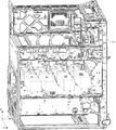
画像形成装置100は、図1に示すように、記録媒体としての用紙Pに画像を形成する、4つのプロセスユニット4Y、4C、4M、4BKを有する画像形成部4と、画像形成部4に用紙Pを供給する給紙装置3とを備えている。
画像形成装置100はまた、記録材たるトナーを収容するユニットであるトナーカートリッジ44と、原稿画像を読み取るスキャナとしての読取装置2と、を有している。
画像形成装置100はまた、筐体101内に、転写体たる無端状の中間転写ベルト47を備えた転写手段たる転写ユニット26と、画像形成部4の近傍に位置する露光手段としての光走査装置55とを有している。
画像形成装置100はまた、用紙Pを搬送し、中間転写ベルト47に担持されているトナー像を、中間転写ベルト47とのニップ部である2次転写位置Nでその用紙Pに転写する2次転写手段である転写搬送手段5を有している。
画像形成装置100はまた、2次転写後の中間転写ベルト47を清掃する中間転写ベルトクリーニング装置84を有している。
画像形成装置100はまた、給紙装置3から供給された用紙Pを所定のタイミングで2次転写位置Nに送り出すレジストローラ対45を有している。
画像形成装置100はまた、転写搬送手段5によって搬送され、2次転写位置Nを通過してトナー像を担持した用紙Pにそのトナー像を定着する定着ユニット6を有している。
画像形成装置100はまた、定着ユニット6を通過してトナー像を定着された用紙Pを外部に排出する排紙部7を有している。
画像形成装置100はまた、CPU並びに不揮発性メモリおよび揮発性メモリを搭載した、上記各部の動作を制御する制御手段としての画像形成制御部93を有している。
As shown in FIG. 1, the
The
The
The
The
The
The
The
The
読取装置2は、原稿に光を当ててその反射光をCCD(Charge Coupled Device)、またはCIS(Contact Image Sensor)などの読取センサで受光することによってRGB画像情報を読み取る。なお、RGB画像情報とは、用紙Pに形成される画像を表す情報であり、赤(R)、緑(G)、青(B)の各色の明度を含むものである。
The
給紙部3は、用紙Pを載置する給紙トレイ130と、給紙ローラ132と、を有している。
給紙ローラ132は、収納状態において、給紙トレイ130上に載置された用紙Pのうち、最上位の用紙Pに当接するように配置された円筒状のローラである。給紙ローラ132は、収納状態において回動して、給送ローラ131に向かって用紙Pを搬送する。
The paper feed unit 3 includes a
The
図1に示すように、プロセスユニット4Y、4C、4M、4BKはそれぞれ、図中時計方向であるA方向に回転する回転体としての像担持体たるドラム状の感光体40Y、40C、40M、40BKを有している。各感光体40Y、40C、40M、40BKはいずれも、その表面に光走査装置55が射出する走査光の被走査面である感光層が形成されている。
プロセスユニット4Y、4C、4M、4BKはまたそれぞれ、感光体40Y、40C、40M、40BKの周囲にA方向上流に設けられた、帯電装置43Y、43C、43M、43BKを有している。
プロセスユニット4Y、4C、4M、4BKはまたそれぞれ、現像手段としての現像装置42Y、42C、42M、42BKと、転写ユニット26に備えられた1次転写手段としての1次転写ローラ475Y、475C、475M、475BKとを有している。
プロセスユニット4Y、4C、4M、4BKはまたそれぞれ、感光体40Y、40C、40M、40BKの表面電位を検出する表面電位検知手段としての表面電位センサである電位センサを有している。
プロセスユニット4Y、4C、4M、4BKは、光走査装置55によって感光体40Y、40C、40M、40BKに潜像を形成することで、それぞれイエロー、シアン、マゼンタ、黒の各色のトナー像を形成する。
As shown in FIG. 1, each of the
The
The
Each of the
The
中間転写ベルト47は、駆動源によって図1中B方向に回転するように駆動される駆動ローラ471と、駆動ローラ471と同一方向に回転する従動ローラ472及び2次転写ローラ473とに巻きかけられている。
The
転写搬送手段5は、2次転写ローラ473に対向して設けられた2次転写対向ローラ474を有している。
転写搬送手段5は、2次転写位置Nにおいて、2次転写対向ローラ474が中間転写ベルト47に当接して、ニップ部を形成している。
転写搬送手段5は、2次転写位置Nにおいて、2次転写対向ローラ474と2次転写ローラ473との間に中間転写ベルト47を用紙Pとともに挟みこみ、2次転写バイアスをかけて中間転写ベルト47表面のトナー像を用紙Pに転写する。
このとき2次転写バイアスとしては、中間転写ベルト47の表面に帯電されている静電荷とは逆の電荷を付与する。
The transfer conveying unit 5 has a secondary
In the transfer conveyance unit 5, the secondary
At the secondary transfer position N, the transfer conveying means 5 sandwiches the
At this time, as the secondary transfer bias, a charge opposite to the electrostatic charge charged on the surface of the
定着ユニット6は、熱源を内部に有する加熱ローラ161と、加熱ローラ161とともに用紙Pを挟んで圧力を加える定着ローラ163とを有している。定着ローラ163は、加熱ローラ161に圧接し圧接部である定着部としての定着ニップを形成する。
定着ユニット6は、トナー像を担持した用紙Pを定着ニップに通すことで、熱と圧力との作用により、担持したトナー像を転写紙の表面に定着するようになっている。
加熱ローラ161は、アルミニウム製の円筒ローラと、円筒外周に形成されたシリコーンゴム層と、円筒内部に配設された発熱器としてのハロゲンヒータとを有している。
The fixing unit 6 includes a
The fixing unit 6 passes the paper P carrying the toner image through the fixing nip, thereby fixing the carried toner image on the surface of the transfer paper by the action of heat and pressure.
The
排紙部7は、対向して配設された1対の排紙ローラ171と、用紙Pの両面に画像を形成するために用紙Pの表裏を反転してレジストローラ対45まで搬送する両面ユニット173とを有している。
排紙部7はまた、表面、あるいは両面に画像を形成された用紙Pを排紙するため、画像形成部4と読取装置2との間に形成された空間である胴内排紙部74を有している。
画像形成装置100はここで、胴内排紙部74を有するいわゆる胴内排紙型の画像形成装置であるとしたが、画像形成装置100の外側の空間に用紙Pを排紙して積載する排紙トレイ方式を用いてもよい。
The paper discharge unit 7 is a pair of
The paper discharge unit 7 also includes an in-body
Here, the
画像形成制御部93は、CPU(Central Processing Unit)、メインメモリ(MEM−P)、ローカルメモリ(MEM−C)、HD(Hard Disk)、HDD(Hard Disk Drive)、PCIバス、ネットワークI/Fを有している。 The image forming control unit 93 includes a CPU (Central Processing Unit), a main memory (MEM-P), a local memory (MEM-C), an HD (Hard Disk), an HDD (Hard Disk Drive), a PCI bus, and a network I / F. have.
CPUは、メインメモリに記憶されたプログラムに従って、データを加工・演算したり、上述した各部の動作を制御したりするものである。メインメモリは画像形成制御部93の記憶領域としてはたらき、画像形成制御部93の各機能を実現させるプログラムやデータを記憶する。あるいはこのプログラムは、インストール可能な形式又は実行可能な形式のファイルでCD−ROM、FD、CD−R、DVD等のコンピュータで読み取り可能な記録媒体に記録して提供するように構成してもよい。 The CPU processes and calculates data according to a program stored in the main memory, and controls the operation of each unit described above. The main memory serves as a storage area for the image formation control unit 93 and stores programs and data for realizing the functions of the image formation control unit 93. Alternatively, this program may be configured to be provided by being recorded in a computer-readable recording medium such as a CD-ROM, FD, CD-R, DVD, etc. in an installable or executable format file. .
ローカルメモリ(MEM−C)は、コピー用画像バッファ及び符号バッファとして用いる。HDは、画像データの蓄積、印刷時に用いるフォントデータの蓄積、フォームの蓄積を行うためのストレージである。HDDは、CPUの制御にしたがってHDに対するデータの読み出し又は書き込みを制御する。ネットワークI/Fは、通信ネットワークを介して情報処理装置等の外部機器と情報を送受信する。 The local memory (MEM-C) is used as a copy image buffer and a code buffer. The HD is a storage for storing image data, storing font data used for printing, and storing forms. The HDD controls reading or writing of data with respect to the HD according to the control of the CPU. The network I / F transmits / receives information to / from an external device such as an information processing apparatus via a communication network.
画像形成制御部93は、通信ネットワークなどを介した上位装置(例えばパソコン)との双方向の通信を制御するための通信制御手段として動作する。
画像形成制御部93はまた、上位装置からの画像データを光走査装置55に送る画像データ処理手段としても動作する。
なお、これら機能については、詳細な説明を省略する。
The image formation control unit 93 operates as a communication control unit for controlling bidirectional communication with a host device (for example, a personal computer) via a communication network.
The image formation control unit 93 also operates as image data processing means for sending image data from the host device to the
Detailed descriptions of these functions are omitted.
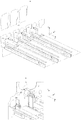
筐体101は、図2に示すように、プロセスユニット4Y、4C、4M、4BKが挿抜される位置に、帯電装置43Y、43C、43M、43BKに当接してバイアス電圧を印加するための給電経路を形成するためのスプリング保持構造10を有している。
スプリング保持構造10は、図3(a)に示すように、筐体101の−X方向側の壁部に一体化する態様で、電源部と帯電装置43Y、43C、43M、43BKとを接続して給電経路の一部を形成する接点としての機能を有している。図3(a)では帯電装置43Y、43C、43M、43BKを省略している。
なお、本実施形態においては、スプリング保持構造10を特に帯電装置43Y、43C、43M、43BKへの給電用途を目的として用いているが、かかる用途以外にも現像装置などの支持に用いても良いし、その他の部分に用いられても良い。
As shown in FIG. 2, the
As shown in FIG. 3A, the
In this embodiment, the
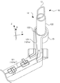
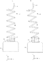
スプリング保持構造10は、図3(b)に示すように、保持部材の一部たるカバー11に覆われて、X方向に伸縮するスプリング12と、スプリング12の+X方向側の先端に取り付けられた先端部13と、を有している。
スプリング保持構造10は、先端部13の少なくとも一部が、帯電装置43Y、43C、43M、43BKの一部に当接した状態で−X方向へ押圧されることで、帯電装置43Y、43C、43M、43BKへ電力を供給する給電経路を形成する。
As shown in FIG. 3 (b), the
The
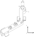
図4は、図3に示されたスプリング保持構造10について、カバー11を取り外した状態を示している。
スプリング保持構造10は、図4に示すように、保持部材15と、スプリング12と、を有している。
スプリング12は、詳細については後述するが、略円筒形状のコイルばねであって、±X方向に直線的に伸縮する圧縮ばねとしての機能を有している。
スプリング12は、−X方向側の端部に、保持部材15に沿って、給電経路を形成するための足部121を有している。
足部121は、本実施形態では、保持部材15の+X側の面に当接して、−Z方向に向かって直線状に延びる直線部121aと、直線部121aから所定の角度θで傾斜した直線状の傾斜部121bとを有している。
FIG. 4 shows a state where the cover 11 is removed from the
As shown in FIG. 4, the
As will be described in detail later, the
The
In this embodiment, the
保持部材15は、図5に示すように、保持部材15のスプリング12と当接する側の面に一体に設けられ、スプリング12の中心部に挿入されて一体化して固定される一体化対象物たる凸部151を有している。
保持部材15は、筐体101に固定されて、スプリング12の少なくとも−X方向側の端部と足部121とを支持している。
凸部151は、十字状に+X方向に突出した突起部分であり、凸部151のうち最大部分の幅すなわち最大幅dgは、dg=3.7±0.1mmの精度で形成されている。
なお、本実施形態では凸部151は±Y方向に最大幅dg=3.7±0.1mmをもつ十字状の突起部であるとしたが、円柱状や半球状、あるいは多角形の突出部分であっても良い。
As shown in FIG. 5, the holding
The holding
The
In the present embodiment, the
スプリング12は、図4に示すように、ソレノイドコイル状に巻きつけられた圧縮ばねとしての機能を有する弾性部122と、弾性部122の−X方向側の端部に形成された座巻部123と、を有している。
弾性部122は、図6に示すようにX軸と平行な仮想的な中心軸たる第1中心軸Oに沿って、第1の径たる内径φ1=4±0.2mmで形成された圧縮ばねである。
座巻部123は、第1中心軸Oを−Y方向に平行移動した第2中心軸O’に沿って、第2の径たる内径φ2=4±0.2mmで形成されている、所謂座巻部分である。
第2中心軸O’は、YZ平面においてシフト量Δy=0.8mmだけ第1中心軸Oとずれた仮想的な軸である。
言い換えると、スプリング12は、コイルばねとして機能する本体部である弾性部122と、中心軸が弾性部122に対してシフトしたシフト部としての座巻部123と、を有している。ここでシフトとは、第1中心軸Oに対して直交するYZ平面における平行移動を示す。
As shown in FIG. 4, the
As shown in FIG. 6, the
The
The second central axis O ′ is a virtual axis shifted from the first central axis O by a shift amount Δy = 0.8 mm on the YZ plane.
In other words, the
かかる座巻部123と弾性部122とをX方向から見たときの形状を図6に示す。
図6に示したように、φ1=φ2=4mmであり、第1中心軸Oと第2中心軸O’とがシフト量Δyだけずれているとき、弾性部122と座巻部123とで囲まれた部分の幅寸法たる最小幅dtは、dt=3.2mmとなる。
かかる最小幅dtは、言い換えると第1の径φ1からシフト量Δyを除いた内内寸法である。また、かかる内内寸法については、公差±0.2mmを含んでいても良い。
また、本実施形態では、φ1=φ2=4mmとしたが、φ1≠φ2であっても良い。
その場合にも、φ1−Δy<dg<φ2を満たすことが望ましい。
FIG. 6 shows the shape of the
As shown in FIG. 6, when φ 1 = φ 2 = 4 mm and the first central axis O and the second central axis O ′ are shifted by a shift amount Δy, the
Such minimum width dt is inside the inner dimensions except the shift amount Δy from diameter phi 1 when the first turn. Further, the inner and inner dimensions may include a tolerance of ± 0.2 mm.
In the present embodiment, φ 1 = φ 2 = 4 mm, but φ 1 ≠ φ 2 may be used.
Even in that case, it is desirable to satisfy φ 1 −Δy <dg <φ 2 .
図7は、スプリング12と保持部材15とが一体化して保持された状態を、第1中心軸Oを通る平面に射影したときの模式図を示している。
弾性部122は、−X方向側の端部側に、図7に示すように、弾性部122を形成する鋼線が互いに密着して形成された密着巻き部分122aを有している。
ここで、密着巻き部分122aは、2巻き以上の密着巻きであることが望ましく、本実施形態では3巻きの密着巻き部122aが形成されている。
FIG. 7 shows a schematic diagram when the state in which the
As shown in FIG. 7, the
Here, it is desirable that the tightly wound
座巻部123は、第2中心軸O’を中心軸として2巻き以上の密着巻きで形成されている。
座巻部123の+X方向側の端部は、弾性部122と一体に結合され、−X方向側の端部は、足部121と一体に結合されている。
The
The end portion on the + X direction side of the
かかる構成のスプリング12が、保持部材15に取り付けられる際の動作について説明する。
The operation when the
図5で示したように、凸部151の最大幅dgは3.7mm±0.1mmであり、第1の径たる内径φ1=4mmよりも小さい。
そのため、凸部151は、図7に示すように、弾性部122の中心部に挿入することができる。
また、図6に既に示したように、凸部151の最大幅dgは、座巻部123と弾性部122とで囲まれた部分の幅である最小幅dtよりも大きい。
そのため、スプリング12の中心部に、凸部151を挿入しようとするときには、凸部151は、最小幅dtを押し広げながら圧入される態様で挿入される。
言い換えると凸部151がスプリング12に挿入されるときには、座巻部123の中心が、第1中心軸Oに一致するように変形するから、かかる変形に対する応力が、凸部151を挟み込む方向の力として生じる。
すなわち、スプリング12は、挿入された凸部151を弾性部122と座巻部123とで挟みこむことで一体化して固定する。
As shown in FIG. 5, the maximum width dg of the
Therefore, the
Further, as already shown in FIG. 6, the maximum width dg of the
Therefore, when the
In other words, when the
That is, the
ところで、従来の圧縮ばねの固定構造としては、例えば、圧縮ばねの内径dsを保持部材の挿入部の外径よりも小さくして圧入するような構成がある。
しかしながら、かかる構成においては、圧縮ばねを小径化すると変形に要する力も大きくなるという弊害があり、圧入作業が困難になる一因となっていた。
さらに、径寸法に対して公差幅が相対的に大きくなり、部品精度の要求も高くなってしまっていた。
Incidentally, as a conventional compression spring fixing structure, for example, there is a configuration in which the inner diameter ds of the compression spring is made smaller than the outer diameter of the insertion portion of the holding member for press-fitting.
However, in such a configuration, if the diameter of the compression spring is reduced, there is an adverse effect that the force required for deformation is increased, which is a cause of difficulty in press-fitting work.
Furthermore, the tolerance width has become relatively large with respect to the diameter dimension, and the demand for component accuracy has also increased.
本実施形態のように、弾性部122と座巻部123とのそれぞれの中心軸が異なる場合には、弾性部122の内径φ1を凸部151よりも小さくする制限がなくなり、dt<dgであれば、凸部151を弾性部122と座巻部123とで挟み込んで保持される。
またさらに、dt<dg<φ1との関係式を満たすとすれば、凸部151の最大幅dgが、弾性部122に容易に挿入されるから、より簡易に保持部材11とスプリング12とを一体化して固定することができる。
As in the present embodiment, when the respective central axes of the
Furthermore, if the relational expression dt <dg <φ 1 is satisfied, the maximum width dg of the
さらに、本実施形態では、座巻部123の内径φ2と弾性部122の内径φ1とが等しく、最小幅dtは、dt=φ1−Δyで与えられる。すなわち、本実施形態では、φ1−Δy<dg<φ2を満たしている。
かかる構成により、凸部151を容易に挿入しながらも、凸部151が弾性部122と座巻部123とで挟み込むようにして固定されるから、コイルばね本体を小径化しながらも、組み付け時の作業性が向上する。
Further, in the present embodiment, the inner diameter φ 2 of the
With such a configuration, while the
本実施形態では、スプリング12は、第1中心軸Oを中心軸として内径φ1で形成された弾性部122と、弾性部122の一方の端部側に配置され、第1中心軸Oをシフト量Δyだけ平行移動した第2中心軸O’を中心軸として形成された座巻部123と、を有している。
スプリング12は、第1の径φ1よりも小さく、第1の径φ1からシフト量Δyを除いた内内寸法たる最小幅dtよりも大きい凸部151を−X方向側から挿入されて、凸部151を挟み込むように一体化する。
かかる構成により、コイルばね本体を小径化しながらも、組み付け時の作業性が向上する。
In this embodiment, the
With this configuration, the workability during assembly is improved while the coil spring body is reduced in diameter.
また、本実施形態では、スプリング12は、座巻部123の弾性部122とは反対側の端部すなわち−X方向側の端部に、YZ平面上に、−Z方向に延伸された足部121を有している。
かかる構成において、足部121の延伸された方向は、第1中心軸Oと第2中心軸O’とを結ぶ方向、言い換えると平行移動の方向とは、直交していることが望ましい。
かかる構成により、凸部151の圧入時のスプリング12の変位が、足部121の傾きや撓みによって吸収されやすくなり、座巻部123が凸部151の挿入によって変位する方向に変形しやすくなって作業に要する力が減少する。
Further, in the present embodiment, the
In such a configuration, it is desirable that the extending direction of the
With this configuration, the displacement of the
また、本実施形態では、座巻部123は2巻き以上の密着巻きで形成されている。
さらに、弾性部122の−X方向の端部側が2巻き以上の密着巻きで形成されている。
Moreover, in this embodiment, the
Further, the end portion side in the −X direction of the
かかる構成について詳しく説明する。図8(a)には、座巻部123’が1巻きであって、弾性部122’に密着巻きがない場合について示している。
図8(a)に示すようなスプリング固定構造10を用いた場合には、構成が簡易になる一方で、スプリング12’をY方向またはZ方向に変形させるような外力がはたらくと、図8(b)のように容易に変形してしまうおそれがある。
このようにスプリング12’がYZ方向に倒れてしまうと、±X方向に力が伝わり難い状況となってしまう懸念があった。
This configuration will be described in detail. FIG. 8A shows a case where the
When the
If the spring 12 'falls in the YZ direction in this way, there is a concern that it is difficult to transmit the force in the ± X direction.
そこで、本実施形態のように、座巻部123と、弾性部122の少なくとも−X方向側の端部と、が何れも2巻き以上の密着巻きで形成されることで、複数の接点で支持する形になるので、YZ方向に変形しにくく、スプリング12の倒れが抑制される。
なお、本実施形態では、座巻部123と、弾性部122の少なくとも−X方向側の端部と、が何れも2巻き以上の密着巻きで形成されるとしたが、何れか1方が密着巻きであれば良い。
Therefore, as in the present embodiment, the
In the present embodiment, the
ただし、スプリング12の倒れは、凸部151と当接した部分で抑えることが望ましいので、座巻部123を2巻き以上の密着巻きとすることがより好ましい。
However, since it is desirable to suppress the collapse of the
以上本発明の好ましい実施の形態について説明したが、本発明はかかる特定の実施形態に限定されるものではなく、上述の説明で特に限定していない限り、特許請求の範囲に記載された本発明の趣旨の範囲内において、種々の変形・変更が可能である。 The preferred embodiments of the present invention have been described above. However, the present invention is not limited to the specific embodiments, and the present invention described in the claims is not specifically limited by the above description. Various modifications and changes are possible within the scope of the above.
例えば、上記実施形態において、スプリング保持構造10は、画像形成装置の給電経路の接点に用いるとしたが、かかる構成に限定されるものではなく、その他の機械部品として用いられるものであっても良い。
また、本実施形態では、特に偏心の方向たる平行移動の方向について、Y方向に移動させるとしたが、かかる構成に限定されるものではない。
For example, in the above-described embodiment, the
In the present embodiment, the direction of translation, particularly the direction of eccentricity, is moved in the Y direction. However, the present invention is not limited to this configuration.
本発明の実施の形態に記載された効果は、本発明から生じる最も好適な効果を列挙したに過ぎず、本発明による効果は、本発明の実施の形態に記載されたものに限定されるものではない。 The effects described in the embodiments of the present invention are only the most preferable effects resulting from the present invention, and the effects of the present invention are limited to those described in the embodiments of the present invention. is not.
10 コイルばね保持機構(スプリング保持構造)
11 保持部材(カバー)
12 コイルばね(スプリング)
15 保持部材
121 足部
122、122’ 弾性部
123、123’ 座巻部(シフト部)
151 一体化対象物(凸部)
dt 内内寸法
dg (一体化対象物の)最大幅
φ1 第1の径
φ2 第2の径
Δy シフト量
O 第1中心軸
O’ 第2中心軸
Y 平行移動の方向
10 Coil spring holding mechanism (spring holding structure)
11 Holding member (cover)
12 Coil spring
15
151 Integration object (convex part)
dt inner dimension dg (of the integration object) maximum width φ 1 first diameter φ 2 second diameter Δy shift amount O first central axis O ′ second central axis Y direction of translation
Claims (6)
前記第1の径よりも小さく、前記第1の径から前記シフト量を除いた寸法よりも大きい一体化対象物を前記座巻部側から挿入して一体化するコイルばね。 An elastic part formed with a first diameter with the first central axis as a central axis, and a second center arranged on one end side of the elastic part and translated in parallel by the predetermined shift amount on the first central axis An end winding portion formed with the axis as a central axis,
A coil spring in which an integrated object smaller than the first diameter and larger than a dimension obtained by removing the shift amount from the first diameter is inserted and integrated from the end winding portion side.
前記コイルばねは、前記座巻部の前記弾性部とは反対側の端部に、前記第2中心軸と直交する平面上に延伸された足部を有し、
前記平行移動の方向は、前記足部の延伸された方向と直交する方向であることを特徴とするコイルばね。 The coil spring according to claim 1,
The coil spring has a leg portion extending on a plane orthogonal to the second central axis at an end portion of the end winding portion opposite to the elastic portion,
The coil spring according to claim 1, wherein the direction of the parallel movement is a direction orthogonal to a direction in which the foot is extended.
前記座巻部は2巻き以上の密着巻きで形成されたことを特徴とするコイルばね。 The coil spring according to claim 1 or 2,
The coil spring is characterized in that the end winding portion is formed by two or more tight windings.
前記弾性部の前記一方の端部側が2巻き以上の密着巻きで形成されたことを特徴とするコイルばね。 The coil spring according to claim 3,
The coil spring, wherein the one end side of the elastic portion is formed by two or more tightly wound windings.
前記一体化対象物と一体に形成され、当該コイルばねを保持するための保持部材と、を有し、前記一体化対象物が前記弾性部と前記座巻部とに挟持されて一体化して保持されることを特徴とするコイルばね保持機構。 A coil spring according to any one of claims 1 to 4,
And a holding member for holding the coil spring, and the integrated object is sandwiched between the elastic part and the end winding part and integrally held. A coil spring holding mechanism.
Priority Applications (2)
| Application Number | Priority Date | Filing Date | Title |
|---|---|---|---|
| JP2016085415A JP6733281B2 (en) | 2016-04-21 | 2016-04-21 | Coil spring, coil spring holding mechanism, and image forming apparatus |
| US15/486,263 US10061222B2 (en) | 2016-04-21 | 2017-04-12 | Coil spring, coil spring holder, and image forming apparatus |
Applications Claiming Priority (1)
| Application Number | Priority Date | Filing Date | Title |
|---|---|---|---|
| JP2016085415A JP6733281B2 (en) | 2016-04-21 | 2016-04-21 | Coil spring, coil spring holding mechanism, and image forming apparatus |
Publications (2)
| Publication Number | Publication Date |
|---|---|
| JP2017194128A true JP2017194128A (en) | 2017-10-26 |
| JP6733281B2 JP6733281B2 (en) | 2020-07-29 |
Family
ID=60090182
Family Applications (1)
| Application Number | Title | Priority Date | Filing Date |
|---|---|---|---|
| JP2016085415A Active JP6733281B2 (en) | 2016-04-21 | 2016-04-21 | Coil spring, coil spring holding mechanism, and image forming apparatus |
Country Status (2)
| Country | Link |
|---|---|
| US (1) | US10061222B2 (en) |
| JP (1) | JP6733281B2 (en) |
Families Citing this family (1)
| Publication number | Priority date | Publication date | Assignee | Title |
|---|---|---|---|---|
| US10156775B2 (en) * | 2016-06-01 | 2018-12-18 | Eric Zimmermann | Extensible mobile recording device holder |
Citations (5)
| Publication number | Priority date | Publication date | Assignee | Title |
|---|---|---|---|---|
| JPS5831452U (en) * | 1981-08-27 | 1983-03-01 | シチズン時計株式会社 | tension coil spring |
| JPH0647744U (en) * | 1992-12-04 | 1994-06-28 | 株式会社村田製作所 | Spring fixing device |
| JP2004167626A (en) * | 2002-11-20 | 2004-06-17 | Oki Data Corp | Spring mounting device and printer with the device |
| JP2006037953A (en) * | 2004-07-28 | 2006-02-09 | Panasonic Refrigeration Devices Singapore Pte Ltd | Device and system for reducing noise for reciprocating compressor |
| JP2011058408A (en) * | 2009-09-09 | 2011-03-24 | Aisan Industry Co Ltd | Electronically-controlled throttle control device |
Family Cites Families (5)
| Publication number | Priority date | Publication date | Assignee | Title |
|---|---|---|---|---|
| JP3149702B2 (en) | 1994-10-05 | 2001-03-26 | トヨタ自動車株式会社 | Spring seat structure |
| US5503375A (en) * | 1994-11-09 | 1996-04-02 | Bal Seal Engineering Company, Inc. | Coil spring with ends adapted for coupling without welding |
| AU2003279006A1 (en) * | 2002-09-30 | 2004-04-23 | Bal Seal Engineering Co., Inc. | Canted coil springs various designs |
| JP4259315B2 (en) | 2003-03-18 | 2009-04-30 | 株式会社デンソー | Electronically controlled throttle control device |
| JP2014235267A (en) | 2013-05-31 | 2014-12-15 | 株式会社リコー | Image forming apparatus |
-
2016
- 2016-04-21 JP JP2016085415A patent/JP6733281B2/en active Active
-
2017
- 2017-04-12 US US15/486,263 patent/US10061222B2/en active Active
Patent Citations (5)
| Publication number | Priority date | Publication date | Assignee | Title |
|---|---|---|---|---|
| JPS5831452U (en) * | 1981-08-27 | 1983-03-01 | シチズン時計株式会社 | tension coil spring |
| JPH0647744U (en) * | 1992-12-04 | 1994-06-28 | 株式会社村田製作所 | Spring fixing device |
| JP2004167626A (en) * | 2002-11-20 | 2004-06-17 | Oki Data Corp | Spring mounting device and printer with the device |
| JP2006037953A (en) * | 2004-07-28 | 2006-02-09 | Panasonic Refrigeration Devices Singapore Pte Ltd | Device and system for reducing noise for reciprocating compressor |
| JP2011058408A (en) * | 2009-09-09 | 2011-03-24 | Aisan Industry Co Ltd | Electronically-controlled throttle control device |
Also Published As
| Publication number | Publication date |
|---|---|
| US20170307996A1 (en) | 2017-10-26 |
| US10061222B2 (en) | 2018-08-28 |
| JP6733281B2 (en) | 2020-07-29 |
Similar Documents
| Publication | Publication Date | Title |
|---|---|---|
| JP2006091652A (en) | Cartridge, process cartridge and electrophotographic image forming apparatus | |
| US10606209B2 (en) | Housing and image forming apparatus | |
| JP2017167240A (en) | Process cartridge | |
| JP2006267243A (en) | Image forming apparatus and transfer device for use in the same | |
| JP4360141B2 (en) | Power supply device | |
| KR20140132611A (en) | Image forming apparatus | |
| JP2014133629A (en) | Sheet transfer device, image reader including the same, and image formation device including the same | |
| JP6733281B2 (en) | Coil spring, coil spring holding mechanism, and image forming apparatus | |
| JP2007079445A (en) | Belt unit and image forming apparatus | |
| JP4449922B2 (en) | Fixing device | |
| US9201384B2 (en) | Connection mechanism and image forming apparatus | |
| US8958731B2 (en) | Rotation shaft coupling structure, intermediate transfer unit including the same, and image forming apparatus | |
| US20160320744A1 (en) | Developing device insertion/extraction structure and image forming apparatus | |
| US20190181567A1 (en) | Electric connection structure and image forming apparatus | |
| JP4342883B2 (en) | Image forming apparatus | |
| JP4239097B2 (en) | Fixing device | |
| JP6922780B2 (en) | Image forming device | |
| JP2005025134A (en) | Photoreceptor drum, reinforcing member for photoreceptor drum, and image forming apparatus | |
| JP7484124B2 (en) | Fixing device and image forming apparatus | |
| JP5453216B2 (en) | Optical scanning device and image forming apparatus having the same | |
| JP6590168B2 (en) | Eccentric cam | |
| JP5853677B2 (en) | Scanning optical device | |
| JP6454963B2 (en) | Optical apparatus and image forming apparatus | |
| JP2007057625A (en) | Image recorder | |
| JP2021071537A (en) | Fixing device and image forming apparatus |
Legal Events
| Date | Code | Title | Description |
|---|---|---|---|
| A621 | Written request for application examination |
Free format text: JAPANESE INTERMEDIATE CODE: A621 Effective date: 20190208 |
|
| A977 | Report on retrieval |
Free format text: JAPANESE INTERMEDIATE CODE: A971007 Effective date: 20191210 |
|
| A131 | Notification of reasons for refusal |
Free format text: JAPANESE INTERMEDIATE CODE: A131 Effective date: 20191217 |
|
| A521 | Request for written amendment filed |
Free format text: JAPANESE INTERMEDIATE CODE: A523 Effective date: 20200207 |
|
| TRDD | Decision of grant or rejection written | ||
| A01 | Written decision to grant a patent or to grant a registration (utility model) |
Free format text: JAPANESE INTERMEDIATE CODE: A01 Effective date: 20200609 |
|
| A61 | First payment of annual fees (during grant procedure) |
Free format text: JAPANESE INTERMEDIATE CODE: A61 Effective date: 20200622 |
|
| R151 | Written notification of patent or utility model registration |
Ref document number: 6733281 Country of ref document: JP Free format text: JAPANESE INTERMEDIATE CODE: R151 |