JP2017194028A - Internal combustion engine device - Google Patents
Internal combustion engine device Download PDFInfo
- Publication number
- JP2017194028A JP2017194028A JP2016085407A JP2016085407A JP2017194028A JP 2017194028 A JP2017194028 A JP 2017194028A JP 2016085407 A JP2016085407 A JP 2016085407A JP 2016085407 A JP2016085407 A JP 2016085407A JP 2017194028 A JP2017194028 A JP 2017194028A
- Authority
- JP
- Japan
- Prior art keywords
- opening
- throttle
- engine
- torque
- request
- Prior art date
- Legal status (The legal status is an assumption and is not a legal conclusion. Google has not performed a legal analysis and makes no representation as to the accuracy of the status listed.)
- Granted
Links
Images


Classifications
-
- Y—GENERAL TAGGING OF NEW TECHNOLOGICAL DEVELOPMENTS; GENERAL TAGGING OF CROSS-SECTIONAL TECHNOLOGIES SPANNING OVER SEVERAL SECTIONS OF THE IPC; TECHNICAL SUBJECTS COVERED BY FORMER USPC CROSS-REFERENCE ART COLLECTIONS [XRACs] AND DIGESTS
- Y02—TECHNOLOGIES OR APPLICATIONS FOR MITIGATION OR ADAPTATION AGAINST CLIMATE CHANGE
- Y02T—CLIMATE CHANGE MITIGATION TECHNOLOGIES RELATED TO TRANSPORTATION
- Y02T10/00—Road transport of goods or passengers
- Y02T10/10—Internal combustion engine [ICE] based vehicles
- Y02T10/12—Improving ICE efficiencies
-
- Y—GENERAL TAGGING OF NEW TECHNOLOGICAL DEVELOPMENTS; GENERAL TAGGING OF CROSS-SECTIONAL TECHNOLOGIES SPANNING OVER SEVERAL SECTIONS OF THE IPC; TECHNICAL SUBJECTS COVERED BY FORMER USPC CROSS-REFERENCE ART COLLECTIONS [XRACs] AND DIGESTS
- Y02—TECHNOLOGIES OR APPLICATIONS FOR MITIGATION OR ADAPTATION AGAINST CLIMATE CHANGE
- Y02T—CLIMATE CHANGE MITIGATION TECHNOLOGIES RELATED TO TRANSPORTATION
- Y02T10/00—Road transport of goods or passengers
- Y02T10/60—Other road transportation technologies with climate change mitigation effect
- Y02T10/62—Hybrid vehicles
Landscapes
- Hybrid Electric Vehicles (AREA)
- Control Of Throttle Valves Provided In The Intake System Or In The Exhaust System (AREA)
- Output Control And Ontrol Of Special Type Engine (AREA)
- Electrical Control Of Air Or Fuel Supplied To Internal-Combustion Engine (AREA)
- Combined Controls Of Internal Combustion Engines (AREA)
Abstract
【課題】スロットルバルブが全開になる頻度を少なくする。【解決手段】トルク要求がスロットル全開要求であり、且つ、VVT進角要求があるときには、目標開度TH*を開度THmaxに設定し(S110,S120,S140)、トルク要求がスロットル全開要求でなかったり、VVT進角要求がないときには、吸入空気量Qaが要求トルクTe*に基づく目標空気量Qa*となるように目標スロットル開度TH*を設定し(S110〜S130)、スロットル開度THが目標スロットル開度TH*となるようにスロットルバルブの開度を調整するためのスロットルモータを駆動制御する。これにより、スロットルバルブが頻繁に全開となるのを抑制することができる。【選択図】図4To reduce the frequency at which a throttle valve is fully opened. When a torque request is a throttle full open request and a VVT advance request is made, a target opening TH * is set to an opening THmax (S110, S120, S140), and the torque request is a throttle full open request. If there is no VVT advance angle request, the target throttle opening TH * is set so that the intake air amount Qa becomes the target air amount Qa * based on the required torque Te * (S110 to S130), and the throttle opening TH The throttle motor for adjusting the opening of the throttle valve is driven and controlled so that becomes the target throttle opening TH *. Thereby, it can suppress that a throttle valve is fully opened frequently. [Selection] Figure 4
Description
本発明は、内燃機関装置に関し、詳しくは、可変バルブタイミング機構を有する内燃機関を備える内燃機関装置に関する。 The present invention relates to an internal combustion engine device, and more particularly to an internal combustion engine device including an internal combustion engine having a variable valve timing mechanism.
従来、この種の内燃機関装置としては、内燃機関に要求される要求トルクが内燃機関から出力可能な最大トルク以上であるときには、スロットルバルブ(スロットル弁)が全開になるように内燃機関を制御するものが提案されている(例えば、特許文献1参照)。この装置では、こうした制御により、スロットルバルブ(スロットル弁)の個体差や経時変化によらずに、内燃機関から最大トルクを出力している。 Conventionally, this type of internal combustion engine device controls the internal combustion engine so that the throttle valve (throttle valve) is fully opened when the required torque required for the internal combustion engine is equal to or greater than the maximum torque that can be output from the internal combustion engine. The thing is proposed (for example, refer patent document 1). With this control, the maximum torque is output from the internal combustion engine regardless of individual differences of the throttle valves (throttle valves) and changes with time.
ところで、吸気バルブの開閉タイミングを変更する可変バルブタイミング機構を有する内燃機関を備える内燃機関装置では、吸気バルブの開閉タイミングが要求トルクに応じたタイミングとなるように可変バルブタイミング機構とスロットルバルブとを制御している。この装置では、要求トルクが最大トルク以上のときには、スロットルバルブが全開になるように内燃機関を制御することにより、要求トルクのわずかな変化によってスロットルバルブの開度が変化することを抑制している。ところで、内燃機関の要求パワーが増加すると、内燃機関の回転数を現在の回転数から目標回転数に向かって徐々に高くしながら、要求パワーを出力するように内燃機関を制御する。したがって、内燃機関の要求トルクは、内燃機関の回転数が目標回転数に至るまで過渡的に高くなる。このとき、要求トルクが最大トルク以上となると、スロットルバルブが全開となる。このように、要求パワーが増加すると、スロットルバルブが全開になることがあり、要求パワーが繰り返し増加すると、スロットルバルブが頻繁に全開になり、燃費の悪化が生じたり、空燃比荒れによるエミッションの悪化が生じてしまう。 By the way, in an internal combustion engine apparatus having an internal combustion engine having a variable valve timing mechanism for changing the opening / closing timing of the intake valve, the variable valve timing mechanism and the throttle valve are provided so that the opening / closing timing of the intake valve becomes a timing according to the required torque. I have control. In this device, when the required torque is equal to or greater than the maximum torque, the internal combustion engine is controlled so that the throttle valve is fully opened, thereby suppressing the throttle valve opening from changing due to a slight change in the required torque. . By the way, when the required power of the internal combustion engine increases, the internal combustion engine is controlled to output the required power while gradually increasing the rotational speed of the internal combustion engine from the current rotational speed toward the target rotational speed. Therefore, the required torque of the internal combustion engine becomes transiently high until the rotational speed of the internal combustion engine reaches the target rotational speed. At this time, when the required torque is equal to or greater than the maximum torque, the throttle valve is fully opened. In this way, when the required power increases, the throttle valve may be fully opened, and when the required power increases repeatedly, the throttle valve is frequently fully opened, resulting in deterioration of fuel consumption or emission deterioration due to air-fuel ratio roughening. Will occur.
本発明の内燃機関装置は、スロットルバルブが全開になる頻度を少なくすることを主目的とする。 The internal combustion engine device of the present invention is mainly intended to reduce the frequency with which the throttle valve is fully opened.
本発明の内燃機関装置は、上述の主目的を達成するために以下の手段を採った。 The internal combustion engine apparatus of the present invention employs the following means in order to achieve the main object described above.
本発明の内燃機関装置は、
吸気バルブの開閉タイミングを変更可能な可変バルブタイミング機構を有する内燃機関と、
スロットルバルブの開度が目標開度となるように前記内燃機関を制御する制御手段と、
を備える内燃機関装置であって、
前記制御手段は、要求トルクが前記内燃機関の回転数に基づく所定トルク以上である第1条件と、前記吸気バルブの開閉タイミングの進角を要求する進角要求がなされている第2条件と、の2つの条件が共に成立しているときには、前記目標開度を全開に設定し、前記2つの条件のうち1つが成立しないときには、前記目標開度を前記要求トルクに応じた開度に設定する、
ことを要旨とする。
The internal combustion engine device of the present invention is
An internal combustion engine having a variable valve timing mechanism capable of changing the opening and closing timing of the intake valve;
Control means for controlling the internal combustion engine so that the opening of the throttle valve becomes a target opening;
An internal combustion engine device comprising:
The control means includes a first condition in which the required torque is equal to or greater than a predetermined torque based on the rotational speed of the internal combustion engine, and a second condition in which an advance angle request is made to request an advance angle of the opening / closing timing of the intake valve; When both of the two conditions are satisfied, the target opening is set to be fully open, and when one of the two conditions is not satisfied, the target opening is set to an opening corresponding to the required torque. ,
This is the gist.
この本発明の内燃機関装置では、要求トルクが内燃機関の回転数に基づく所定トルク以上である第1条件と、吸気バルブの開閉タイミングの進角を要求する進角要求がなされている第2条件と、の2つの条件が共に成立しているときには、目標開度を全開に設定し、2つの条件のうち1つが成立しないときには、目標開度を要求トルクに応じた開度に設定する。これにより、要求トルクが所定トルクよりも大きいときに一律に目標開度が全開に設定されるものに比して、目標開度が全開に設定されてスロットルバルブの開度が全開となる頻度を少なくすることができる。ここで、「所定トルク」とは、内燃機関から出力可能なトルクの最大値としてもよいし、内燃機関から出力可能なトルクの最大値付近のトルク(例えば、最大値の95%のトルクなど)としてもよい。 In the internal combustion engine device of the present invention, a first condition in which the required torque is equal to or greater than a predetermined torque based on the rotational speed of the internal combustion engine and a second condition in which an advance angle request for requesting an advance angle of the opening / closing timing of the intake valve is made. When the two conditions are both satisfied, the target opening is set to be fully open, and when one of the two conditions is not satisfied, the target opening is set to an opening according to the required torque. As a result, the frequency at which the target opening is set to fully open and the throttle valve opening is fully opened is compared with the case where the target opening is uniformly set to fully open when the required torque is greater than the predetermined torque. Can be reduced. Here, the “predetermined torque” may be the maximum value of torque that can be output from the internal combustion engine, or torque near the maximum value of torque that can be output from the internal combustion engine (for example, torque that is 95% of the maximum value). It is good.
次に、本発明を実施するための形態を実施例を用いて説明する。 Next, the form for implementing this invention is demonstrated using an Example.
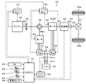
図1は、本発明の一実施例としてのハイブリッド自動車20の構成の概略を示す構成図である。実施例のハイブリッド自動車20は、図示するように、エンジン22と、プラネタリギヤ30と、モータMG1,MG2と、インバータ41,42と、変速機60と、バッテリ50と、ハイブリッド用電子制御ユニット(以下、「HVECU」という)70と、を備える。
FIG. 1 is a configuration diagram showing an outline of the configuration of a
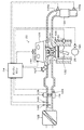
エンジン22は、ガソリンまたは軽油などの炭化水素系の燃料により動力を出力する内燃機関として構成されており、エンジン用電子制御ユニット(以下、エンジンECUという)24により燃料噴射制御や点火制御,吸入空気量調節制御などの運転制御を受けている。エンジン22は、図2に示すように、エアクリーナ122により清浄された空気をスロットルバルブ124を介して吸気管に吸入すると共に燃料噴射弁126からガソリンを噴射して吸入された空気とガソリンとを混合し、この混合気を吸気バルブ128を介して燃焼室129に吸入する。吸入した混合気は、点火プラグ130による電気火花によって爆発燃焼され、エンジン22は、そのエネルギにより押し下げられるピストン132の往復運動をクランクシャフト26の回転運動に変換する。エンジン22からの排気は、排気バルブ131を介して排気管へ送り出された後、一酸化炭素(CO)や炭化水素(HC),窒素酸化物(NOx)の有害成分を浄化する浄化触媒(三元触媒)を有する浄化装置134を介して外気へ排出される。エンジン22は、エンジン用電子制御ユニット(以下、「エンジンECU」という)24によって運転制御されている。
The
エンジンECU24は、図示しないCPUを中心とするマイクロプロセッサとして構成されており、CPUの他に、処理プログラムを記憶するROMやデータを一時的に記憶するRAM,入出力ポート,通信ポートを備える。 The engine ECU 24 is configured as a microprocessor centered on a CPU (not shown), and includes a ROM for storing a processing program, a RAM for temporarily storing data, an input / output port, and a communication port in addition to the CPU.
エンジンECU24には、エンジン22を運転制御するのに必要な各種センサからの信号が入力ポートを介して入力されている。各種センサからの信号の一部として、クランクシャフト26の回転位置を検出するクランクポジションセンサ140からのクランク角θcrやエンジン22の冷却水の温度を検出する水温センサ142からの冷却水温Tw,吸気バルブ128を開閉するインテークカムシャフトの回転位置および排気バルブ131を開閉するエキゾーストカムシャフトの回転位置を検出するカムポジションセンサ144からのカム角θci,θco,吸気管に設けられたスロットルバルブ124のポジションを検出するスロットルバルブポジションセンサ146からのスロットル開度TH,吸気管に取り付けられたエアフローメータ148からの吸入空気量Qa,排気管に取り付けられた空燃比センサ135aからの空燃比AF,排気管に取り付けられた酸素センサ135bからの酸素信号O2を挙げることができる。
Signals from various sensors necessary for controlling the operation of the
また、エンジンECU24からは、エンジン22を運転制御するための種々の制御信号が出力ポートを介して出力されている。種々の制御信号の一部として、スロットルバルブ124のポジションを調節するスロットルモータ136への駆動信号や燃料噴射弁126への駆動信号,点火プラグ130(イグニッションコイル)への制御信号,可変バルブタイミング機構138への制御信号を挙げることができる。
Various control signals for controlling the operation of the
エンジンECU24は、HVECU70と通信ポートを介して接続されている。エンジンECU24は、クランクポジションセンサ140からのクランク角θcrに基づいてエンジン22の回転数Neを演算している。また、エンジンECU24は、クランクポジションセンサ140からのクランク角θcrに対するカムポジションセンサ144からのインテークカムシャフトのカム角θciの角度(θci−θcr)に基づいて、吸気バルブ128の開閉タイミングVTを演算している。
The engine ECU 24 is connected to the HVECU 70 via a communication port. The engine ECU 24 calculates the rotational speed Ne of the
プラネタリギヤ30は、シングルピニオン式の遊星歯車機構として構成されている。プラネタリギヤ30のサンギヤには、モータMG1の回転子が接続されている。プラネタリギヤ30のリングギヤには、変速機60の入力軸61が接続されている。プラネタリギヤ30のキャリヤには、ダンパ28を介してエンジン22のクランクシャフト26が接続されている。
The
モータMG1は、例えば同期発電電動機として構成されており、上述したように、回転子がプラネタリギヤ30のサンギヤに接続されている。モータMG2は、例えば同期発電電動機として構成されており、回転子が変速機60の入力軸61に接続されている。インバータ41,42は、モータMG1,MG2を駆動するのに用いられ、電力ライン54を介してバッテリ50と接続されている。モータMG1,MG2は、モータ用電子制御ユニット(以下、「モータECU」という)40によって、インバータ41,42の図示しない複数のスイッチング素子がスイッチング制御されることにより、回転駆動される。
The motor MG1 is configured as, for example, a synchronous generator motor, and the rotor is connected to the sun gear of the
モータECU40は、図示しないが、CPUを中心とするマイクロプロセッサとして構成されており、CPUの他に、処理プログラムを記憶するROM,データを一時的に記憶するRAM,入出力ポート,通信ポートを備える。モータECU40には、モータMG1,MG2を駆動制御するのに必要な各種センサからの信号、例えば、モータMG1,MG2の回転子の回転位置を検出する回転位置検出センサ43,44からの回転位置θm1,θm2などが入力ポートを介して入力されている。モータECU40からは、インバータ41,42の図示しないスイッチング素子へのスイッチング制御信号などが出力ポートを介して出力されている。モータECU40は、HVECU70と通信ポートを介して接続されている。モータECU40は、回転位置検出センサからのモータMG1,MG2の回転子の回転位置θm1,θm2に基づいてモータMG1,MG2の回転数Nm1,Nm2を演算している。
Although not shown, the motor ECU 40 is configured as a microprocessor centered on a CPU, and includes a ROM for storing a processing program, a RAM for temporarily storing data, an input / output port, and a communication port in addition to the CPU. . The
変速機60は、4段変速機として構成されており、プラネタリギヤ30のリングギヤおよびモータMG2の回転子(回転軸)に接続された入力軸61と、駆動輪38a,38bにデファレンシャルギヤ37を介して連結された駆動軸36に接続された出力軸62と、複数の遊星歯車機構と、油圧駆動の複数の摩擦係合要素(クラッチ,ブレーキ)と、を有する。この変速機60は、入力軸61と出力軸62との間で4段階に変速して動力を伝達する。
The
バッテリ50は、リチウムイオン二次電池として構成されており、電力ライン54を介してインバータ41,42と接続されている。このバッテリ50は、バッテリ用電子制御ユニット(以下、「バッテリECU」という)52によって管理されている。
The battery 50 is configured as a lithium ion secondary battery, and is connected to the
バッテリECU52は、図示しないが、CPUを中心とするマイクロプロセッサとして構成されており、CPUの他に、処理プログラムを記憶するROM,データを一時的に記憶するRAM,入出力ポート,通信ポートを備える。バッテリECU52には、バッテリ50を管理するのに必要な各種センサからの信号、例えば、バッテリ50の端子間に取り付けられた電圧センサ51aからの電圧Vb,バッテリ50の出力端子に取り付けられた電流センサ51bからの電流Ibなどが入力ポートを介して入力されている。バッテリECU52は、HVECU70と通信ポートを介して接続されている。バッテリECU52は、電流センサ51bからの電流Ibの積算値や電圧Vbに基づいて蓄電割合SOCを演算している。
Although not shown, the
HVECU70は、図示しないが、CPUを中心とするマイクロプロセッサとして構成されており、CPUの他に、処理プログラムを記憶するROM,データを一時的に記憶するRAM,入出力ポート,通信ポートを備える。HVECU70には、各種センサからの信号が入力ポートを介して入力されている。HVECU70に入力される信号としては、例えば、駆動軸36(変速機60の出力軸62)に取り付けられた回転数センサ69からの駆動軸36の回転数Np,イグニッションスイッチ80からのイグニッション信号,シフトポジションセンサ82からのシフトポジションSPなどを挙げることができる。また、アクセルペダルポジションセンサ84からのアクセル開度Acc,ブレーキペダルポジションセンサ86からのブレーキペダルポジションBP,車速センサ88からの車速Vなども挙げることができる。HVECU70からは、変速機60への制御信号などが出力ポートを介して出力されている。HVECU70は、上述したように、エンジンECU24,モータECU40,バッテリECU52と通信ポートを介して接続されている。
Although not shown, the
こうして構成された実施例のハイブリッド自動車20では、ハイブリッド走行(HV走行)モードや電動走行(EV走行)モードで走行するようにエンジン22およびモータMG1,MG2(以下、「ハイブリッド部」という)と変速機60とを制御する。ここで、HV走行モードは、エンジン22の運転を伴って走行するモードであり、EV走行モードは、エンジン22の運転を伴わずに走行するモードである。以下、EV走行モードでのハイブリッド部の制御,HV走行モードでのハイブリッド部の制御,変速機60の制御について説明する。
In the
EV走行モードでのハイブリッド部の制御について説明する。HVECU70は、まず、アクセル開度Accと車速Vとに基づいて駆動軸36の要求トルクTout*を設定する。続いて、モータMG2の回転数Nm2(変速機60の入力軸61の回転数)を駆動軸36の回転数Noutで除して変速機60の減速比Grを計算し、駆動軸36の要求トルクTout*を変速機60の減速比Grで除して変速機60の入力軸61に要求される要求トルクTin*を計算する。そして、モータMG1のトルク指令Tm1*に値0を設定すると共に変速機60の入力軸61の要求トルクTin*をモータMG2のトルク指令Tm2*に設定し、設定したモータMG1,MG2のトルク指令Tm1*,Tm2*をモータECU40に送信する。モータECU40は、モータMG1,MG2がトルク指令Tm1*,Tm2*で駆動されるようにインバータ41,42の複数のスイッチング素子のスイッチング制御を行なう。
The control of the hybrid unit in the EV traveling mode will be described. First, the
HV走行モードでのハイブリッド部の制御について説明する。HVECU70は、まず、上述したのと同様に、駆動軸36(変速機60の出力軸62)の要求トルクTout*,変速機60の減速比Gr,変速機60の入力軸61の要求トルクTin*を設定する。続いて、変速機60の入力軸61の要求トルクTin*にモータMG2の回転数Nm2(変速機60の入力軸61の回転数)を乗じて変速機60の入力軸61に入力される要求パワーPin*を計算し、計算した要求パワーPin*からバッテリ50の蓄電割合SOCに基づく充放電要求パワーPb*(バッテリ50から放電するときが正の値)を減じてエンジン22に要求される要求パワーPe*を計算する。そして、要求パワーPe*とエンジン22の動作ライン(例えば燃費動作ライン)とを用いてエンジン22の仮目標回転数Netmpを設定する。図3は、エンジン22の動作ラインの一例と仮目標回転数Netmpを設定する様子を示す説明図である。図示するように、仮目標回転数Netmpは、動作ラインと要求パワーPe*(Netmp×Te)が一定の曲線との交点により求めることができる。こうして仮目標回転数Netmpを設定したら、エンジン22の回転数Neが現在の回転数Neから仮目標回転数Netmpに向かって動作ライン上を徐々に変化するように目標回転数Ne*を設定し、要求パワーPe*を目標回転数Ne*で除した値を要求トルクTe*に設定する。
The control of the hybrid unit in the HV traveling mode will be described. First, as described above, the
続いて、エンジン22の回転数Neが目標回転数Ne*となるようにするための回転数フィードバック制御によってモータMG1のトルク指令Tm1*を設定し、モータMG1をトルク指令Tm1*で駆動したときにモータMG1から出力されてプラネタリギヤ30を介して駆動軸36に作用するトルク(−Tm1*/ρ)を、変速機60の入力軸61の要求トルクTin*から減じて、モータMG2のトルク指令Tm2*を計算する。そして、エンジン22の目標回転数Ne*および要求トルクTe*をエンジンECU24に送信すると共にモータMG1,MG2のトルク指令Tm1*,Tm2*をモータECU40に送信する。エンジンECU24は、エンジン22が目標回転数Ne*および要求トルクTe*に基づいて運転されるようにエンジン22の吸入空気量制御や燃料噴射制御,点火制御,吸気バルブ128の開閉タイミング制御などを行なう。モータECU40は、モータMG1,MG2がトルク指令Tm1*,Tm2*で駆動されるようにインバータ41,42の複数のスイッチング素子のスイッチング制御を行なう。
Subsequently, when the torque command Tm1 * of the motor MG1 is set by the rotation speed feedback control so that the rotation speed Ne of the
ここで、エンジン22における制御について説明する。
Here, control in the
吸入空気量制御では、目標スロットル開度TH*を設定し、スロットル開度THが目標スロットル開度TH*となるようにスロットルモータ136を駆動制御する。目標スロットル開度TH*の設定については後述する。 In the intake air amount control, a target throttle opening TH * is set, and the throttle motor 136 is driven and controlled so that the throttle opening TH becomes the target throttle opening TH *. The setting of the target throttle opening TH * will be described later.
開閉タイミング制御では、基本的には、目標回転数Ne*および要求トルクTe*からなる運転ポイントでエンジン22を効率よく運転することができるように、吸気バルブ128の目標開閉タイミングVT*を設定し、吸気バルブ128の開閉タイミングVTが目標開閉タイミングVT*となるように可変バルブタイミング機構138を制御する。
In the opening / closing timing control, basically, the target opening / closing timing VT * of the
なお、燃料噴射制御および点火制御については本発明の中核をなさないことから、詳細な説明を省略する。 Since fuel injection control and ignition control do not form the core of the present invention, detailed description thereof is omitted.
変速機60の制御について説明する。HVECU70は、基本的には、アクセル開度Accと車速Vとに基づいて通常変速段Gsnoを設定し、この通常変速段Gsnoを目標変速段Gs*に設定し、変速機60の変速段Gsが目標変速段Gs*となるように変速機60を制御する。
The control of the
実施例のハイブリッド自動車20では、HVECU70は、可変バルブタイミング機構138の吸気バルブ128の開閉タイミングVTの進角を要求するためのVVT進角要求条件が成立したか否かを判定し、VVT進角要求条件が成立したときには、VVT進角要求をエンジンECU24に送信する。VVT進角要求条件は、エンジン22の要求パワーPeが、エンジン22に許容される最大回転数で出力可能な最大パワーを上回る第1進角条件と、変速機60の入力軸61の要求トルクTin*からモータMG2の最大定格トルクを減じたトルクが、エンジン22を動作ライン上の運転ポイントで運転したときに出力可能な最大パワーを上回る第2進角条件と、アクセル開度Accが第1開度(例えば、88%,90%,92%など)以上である第3進角条件と、の3つの条件のうちの少なくとも1つが成立したとき、すなわち、エンジン22に対して非常に大きなパワーやトルクの出力が要求されたときに成立する。VVT進角要求を受信したエンジンECU24は、吸気バルブ128の開閉タイミングが、目標回転数Ne*および要求トルクTe*からなる運転ポイントでエンジン22を効率よく運転できる開閉タイミングより早くなるように(進角するように)目標開閉タイミングVT*を設定して、吸気バルブ128の開閉タイミングVTが目標開閉タイミングVT*となるように可変バルブタイミング機構138を制御する。
In the
次に、こうして構成された実施例のハイブリッド自動車20の動作、特に、目標スロットル開度TH*を設定する際の動作について説明する。図4は、エンジンECU24により実行される目標開度設定ルーチンの一例を示すフローチャートである。本ルーチンは、所定時間毎(例えば、数msec毎)に実行される。
Next, the operation of the
本ルーチンが実行されると、エンジンECU24は、要求トルクTe*を入力する処理を実行する(ステップS100)。要求トルクTe*は、HVECU70により設定されたものを通信により入力している。
When this routine is executed, the
続いて、トルク要求がスロットル全開要求であるか否かを判定する(ステップS110)。この判定では、入力された要求トルクTe*がエンジン22の回転数Neに応じた最大トルクTemaxに所定割合k(例えば、0.93,0.95,0.97)を乗じた判定トルクTeth(=Temax・k)以上である第1条件と、エンジン22の点火タイミングを基準点火タイミングより遅くして変速ショックを低減するトルク低減制御を実行中ではない第2条件と、吸入空気量を制限する空気量制限を実行中ではない第3条件と、可変バルブタイミング機構138に異常が生じていない第4条件と、の4つの条件が成立したときに、トルク要求がスロットル全開要求であると判定する。最大トルクTemaxは、エンジン22の回転数Neが所定回転数未満の範囲では回転数Neが大きいときには小さいときに比して大きくなり、エンジン22の回転数Neが所定回転数以上の範囲では回転数Neが大きいときには小さいときに比して小さくなるように、変化する。
Subsequently, it is determined whether or not the torque request is a throttle full open request (step S110). In this determination, the input required torque Te * is determined by multiplying the maximum torque Temax according to the rotational speed Ne of the
トルク要求がスロットル全開要求ではないと判定されたときには、吸入空気量Qaが要求トルクTe*に基づく目標空気量Qa*となるように目標スロットル開度TH*を設定して(ステップS130)、本ルーチンを終了する。目標スロットル開度TH*を設定すると、スロットル開度THが目標スロットル開度TH*となるようにスロットルモータ136を駆動制御する。 When it is determined that the torque request is not a throttle full open request, the target throttle opening TH * is set so that the intake air amount Qa becomes the target air amount Qa * based on the required torque Te * (step S130). End the routine. When the target throttle opening TH * is set, the throttle motor 136 is driven and controlled so that the throttle opening TH becomes the target throttle opening TH *.
トルク要求がスロットル全開要求であるときには、さらに、VVT進角要求がなされているか否かを判定する(ステップS120)。この判定では、HVECU70からのVVT進角要求を受信しているときに、VVT進角要求がなされていると判定する。VVT進角要求がなされているときには、エンジン22に対して大きなパワーの出力が要求されていると判断して、目標スロットル開度TH*をスロットルバルブ124が全開となる開度THmaxに設定して(ステップS140)、本ルーチンを終了する。目標スロットル開度TH*を設定すると、スロットル開度THが目標スロットル開度TH*となるようにスロットルモータ136を駆動制御する。これにより、スロットルバルブ124を全開(例えば、全閉であるときのスロットルバルブ124の角度を0度としたときに85度,87度,89度など)にすることができ、エンジン22から出力するトルクを大きくすることができる。
If the torque request is a throttle full open request, it is further determined whether or not a VVT advance angle request has been made (step S120). In this determination, it is determined that the VVT advance angle request is made when the VVT advance angle request from the
VVT進角要求がなされていないときには、エンジン22に対してさほど大きなパワーの出力が要求されていないと判断して、吸入空気量Qaが要求トルクTe*に基づく目標空気量Qa*となるように目標スロットル開度TH*を設定して(ステップS130)、本ルーチンを終了する。こうして目標スロットル開度TH*を設定すると、スロットル開度THが目標スロットル開度TH*となるようにスロットルモータ136を駆動制御する。
When the VVT advance angle request is not made, it is determined that the
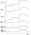
図5は、トルク要求がスロットル全開要求であると判定するための4つの条件のうち第2〜第4条件は成立しているときにおける、エンジン22の要求パワーPe*やエンジン22の回転数Ne,要求トルクTe*,VVT進角要求の有無,スロットル全開要求の有無の時間変化の一例を示す説明図である。図中、比較例として、VVT進角要求がなされているときに、一律に、目標スロットル開度TH*を開度THmaxに設定するものを記載している。エンジン22の要求パワーPe*が増加すると、エンジン22の回転数を現在の回転数Neから仮目標回転数Netmpに向けて徐々に高くするから、エンジン22の回転数Neが仮目標回転数Netmpに至るまでの期間、要求トルクTe*が過渡的に高くなり、最大トルクTemax以上となる場合がある。このとき、比較例では、VVT進角要求の有無に拘わらず、トルク要求がスロットル全開要求であると判定されるから、目標開度TH*が開度THmaxに設定され、スロットル開度THが全開となるようにスロットルモータ136が駆動制御される。さらに、要求パワーPe*が増加すると、より高い回転数に仮目標回転数Netmpが設定され、エンジン22の回転数を現在の回転数Neから仮目標回転数Netmpに向けて徐々に高くするから、エンジン22の回転数Neが仮目標回転数Netmpに至るまでの期間、要求トルクTe*が過渡的に高くなり、最大トルクTemax以上となって、スロットル開度THが全開となるようにスロットルモータ136が駆動制御される。このように、要求パワーPe*が繰り返し増加したり、増減が繰り返されると、スロットルバルブ124が頻繁に全開になり、燃費の悪化や空燃比荒れが生じる場合がある。実施例では、トルク要求がスロットル全開要求であり、且つ、VVT進角要求があるときには、目標開度TH*を開度THmaxに設定し、トルク要求がスロットル全開要求でなかったり、VVT進角要求がないときには、吸入空気量Qaが要求トルクTe*に基づく目標空気量Qa*となるように目標スロットル開度TH*を設定するから、目標開度TH*が頻繁に開度THmaxに設定されることを抑制できる。これにより、スロットルバルブ124が頻繁に全開となるのが抑制され、燃費の悪化や空燃比荒れを抑制することができる。
FIG. 5 shows the required power Pe * of the
以上説明した実施例のハイブリッド自動車20によれば、トルク要求がスロットル全開要求であり、且つ、VVT進角要求があるときには、目標開度TH*を開度THmaxに設定し、トルク要求がスロットル全開要求でなかったり、VVT進角要求がないときには、吸入空気量Qaが要求トルクTe*に基づく目標空気量Qa*となるように目標スロットル開度TH*を設定し、スロットル開度THが目標スロットル開度TH*となるようにスロットルモータ136を駆動制御することにより、目標開度TH*が頻繁に開度THmaxに設定されることを抑制できる。これにより、スロットルバルブ124が頻繁に全開となるのが抑制され、燃費の悪化や空燃比荒れを抑制することができる。
According to the
実施例のハイブリッド自動車20では、VVT進角要求条件は、第1進角条件〜第3進角条件のうちの少なくとも1つが成立したときに、成立しているが、第1進角条件〜第3進角条件のうちの1つのみが成立したときには、VVT進角要求条件が成立しているものとしてもよい。
In the
実施例のハイブリッド自動車20では、ステップS110の判定で、第1条件〜第4条件のうちの4つの条件が成立したときに、トルク要求がスロットル全開要求であると判定しているが、少なくとも、第1条件が成立したときにトルク要求がスロットル全開要求であると判定すればよいから、第1条件のみが成立したときにトルク要求がスロットル全開要求であると判定してもよい。
In the
実施例のハイブリッド自動車20では、トルク要求がスロットル全開要求であるか否かを判定するための第1条件を、入力された要求トルクTe*が最大トルクTemaxに所定割合kを乗じた判定トルクTeth以上である条件としているが、第1条件を入力された要求トルクTe*が最大トルクTemax以上である条件としてもよい。
In the
実施例では、本発明を、エンジン22とモータMG1,MG2を備えるハイブリッド自動車20に適用する場合を例示しているが、エンジンを備える装置であれば如何なる装置に適用してもよい。
In the embodiment, the case where the present invention is applied to the
実施例の主要な要素と課題を解決するための手段の欄に記載した発明の主要な要素との対応関係について説明する。実施例では、エンジン22が「内燃機関」に相当し、エンジンECU24とHVECU70とが「制御手段」に相当する。
The correspondence between the main elements of the embodiment and the main elements of the invention described in the column of means for solving the problems will be described. In the embodiment, the
なお、実施例の主要な要素と課題を解決するための手段の欄に記載した発明の主要な要素との対応関係は、実施例が課題を解決するための手段の欄に記載した発明を実施するための形態を具体的に説明するための一例であることから、課題を解決するための手段の欄に記載した発明の要素を限定するものではない。即ち、課題を解決するための手段の欄に記載した発明についての解釈はその欄の記載に基づいて行なわれるべきものであり、実施例は課題を解決するための手段の欄に記載した発明の具体的な一例に過ぎないものである。 The correspondence between the main elements of the embodiment and the main elements of the invention described in the column of means for solving the problem is the same as that of the embodiment described in the column of means for solving the problem. Therefore, the elements of the invention described in the column of means for solving the problems are not limited. That is, the interpretation of the invention described in the column of means for solving the problems should be made based on the description of the column, and the examples are those of the invention described in the column of means for solving the problems. It is only a specific example.
以上、本発明を実施するための形態について実施例を用いて説明したが、本発明はこうした実施例に何等限定されるものではなく、本発明の要旨を逸脱しない範囲内において、種々なる形態で実施し得ることは勿論である。 As mentioned above, although the form for implementing this invention was demonstrated using the Example, this invention is not limited at all to such an Example, In the range which does not deviate from the summary of this invention, it is with various forms. Of course, it can be implemented.
本発明は、内燃機関装置の製造産業などに利用可能である。 The present invention can be used in the manufacturing industry of internal combustion engine devices.
20 ハイブリッド自動車、22 エンジン、24 エンジン用電子制御ユニット(エンジンECU)、26 クランクシャフト、28 ダンパ、30 プラネタリギヤ、36 駆動軸、37 デファレンシャルギヤ、38a,38b 駆動輪、40 モータ用電子制御ユニット(モータECU)、41,42 インバータ、43,44 回転位置センサ、50 バッテリ、51a 電圧センサ、51b 電流センサ、52 バッテリ用電子制御ユニット(バッテリECU)、54 電力ライン、60 変速機、61 入力軸、62 出力軸、69 回転数センサ、70 ハイブリッド用電子制御ユニット(HVECU)、80 イグニッションスイッチ、82 シフトポジションセンサ、84 アクセルペダルポジションセンサ、86 ブレーキペダルポジションセンサ、88 車速センサ、122 エアクリーナ、124 スロットルバルブ、126 燃料噴射弁、128 吸気バルブ、129 燃焼室、130 点火プラグ、131 排気バルブ、132 ピストン、134 浄化装置、135a 空燃比センサ、135b 酸素センサ、136 スロットルモータ、138 可変バルブタイミング機構、140 クランクポジションセンサ、142 水温センサ、144 カムポジションセンサ、146 スロットルバルブポジションセンサ、148 エアフローメータ、149 温度センサ、MG1,MG2 モータ。 20 hybrid vehicle, 22 engine, 24 engine electronic control unit (engine ECU), 26 crankshaft, 28 damper, 30 planetary gear, 36 drive shaft, 37 differential gear, 38a, 38b drive wheel, 40 electronic control unit for motor (motor) ECU), 41, 42 inverter, 43, 44 rotational position sensor, 50 battery, 51a voltage sensor, 51b current sensor, 52 battery electronic control unit (battery ECU), 54 power line, 60 transmission, 61 input shaft, 62 Output shaft, 69 RPM sensor, 70 Hybrid electronic control unit (HVECU), 80 Ignition switch, 82 Shift position sensor, 84 Accel pedal position sensor, 86 Brake pedal position Sensor, 88 Vehicle speed sensor, 122 Air cleaner, 124 Throttle valve, 126 Fuel injection valve, 128 Intake valve, 129 Combustion chamber, 130 Spark plug, 131 Exhaust valve, 132 Piston, 134 Purifier, 135a Air-fuel ratio sensor, 135b Oxygen sensor, 136 throttle motor, 138 variable valve timing mechanism, 140 crank position sensor, 142 water temperature sensor, 144 cam position sensor, 146 throttle valve position sensor, 148 air flow meter, 149 temperature sensor, MG1, MG2 motor.
Claims (1)
スロットルバルブの開度が目標開度となるように前記内燃機関を制御する制御手段と、
を備える内燃機関装置であって、
前記制御手段は、要求トルクが前記内燃機関の回転数に基づく所定トルク以上である第1条件と、前記吸気バルブの開閉タイミングの進角を要求する進角要求がなされている第2条件と、の2つの条件が共に成立しているときには、前記目標開度を全開に設定し、前記2つの条件のうち1つが成立しないときには、前記目標開度を前記要求トルクに応じた開度に設定する、
内燃機関装置。 An internal combustion engine having a variable valve timing mechanism capable of changing the opening and closing timing of the intake valve;
Control means for controlling the internal combustion engine so that the opening of the throttle valve becomes a target opening;
An internal combustion engine device comprising:
The control means includes a first condition in which the required torque is equal to or greater than a predetermined torque based on the rotational speed of the internal combustion engine, and a second condition in which an advance angle request is made to request an advance angle of the opening / closing timing of the intake valve; When both of the two conditions are satisfied, the target opening is set to be fully open, and when one of the two conditions is not satisfied, the target opening is set to an opening corresponding to the required torque. ,
Internal combustion engine device.
Priority Applications (1)
| Application Number | Priority Date | Filing Date | Title |
|---|---|---|---|
| JP2016085407A JP6668912B2 (en) | 2016-04-21 | 2016-04-21 | Internal combustion engine device |
Applications Claiming Priority (1)
| Application Number | Priority Date | Filing Date | Title |
|---|---|---|---|
| JP2016085407A JP6668912B2 (en) | 2016-04-21 | 2016-04-21 | Internal combustion engine device |
Publications (2)
| Publication Number | Publication Date |
|---|---|
| JP2017194028A true JP2017194028A (en) | 2017-10-26 |
| JP6668912B2 JP6668912B2 (en) | 2020-03-18 |
Family
ID=60155979
Family Applications (1)
| Application Number | Title | Priority Date | Filing Date |
|---|---|---|---|
| JP2016085407A Active JP6668912B2 (en) | 2016-04-21 | 2016-04-21 | Internal combustion engine device |
Country Status (1)
| Country | Link |
|---|---|
| JP (1) | JP6668912B2 (en) |
Cited By (1)
| Publication number | Priority date | Publication date | Assignee | Title |
|---|---|---|---|---|
| CN109855355A (en) * | 2019-01-04 | 2019-06-07 | 广州美的华凌冰箱有限公司 | Refrigerator air door control method, controller, refrigerator, electronic equipment and storage medium |
Citations (2)
| Publication number | Priority date | Publication date | Assignee | Title |
|---|---|---|---|---|
| JPH09170462A (en) * | 1995-12-19 | 1997-06-30 | Isuzu Motors Ltd | Output control device for internal combustion engine |
| JP2001050052A (en) * | 1999-08-03 | 2001-02-23 | Fuji Heavy Ind Ltd | Engine intake control device |
-
2016
- 2016-04-21 JP JP2016085407A patent/JP6668912B2/en active Active
Patent Citations (2)
| Publication number | Priority date | Publication date | Assignee | Title |
|---|---|---|---|---|
| JPH09170462A (en) * | 1995-12-19 | 1997-06-30 | Isuzu Motors Ltd | Output control device for internal combustion engine |
| JP2001050052A (en) * | 1999-08-03 | 2001-02-23 | Fuji Heavy Ind Ltd | Engine intake control device |
Cited By (2)
| Publication number | Priority date | Publication date | Assignee | Title |
|---|---|---|---|---|
| CN109855355A (en) * | 2019-01-04 | 2019-06-07 | 广州美的华凌冰箱有限公司 | Refrigerator air door control method, controller, refrigerator, electronic equipment and storage medium |
| CN109855355B (en) * | 2019-01-04 | 2021-02-19 | 广州美的华凌冰箱有限公司 | Refrigerator air door control method, controller, refrigerator, electronic equipment and storage medium |
Also Published As
| Publication number | Publication date |
|---|---|
| JP6668912B2 (en) | 2020-03-18 |
Similar Documents
| Publication | Publication Date | Title |
|---|---|---|
| JP4867687B2 (en) | INTERNAL COMBUSTION ENGINE DEVICE, ITS CONTROL METHOD, AND VEHICLE | |
| JP6233328B2 (en) | Hybrid car | |
| JP5459333B2 (en) | Control device for hybrid vehicle | |
| CN108626005A (en) | hybrid vehicle | |
| JP4876953B2 (en) | Vehicle and control method thereof | |
| JP2016108998A (en) | Automobile | |
| JP5904131B2 (en) | Hybrid vehicle control device and hybrid vehicle | |
| JP4306719B2 (en) | INTERNAL COMBUSTION ENGINE DEVICE, POWER OUTPUT DEVICE EQUIPPED WITH THE SAME, VEHICLE MOUNTING THE SAME, METHOD FOR CONTROLLING INTERNAL COMBUSTION ENGINE DEVICE | |
| JP2010105626A (en) | Vehicle and control method therefor | |
| JP5991145B2 (en) | Hybrid car | |
| JP4241674B2 (en) | Hybrid vehicle and control method thereof | |
| JP6668912B2 (en) | Internal combustion engine device | |
| JP4222365B2 (en) | Internal combustion engine device and control method thereof | |
| JP2009274628A (en) | Hybrid vehicle and its control method | |
| JP6020281B2 (en) | vehicle | |
| JP5040833B2 (en) | Hybrid vehicle and control method thereof | |
| JP6277972B2 (en) | Hybrid car | |
| JP2012236548A (en) | Hybrid vehicle | |
| JP2012021414A (en) | Hybrid vehicle and control method of the same | |
| JP7226257B2 (en) | drive | |
| JP2008195134A (en) | POWER OUTPUT DEVICE, ITS CONTROL METHOD, AND VEHICLE | |
| JP2008126904A (en) | POWER OUTPUT DEVICE, VEHICLE MOUNTING THE SAME, AND METHOD FOR CONTROLLING POWER OUTPUT DEVICE | |
| JP2020001487A (en) | Hybrid vehicle | |
| JP2018094951A (en) | Hybrid vehicle | |
| JP2018039299A (en) | Hybrid automobile |
Legal Events
| Date | Code | Title | Description |
|---|---|---|---|
| A621 | Written request for application examination |
Free format text: JAPANESE INTERMEDIATE CODE: A621 Effective date: 20180524 |
|
| A977 | Report on retrieval |
Free format text: JAPANESE INTERMEDIATE CODE: A971007 Effective date: 20190221 |
|
| A131 | Notification of reasons for refusal |
Free format text: JAPANESE INTERMEDIATE CODE: A131 Effective date: 20190312 |
|
| A521 | Request for written amendment filed |
Free format text: JAPANESE INTERMEDIATE CODE: A821 Effective date: 20190417 |
|
| A131 | Notification of reasons for refusal |
Free format text: JAPANESE INTERMEDIATE CODE: A131 Effective date: 20190723 |
|
| A521 | Request for written amendment filed |
Free format text: JAPANESE INTERMEDIATE CODE: A523 Effective date: 20190919 |
|
| TRDD | Decision of grant or rejection written | ||
| A01 | Written decision to grant a patent or to grant a registration (utility model) |
Free format text: JAPANESE INTERMEDIATE CODE: A01 Effective date: 20200128 |
|
| A61 | First payment of annual fees (during grant procedure) |
Free format text: JAPANESE INTERMEDIATE CODE: A61 Effective date: 20200210 |
|
| R151 | Written notification of patent or utility model registration |
Ref document number: 6668912 Country of ref document: JP Free format text: JAPANESE INTERMEDIATE CODE: R151 |