JP2017193264A - Brake device control apparatus - Google Patents
Brake device control apparatus Download PDFInfo
- Publication number
- JP2017193264A JP2017193264A JP2016084976A JP2016084976A JP2017193264A JP 2017193264 A JP2017193264 A JP 2017193264A JP 2016084976 A JP2016084976 A JP 2016084976A JP 2016084976 A JP2016084976 A JP 2016084976A JP 2017193264 A JP2017193264 A JP 2017193264A
- Authority
- JP
- Japan
- Prior art keywords
- torque
- braking
- differential
- motor
- wheel
- Prior art date
- Legal status (The legal status is an assumption and is not a legal conclusion. Google has not performed a legal analysis and makes no representation as to the accuracy of the status listed.)
- Pending
Links
Images


Abstract
Description
この発明は、車輪への動力伝達経路内におけるいずれかの回転部材に制動トルクを作用させる制動装置の制御装置に関するものである。 The present invention relates to a control device for a braking device that applies a braking torque to any rotating member in a power transmission path to a wheel.
特許文献1には、運転者によって操作されるブレーキペダルと、電源と、その電源から供給される電力によって駆動されるモータと、そのモータによって駆動し、かつ車輪に制動力を作用させるブレーキとにより構成された電動式ブレーキ装置が記載されている。具体的には、モータに供給される電力とブレーキの制動トルクとの実際の関係を取得して適切にブレーキを制御するように構成されており、特に、摩擦材の摩擦係数の変動を推定して目標制動トルクとなるようにモータへ供給する電流を補正している。
運転者が要求する減速度ならびに車両運動を実現するためには、例えば、上記の特許文献1に記載されているように、モータへ供給される電力と実際の制動トルクとの関係から制動トルクを制御することが有効である。しかしながら、上記の実際の制動トルクは、摩擦材の変化については考慮しているものの、路面環境の変化については考慮されていない。したがって、そのような路面環境の変化等の外乱によっては、正確に上記の実際の制動トルクを把握することは困難である。そのため、実際の制動トルクと目標制動トルクとの偏差が大きい場合には正確に制動トルクを制御できなくなるばかりか、車両の走行安定性が低下し、ひいては、運転者に違和感をも与えるおそれがある。
In order to realize the deceleration and vehicle motion required by the driver, for example, as described in
この発明は上記の技術的課題に着目してなされたものであり、正確に制動トルクを制御することができる制動装置の制御装置を提供することを目的とするものである。 The present invention has been made by paying attention to the above technical problem, and an object of the present invention is to provide a braking device control device capable of accurately controlling braking torque.
上記の目的を達成するために、この発明は、駆動力源と、車輪と、前記駆動力源と前記車輪とを連結するドライブシャフトと、前記車輪への動力伝達経路に配置され、かつ前記ドライブシャフトの前記駆動力源側に設けられた回転部材と、前記回転部材に制動トルクを作用させる制動装置と、前記制動装置の制動トルクを制御するアクチュエータとを備えた制動装置の制御装置において、前記アクチュエータの制御量を制御するコントローラを備え、前記コントローラは、前記アクチュエータの制御量を所定の周波数で振動させ、前記アクチュエータの制御量を振動させた状態における前記回転部材の回転数を検出するとともに、その回転数が振動することによる振幅を求め、前記回転部材の回転数の前記振幅と、前記所定の周波数で振動させた制御量から推定される前記制動装置の振幅とに基づいて、前記アクチュエータの制御量と前記回転部材のトルクとの相関関係を求め、前記相関関係に基づいて、前記回転部材のトルクが目標制動トルクとなるように前記アクチュエータの制御量を制御するように構成されていることを特徴とするものである。 In order to achieve the above object, the present invention is arranged in a drive power source, a wheel, a drive shaft connecting the drive power source and the wheel, a power transmission path to the wheel, and the drive. In the control device for a braking device, comprising: a rotating member provided on the driving force source side of the shaft; a braking device that applies a braking torque to the rotating member; and an actuator that controls the braking torque of the braking device. A controller for controlling a control amount of the actuator, wherein the controller vibrates the control amount of the actuator at a predetermined frequency and detects the number of rotations of the rotating member in a state where the control amount of the actuator is vibrated; The amplitude obtained by the vibration of the number of rotations is obtained, and the amplitude of the number of rotations of the rotating member is oscillated at the predetermined frequency. The correlation between the control amount of the actuator and the torque of the rotating member is obtained based on the amplitude of the braking device estimated from the control amount, and the torque of the rotating member is determined as the target braking based on the correlation. The control amount of the actuator is controlled so as to be torque.
この発明によれば、アクチュエータの制御量を振動させ、その状態での回転部材の回転数の振幅と、所定の周波数で振動させた制御量から推定される制動装置の振幅との相関関係を求めて電流値を制御している。そのため、路面環境や、摩擦材の摩耗等の外乱があった場合でも、正確に制動トルクを出力することができる。したがって、運転者の意図する制動トルクを出力することができ、その結果、走行安定性を向上させることができる。また、このような簡単な構成によって意図した制動トルクを出力することができることにより、別途、他のセンサなどを搭載する必要がなく、コストの増大ならびに装置全体としての大型化を抑制することができる。 According to this invention, the control amount of the actuator is vibrated, and the correlation between the amplitude of the rotational speed of the rotating member in that state and the amplitude of the braking device estimated from the control amount vibrated at a predetermined frequency is obtained. To control the current value. Therefore, even when there is a disturbance such as a road surface environment or wear of the friction material, the braking torque can be output accurately. Therefore, the braking torque intended by the driver can be output, and as a result, traveling stability can be improved. Further, since the intended braking torque can be output with such a simple configuration, there is no need to separately install another sensor or the like, and an increase in cost and an increase in size of the entire apparatus can be suppressed. .
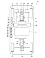
この発明で対象とすることのできる制御装置の構成例を図1および図2に模式的に示している。その制御装置は、図1に示すように駆動力源である駆動用モータ1a,1bと、その駆動用モータ1a,1bから出力されたトルクを左右の駆動輪2L,2R,3L,3Rに伝達する差動機構4a,4bと、左右の駆動輪2L,2R,3L,3Rに伝達するトルクの分配率を制御する差動用モータ5a,5bとにより構成されている。また、上記の差動機構4a(4b)と差動用モータ5a(5b)とによりトルクベクタリング装置を構成している。なお、図1では、電気的な接続関係を破線で示し、図2では、便宜上、図1の前輪2L,2R側(紙面上側)の駆動用モータ1aおよび差動機構4aならびに差動用モータ5aの構成を示している。
A configuration example of a control device that can be a subject of the present invention is schematically shown in FIGS. 1 and 2. As shown in FIG. 1, the control device transmits driving
図2に示す駆動用モータ1aは、従来知られているハイブリッド車両や電気自動車などに駆動力源として設けられているモータと同様に、例えば、永久磁石形同期モータで構成されている。すなわち、駆動用モータ1aに通電する電流値や、駆動用モータ1aに作用させる電圧を制御することにより、駆動トルクを出力することや制動トルクを出力することができるように構成されている。その駆動用モータ1aは、円筒状の第1ハウジング6の内面にステータ7が固定され、第1ハウジング6の中心軸線を中心として回転するようにロータ8が設けられている。また、第1ハウジング6における両端は、中心に貫通孔が形成された側壁部9,10により閉じられている。そして、上記ロータ8に出力軸11が一体化されている。
The
この出力軸11は、上記各貫通孔から外側に延出しており、一方の端部に出力ギヤ12が連結され、他方の端部に第1ハウジング6の外径よりも若干外径が小さい円盤状の第1回転体13が連結されている。図2に示す第1回転体13は、磁性材料により構成されており、駆動用モータ1aとは反対側を向いた側面に環状の凸部14が形成されている。上記各貫通孔の内周面には、ボールベアリング15,16が嵌合しており、出力軸11は、それらボールベアリング15,16に回転自在に保持されている。なお、上記の出力軸11や上記第1回転体13、ならびに、後述する出力軸53や上記第2回転体55が、この発明の実施例における『回転部材』に相当する。
The
また、図2に示す例では、第1回転体13の外径よりも内径が大きい有底円筒状の第1カバー部材17が設けられており、第1カバー部材17の開口部を閉じるように第1カバー部材17と第1ハウジング6とが一体化されている。第1カバー部材17と第1ハウジング6とに囲われた空間に、駆動用モータ1aの出力軸11の回転を停止させるための第1ブレーキ機構18aが設けられている。この第1ブレーキ機構18aは、第1回転体13と、第1回転体13のうち凸部14が形成された側面と対向した環状の第1押圧部材19と、第1押圧部材19を挟んで第1回転体13とは反対側に設けられた環状のプレート部材20と、そのプレート部材20を軸線方向に移動させるためのパーキング用モータ21とにより構成されている。
In the example shown in FIG. 2, a bottomed cylindrical
上述した第1押圧部材19は、外周面が第1カバー部材17の内周面とスプライン係合している。すなわち、第1押圧部材19は、第1カバー部材17の軸線方向に移動することができ、かつ回転することができないように設けられている。そして、第1押圧部材19の内周部は、第1回転体13の凸部14よりも内側まで形成されており、その内周部が第1回転体13側に突出している。そして、その突出した部分に、第1コイル22が巻き付けられている。
The first pressing
また、上記第1カバー部材17の底面には、パーキング用モータ21が連結されており、その出力軸23が、第1カバー部材17の底面を貫通して第1カバー部材17の内側まで延出している。この出力軸23の外周面には、第1雄ねじ部24が形成されている。さらに、上記プレート部材20の内周面には、上記第1雄ねじ部24に噛み合う第1雌ねじ部25が形成され、かつプレート部材20の外周面が、第1カバー部材17の内周面とスプライン係合している。したがって、パーキング用モータ21を駆動することにより、プレート部材20が軸線方向に移動する。すなわち、上記出力軸23とプレート部材20とが送りネジ機構を構成している。なお、プレート部材20における第1押圧部材19側を向いた側面には、環状の凸部26が形成されており、その凸部26と第1押圧部材19とが接触できるように構成されている。
A
ここで、上述した第1ブレーキ機構18aの作用について説明する。上述した第1コイル22に通電することにより電磁力が生じ、その電磁力により第1回転体13側に第1押圧部材19が移動する。そして、第1押圧部材19と第1回転体13とが接触することにより、その接触面には摩擦力が生じる。上述したように第1押圧部材19は回転することができないので、上述した摩擦力により第1回転体13の回転速度が低下させられる。すなわち、駆動用モータ1aの出力軸11に制動トルクが作用する。なお、上述した摩擦力は、第1コイル22に通電する電流値に応じて変化するため、その電流値を制御することにより駆動用モータ1aの出力軸11に作用させる制動トルクを制御することができる。
Here, the effect | action of the
一方、上述した構成では、車両Veの電源をオフした場合などには、駆動用モータ1aの出力軸11に制動トルクを作用させ続けることができない。そのため、車両Veの電源がオフされる際、またはシフトレンジがパーキングレンジとなった際に、プレート部材20と第1押圧部材19とを接触させ、さらにプレート部材20と第1押圧部材19とが一体となって第1回転体13に接触するようにパーキング用モータ21に通電し、その後に、パーキング用モータ21への電流の供給を停止する。したがって、車両Veの電源がオフとなった場合であっても、第1押圧部材19と第1回転体13とが接触した状態を維持することができるため、駆動用モータ1aが意図せずに回転するなどの事態が生じることを抑制することができる。
On the other hand, in the configuration described above, for example, when the vehicle Ve is powered off, it is not possible to continue applying braking torque to the
上述した駆動用モータ1aと第1ブレーキ機構18aとを一体化してユニット(以下、駆動ユニットと記す)27とし、その駆動ユニット27が差動機構4aを収容するケース28に組み付けるように構成されている。そのように駆動ユニット27をケース28に組み付けた際には、出力ギヤ12がケース28の内部に収容される。その出力ギヤ12には、差動機構4aに連結されたドリブンギヤ29が噛み合っており、このドリブンギヤ29には、軸線方向における両側に突出した回転軸30が連結されている。
The
この回転軸30は、駆動用モータ1aの出力軸11と平行に配置されており、その両側にそれぞれシングルピニオン型の遊星歯車機構31,32が連結されている。なお、以下の説明では、一方の遊星歯車機構を、第1遊星歯車機構31と記し、他方の遊星歯車機構を、第2遊星歯車機構32と記す。
The
第1遊星歯車機構31は、回転軸30に連結された第1サンギヤ33と、第1サンギヤ33と同心円上に配置され、かつ内歯および外歯が形成された第1リングギヤ34と、第1サンギヤ33および第1リングギヤ34における内歯に噛み合う第1プラネタリギヤ35と、第1プラネタリギヤ35を自転可能に保持するとともに、第1プラネタリギヤ35が第1サンギヤ33の回転中心を中心として公転することができるように保持する第1キャリヤ36とにより構成されている。この第1キャリヤ36には、図示しない一方側のドライブシャフトを介して一方の駆動輪2Lが連結されている。なお、この発明の実施例における「第1遊星歯車機構」は、シングルピニオン型の遊星歯車機構に限らず、ダブルピニオン型の遊星歯車機構であってもよい。
The first
また、第2遊星歯車機構32は、第1遊星歯車機構31と同一に構成されており、回転軸30に連結された第2サンギヤ37と、第2サンギヤ37と同心円上に配置され、かつ内歯および外歯が形成された第2リングギヤ38と、第2サンギヤ37および第2リングギヤ38における内歯に噛み合う第2プラネタリギヤ39と、第2プラネタリギヤ39を自転可能に保持するとともに、第2プラネタリギヤ39が第2サンギヤ37の回転中心を中心として公転することができるように保持する第2キャリヤ40とにより構成されている。この第2キャリヤ40には、図示しない他方側のドライブシャフトを介して他方の駆動輪2Rが連結されている。なお、この発明の実施例における「第2遊星歯車機構」は、シングルピニオン型の遊星歯車機構に限らず、ダブルピニオン型の遊星歯車機構であってもよい。
The second planetary gear mechanism 32 is configured in the same manner as the first
上述した第1リングギヤ34と第2リングギヤ38とは、反転機構41を介して連結されている。この反転機構41は、回転軸30と平行に配置され、かつケース28に回転自在に保持された第1連結軸42と、第2連結軸43とにより構成されている。この第1連結軸42における一方の端部には、第1リングギヤ34の外歯に噛み合う第1ピニオンギヤ44が形成され、他方の端部には、第2ピニオンギヤ45が形成されている。また、第2連結軸43における一方の端部には、第2リングギヤ38の外歯に噛み合う第3ピニオンギヤ46が形成され、他方の端部には、第2ピニオンギヤ45に噛み合う第4ピニオンギヤ47が形成されている。上記の第2ピニオンギヤ45と第4ピニオンギヤ47との歯数は同一である。したがって、第1連結軸42と第2連結軸43とは、同一の回転速度でかつ反対方向に回転するように構成されている。上記のように構成された反転機構41が、第1遊星歯車機構31および第2遊星歯車機構32の外周側を囲うように、円周方向に所定の間隔を空けて複数設けられている。
The
さらに、各リングギヤ34,38にトルクを伝達するために差動用モータ5aが設けられている。この差動用モータ5aは、永久磁石形同期モータや誘導モータなどにより構成することができ、図2に示す例では、駆動用モータ1aと同様に円筒状の第2ハウジング48の内面に一体化されたステータ49と、第2ハウジング48の中心軸線を中心として回転するように設けられたロータ50とにより差動用モータ5aが構成されている。また、第2ハウジング48における両端は、中心に貫通孔が形成された側壁部51,52により閉じられている。そして、上記ロータ50に出力軸53が一体化されている。
Further, a
この出力軸53は、上記各貫通孔から外側に延出しており、一方の端部に出力ギヤ54が連結され、他方の端部に第2ハウジング48の外径よりも若干外径が小さい円盤状の第2回転体55が一体化されている。上記各貫通孔の内周面には、ボールベアリング56,57が嵌合しており、出力軸53は、それらボールベアリング56,57に回転自在に保持されている。
The
また、図2に示す例では、第2ハウジング48の外径と同一の内径の有底円筒状の第2カバー部材58が設けられている。その第2カバー部材58の底面と第2ハウジング48における側壁部52との間に空間が空くように第2カバー部材58が第2ハウジング48を囲って組み付けられている。その第2カバー部材58の底面と第2ハウジング48における側壁部52との間の空間に、差動用モータ5aの出力軸53の回転を選択的に停止させることができる第2ブレーキ機構59が設けられている。この第2ブレーキ機構59は、第2回転体55と、その第2回転体55のうち差動用モータ5aとは反対側の側面と対向し、かつ磁性材料により形成された環状の第2押圧部材60と、その第2押圧部材60を第2回転体55側に押圧するコイルバネ61と、通電されることにより電磁力を生じる第2コイル67とにより構成されている。なお、上述した第1ブレーキ機構18aおよび上記第2ブレーキ機構59ならびに後述する第3ブレーキ機構18bが、この発明の実施例における『制動装置』に相当し、上述した第1コイル22や第2コイル67が、この発明の実施例における『アクチュエータ』に相当する。(以下、単にアクチュエータ22もしくはアクチュエータ67とも称する。)
In the example shown in FIG. 2, a bottomed cylindrical
上述した第2押圧部材60は、第2カバー部材58の中心軸線に沿って形成された円筒部62と、その円筒部62のうち第2回転体55側の端部に形成されたフランジ部63とにより構成されている。そのフランジ部63の外周面は、第2カバー部材58の内周面にスプライン係合している。すなわち、第2押圧部材60は、第2カバー部材58の軸線方向に移動することができ、かつ回転することができないように構成されている。また、フランジ部63における第2回転体55側を向いた側面には環状の凸部64が形成されており、その凸部64が、第2回転体55と接触できるように構成されている。さらに、フランジ部63における第2回転体55を向いた側面とは反対側の側面にも同様に環状の凸部65が形成されている。そして、上記円筒部62を囲うようにコイルバネ61が設けられている。このコイルバネ61は、上記フランジ部63と第2カバー部材58の底面とに挟まれて配置された圧縮バネである。
The second pressing
さらに、第2カバー部材58の底面には、環状の台座部66が一体に形成されている。この台座部66の内径は、上記凸部65の内径よりも小さく形成されており、その内周部分に第2コイル67が巻き付けられている。
Further, an
ここで、上述した第2ブレーキ機構59の作用について説明する。上述した第2ブレーキ機構59は、第2コイル67に電流を供給していない場合には、コイルバネ61により第2押圧部材60が第2回転体55側に押圧される。そのため、第2押圧部材60と第2回転体55とが接触することにより、その接触面には摩擦力が生じる。上述したように第2押圧部材60は回転することができないので、上述した摩擦力により第2回転体55の回転速度が低下させられる。すなわち、差動用モータ5aの出力軸53に制動トルクが作用する。
Here, the operation of the
一方、上述した第2コイル67に電流を通電すれば電磁力が生じるので、その電磁力により第2押圧部材60が第2カバー部材58の底面側に引き寄せられる。この電磁力は、コイルバネ61のバネ力に対抗した方向に第2押圧部材60に作用する荷重であり、電磁力が大きくなるに連れて第2押圧部材60と第2回転体55との接触圧が低下する。すなわち、第2押圧部材60と第2回転体55との摩擦力が低下するため、差動用モータ5aの出力軸53に作用する制動トルクが低下する。そして、電磁力がコイルバネ61のバネ力よりも大きくなると、第2押圧部材60が第2回転体55から離隔して第2回転体55には摩擦力が作用しなくなり、差動用モータ5aの出力軸53が回転自在となる。
On the other hand, if an electric current is passed through the
上述した差動用モータ5aと第2ブレーキ機構59とを一体化したユニットをケース28に組み付けるように構成されており、その際には、出力ギヤ54がケース28の内部に配置される。
A unit in which the above-described
その出力ギヤ54には、出力ギヤ54よりも大径のカウンタギヤ68が噛み合っている。このカウンタギヤ68は、差動用モータ5aの出力軸53と平行に配置されたカウンタシャフト69の一方の端部に連結されている。また、カウンタギヤ68と一体に、カウンタギヤ68よりも小径のカウンタドライブギヤ70が連結されており、そのカウンタドライブギヤ70が第1リングギヤ34の外歯に噛み合っている。すなわち、差動用モータ5aから出力されたトルクが増大されて第1リングギヤ34に伝達されるように構成されている。なお、差動用モータ5aから第2リングギヤ38にトルクを伝達するように構成していてもよい。
The
上述したように差動機構4aと差動用モータ5aとにより構成されたトルクベクタリング装置は、駆動走行時には、駆動用モータ1aから駆動トルクを出力する。その際には、第1コイル22へは通電せず、またプレート部材20が第1押圧部材19から離隔した状態とする。これは、駆動用モータ1aの出力軸11に制動トルクが作用することを抑制して、駆動用モータ1aへ通電する電流値を低下させるためである。
As described above, the torque vectoring device constituted by the
そのように駆動用モータ1aから出力されたトルクは、各サンギヤ33,37に伝達される。そのように各サンギヤ33,37にトルクが伝達されると、第1リングギヤ34には、第1サンギヤ33に作用するトルクとは反対方向のトルクが作用し、第2リングギヤ38には、第2サンギヤ37に作用するトルクとは反対方向のトルクが作用する。すなわち、駆動用モータ1aから各遊星歯車機構31,32に入力されるトルクは、各リングギヤ34,38に同一の方向のトルクとして作用する。そのように各リングギヤ34,38には、同一方向のトルクが作用するものの、各リングギヤ34,38は、反転機構41により連結されているため、各リングギヤ34,38に作用するトルクが相殺される。そのため、各リングギヤ34,38同士が、互いに入力されるトルクを受け持つこととなるため、第1リングギヤ34が第1遊星歯車機構31における反力要素として機能し、第2リングギヤ38が第2遊星歯車機構32における反力要素として機能する。
The torque output from the
また、上述したように第1遊星歯車機構31と第2遊星歯車機構32とは同一の構成となっており、かつ各サンギヤ33,37が回転軸30により連結され、各リングギヤ34,38が反転機構41に連結されているため、直進走行時など各駆動輪2L,2Rの回転速度が同一の場合には、各リングギヤ34,38が停止した状態となる。上述したように各遊星歯車機構31,32はシングルピニオン型の遊星歯車機構により構成されているため、各遊星歯車機構31,32は減速機として機能する。そのため、駆動用モータ1aから出力されたトルクが増大されて各駆動輪2L,2Rに伝達される。
Further, as described above, the first
一方、旋回走行時には、各リングギヤ34,38が相対回転し、それに伴って差動用モータ5aが回転する。例えば、第2キャリヤ40に連結された側の駆動輪2Rが、第1キャリヤ36に連結された側の駆動輪2Lよりも高速回転となる場合には、第1サンギヤ33と第2サンギヤ37とは同一回転速度で回り続けているため、第1キャリヤ36と第2キャリヤ40との間の回転速度の差を第1リングギヤ34と第2リングギヤ38との間の回転速度の差として吸収する必要がある。
On the other hand, during turning, the ring gears 34 and 38 rotate relative to each other, and the
第1リングギヤ34と第2リングギヤ38とは反転機構41を介して連結されているため、第1リングギヤ34と第2リングギヤ38との間の回転速度の差は、第2リングギヤ38、カウンタドライブギヤ70、カウンタギヤ68、出力ギヤ54、出力軸53を通じて差動用モータ5aを回転させる。このように各リングギヤ34,38が回転する場合であっても、その回転速度は低速であるため、直進走行時と同様に各遊星歯車機構31,32が減速機として機能し、駆動用モータ1aから出力されたトルクが増大されて各駆動輪2L,2Rに伝達される。
Since the
上述したように図2示す差動機構4aと差動用モータ5aとにより構成されたトルクベクタリング装置は、各駆動輪2L,2Rの回転速度に応じて差動用モータ5aが回転するように構成されている。一方、直進走行時や旋回半径が比較的大きい走行路を走行している場合などでは、各駆動輪2L,2Rが同一回転数で回転することが好ましい場合がある。具体的には、一方の駆動輪2L(2R)と路面との摩擦係数と、他方の駆動輪2R(2L)と路面との摩擦係数とが相違した場合や、一方の駆動輪2L(2R)が段差を乗り上げるなどにより一時的に一方の駆動輪2L(2R)に作用する抵抗が低下した場合などであっても、各駆動輪2L,2Rが相対回転しないことが好ましい場合がある。
As described above, the torque vectoring device constituted by the
そのため、上記のトルクベクタリング装置では、直進走行時などに各駆動輪2L,2Rが意図せずに相対回転することを抑制するために、差動機構4aの差動量を制限するように第2ブレーキ機構59により差動用モータ5aの出力軸53に制動トルクを作用させるように構成されている。すなわち、直進走行時などであって各駆動輪2L,2Rを同一の回転速度で回転させる場合には、第2コイル67に電流を供給することを停止して、差動用モータ5aの出力軸53に制動トルクを作用させるように構成されている。このように差動用モータ5aの出力軸53に制動トルクを作用させることにより、各駆動輪2L,2Rが相対回転することを抑制することができるので、直進走行時などの走行安定性を向上させることができる。また、第2コイル67に電流を供給せずに差動用モータ5aの出力軸53に制動トルクを作用させることができるため、直進走行時における電力消費を低下させることができ、または差動用モータ5aの制御が煩雑になることを抑制することができる。
Therefore, in the torque vectoring device described above, the differential amount of the
一方、差動用モータ5aからトルクを出力すると、第1遊星歯車機構31における反力要素として機能する第1リングギヤ34の反力トルクが変化するため、第1キャリヤ36から出力されるトルクが変化する。例えば、第1リングギヤ34の反力トルクが増大するように差動用モータ5aからトルクを出力すると、第1キャリヤ36から出力されるトルクが増大する。他方、そのように第1リングギヤ34の反力トルクが増大するように差動用モータ5aからトルクを出力した場合には、第2リングギヤ38には、反転機構41を介して反力トルクが低下するようにトルクが作用する。その結果、第2キャリヤ40から出力されるトルクが低下する。すなわち、差動用モータ5aからトルクを出力することにより、左右輪2L,2Rに伝達されるトルクの分配率を変更することができる。これは、各駆動輪2L,2Rが相対回転していても、同一の回転速度で回転していても同様である。
On the other hand, when torque is output from the
上述した駆動用モータ1aおよび差動用モータ5aならびに第1ブレーキ機構18aには、従来知られたハイブリッド車両や電気自動車に搭載された蓄電装置と同様に、バッテリーやキャパシタなどにより構成された高電圧の蓄電装置71が電気的に接続され、その蓄電装置71から電力が供給されるように構成されている。また、蓄電装置71には、駆動用モータ1aにより発電された電力が供給されるように構成されている。この蓄電装置71と各モータ1a,5aまたは第1コイル22との間には、直流電流と交流電流とを切替えるとともに、各モータ1a,5aまたは第1コイル22に供給される電流値やその周波数を制御することができる第1インバータ72が設けられている。
The
上記のように駆動用モータ1aにより前輪2L,2Rを駆動する構成、および第1ブレーキ機構18aにより前輪2L,2Rに制動トルクを作用させる構成と同様に、駆動用モータ1bにより後輪3L,3Rを駆動するとともに、駆動用モータ1bから差動機構4bに到るトルクの伝達経路上に設けられた回転部材に制動トルクを作用させる第3ブレーキ機構18bが設けられ、その第3ブレーキ機構18bにより後輪3L,3Rに制動トルクを作用させるように構成されている。また、第3ブレーキ機構18bへ電力を供給する電気系統がフェールした場合であっても、バックアップとして制動トルクを作用させることができるように、パーキング用モータ21と同様に構成された、パーキング用モータ(図示せず)が設けられている。すなわち、前輪2L,2Rを駆動または制動させる構成と、後輪3L,3Rを駆動または制動させる構成とは同一である。したがって、後輪3L,3Rを駆動または制動させる構成の説明を省略する。
Similar to the configuration in which the
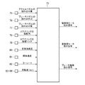
上述した駆動用モータ1a、駆動用モータ1b、差動用モータ5a、差動機構4bにおけるトルクの分配率を制御する差動用モータ5b、第1ブレーキ機構18a、第2ブレーキ機構59、第3ブレーキ機構18bを、一括して制御するための第1電子制御装置(以下、第1ECUと記す)73が設けられている。この第1ECU73は、従来知られている車両に搭載された電子制御装置と同様にマイクロコンピュータを主体として構成されており、この発明の実施例における「コントローラ」に相当する。その第1ECU73の構成を説明するためのブロック図を図3に示している。
The driving
この第1ECU73には、車両Veの姿勢に関連するデータや、運転者による操作部の操作状態などの信号が入力され、その入力される信号、および予め記憶されている演算式またはマップなどに基づいて、第1インバータ72や、蓄電装置71と各モータ1b,5bまたは第3ブレーキ機構18bとの間に配置され、直流電流と交流電流とを切替えるとともに、各モータ1b,5bまたは第3ブレーキ機構18bに供給される電流値やその周波数を制御することができる第2インバータ74に制御信号を出力するように構成されている。なお、第1ECU73から第1インバータ72や第2インバータ74に出力する制御信号を求める際には、従来知られたアンチロックシステム(ABS)、トラクションコントロール(TRC)、エレクトロニックスラビリティコントロール(ESC)、ダイナミックヨーレートコントロール(DYC)などを考慮して求めている。
The
上記第1ECU73に入力される操作状態の信号の一例としては、アクセルペダルの踏み込み量を検出するアクセルペダルセンサ75、ブレーキペダルの踏み込み力を検出する第1ブレーキペダルセンサ76、ブレーキペダルの踏み込み量を検出する第2ブレーキペダルセンサ77、ステアリングの操舵角を検出する操舵角センサ78、ステアリングの操舵トルクを検出するトルクセンサ79からの信号であり、車両Veの姿勢に関連するデータの信号の一例としては、車両Veの前後加速度を検出する第1Gセンサ80、車両Veの横加速度を検出する第2Gセンサ81、車両Veのヨーレートを検出するヨーレートセンサ82、各車輪2L,2R,3L,3Rの周速を検出する車輪速センサ83,84,85,86からの信号である。
As an example of the operation state signal input to the
なお、第1ECU73を作動させるためや、第1インバータ72に搭載されている図示しないトランジスタを制御するための電力を供給するために、第1補機バッテリ87が設けられている。この第1補機バッテリ87は、蓄電装置71よりも低電圧である。
Note that a first
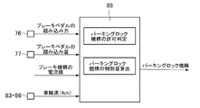
上述したようにパーキング用モータ21は、第1ブレーキ機構18aのバックアップとしても機能するため、上記第1ECU73と第1補機バッテリ87との電気系統にフェールが生じた場合、または蓄電装置71と第1インバータ72との電気系統にフェールが生じた場合などにも、第1パーキング用モータ機構21を制御することができるように、第1ECU73とは別に他の電子制御装置(以下、第2ECUと記す)88が設けられている。この第2ECU88も第1ECU73と同様にマイクロコンピュータを主体として構成されている。この第2ECU88の構成を説明するためのブロック図を図4に示している。この第2ECU88には、車両Veの姿勢に関連するデータや、運転者による操作部の操作状態などの信号が入力され、その入力される信号、および予め記憶されている演算式またはマップなどに基づいて第1パーキング用モータ機構21を作動させることを許可するか否かを判断するとともに、第1パーキング用モータ機構21の制御量を演算などにより定め、その定められた制御量に基づいて、第1パーキング用モータ機構21に制御信号を出力するように構成されている。
As described above, since the
上記第2ECU88に入力される操作状態の信号の一例としては、第1ブレーキペダルセンサ76、第2ブレーキペダルセンサ77、各ブレーキ機構18a,18bに通電されている電流値を検出する図示しないセンサからの信号であり、車両Veの姿勢に関連するデータの信号の一例としては、車輪速センサ83,84,85,86からの信号である。また、第1パーキング用モータ機構21を作動させることの許可は、所定の時間以上停車していること、アクチュエータ22を作動させるためのスイッチが運転者などによりオンされていること、停車中でかつイグニッションがオフされていること、少なくともいずれか一方のブレーキ機構18a(18b)が作動することができないことなどのいずれか一つが成立していることで判定することができる。さらに、ブレーキペダルの踏み込み力や踏み込み量と、各車輪2L,2R,3L,3Rの車輪速とから第1パーキング用モータ機構21による制動トルクを定め、その制動トルクを得られるように、アクチュエータ22および第2パーキング用モータを制御するための図示しないアクチュエータへ電流を出力するように構成されている。そして、第2ECU88を作動させるためや、第1パーキング用モータ機構21を制御するための電力を供給するために、第2補機バッテリ89が設けられている。なお、第1ECU73からの信号を第2ECU88が受けることができ、第1ECU73がフェールした場合などには、第2ECU88が作動することを許可するように構成することができる。
As an example of the operation state signal input to the
つぎに、各駆動用のモータ1a,1b、各差動用モータ5a,5b、各ブレーキ機構18a,18bに通電する電流値を定めるための制御例について説明する。図5ないし図9は、その制御例を説明するためのフローチャートであり、第1ECU73で実行される。なお、図5ないし図9は、一連のフローチャートで実行することができるものの、ここでは、便宜上、図5ないし図9に分けて説明する。図5に示す例は、運転者により要求されているトルクを算出するための制御フローであり、そのトルクは、車両Veを加速するトルク、および車両Veを減速するトルクである駆動トルクとして算出される。
Next, a control example for determining a current value for energizing each
図5に示す例では、まず、入力1次処理として、各センサ75,76,77,78,79,80,81,82,83,84,85,86から入力された信号を読み込む(ステップS1)。ついで、車輪速Vwと前後加速度Gから、以下に示す式に基づいて車速Vbを推定する(ステップS2)。このステップS2における車輪速Vwは、四輪2L,2R,3L,3Rの平均速度であってもよく、いずれかの車輪速3L(3R,4L,4R)であってもよい。
Vb=Vw×F(G)
In the example shown in FIG. 5, first, as input primary processing, signals input from the
V b = V w × F (G)
つぎに、運転者により減速することが要求されているか否かを判断する。具体的には、ブレーキペダルの踏み込み量STKbが、予め定められた閾値Ksbよりも大きいか否かが判断される(ステップS3)。このステップS3の判断は、運転者が減速することを意図してブレーキペダルを踏んでいるか否かを判断するためのものであり、前記閾値Ksbは予め実験などにより定めておくことができる。また、ブレーキペダルの踏み込み量STKbは、第1ブレーキペダルセンサ76により検出することができる。
Next, it is determined whether or not the driver is requested to decelerate. Specifically, the depression amount STK b of the brake pedal, whether large or not than the threshold value K sb predetermined (step S3). The determination in step S3 is for determining whether or not the driver is stepping on the brake pedal with the intention of decelerating, and the threshold value K sb can be determined in advance through experiments or the like. Further, the depression amount STK b of the brake pedal can be detected by the first
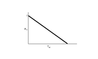
ブレーキペダルの踏み込み量STKbが、閾値Ksbよりも大きいことによりステップS3で肯定的に判断された場合には、運転者が要求する制動トルクTbkを算出する(ステップS4)。このステップS4における制動トルクTbkは、まず、ブレーキペダルの踏み込み量STKbに基づいた制動トルクTsbを、第1ECU73に予め記憶されている図10に示すマップから求める。このマップは、予め実験などによりブレーキペダルの踏み込み量STKbと制動トルクTsbとの関係に基づいて定められており、ブレーキペダルの踏み込み量STKbが大きくなるに連れて、制動トルクTsbが二次曲線的に増大するように定められている。 Depression amount STK b of the brake pedal is, if an affirmative determination is made in step S3 by greater than the threshold value K sb calculates the braking torque T bk requested by the driver (step S4). As the braking torque T bk in step S4, first, the braking torque T sb based on the depression amount STK b of the brake pedal is obtained from the map shown in FIG. This map is determined in advance based on the relationship between the brake pedal depression amount STK b and the braking torque T sb through experiments or the like. As the brake pedal depression amount STK b increases, the braking torque T sb increases. It is determined to increase in a quadratic curve.
ついで、ブレーキ踏み込み力Fbに基づいた制動トルクTbpを、第1ECU73に予め記憶されている図11に示すマップから求める。このマップは、予め実験などによりブレーキペダルの踏み込み力Fbと制動トルクTbpとの関係に基づいて定められており、ブレーキペダルの踏み込み力Fbが所定値以下の場合には、制動トルクTbpが「0」に定められ、ブレーキペダルの踏み込み力Fbが所定値よりも大きい時には、ブレーキペダルの踏み込み力Fbが大きくなるに連れて制動トルクTbpが比例的に大きくなるように定められている。
Next, a braking torque T bp based on the brake depression force F b is obtained from a map shown in FIG. 11 stored in advance in the
そして、上記のように各マップから求められた制動トルクTsb,Tbpから、運転者が要求する制動トルクTbkを求める。具体的には、以下の式により求める。
Tbk=ab×Tsb+(1−ab)×Tbp
上記の式におけるabは、運転者が要求する制動トルクTbkを求める際における、制動トルクTsbの寄与率であって、第1ECU73に記憶されている図12に示すマップに基づいて定めることができる。なお、図12に示すマップは、制動トルクTsbが大きくなるに連れて、寄与率abが比例的に小さくなるように定められている。
Then, the braking torque T bk requested by the driver is obtained from the braking torques T sb and T bp obtained from each map as described above. Specifically, it is obtained by the following formula.
T bk = a b × T sb + (1-a b ) × T bp
A b in the above equation is a contribution ratio of the braking torque T sb when determining the braking torque T bk requested by the driver, and is determined based on the map shown in FIG. 12 stored in the
ついで、制動側判定時処理として、運転者が要求する駆動トルクTacを「0」にし、かつ制動側判定フラグFbkをセット(オン)する(ステップS5)。 Next, as the braking-side determination time process, the driving torque Tac requested by the driver is set to “0”, and the braking-side determination flag F bk is set (ON) (step S5).
一方、ブレーキペダルの踏み込み量STKbが、閾値Ksb以下であって、ステップS3で否定的に判断された場合には、運転者が要求する駆動トルクTacを算出する(ステップS6)。このステップS6は、以下の式により求めることができる。
Tac=Ka×STKa
なお、上記Kaは、アクセルペダルの操作量STKaを、駆動トルクTacに換算するために予め定められた係数である。
On the other hand, when the depression amount STK b of the brake pedal is equal to or less than the threshold value K sb and the determination is negative in step S3, the driving torque T ac requested by the driver is calculated (step S6). This step S6 can be obtained by the following equation.
T ac = K a × STK a
The K a is a coefficient determined in advance for converting the accelerator pedal operation amount STK a into the drive torque T ac .
そして、駆動側判定時処理として、運転者が要求する制動トルクTbkを「0」にし、かつ制動側判定フラグFbkをリセット(オフ)する(ステップS7)。 Then, as the driving side determination time process, the braking torque T bk requested by the driver is set to “0”, and the braking side determination flag F bk is reset (turned off) (step S7).
上述したように運転者が要求する制動トルクTbkと駆動トルクTacとを算出した後、車両Veに要求されるトルクTdrを、以下の式に基づいて算出する(ステップS8)。
Tdr=Tac−Tbk
As described above, after calculating the braking torque T bk and the driving torque T ac required by the driver, the torque T dr required for the vehicle Ve is calculated based on the following equation (step S8).
T dr = T ac -T bk
このステップS8は、車両Veを前後方向に駆動させるトルクを一律に演算するために、前進走行している車両Veが加速するように出力するトルクを「正」の値とし、減速するように出力するトルクを「負」の値とするためである。すなわち、ステップS4で求められる制動トルクTbkは、正の値となるため、この制動トルクTbkを負の値の要求トルクと置き換えるために設けられている。 In step S8, in order to uniformly calculate the torque that drives the vehicle Ve in the front-rear direction, the torque that is output so that the vehicle Ve traveling forward accelerates is set to a positive value and output so as to decelerate. This is because the torque to be applied is set to a “negative” value. That is, the braking torque T bk obtained in step S4, since a positive value, is provided to replace the braking torque T bk and the required torque of a negative value.
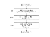
上記のように運転者による要求トルクTdrを算出した後に、車両Veの右側の駆動輪(前輪3Rと後輪4Rとから出力するトルクの和)に伝達するべきトルクTr diと、車両Veの左側の駆動輪(前輪3Lと後輪4Lとから出力するトルクの和)に伝達するべきトルクTl diとを定めるために図6に示すフローチャートを実行する。これは、旋回走行時などにおける走行安定性を向上させるためである。すなわち、図6に示すフローチャートが、従来知られているエレクトロニックスタビリティコントロール(ESC)、ダイナミックヨーレートコントロール(DYC)を考慮した制御であり、車両Veの姿勢に関連するデータ、より具体的には、ヨーレートセンサ82により検出された実際のヨーレートに基づいて車両Veの右側の駆動輪に伝達するべきトルクTr diと、車両Veの左側の駆動輪に伝達するべきトルクTl diを算出する。
After calculating the driver's required torque T dr as described above, the torque T r di to be transmitted to the right drive wheel of the vehicle Ve (the sum of the torques output from the
図6に示す例では、まず、ステアリングの操舵角δから目標ヨーレートγtgtを算出する(ステップS9)。この目標ヨーレートγtgtは、従来知られているように以下の式で算出することができる。
γtgt=((1/1+A×Vb 2)×(Vb/l))×(δ/n)
なお、上式におけるAは目標スタビリティファクタを示し、lはホイールベースを示し、nはステアリングのギヤ比を示している。
In the example shown in FIG. 6, first, the target yaw rate γ tgt is calculated from the steering angle δ of the steering (step S9). This target yaw rate γ tgt can be calculated by the following equation as conventionally known.
γ tgt = (( 1/1 + A × V b 2 ) × (V b / l)) × (δ / n)
In the above equation, A represents the target stability factor, l represents the wheel base, and n represents the gear ratio of the steering.
ついで、ステップS9で算出された目標ヨーレートγtgtと、ヨーレートセンサ82により検出された実際のヨーレートγrealとの偏差Δγを求め(ステップS10)、目標ヨーレートγtgtに追従するために車両Veの右側の駆動輪から出力するべきトルクTr diと、車両の左側の駆動輪から出力するべきトルクTl diとを、以下の式に基づいて算出する(ステップS11)。
Tr di=−Kγ×Δγ
Tl di=Kγ×Δγ
なお、Kγは、左右のトルクの分配係数であって、第1ECU73に予め記憶されている。以下の説明では、ステップS11で算出されるトルクを、「分配トルク」と記す。
Next, a deviation Δγ between the target yaw rate γ tgt calculated in step S9 and the actual yaw rate γ real detected by the
T r di = −K γ × Δγ
T l di = K γ × Δγ
K γ is a left-right torque distribution coefficient, and is stored in the
このステップS11は、走行安定性を向上させるために一方側の駆動輪3R,4R(3L,4L)に伝達するトルクを増大させ、他方側の駆動輪3L,4L(3R,4R)に伝達するトルクを減少させる量を求めるためであり、その増大量と減少量とが同一となるように定めている。これは、上述したように差動機構4a,4bは、一方の駆動輪3R(3L)に伝達するトルクの分配率を増大させるように差動用モータ5a,5bを制御した場合には、他方の駆動輪3L(3R)に伝達するトルクの分配率が同じ数値、減少するように構成されているためである。
This step S11 increases the torque transmitted to the
つぎに、運転者の要求トルクTdrと、各分配トルクTr di,Tl diとから、各駆動用モータ1a,1bおよび各差動用モータ5a,5bならびにブレーキ機構18a,18bへ通電する電流値I*m,I*s,I*bを定める。具体的には、図7に示す制御例に基づいて実際に各車輪2L,2R,3L,3Rに伝達するべき駆動トルクTi wlaや制動トルクTi wlbを算出し、その後に、図8に示す制御例に基づいて、各駆動用モータ1a,1bおよび各差動用モータ5a,5bならびにブレーキ機構18a,18bへ通電する電流値I*m,I*s,I*bを定める。
Next, a required torque T dr of the driver to energize each distribution torque T r di, and a T l di, each of the
図7に示す制御例では、まず、運転者が駆動トルクを要求しているかを判断する(ステップS12)。具体的には、図5におけるステップS5やステップS7で定められたフラグFbkが、オフになっているか否かを判断する。 In the control example shown in FIG. 7, first, it is determined whether the driver is requesting drive torque (step S12). Specifically, it is determined whether or not the flag F bk set in step S5 or step S7 in FIG. 5 is turned off.
運転者が駆動トルクを要求していることによりステップS12で肯定的に判断された場合には、ステップS8で算出された要求トルクTdrと、ステップS11で算出された各分配トルクTr di,Tl diとから、各車輪2L,2R,3L,3Rに伝達するべきトルクTfr w,Tfl w,Trr w,Trl wを、以下に示す式に基づいて算出する(ステップS13)。
Tfr w=1/6×Tdr+1/3Tr di
Tfl w=1/6×Tdr+1/3Tl di
Trr w=1/3×Tdr+2/3Tr di
Trl w=1/3×Tdr+2/3Tl di
なお、上式における「Tfr w」は、右前輪2Rに伝達するべきトルクを示し、「Tfl w」は、左前輪2Lに伝達するべきトルクを示し、「Trr w」は、右後輪3Rに伝達するべきトルクを示し、「Trl w」は、左後輪3Lに伝達するべきトルクを示している。また、駆動トルクを出力する場合には、後輪3L,3R側の接地荷重が増大するため、前輪2L,2Rの要求トルクTdrおよび各分配トルクTr di,Tl diと、後輪3L,3Rの要求トルクTdrおよび分配トルクTr di,Tl diとの配分を1対2としている。この配分率は、車両Veの構成などに応じて適宜定めてもよい。
If the determination in step S12 is affirmative because the driver is requesting drive torque, the requested torque Tdr calculated in step S8 and the distribution torques T r di , calculated in step S11, are determined. Based on T l di , torques T fr w , T fl w , T rr w , T rl w to be transmitted to the
T fr w = 1/6 × T dr +1/3 T r di
T fl w = 1/6 × T dr +1/3 T l di
T rr w = 1/3 × T dr +2/3 T r di
T rl w = 1/3 × T dr + 2 / 3T l di
In the above equation, “T fr w ” indicates the torque to be transmitted to the
ついで、車速Vbと、各車輪2L,2R,3L,3Rの車輪速Vi wとから駆動時における各車輪2L,2R,3L,3Rのスリップ率Si aを、各車輪2L,2R,3L,3Rのそれぞれについて以下の式に基づいて算出する(ステップS14)。すなわち、各車輪2L,2R,3L,3Rのスリップ状態を検出する。
Si a=(Vi w/Vb)−1
なお、ここでは、便宜上、一つの式を示しているものの、実際には、各車輪2L,2R,3L,3R毎に上式でスリップ率を演算する。以下の説明では、便宜上、各車輪2L,2R,3L,3R毎に演算する式を一つのみ示し、その演算に用いられるパラメータに、「i」を付して示す。
Then, the vehicle speed V b and each of the
S i a = (V i w / V b ) −1
In addition, although one formula is shown here for convenience, actually, the slip ratio is calculated by the above formula for each
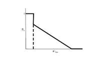
そして、ステップS14で算出されたスリップ率Si aから、それぞれの車輪2L,2R,3L,3Rに伝達するトルクの制限率αi limaを算出する(ステップS15)。これは、従来知られているトラクションコントロール(TRC)を考慮したものであって、スリップ率Si aが大きい車輪に過度にトルクが伝達されることを抑制するためである。このステップS15は、図13に示すマップに基づいて算出することができる。このマップは、予め実験などに基づいて定められたものであって第1ECU73に記憶されており、スリップ率Si aが所定値よりも大きい場合に、制限率αi limaを一定値に定め、スリップ率Si aが所定値以下の場合には、スリップ率Si aが小さくなるに連れて制限率αi limaが大きくなるように定められている。
Then, the slip ratio S i a calculated in step S14, calculates the
ついで、各車輪毎2L,2R,3L,3RにステップS13で算出されたトルクTi wと、ステップS15で算出された制限率αi limaとから実際に各車輪2L,2R,3L,3Rに伝達するための指示トルクTi wlaを、以下の式に基づいて算出する(ステップS16)。
Ti wla=Ti w×αi lima
Next, each
T i wla = T i w × α i lima
一方、制動側判定フラグFbkがオンになっており、ステップS12で否定的に判断された場合には、ステップS8で算出された要求トルクTdrと、ステップS11で算出された各分配トルクTr di,Tl diとから、各車輪2L,2R,3L,3Rに伝達するべきトルクTfr w,Tfl w,Trr w,Trl wを、以下に示す式に基づいて算出する(ステップS17)。
Tfr w=1/3×Tdr+2/3Tr di
Tfl w=1/3×Tdr+2/3Tl di
Trr w=1/6×Tdr+1/3Tr di
Trl w=1/6×Tdr+1/3Tl di
なお、ステップS17では、制動トルクを出力することとなるため、その場合には、上述したステップS13とは異なり、前輪2L,2R側の接地荷重が増大する。そのため、上式では、前輪2L,2Rの要求トルクTdrおよび各分配トルクTr di,Tl diと、後輪3L,3Rの要求トルクTdrおよび各分配トルクTr di,Tl diとの配分を2対1としている。この配分率は、車両Veの構成などに応じて適宜定めてもよい。
On the other hand, if the braking side determination flag Fbk is on and a negative determination is made in step S12, the required torque Tdr calculated in step S8 and each distribution torque T calculated in step S11. Torques T fr w , T fl w , T rr w , T rl w to be transmitted to the
T fr w = 1/3 × T dr +2/3 T r di
T fl w = 1/3 × T dr +2/3 T l di
T rr w = 1/6 × T dr +1/3 T r di
T rl w = 1/6 × T dr +1/3 T l di
In step S17, braking torque is output. In this case, unlike the above-described step S13, the ground load on the
ついで、車速Vbと、各車輪2L,2R,3L,3Rの車輪速Vi wとから制動時における各車輪2L,2R,3L,3Rのスリップ率Si bを、各車輪2L,2R,3L,3Rのそれぞれについて以下の式に基づいて算出する(ステップS18)。
Si b=1−(Vi w/Vb)
Then, the vehicle speed V b and each of the
S i b = 1− (V i w / V b )
そして、ステップS18で算出されたスリップ率Si bから、それぞれの車輪2L,2R,3L,3Rに伝達するトルクの制限率αi limbを算出する(ステップS19)。これは、従来知られているアンチロックシステム(ABS)を考慮したものであって、スリップ率Si bが大きい車輪に過度に制動トルクが伝達されることを抑制するためである。このステップS19は、図14に示すマップに基づいて算出することができる。このマップは、予め実験などに基づいて定められたものであって第1ECU73に記憶されており、スリップ率Si bが所定値よりも大きい場合に、制限率αi limbを所定値で一定に定め、スリップ率Si bが所定値以下の場合には、スリップ率Si bが小さくなるに連れて制限率αi limbが大きくなるように定められている。
Then, from the slip rate S i b calculated in step S18, a limit rate α i limb of torque transmitted to each
ついで、各車輪2L,2R,3L,3R毎にステップS17で算出されたトルクTi wと、ステップS19で算出された制限率αi limbとから実際に各車輪2L,2R,3L,3Rに伝達するための指示トルクTi wlbを、以下の式に基づいて算出する(ステップS20)。
Ti wlb=Ti w×αi limb
Next, each
T i wlb = T i w × α i limb
上述したように駆動時には、ステップS13で各車輪2L,2R,3L,3Rに伝達するべきトルクTi wを算出し、そのトルクTi wに制限率αi limaを積算して指示トルクTi wlaを算出している。言い換えると、各車輪各車輪2L,2R,3L,3Rに伝達するべきトルクTi wを、スリップ率Si aに基づいて補正する。同様に制動時には、ステップS17で各車輪2L,2R,3L,3Rに伝達するべきトルクTi wを算出し、そのトルクTi wに制限率αi limbを積算して指示トルクTi wlbを算出している。結局、各車輪各車輪2L,2R,3L,3Rに伝達するべきトルクTi wを、スリップ率Si bに基づいて補正する。
As described above, at the time of driving, the torque T i w to be transmitted to each of the
つぎに、ステップS16およびステップS20で算出された指示トルクTi wla,Ti wlbに基づいて、各駆動用モータ1a,1bおよび各差動用モータ5a,5bならびにブレーキ機構18a,18bへ通電する電流値I*m,I*s,I*bを定める。まず、駆動時には、ステップS16で算出された指示トルクTi wlaから各駆動用モータ1a,1bへ通電する電流値I*m a、および各差動用モータ5a,5bへ通電するI*s aを以下の式に基づいて算出する(ステップS21)。
I*m a=KIma×(T*r wla+T*l wla)
I*s a=KIs×(T*r wla−T*l wla)/2
上式におけるKImaは、駆動用モータ1aや駆動用モータ1bに要求されるトルクを電流値に変換するための定数(変換定数)であって、予め第1ECU73に記憶されている。ここで、「*」は、前方および後方のそれぞれについての値を示している。すなわち、上式におけるI*m aは、右前輪2Rと左前輪2Lとについて算出された指示トルクを加算し、その指示トルクに変換定数KImaを積算して、駆動用モータ1aへ通電する電流値を求めるとともに、右後輪3Rと左後輪3Lとについて算出された指示トルクを加算し、その指示トルクに変換定数KImaを積算して、駆動用モータ1bへ通電する電流値を求める。また、上式におけるI*s aは、右前輪2Rについて算出された指示トルクと左前輪2Lについて算出された指示トルクとの差を半分とし、その値に変換定数KIsを積算して、駆動用モータ1aへ通電する電流値を求めるとともに、右後輪3Rについて算出された指示トルクと左後輪3Lについて算出された指示トルクとの差を半分とし、その値に変換定数KIsを積算して、駆動用モータ1bへ通電する電流値を求める。
Next, the
I * m a = K Ima × (T * r wla + T * l wla )
I * s a = K Is × (T * r wla −T * l wla ) / 2
K Ima in the above equation is a constant (conversion constant) for converting torque required for the
そして、ステップS21により算出された電流値I*m a,I*s aを各駆動用モータ1a,1bおよび各差動用モータ5a,5bに出力する(ステップS22)。
Then, the current values I * m a and I * s a calculated in step S21 are output to the
一方、運転者が減速を意図している場合であって、ステップS12で否定的に判断され、ステップS20で各車輪2L,2R,3L,3Rに伝達するための指示トルク(制動トルク)Ti wlbを算出した場合には、ついで、全ての車輪2L,2R,3L,3Rに伝達するための指示トルクを加算して、全制動トルクTtrcを算出する(ステップS23)。
Ttrc=(T*r wlb+T*l wlb/γtrc)
Tdiff=(T*r wlbーT*l wlb/γdiff)
上式における「Ttrc」は、駆動用モータ1a,1bとブレーキ機構18,18bとが出力すべき目標トルクを示し、「Tdiff」は、差動用モータ5a,5bの目標トルクを示している、また「γtrc」は制動部および駆動部の減速比を示し、「γdiff」は差動部の減速比を示している。さらに、「*」は、前輪および後輪のそれぞれについての値を示している。
On the other hand, if the driver intends to decelerate, the instruction torque (braking torque) T i is determined to be negative in step S12 and transmitted to the
T trc = (T * r wlb + T * l wlb / γ trc )
T diff = (T * r wlb −T * l wlb / γ diff )
“T trc ” in the above equation indicates a target torque to be output by the driving
そして、ステップS23で算出された全制動トルクTtrcが、駆動用モータ1aおよび駆動用モータ1bで回生可能か否かが判断される(ステップS24)。すなわち、各モータ1a,1bが回生制御することにより生じる制動トルクにより全制動トルクTtrcを受け持つことができるか否かが判断される。具体的には、以下の式が成立するか否かが判断される。
Ttrc>Tkai
なお、上式におけるTkaiは、各モータ1a,1bの特性などに基づいて予め定められている回生トルクの最大値である。
Then, it is determined whether or not the total braking torque T trc calculated in step S23 can be regenerated by the driving
T trc > T kai
Note that T kai in the above equation is the maximum value of the regenerative torque that is determined in advance based on the characteristics of the
各モータ1a,1bで全制動トルクTtrcを回生することができ、ステップS24で肯定的に判断された場合には、ステップS20で算出された指示トルクTi wlbから各駆動用モータ1a,1bおよび各差動用モータ5a,5bへ通電する電流値I*m b,I*s bを以下の式に基づいて算出する(ステップS25)。
I*m b=KIb×(T*r wlb+T*l wlb)
I*s b=KIb×(T*r wlb−T*l wlb)/2
上式におけるKIbは、駆動用モータ1aや駆動用モータ1b、差動用モータ5aや差動用モータ5bに要求されるトルクを電流値に変換するための定数(変換定数)であって、予め第1ECU73に記憶されている。なお、ステップS25における式は、ステップS21と同様に演算することができる。
The total braking torque T trc can be regenerated by the
I * m b = K Ib × (T * r wlb + T * l wlb )
I * s b = K Ib × (T * r wlb -T * l wlb) / 2
KIb in the above equation is a constant (conversion constant) for converting torque required for the
一方、全制動トルクTtrcを各駆動用モータ1a,1bで回生することができず、ステップS24で否定的に判断された場合には、まず、回生可能な範囲で各駆動用モータ1a,1bを回生制御し、余剰の制動トルクをブレーキ機構18a,18bで生じさせるように電流制御を行う(ステップS26)。なお、その際における各差動用モータ5a,5bへ通電する電流値ICは、ステップ25と同様に算出する。具体的には、各駆動用モータ1a,1bへ通電する電流値IM、各差動用モータ5a,5bへ通電する電流値IC、各ブレーキ機構18a,18bへ通電する電流値IBを算出する。
IM(Tkai),IC(Tdiff),IB(TREF B)
なお、上式における「TREF B」は、ブレーキ機構18a,18b(制動装置)の指示トルクを示している。上式に示すように各ブレーキ機構18a,18bへ通電する電流値IBも、ステップS21における各駆動用モータ1a,1bに通電する電流値I*m aと同様に右前輪2Rについて算出された指示トルクと左前輪2Lについて算出された指示トルクとの差、または右後輪3Rについて算出された指示トルクと左後輪3Lについて算出された指示トルクとの差に基づいて算出する。
On the other hand, if the total braking torque T trc cannot be regenerated by the
I M (T kai ), I C (T diff ), I B (T REF B )
Note that “T REF B ” in the above equation indicates the command torque of the
このように、各駆動用モータ1a,1bおよび各差動用モータ5a,5bならびに各ブレーキ機構18a,18bによって制動トルクを受け持つように、通電する電流値を制御することによりエネルギーの回生効率を向上させることができるとともに、各ブレーキ機構18a,18bが受け持つ制動トルクを小さくすることができる。しかしながら、摩擦材の温度の変化や摩耗等により、実際に出力される制動トルクと、上記のステップS26で算出した電流値により出力されるべき制動トルク(指示トルク)とが乖離して、意図した制動トルクが出力されない場合がある。そこで、この発明における制御例では、制動時に駆動用モータ1a,1b側のブレーキ機構18a,18bにおけるアクチュエータ22の制御量を制御することにより、制動トルクTREF Bを適切に発生させるように構成されている。以下に、その制御例について説明する。
In this way, the energy regeneration efficiency is improved by controlling the value of the energized current so that the driving
図9は、その制御例を示すフローチャートであって、特にブレーキ機構18a,18bに出力する電流値IBを制御する。先ず、上述した図8のステップS26についで、各ブレーキ機構18a,18bに通電する電流値IBのフィードフォワード制御を実行する(ステップS100)。このステップS100は、ステップS26で算出したブレーキ機構18a,18bの指示トルクTREF Bに基づいて実行される。このフィードフォワード制御を簡略化して表すと以下のように示すことができる。
IFF B=IB(TREF B)
Figure 9 is a flowchart showing the control example, it controls the current value I B to output
I FF B = I B (T REF B )
ついで、推定制動トルクTEST Bを演算する(ステップS101)。この推定制動トルクTEST Bは設計値等の所定の値を用いて算出される。例えば、車両Veの重量Mvと加速度センサから得られる前後加速度axとから算出することができる。これを簡略化して表すと以下のように示すことができる。
TEST B=Mv *(-ax)/γtrc
Next, the estimated braking torque T EST B is calculated (step S101). The estimated braking torque T EST B is calculated using a predetermined value such as a design value. For example, it can be calculated from the longitudinal acceleration a x obtained from the weight M v and the acceleration sensor of the vehicle Ve. This can be shown in a simplified manner as follows.
T EST B = M v * (-a x ) / γ trc
ついで、上記のステップS101で算出された推定制動トルクTEST Bと、指示トルクTREF Bとの偏差ΔTBを演算する(ステップS102)。これは上述したように、ステップS26で算出された電流値IBによって、制動トルクが実際に車両Veの挙動として出力されているか否かを判断するためのステップである。したがって、この偏差ΔTBを把握することで、指示トルクTREF Bと推定制動トルクTEST Bとの乖離が把握できる。これを簡略化して表すと以下のように示すことができる。
ΔTB=TREF BーTEST B
Next, a deviation ΔT B between the estimated braking torque T EST B calculated in step S101 and the command torque T REF B is calculated (step S102). This is because, as described above, by the current value I B calculated in the step S26, a step for determining whether the braking torque is actually outputted as behavior of the vehicle Ve. Therefore, by grasping this deviation ΔT B , it is possible to grasp the difference between the command torque T REF B and the estimated braking torque T EST B. This can be shown in a simplified manner as follows.
ΔT B = T REF B -T EST B
ついで、その偏差ΔTBが予め定められた閾値ΔT1未満か否かが判断される(ステップS103)。これは、上記の推定制動トルクTEST Bと指示トルクTREF Bとの偏差ΔTBが、許容できる範囲の偏差ΔTBか否かの判断である。つまり、その偏差ΔTBが許容できる範囲である場合には、推定制動トルクTEST Bと指示トルクTREF Bとの乖離が小さいと判断できる。一方、その偏差ΔTBが許容できる範囲、すなわち閾値ΔT1未満でないと判断された場合には、推定制動トルクTEST Bと指示トルクTREF Bとの乖離が大きいと判断できる。これを簡略化して表すと以下のように示すことができる。
|ΔTB|<ΔT1
このステップS103で否定的に判断された場合、すなわち偏差ΔTBが閾値ΔT1未満でないと判断された場合には、推定制動トルクTEST Bと指示トルクTREF Bとの乖離が大きいと判断される。したがって、正確な指示トルクTREF Bを出力するように補正する必要がある。そこで、先ず、所定の時間、予め定められた制動力TADD Bを加算する(ステップS104)。具体的には、ドライブシャフトより入力側のいずれかの回転部材(図2に示す例では、例えば、出力軸11や第1回転体13)に制動トルクTADD Bを加算する。なお、この制動トルクTADD Bは、振動を加算するものであって、アクチュエータ22の制御量を所定の周波数で振動させる。簡略化して表すと以下のように示すことができる。
IB=IFF B+IB(TADD B)sin(2πfreft)
Next, it is determined whether or not the deviation ΔT B is less than a predetermined threshold value ΔT 1 (step S103). This deviation [Delta] T B between the command torque T REF B above estimated braking torque T EST B is a determination of whether an acceptable range of deviation [Delta] T B. That is, when the deviation ΔT B is within an allowable range, it can be determined that the difference between the estimated braking torque T EST B and the command torque T REF B is small. On the other hand, if it is determined that the deviation ΔT B is not in an allowable range, that is, less than the threshold value ΔT 1, it can be determined that the difference between the estimated braking torque T EST B and the command torque T REF B is large. This can be shown in a simplified manner as follows.
| ΔT B | <ΔT 1
If a negative determination is made in step S103, that is, if it is determined that the deviation ΔT B is not less than the threshold value ΔT 1 , it is determined that the difference between the estimated braking torque T EST B and the command torque T REF B is large. The Therefore, it is necessary to make corrections so as to output an accurate instruction torque T REF B. Therefore, first, a predetermined braking force T ADD B is added for a predetermined time (step S104). Specifically, the braking torque T ADD B is added to any rotating member on the input side from the drive shaft (for example, the
I B = I FF B + I B (T ADD B ) sin (2πf ref t)
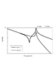
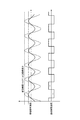
なお、ドライブシャフトより入力側の回転部材11に制動力TADD Bを加算するのは、ドライブシャフトより入力側でトルクを加算した場合は、路面環境等の外乱がなく、車両運動に影響を及ぼさないためである。また特に、図15に示すように、ドライブシャフトより入力側(インボード側)の回転部材11と車輪側(アウトボード側)との双方の周波数が一時的に高くなる共振周波数より高い周波数で振動させることにより、実線(インボード側)と破線(アウトボード側)とで示したゲインGは、アウトボード側で大きく低下する。すなわち、この範囲で振動させた場合には、インボード側の回転速度の変動は大きく、アウトボード側の回転速度の変動を小さくなる。要は、この範囲でアクチュエータ22の制御量を振動させることにより、各車輪2L,2R,3L,3Rに出力されるトルクはドライブシャフトにより減衰されるため車両運動に影響が出ない。
Note that the braking force T ADD B is added to the rotating
ついで、ステップS104でアクチュエータ22の制御量を振動させた状態における回転部材11の回転数ωHPF DIを検出する(ステップS105)。このステップS104の回転数ωHPF DIは、図示しないレゾルバなどの回転数センサによって回転部材11の回転数ωHPF DIを検出する。ついで、ステップS105で検出された回転数ωHPF DIが振動することによる振幅|ωHPF DI|を求める(ステップS105)。ステップS105の振幅|ωHPF DI|は、例えば、図15に示すようなマップ等から求めることができる。なお、この回転数ωHPF DIが振動することによる振幅|ωHPF DI|は、上述したように、所定の高い周波数でアクチュエータ22の制御量を振動させるため、所定の周波数より低い帯域の信号をカットしたハイパスフィルタ処理済みの信号を採用する。
Next, the rotational speed ω HPF DI of the rotating
ついで、ステップS105で求めた回転数ωHPF DIの振幅|ωHPF DI|に相当する回転部材11のトルクの振幅|TRESULT B|を求める(ステップS107)。これは例えば、上述した図15のゲインGDI(fref)とステップS106で求めた回転数の振幅|ωHPF DI|とから求めることができる。これを簡略化して表すと以下のように示すことができる。
GDI(fref)=20log(|ωHPF DI|/|TRESULT B|)
これにより実際の制動トルクの変動量、すなわち振幅|TRESULT B|を求めることができる。
Next, the torque amplitude | T RESULT B | corresponding to the amplitude | ω HPF DI | of the rotational speed ω HPF DI obtained in step S105 is obtained (step S107). This can be obtained from, for example, the above-described gain G DI (f ref ) in FIG. 15 and the rotation speed amplitude | ω HPF DI | obtained in step S106. This can be shown in a simplified manner as follows.
G DI (f ref ) = 20 log (| ω HPF DI | / | T RESULT B |)
Thereby, the actual fluctuation amount of the braking torque, that is, the amplitude | T RESULT B | can be obtained.
そして、このステップS107で算出した振幅|TRESULT B|と、所定の周波数で振動させた制御量から推定されるブレーキ機構18a,18bのトルクの振幅|TADD B|とに基づいて、アクチュエータ22の制御量と回転部材11のトルクとの相関関係を求める(ステップS108)。つまり、ブレーキ機構18a,18bのトルクの振幅|TADD B|とステップS107で算出した振幅|TRESULT B|との比を求めて、それを補正係数αとして算出する。これを簡略化して表すと以下のように示すことができる。
α=TADD B/TRESULT B
なお、この補正係数αは、上記のようにトルクの振幅から算出することに代えて、ステップS105で検出した回転数ωHPF DIとステップS104で加算した制動力TADD Bの回転数とから求めてもよい。つまり、トルクに代えて、回転数の比で求めてもよい。
Based on the amplitude | T RESULT B | calculated in step S107 and the amplitude | T ADD B | of the torque of the
α = T ADD B / T RESULT B
The correction coefficient α is obtained from the rotational speed ω HPF DI detected in step S105 and the rotational speed of the braking force T ADD B added in step S104, instead of calculating from the torque amplitude as described above. May be. That is, instead of the torque, the rotation speed ratio may be obtained.
そして、上記の相関関係に基づいて、回転部材11のトルクが目標制動トルクとなるようにアクチュエータ22の制御量を制御する。つまり、上記の式で算出された補正係数αを指示トルクTREF Bに積算してアクチュエータ22の制御量を制御する。これを簡略化して表すと以下のように表すことができる。
IB=IB(TREF B)*α
Based on the above correlation, the control amount of the
I B = I B (T REF B ) * α
そして、ステップS26およびステップS108により算出された電流値IM,IC,IBを各駆動用モータ1a,1bおよび各差動用モータ5a,5bならびにブレーキ機構18a,18bに出力する(ステップS22)。
Then, the current value I M calculated by the step S26 and step S108, I C, each of the
一方、ステップS103で肯定的に判断、すなわち、推定制動トルクTEST Bと指示トルクTREF Bとの偏差ΔTBが閾値ΔT1未満と判断された場合には、フィードバック電流制御を実行する(ステップS109)。つまり、推定制動トルクTEST Bと指示トルクTREF Bとの偏差ΔTBが乖離しておらず、許容できる範囲であると判断された場合には、ステップS100で出力した電流値IFF Bと、上記の偏差ΔTBと、フィードバック係数KPとから電流値IBを算出する。これを簡略化して表すと以下のように示すことができる。
IB=IFF B+KPΔTB
そして、ステップS26およびステップS109により算出された電流値IM,IC,IBを各駆動用モータ1a,1bおよび各差動用モータ5a,5bならびにブレーキ機構18a,18bに出力する(ステップS22)。
On the other hand, affirmative determination is made in step S103, i.e., if the deviation [Delta] T B between the estimated braking torque T EST B and instruction torque T REF B is determined to be less than the threshold value [Delta] T 1 executes the feedback current control (step S109). In other words, the estimated braking torque T EST B command torque T REF deviation [Delta] T B is not deviated with B, and when it is determined that the allowable range, the current value I FF B output in step S100 The current value I B is calculated from the deviation ΔT B and the feedback coefficient K P. This can be shown in a simplified manner as follows.
I B = I FF B + K P ΔT B
Then, the current value I M calculated by the step S26 and step S109, I C, each of the
このように、図5ないし図9に示す制御例では、制動時に、各駆動用モータ1a,1bで全制動トルクTtrcを回生することができる場合には、各駆動用モータ1a,1bのみで制動トルクを受け持つように、各駆動用モータ1a,1bに通電する電流値I*m bを制御する。そのため、エネルギーの回生効率を向上させることができる。また、各駆動用モータ1a,1bで全制動トルクTtrcを回生することができない場合であっても、各駆動用モータ1a,1bにより回生することができる範囲で各駆動用モータ1a,1bが制動トルクを受け持つように、各駆動用モータ1a,1bに通電する電流値IMを制御し、余剰の制動トルクを各ブレーキ機構18a,18bで受け持つように電流値IBを制御する。
As described above, in the control examples shown in FIGS. 5 to 9, when the total braking torque T trc can be regenerated by the driving
さらに、その余剰の制動トルクを各ブレーキ機構18a,18bで受け持つように電流値IBを制御する際に、推定制動トルクTEST Bと指示トルクTREF Bとの偏差ΔTBを考慮して電流値IBを制御している。特に、上記の偏差ΔTB閾値ΔT1より大きい場合には、路面環境等の外乱がない入力側の回転部材11,(13)をアクチュエータ22により所定の周波数で振動させ、その状態での回転部材11の振幅TRESULT Bと、所定の周波数で振動させた制御量から推定されるブレーキ機構18a,18bのトルクの振幅TADD Bとの相関関係を求めている。要は、推定値TADD Bと実際値TRESULT Bとの相関関係を求めている。そして、その求められた相関関係に基づいて、回転部材11のトルクが目標制動トルクとなるようにアクチュエータ22の制御量を制御している。
Moreover, its surplus braking torque of each
また、上記の回転部材11を振動させる際に、特に、図15のマップ等に示すように、所定の高周波数領域で振動を加算するように構成されている。つまり、入力部材(インボード側)での回転速度の変動は大きく、車輪側(アウトボード側)での回転速度の変動は小さい。そのため、このような振動を加算した場合であっても、車輪側はドライブシャフト等によりその振動が減衰されるため、結果として車両運動に影響を及ぼすことなく、推定値TADD Bと実際値TRESULT Bとの相関関係を求めることができる。したがって、路面環境や、摩擦材等の摩耗、制動時の条件や経時劣化等により装置の特性が変化している場合でも、適宜補正することにより所望の制動トルクを出力することができる。また、このような簡単な構成によって実際の制動トルクを出力することができることにより、別途、他のセンサなどを搭載する必要がなく、コストの増大ならびに装置全体としての大型化を抑制することができる。さらに、必要なときに実際の制動トルクを把握することができ、その情報を基に制御もしくは制動装置に関する情報を更新することで、常に正確な制動トルクを得られるようになる。
Further, when the rotating
つぎに、この発明を応用することが可能な参考例について説明する。上述したように、図9に示した制御例は、制動時に駆動用モータ1a,1b側のブレーキ機構18a,18bにおけるアクチュエータ22の制御量を制御することにより、制動トルクを適切に出力するように構成されている。図16に示す参考例は、これに代えて差動要求がある場合など、差動制限トルクが発生している場合の例であって、各差動用モータ5a,5b側のブレーキ機構59におけるアクチュエータ67の制御量を制御することにより、制動トルクを適切に出力するように構成された例である。なお、この制御例は、上述した図9のステップS103ないしS108とほぼ同様である。したがって、以下に示す、各ステップの説明は簡略化もしくは同様の説明する。
Next, reference examples to which the present invention can be applied will be described. As described above, in the control example shown in FIG. 9, the braking torque is appropriately output by controlling the control amount of the
先ず、所定の時間、制動トルクTADD Bを加算する(ステップS200)。これは上述したステップS104と同様のステップであって、各差動用モータ5a,5b側の回転部材53,(55)に制動力TADD B(振動)を加算する。つまり、アクチュエータ67の制御量を所定の周波数で振動させる。これを簡略化して表すと、ステップS104と同様に以下のように示すことができる。
IB=IFF B+IB(TADD B)sin(2πfreft)
First, the braking torque T ADD B is added for a predetermined time (step S200). This is the same step as step S104 described above, and the braking force T ADD B (vibration) is added to the rotating members 53 (55) on the
I B = I FF B + I B (T ADD B ) sin (2πf ref t)
ついで、ステップS200でアクチュエータ67の制御量を振動させた状態における回転部材53の回転数ωHPF Diffを検出する(ステップS201)。また、ステップS201で検出された回転数ωHPF Diffが振動することによる振幅|ωHPF Diff|を求める(ステップS202)。このステップは、上述したステップS104およびステップS105と同様である。また、このステップS201の回転数ωHPF DiffおよびステップS202の振幅|ωHPF Diff|は、例えば、図15と同様なマップ等から求めることができる。さらに、この回転数が振動することによる振幅|ωHPF Diff|は、ハイパスフィルタ処理済みの回転数を検出する。つまり、インボード側とアウトボード側との双方の周波数が一時的に高くなる共振周波数より高い周波数でアクチュエータ67の制御量を振動させる。
Next, the rotational speed ω HPF Diff of the rotating
ついで、ステップS202で求めた回転数の振幅|ωHPF Diff|に相当する回転部材53のトルクの振幅|TRESULT Diff|を求める(ステップS203)。これは例えば、上述した図15のようなゲインとステップS202で求めた回転数の振幅とから求めることができる。これを簡略化して表すと以下のように示すことができる。
GDiff(fref)=20log(|ωHPF Diff|/|TRESULT Diff|)
これにより実際の制動トルクの変動量、すなわち振幅|TRESULT Diff|を求めることができる。
Then, the torque amplitude | T RESULT Diff | of the rotating
G Diff (f ref ) = 20 log (| ω HPF Diff | / | T RESULT Diff |)
As a result, the actual fluctuation amount of the braking torque, that is, the amplitude | T RESULT Diff | can be obtained.
このように図16の例では差動回転速度から実際の差動制限トルクTRESULT Diffを求めることができる。一方、この各差動用モータ5a,5bは直進中などの差動要求がない場合には、各左右輪2L,2R,3L,3Rの差動回転速度が「0」であって、制動力を変化させても差動回転数に変動が生じないため実際の差動制動トルクTRESULT Diffを求めることができない。そこで、図17に示す制御例では、各差動用モータ5a,5bによって各左右輪2L,2R,3L,3RにトルクTc(t)を付加して実際の差動制限トルクTRESULT Diffを求めるように構成されている。以下に、その制御例について説明する。なお、各ステップにおいて、図16の制御例と同様のステップについはその説明を省略する。
In this way, in the example of FIG. 16, the actual differential limiting torque T RESULT Diff can be obtained from the differential rotation speed. On the other hand, when the
先ず、振動トルクTc(t)を差動用モータ5a,5bによって付加する(ステップS300)。これは、上述した例と同様に、車両運動に影響を及ぼさない高周波数で振動トルクTc(t)を付加する。また、車両Veが直進時等で差動回転速度が「0」のときに差動モータ5a,5bにより差動回転数を振動させる方向にトルクTc(t)を付加することにより、その付加したトルクTc(t)とは反対方向に差動制限トルクが作用する。つまり、図18の実線で示したように、差動モータによって付加したトルクTc(t)の振幅は、差動制限トルク分減少し、またその実線で示した位相は、矩形で示された差動制限トルクと逆の位相となる。
First, the vibration torque Tc (t) is added by the
ついで、その状態における各差動用モータ5a,5bの回転数ωDiffならびにデータを計測し(ステップS301)、その状態での回転数の変動を示す振幅|ωDiff|を読み取る(ステップS302)。そして、例えば図19に示すマップ等から、ステップS302で読み取った差動回転速度に相当する差動制限トルク|TRESULT Diff|を算出する(ステップS303)。
Next, the rotational speed ω Diff and data of each
このように、図16および図17の参考例においても、各差動用モータ5a,5bの回転数から変動した振幅を読み取って、そのデータを基に実際の差動制限トルクTRESULT Diffを算出することができる。そのため、図9に示した制御例と同様に、路面環境や摩擦材等の摩耗等により制動トルクが変化した場合であっても、適宜補正することにより運転者の意図した制動トルクを出力することができる。
As described above, also in the reference examples of FIGS. 16 and 17, the amplitude that fluctuates from the rotational speed of each
以上、複数の例について説明したが、この発明は上述した実施例に限定されるものではなく、その趣旨を逸脱しない範囲内において種々の変更が加えられて実施されるものである。例えば、この発明の実施例における車両Veは、図1に示す四輪駆動車に限らず、前輪2L,2Rまたは後輪3L,3Rのいずれか一方を駆動輪とした二輪駆動車であってもよい。
Although a plurality of examples have been described above, the present invention is not limited to the above-described embodiments, and various modifications are made without departing from the spirit of the invention. For example, the vehicle Ve in the embodiment of the present invention is not limited to the four-wheel drive vehicle shown in FIG. 1, but may be a two-wheel drive vehicle in which one of the
1…駆動用モータ、 2…前輪、 3…後輪、 4…差動機構、 5…差動用モータ、 11,13,53,55…回転部材、 18,59…ブレーキ機構、 22,67…アクチュエータ、 Ve…車両。
DESCRIPTION OF
Claims (1)
前記アクチュエータの制御量を制御するコントローラを備え、
前記コントローラは、
前記アクチュエータの制御量を所定の周波数で振動させ、
前記アクチュエータの制御量を振動させた状態における前記回転部材の回転数を検出するとともに、その回転数が振動することによる振幅を求め、
前記回転部材の回転数の前記振幅と、前記所定の周波数で振動させた制御量から推定される前記制動装置の振幅とに基づいて、前記アクチュエータの制御量と前記回転部材のトルクとの相関関係を求め、
前記相関関係に基づいて、前記回転部材のトルクが目標制動トルクとなるように前記アクチュエータの制御量を制御するように構成されている
ことを特徴とする制動装置の制御装置。 A driving force source, a wheel, a drive shaft that connects the driving force source and the wheel, a rotating member that is disposed in a power transmission path to the wheel and that is provided on the driving force source side of the drive shaft And a braking device control device comprising: a braking device that applies a braking torque to the rotating member; and an actuator that controls the braking torque of the braking device.
A controller for controlling a control amount of the actuator;
The controller is
The control amount of the actuator is vibrated at a predetermined frequency,
While detecting the number of rotations of the rotating member in a state where the control amount of the actuator is vibrated, obtain the amplitude due to the vibration of the number of rotations,
Based on the amplitude of the rotation speed of the rotating member and the amplitude of the braking device estimated from the control amount vibrated at the predetermined frequency, the correlation between the control amount of the actuator and the torque of the rotating member Seeking
A control device for a braking device, wherein the control amount of the actuator is controlled based on the correlation so that the torque of the rotating member becomes a target braking torque.
Priority Applications (1)
| Application Number | Priority Date | Filing Date | Title |
|---|---|---|---|
| JP2016084976A JP2017193264A (en) | 2016-04-21 | 2016-04-21 | Brake device control apparatus |
Applications Claiming Priority (1)
| Application Number | Priority Date | Filing Date | Title |
|---|---|---|---|
| JP2016084976A JP2017193264A (en) | 2016-04-21 | 2016-04-21 | Brake device control apparatus |
Publications (1)
| Publication Number | Publication Date |
|---|---|
| JP2017193264A true JP2017193264A (en) | 2017-10-26 |
Family
ID=60155832
Family Applications (1)
| Application Number | Title | Priority Date | Filing Date |
|---|---|---|---|
| JP2016084976A Pending JP2017193264A (en) | 2016-04-21 | 2016-04-21 | Brake device control apparatus |
Country Status (1)
| Country | Link |
|---|---|
| JP (1) | JP2017193264A (en) |
Cited By (1)
| Publication number | Priority date | Publication date | Assignee | Title |
|---|---|---|---|---|
| US20230311823A1 (en) * | 2022-03-31 | 2023-10-05 | Mando Corporation | Brake system for vehicle and method of controlling brake system |
-
2016
- 2016-04-21 JP JP2016084976A patent/JP2017193264A/en active Pending
Cited By (1)
| Publication number | Priority date | Publication date | Assignee | Title |
|---|---|---|---|---|
| US20230311823A1 (en) * | 2022-03-31 | 2023-10-05 | Mando Corporation | Brake system for vehicle and method of controlling brake system |
Similar Documents
| Publication | Publication Date | Title |
|---|---|---|
| JP6414044B2 (en) | Vehicle driving force control device | |
| EP3363672B1 (en) | Drive force control system | |
| JP6451690B2 (en) | Vehicle driving force control device | |
| CN107848526B (en) | Vehicle turning control device | |
| US9919618B2 (en) | Motor drive control device | |
| CN107848527B (en) | Vehicle turning control device | |
| US10787167B2 (en) | Drive force control system | |
| US10933878B2 (en) | Drive force control system | |
| US11214308B2 (en) | Drive force control system | |
| JP2018076949A (en) | Drive force control device and control method of vehicle | |
| CN107848426B (en) | Drive control device for wheel independent drive type vehicle | |
| JP2017193264A (en) | Brake device control apparatus | |
| JP2010241166A (en) | Four-wheel drive controller and four-wheel drive control method for vehicle | |
| JP2008024204A (en) | Control device of hybrid vehicle | |
| JP4935022B2 (en) | Vehicle left and right torque distribution control device | |
| JP2017065299A (en) | Brake force control device of vehicle | |
| JPH05131858A (en) | Hybrid car control method | |
| WO2016125686A1 (en) | Vehicle braking/driving torque control device | |
| US11104343B2 (en) | Driving force control system for vehicle | |
| JP6664885B2 (en) | Vehicle braking / driving torque control device | |
| JP6838478B2 (en) | Driving force control device | |
| JP6425937B2 (en) | Vehicle roll control device | |
| JP2021062789A (en) | Steering auxiliary system | |
| JP2020131991A (en) | Steering auxiliary system | |
| JP2007245770A (en) | Driving controller for vehicle, automobile and driving control method for vehicle |