JP2017193105A - Liquid storage container unit - Google Patents
Liquid storage container unit Download PDFInfo
- Publication number
- JP2017193105A JP2017193105A JP2016084445A JP2016084445A JP2017193105A JP 2017193105 A JP2017193105 A JP 2017193105A JP 2016084445 A JP2016084445 A JP 2016084445A JP 2016084445 A JP2016084445 A JP 2016084445A JP 2017193105 A JP2017193105 A JP 2017193105A
- Authority
- JP
- Japan
- Prior art keywords
- stopper
- support member
- liquid
- storage container
- liquid storage
- Prior art date
- Legal status (The legal status is an assumption and is not a legal conclusion. Google has not performed a legal analysis and makes no representation as to the accuracy of the status listed.)
- Pending
Links
- 239000007788 liquid Substances 0.000 title claims abstract description 224
- 238000003860 storage Methods 0.000 title claims abstract description 108
- 238000002347 injection Methods 0.000 claims abstract description 90
- 239000007924 injection Substances 0.000 claims abstract description 90
- 238000013459 approach Methods 0.000 description 3
- 238000011109 contamination Methods 0.000 description 3
- 239000000463 material Substances 0.000 description 3
- 230000000052 comparative effect Effects 0.000 description 2
- 238000010586 diagram Methods 0.000 description 2
- 238000007599 discharging Methods 0.000 description 2
- 230000000694 effects Effects 0.000 description 2
- 239000000919 ceramic Substances 0.000 description 1
- 238000005520 cutting process Methods 0.000 description 1
- 238000001035 drying Methods 0.000 description 1
- 239000013013 elastic material Substances 0.000 description 1
- 239000004744 fabric Substances 0.000 description 1
- 239000000835 fiber Substances 0.000 description 1
- 239000011521 glass Substances 0.000 description 1
- 230000005484 gravity Effects 0.000 description 1
- 238000009776 industrial production Methods 0.000 description 1
- 239000010985 leather Substances 0.000 description 1
- 238000000034 method Methods 0.000 description 1
- 239000004033 plastic Substances 0.000 description 1
- 238000011084 recovery Methods 0.000 description 1
- 239000002023 wood Substances 0.000 description 1
Images


Classifications
-
- B—PERFORMING OPERATIONS; TRANSPORTING
- B41—PRINTING; LINING MACHINES; TYPEWRITERS; STAMPS
- B41J—TYPEWRITERS; SELECTIVE PRINTING MECHANISMS, i.e. MECHANISMS PRINTING OTHERWISE THAN FROM A FORME; CORRECTION OF TYPOGRAPHICAL ERRORS
- B41J2/00—Typewriters or selective printing mechanisms characterised by the printing or marking process for which they are designed
- B41J2/005—Typewriters or selective printing mechanisms characterised by the printing or marking process for which they are designed characterised by bringing liquid or particles selectively into contact with a printing material
- B41J2/01—Ink jet
- B41J2/17—Ink jet characterised by ink handling
- B41J2/175—Ink supply systems ; Circuit parts therefor
- B41J2/17503—Ink cartridges
- B41J2/1752—Mounting within the printer
- B41J2/17523—Ink connection
-
- B—PERFORMING OPERATIONS; TRANSPORTING
- B41—PRINTING; LINING MACHINES; TYPEWRITERS; STAMPS
- B41J—TYPEWRITERS; SELECTIVE PRINTING MECHANISMS, i.e. MECHANISMS PRINTING OTHERWISE THAN FROM A FORME; CORRECTION OF TYPOGRAPHICAL ERRORS
- B41J2/00—Typewriters or selective printing mechanisms characterised by the printing or marking process for which they are designed
- B41J2/005—Typewriters or selective printing mechanisms characterised by the printing or marking process for which they are designed characterised by bringing liquid or particles selectively into contact with a printing material
- B41J2/01—Ink jet
- B41J2/17—Ink jet characterised by ink handling
- B41J2/175—Ink supply systems ; Circuit parts therefor
- B41J2/17503—Ink cartridges
- B41J2/17553—Outer structure
Landscapes
- Ink Jet (AREA)
- Medical Preparation Storing Or Oral Administration Devices (AREA)
- Closures For Containers (AREA)
Abstract
Description
本発明は、液体吐出装置などに用いられる液体収納容器ユニットに関する。 The present invention relates to a liquid storage container unit used in a liquid discharge apparatus or the like.
被記録媒体などに対して液体を吐出する液体吐出装置では、吐出に用いる液体を補充することが必要となる。液体の補充では、予め液体を充填したカートリッジ形式の液体収納容器ごと交換する方法を用いることが多い。その一方で、ランニングコストの削減等のメリットを狙って、液体吐出装置に取付けられた液体収納容器に対して液体を注入できるようにした構成も採用されている。 In a liquid ejection apparatus that ejects liquid onto a recording medium or the like, it is necessary to replenish the liquid used for ejection. In replenishment of the liquid, a method of exchanging the cartridge-type liquid storage container filled with the liquid in advance is often used. On the other hand, a configuration is also adopted in which liquid can be injected into the liquid storage container attached to the liquid ejection device with the aim of reducing the running cost.
液体吐出装置の一例であるインクジェット記録装置に関し、特許文献1には、記録装置本体に設けられて、記録に用いる液体であるインクを補充することで、何回でも使用できる液体収納容器(インクタンク)が開示されている。特許文献1に記載されたインクタンクは、インク注入口を備えており、インク注入口を介してスポイト状の注入容器などによりインクが補充されるようになっている。またこのインクタンクでは、インクの漏洩や乾燥を防ぐため、インクの補充時以外には、インク注入口がロック付きの蓋体で栓がされるようになっている。蓋体は、インクタンクの本体に、ヒンジを介して接続している。
With respect to an ink jet recording apparatus that is an example of a liquid ejection apparatus,
特許文献1に示された構成では、蓋体のうちインク供給口に挿し込まれる栓の先端となる部分やその周辺は、インク補充時には、インク補充を行う作業者の手や補充に用いる注入容器に接触しやすい位置で、インク供給口の方向を向いて露出することになる。栓の先端となる部分やその周辺はインクで汚れやすい位置であるので、インク補充時に作業者の手や注入容器が触れることで、作業者の手や注入容器を汚す可能性がある。このような課題は、インクジェット記録装置に設けられるインクタンクに固有のものではなく、液体吐出装置に設けられて液体の補充が可能な液体収納容器に一般的なものである。
In the configuration shown in
本発明の目的は、液体吐出装置などに設けられ、液体の補充が可能な液体収納容器を有する液体収納容器ユニットであって、液体収納容器への液体の補充時に作業者の手や注入容器などを汚しにくい液体収納容器ユニットを提供することにある。 An object of the present invention is a liquid storage container unit having a liquid storage container that is provided in a liquid discharge device or the like and capable of replenishing a liquid. An object of the present invention is to provide a liquid container unit that does not easily contaminate the liquid.
本発明の液体収納容器ユニットは、液体を注入するための注入口を備える液体収納容器と、注入口を塞ぐための先端を備え、注入口に取り外し可能に取り付けられる栓と、栓とセントは別の部材とを接続して栓を弾性的に支持する支持部材と、を有し、栓は、少なくとも、注入口を塞ぐ第1の状態と、液体を注入する作業のために注入口を開放して待機する第2の状態と、をとることができ、栓の先端は、第2の状態において、支持部材の方向を向く、あるいは、支持部材が別の部材に接続する位置と注入口との間にある。 The liquid storage container unit of the present invention includes a liquid storage container having an injection port for injecting a liquid, a plug having a tip for closing the injection port, and removably attached to the injection port. And a support member that elastically supports the stopper by connecting the member to the stopper, and the stopper opens at least the first state for closing the inlet and the inlet for the liquid injection operation. A second state of waiting for the stopper, and the tip of the stopper faces the direction of the support member in the second state, or the position where the support member connects to another member and the inlet between.
本発明では、液体を注入する作業のために注入口を開放して待機する状態では、栓の先端は、注入口にアクセスしようとする作業者の手あるいは注入口に挿し込まれる注入容器に向けては露出しない。そのため、液体収納容器への液体の補充時に栓の先端が触れることにより作業者の手や注入容器などが汚されることを抑制することができる。 In the present invention, in a state where the injection port is opened and in a standby state for the operation of injecting the liquid, the tip of the stopper is directed to the operator's hand trying to access the injection port or the injection container inserted into the injection port. Will not be exposed. For this reason, it is possible to prevent the operator's hand, the injection container, and the like from being soiled by touching the tip of the stopper when the liquid storage container is refilled.
次に、本発明の好ましい実施形態について、図面を参照して説明する。本発明に基づく液体収納容器ユニットを説明する前に、まず、液体収納容器を備える液体吐出装置について図1を用いて説明する。 Next, a preferred embodiment of the present invention will be described with reference to the drawings. Before describing the liquid storage container unit according to the present invention, first, a liquid discharge apparatus including a liquid storage container will be described with reference to FIG.
以下では、液体吐出装置がその代表例であるインクジェット記録装置であるものとして説明するが、当然のことながら、本発明に基づく液体収納容器ユニットが適用可能な液体吐出装置はインクジェット記録装置に限られるものではない。インクジェット記録装置は記録液を吐出して被記録媒体に対して記録を行う装置であり、プリンタ、複写機、ファクシミリ等の事務機器や工業生産機器などに適用することができるものである。インクジェット記録装置を用いることによって、紙、糸、繊維、布、皮革、プラスチック、ガラス、木材、セラミックなど種々の被記録媒体に記録を行うことができる。ここでいう「記録液」とは広く解釈されるべきものであり、被記録媒体上に付与されることによって、画像、模様、パターン等の形成、被記録媒体の加工、あるいは記録液または被記録媒体の処理に供される液体を意味する。 In the following description, it is assumed that the liquid ejection apparatus is an ink jet recording apparatus that is a representative example of the liquid ejection apparatus. However, as a matter of course, the liquid ejection apparatus to which the liquid container unit according to the present invention can be applied is limited to the ink jet recording apparatus. It is not a thing. An ink jet recording apparatus is an apparatus that performs recording on a recording medium by discharging a recording liquid, and can be applied to office equipment such as printers, copiers, and facsimiles, and industrial production equipment. By using an ink jet recording apparatus, recording can be performed on various recording media such as paper, thread, fiber, cloth, leather, plastic, glass, wood, and ceramic. The term “recording liquid” as used herein is to be interpreted broadly, and is applied on the recording medium to form an image, pattern, pattern, etc., processing the recording medium, or recording liquid or recording medium. It means a liquid that is subjected to processing of a medium.
図1に示す液体吐出装置は、被記録媒体6に記録を行うインクジェット記録装置として構成されている。この液体吐出装置は、不図示の搬送ローラによって被記録媒体6を図示Y方向へと間欠的に搬送するとともに、キャリッジ2に搭載された液体吐出ヘッド1をX方向に往復走査させながら記録動作を行う、いわゆるシリアル型の装置である。Y方向は副走査方向とも呼ばれ、X方向は、Y方向とは直交する方向であり、主走査方向とも呼ばれる。液体吐出ヘッド1には、記録液などの液体を被記録媒体6に対して吐出するための複数の吐出口(不図示)が形成されている。キャリッジ2は、X方向に沿って配置されたガイドレール8に沿って移動可能に支持されており、ガイドレール8と平行に移動する無端ベルト(不図示)に固定されている。無端ベルトは、キャリッジモータ(不図示)の駆動力によって往復運動し、それによってキャリッジ2をガイドレール8上でX方向に往復走査させる。
The liquid discharge apparatus shown in FIG. 1 is configured as an ink jet recording apparatus that performs recording on a
液体吐出ヘッド1に対して記録液などの吐出用の液体を供給するために、液体吐出ヘッド1は、柔軟な材料からなる供給チューブ3によって、液体収納容器4と接続される。液体収納容器4に収容された液体5は、供給チューブ3を介して液体吐出ヘッド1に供給される。また、液体吐出ヘッド1からの液体の吐出状態を回復・維持するために、液体吐出ヘッド1の吐出口を覆うことが可能なキャッピング機構や、吐出口からキャップを介して液体5を吸引可能なポンプ機構を備えた回復処理装置7も設けられている。
In order to supply a discharge liquid such as a recording liquid to the
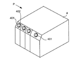
図2は、インクジェット記録装置である液体吐出装置に設けられる一般的な液体収納容器4の一例を示している。ここでは、例えば4色の記録液(イエロー、マゼンタ、シアン及びブラックの記録液)を分離して保持するために、液体収納容器4の内部は4つの空間に仕切られており、空間ごとにその空間につながる注入口401(開口)が設けられている。液体収納容器4は、全体として略直方体に形成されているが、その頂面の1辺に沿ってその辺の近傍を切り落とすことにより、頂面に接続する斜面402が形成されている。注入口401はこの斜面402に形成されている。注入口401は、液体収納容器4の内部に連通する開口であるので、後述するように、液体が入れられたスポイト状の注入容器の先端をこの注入口401内に挿し込むことにより、液体収納容器4に所望の液体を補充することができる。
FIG. 2 shows an example of a general
液体収納容器4から液体が漏出しないように、液体の補充を行うとき以外のときには、注入口401は栓がはめられて密閉される。すなわち、栓は、注入口401に挿入される先端を備えており、注入口401に対して着脱可能な構成となっている。栓は注入操作に際して注入口401から取り外されるが、取り外された栓の紛失等を防ぐために、何らかの手段によって栓は液体収納容器4に接続していることが好ましい。また、栓の先端が注入口401を介して液体収納容器4の内部に挿し込まれるため、栓の先端やその周辺は、液体収納容器4内の液体や注入時に注入口401に付着した液体によって、しばしば汚れた状態となる。そこで本発明に基づく液体収納容器ユニットは、支持部材によって栓を液体収納容器4に接続するとともに、注入操作に際し、栓を注入口401から取り外すことができ、かつ栓の先端がユーザや注入容器9に触れないように栓が保持されるようにしている。支持部材は、例えは、弾性を有するゴムなどの材料によって形成された成形品であり、注入口401から取り外された栓を弾性的に支持する。好ましくは、栓と支持部材とを一体成形品とする。注入口401から取り外された栓の姿勢は、それが固定されない限り、栓と支持部材の形状や重みによる変形などによって決まることになる。この液体収納容器ユニットでは、液体を補充する際に補充を行う作業者の手や補充に用いる注入容器に触れにくいような姿勢で栓を支持するように、支持部材を構成する。具体的には、注入作業のために栓が注入口401を開放して待機しているときに、栓がそのような姿勢となるように、支持部材を形成するか、栓がそのような姿勢を保つようにする何らかの手段を設けるようにする。
なお、支持部材は液体収納容器4に接続されるような構成に限定されず、栓とは別の部材に接続されていればよく、例えば液体吐出装置本体に接続されていてもよい。
In order to prevent the liquid from leaking out from the
The support member is not limited to a configuration that is connected to the
結局、本発明に基づく液体収納容器ユニットでは、栓は、少なくとも、注入口401を塞ぐ第1の状態と、液体を注入する作業のために注入口401を開放して待機する第2の状態と、をとることができる。第2の状態では、栓の先端が作業者の手や補充に用いる注入容器に触れにくいような姿勢となる。このような姿勢には、具体的には、例えば、栓の先端が支持部材の方向を向くことや、あるいは、力がかからない状態で、栓が、支持部材が液体収納容器に接続する位置と注入口との間にあることが含まれる。
Eventually, in the liquid container unit according to the present invention, the stopper includes at least a first state in which the
以下、本発明に基づく液体収容容器ユニットについて、具体的な実施形態に基づいて説明する。ただし以下に説明する例における構成部品の寸法、材質、形状、それらの相対配置などは、装置の構成や各種条件により適宜変更されるべきものであり、本発明の範囲を限定する趣旨のものではない。 Hereinafter, the liquid container unit according to the present invention will be described based on specific embodiments. However, the dimensions, materials, shapes, relative arrangements, and the like of the components in the examples described below should be changed as appropriate according to the configuration of the apparatus and various conditions, and are not intended to limit the scope of the present invention. Absent.
(第1の実施形態)
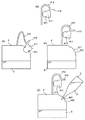
図3は、第1の実施形態の液体収納容器ユニットを示す図である。図3において、(a)は一体化した栓411と支持部材412とを示す模式断面図であり、(b)は注入口401が栓411で閉じられている状態を示し、(c)は注入口401から栓411を取り外した状態を示している。さらに(d)は、注入容器9の先端を注入口401に挿し込んで液体5を液体収納容器4に注入する作業を行っているときの状態を示している。図3(b)〜(d)は、いずれも、液体収納容器4を図2の矢印P方向から見た断面図として描かれている。
(First embodiment)
FIG. 3 is a diagram illustrating the liquid storage container unit according to the first embodiment. 3A is a schematic cross-sectional view showing the
図3(a)に示すように、栓411と支持部材412は、ゴムなどの弾性材料によって一体的に成形されている。支持部材412は、湾曲を有する形状に、例えば、力がかからない状態で逆U字形の形状に成形されており、U字の一方の端部に栓411が設けられ、他方の端部はそのまま延長して固定端として液体収納容器4の頂面に接合している(図3(c)参照)。栓411は液体収納容器4の注入口401を塞ぐためのものであり、先端側がテーパー形状となっている略円柱状に形成されている。栓411の側面には、注入口401と嵌合する円周溝413が形成されている。栓411と注入口401との十分な嵌め合いを確保できるのであれば、円周溝413を必ずしも設ける必要はない。栓411が注入口401に嵌め込まれたとき、すなわち第1の状態にあるときには、図3(b)に示すように、円周溝413から先端側の領域が液体収納容器4の内部に位置することとなる。この栓411の先端側の領域は、液体収納容器4内の液体5あるいは液体5の注入時に注入口401の付近に付着した液体5によって汚されやすい領域である。支持部材412は、栓411の根元側の位置で栓411に接続しており、この位置には、作業者が栓411を操作するときにつまむつまみ部415も設けられている。本実施形態では、図3(c)に示すように栓411が注入口401から取り外されて栓411には重力以外の力が作用しないときが、注入作業のために栓が待機する第2の状態と言うことになる。このとき、栓411の先端は、支持部材412の内側を向いている。ここで支持部材412の内側とは、逆U字型の湾曲に形成された支持部材412において、湾曲の内側面、すなわちU字の内側面のことを指す。
As shown in FIG. 3A, the
本実施形態の液体収納容器ユニットでは、図3(b)に示すように、栓411によって注入口401を塞ぐときには、支持部材412は元の形状から引き伸ばした状態となっている。これに対して、図3(c)に示すように、注入口401から栓411を取り外したときには、支持部材412は元の形状に戻って栓411の先端は支持部材412の内側を向く。作業者は、つまみ部415を持って栓411を動かし、栓411によって注入口401を塞いだり、注入口401から栓411を取り外したりすることができる。図3(d)は注入容器9によって液体収納容器4内に液体5を注入する状態を示しているが、栓411の先端は、支持部材412の内側を向いており、注入口401の側に向けては露出していない。したがって、注入作業に際して作業者の手や注入容器9が栓411に付着した液体によって汚されにくい。また本実施形態では、注入口401から取り外された状態では、栓411は、注入口401よりも液体収納容器4の頂面の中央側に位置している。
In the liquid storage container unit of the present embodiment, as shown in FIG. 3B, when the
また、本実施形態の液体収納容器ユニットでは、図3(c)に示すように注入口401から栓411が取り外された状態で、図3(b)に示す栓411が注入口401に取り付けられた状態よりも、栓411の先端が支持部材412の内側面に近づいている。したがって、注入作業に際して作業者の手や注入容器9が栓411に付着した液体によって汚されにくい。さらに、本実施形態の液体収納容器ユニットでは、図3(c)に示すように注入口401から栓411が取り外された状態では、栓の先端が支持部材412の内側面を向いている。なお、「支持部材の内側面を向く」とは、栓の先端と支持部材の内側面とが互いに沿う状態に限らず、栓の先端と支持部材の内側面とがなす内側の角度が90度より小さい状態であればよい。このように、栓411の先端が支持部材412の内側面を向いており、注入口401の側に向けては露出していないため、注入作業に際して作業者の手や注入容器9が栓411に付着した液体によって汚されることをより抑制することができる。
In the liquid container unit of the present embodiment, the
なお、栓411の先端が接触することにより支持部材412の内側が仮に液体5によって汚れたとしても、支持部材412の内側は栓411によって作業者の手から隔てられているので、2次的な汚れの発生を防止することも期待できる。以下に説明する各実施形態も、栓の先端が接触することによって汚される可能性がある部分が作業者の手などから隔てられており、2次的な汚れの発生を防ぐ可能性があるという点で、この第1の実施形態と共通している。
Even if the inside of the
(比較例)
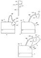
ここで、第1の実施形態の液体収納容器ユニットの効果をより明確に示すために、本発明に基づかない液体収納容器ユニットについて、図4を用いて説明する。図4に示した液体収納容器ユニットは、第1の実施形態のものと同様のものであるが、栓411と一体的に成形されて液体収納容器4に接続する支持部材492として、図4(a)に示すように、力がかからない状態で直線状となるものを使用している。図4(a)〜(d)は、それぞれ、第1の実施形態の液体収納容器ユニットに関する図3(a)〜(d)と同様の図である。栓411によって注入口401を塞ぐときは、図4(b)に示すように、支持部材492は、元の形状から折り曲げた状態となっている。一方、栓411が注入口401から取り外されたときは、図4(c)に示すように、支持部材492はその弾性力によりほぼ直線状に延びるが、栓411の質量のために、先端が下方に垂れ下がるようになる。その結果、栓411の先端部分は、注入口401から見て液体収納容器4の外側に向いて斜め上方の位置で下方を向いて露出することとなる。この栓411の位置は、図4(d)に示すように、液体収納容器4に液体5を注入する際に注入容器9や作業者の手と干渉する位置であり、その結果、比較例では、注入作業時に作業者の手や注入容器9が汚されやすい。
(Comparative example)
Here, in order to show the effect of the liquid container unit of the first embodiment more clearly, a liquid container unit that is not based on the present invention will be described with reference to FIG. The liquid container unit shown in FIG. 4 is the same as that of the first embodiment, but as a supporting
(第2の実施形態)
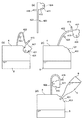
上述した第1の実施形態では、力がかからない状態で支持部材412が逆U字型の形状となるように成形されていたが、直線状の支持部材を用いても本発明に基づく液体収納容器ユニットを構成することができる。図5は第2の実施形態の液体収納容器ユニットを示しており、図5(a)〜(d)は、それぞれ、第1の実施形態の液体収納容器ユニットに関する図3(a)〜(d)と同様の図である。ここでは、図5(a)に示されるように、栓421として、第1の実施形態での栓411と同様のものであるが、先端の中央にボス穴状の凹部424が設けられているものが用いられている。栓421は、直線状に形成された支持部材422と一体的に成形されて支持部材422を介して液体収納容器4の頂面に接続している。支持部材422の内側の中央部には、栓421の凹部424と嵌合可能なボス状の凸部423が設けられている。栓421によって注入口401を塞ぐときは、図5(b)に示すように、支持部材422は、元の形状から折り曲げた状態となっている。この実施形態では、図5(d)に示すように、栓421を取り外したときに支持部材422側の凸部423に栓421の凹部424を嵌合させることで、栓421の先端を支持部材422の内側に向けた状態で栓421を支持部材422に固定することができる。すなわち、栓411は、注入口401とは別の部分である支持部材422の一部に固定可能な構成となっている。図5(d)に示す状態は、注入作業のために栓が待機する第2の状態である。このとき、第1の実施形態と同様に、栓421は、注入口401よりも液体収納容器4の頂面の中央側に位置することになる。この実施形態でも、図5(d)に示すように、栓421を取り外して栓421を支持部材422に固定したときに、栓421の先端は注入口401の側には向けて露出しておらず、栓421の先端側を作業者の手や注入容器9から隔てることができる。したがって、注入作業に際し、作業者の手や注入容器9は栓421に付着した液体によって汚されにくい。
(Second Embodiment)
In the first embodiment described above, the
また、本実施形態の液体収納容器ユニットでは、図5(d)に示すように、栓421の先端が支持部材422に固定された状態で、支持部材422は湾曲されている。そして、この状態では、図6(b)に示す栓421が注入口401に取り付けられた状態よりも、栓421の先端が支持部材422の内側に近づいている。したがって、注入作業に際して作業者の手や注入容器9が栓421に付着した液体によって汚されにくい。さらに、本実施形態の液体収納容器ユニットでは、図5(d)に示すように421の先端が支持部材422に固定された状態では、栓の先端が支持部材422の内側面を向いている。なお、「支持部材の内側面を向く」とは、栓の先端と支持部材の内側面とが互いに沿う状態に限らず、栓の先端と支持部材の内側面とがなす内側の角度が90度より小さい状態であればよい。このように、栓421の先端が支持部材422の内側面を向いており、注入口401の側に向けては露出していないため、注入作業に際して作業者の手や注入容器9が栓421に付着した液体によって汚されることをより抑制することができる。
Further, in the liquid storage container unit of the present embodiment, as shown in FIG. 5D, the
(第3の実施形態)
図6は第3の実施形態の液体収納容器ユニットを示しており、図6(a)〜(d)は、それぞれ、第1の実施形態の液体収納容器ユニットに関する図3(a)〜(d)と同様の図である。第3の実施形態においても第2の実施形態と同様に、直線状の支持部材432を用いているが、第2の実施形態とは異なり、図6(a)に示すように、支持部材432の内側の中央部にはボス穴状の穴または凹部434が形成されている。それに対応して、支持部材432と一体のものとして形成される栓431では、その先端の中央部にボス状の凸部443が設けられている。栓431によって注入口401を塞ぐときは、図6(b)に示すように、支持部材432は、元の形状から折り曲げた状態となっている。この実施形態では、図6(c)に示すように、栓431を取り外したときに支持部材432側の凹部434に栓431の凸部433を嵌合させることで、栓431の先端を支持部材432の内側に向けた状態で栓431を支持部材432に固定することができる。この実施形態でも、図6(d)に示すように、第2の実施形態と同様に、栓431を取り外したときに、栓431の先端側を作業者の手や注入容器9から隔てることができる。したがって、注入作業に際して作業者の手や注入容器9が栓431に付着した液体によって汚されにくい。
(Third embodiment)
FIG. 6 shows a liquid storage container unit according to the third embodiment, and FIGS. 6A to 6D respectively show FIGS. 3A to 3D regarding the liquid storage container unit according to the first embodiment. ). Also in the third embodiment, a
第2及び第3の実施形態の趣旨は、栓の先端が露出することを防ぎながら栓を支持部材に固定できるようにすることである。したがって、第2及び第3の実施形態に示されるように、相互に嵌合する凹部と凸部とが逆の位置に設けられていてもよいし、嵌合ではなく、引掛けやフリーストップのような機構で栓の先端を支持部材に固定するようにしてもよい。言い換えれば、第2及び第3の実施形態は、支持部材に栓を固定するために、栓の先端に第1の構造を形成し、支持部材に第2の構造を形成して、第1の構造と第2の構造とが相互に嵌合または係合可能とするものである。 The gist of the second and third embodiments is to enable the stopper to be fixed to the support member while preventing the tip of the stopper from being exposed. Therefore, as shown in the second and third embodiments, the recessed portion and the protruding portion that are fitted to each other may be provided at opposite positions, and not the fitting but the hook or free stop. You may make it fix the front-end | tip of a stopper to a support member with such a mechanism. In other words, in the second and third embodiments, in order to fix the plug to the support member, the first structure is formed at the tip of the plug, and the second structure is formed at the support member. The structure and the second structure can be fitted or engaged with each other.
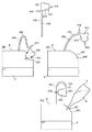
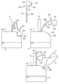
(第4の実施形態)
図7は第4の実施形態の液体収納容器ユニットを示しており、図7(a)〜(d)は、それぞれ、第2の実施形態の液体収納容器ユニットに関する図5(a)〜(d)と同様の図である。第4の実施形態の液体収納容器ユニットは、第2の実施形態のものと同様のものであるが、栓421と一体的に成形される支持部材442の内側に設けられるボス状の凸部443の側面に凹凸が形成されている点で、第2の実施形態のものと異なっている。第4の実施形態では、凸部443の側面の凹凸によって栓421をより強固に固定することができるので、支持部材442の弾性によって栓421が外れることなどの可能性が減少する。したがって、不用意に作業者の手や注入容器9を汚すこともより起こりにくくなる。
(Fourth embodiment)
FIG. 7 shows the liquid storage container unit of the fourth embodiment, and FIGS. 7A to 7D are views of the liquid storage container unit of the second embodiment, respectively. ). The liquid storage container unit of the fourth embodiment is the same as that of the second embodiment, but a boss-like
(第5の実施形態)
図8は第5の実施形態の液体収納容器ユニットを示しており、図8(a)〜(d)は、それぞれ、第2の実施形態の液体収納容器ユニットに関する図5(a)〜(d)と同様の図である。図5に示した第2の実施形態の液体収納容器ユニットでは、栓421を支持部材422に固定するときに、つまみ部415をつかんで栓421を支持部材422の内側に押し付ける。しかしながらこのとき、支持部材422が変形し、支持部材422の凸部423に栓421の凹部424を嵌合させる作業の作業性が低下することがある。そこで第5の実施形態の液体収納容器ユニットでは、第2の実施形態の液体収納容器ユニットにおいて、支持部材422の背面側に、剛性を有するバックアップ部材10を配置している。バックアップ部材10は、液体収納容器4の頂面からほぼ垂直に延びる例えば角柱状の部材であり、支持部材422の背面(注入口401とは反対側となる面)に接するように設けられている。バックアップ部材10は、支持部材422が液体収納容器4に接続する位置から注入口401とは反対側となる方向に、支持部材422が変形することを防止するものであり、第2の状態にあるときに支持部材422が当接する部材である。バックアップ部材10を設けたことにより、図8(d)に示すように、栓421を支持部材422に固定する際に、支持部材422が後ろに逃げるような変形をすることをバックアップ部材10が妨げるので、より容易に固定することができる。
(Fifth embodiment)
FIG. 8 shows a liquid storage container unit according to the fifth embodiment. FIGS. 8A to 8D are views of the liquid storage container unit according to the second embodiment, respectively. ). In the liquid storage container unit of the second embodiment shown in FIG. 5, when the
(第6の実施形態)
図9は第6の実施形態の液体収納容器ユニットを示している。図9(a)は第2の実施形態の液体収納容器ユニットに関する図5(a)に対応する図であり、図9(b)は図9(a)に対応した支持部材452と栓421の正面図であり、図9(c)〜(e)は、それぞれ、図5(b)〜(d)と同様の図である。第6の実施形態の液体収納容器ユニットは、第5の実施形態の液体収納容器ユニットにおいて、支持部材に凸部を設ける代わりに、栓421の凹部424に嵌合する凸部453をバックアップ部材10に設けたものである。すなわち、栓421は、注入口401とは別の部分であるバックアップ部材10の一部に固定可能な構成となっている。バックアップ部材10に凸部453が設けられていることにより、栓421と一体的に成形される支持部材452には、凸部453が貫通するスリット454が形成されている。栓421による注入口401の開閉に伴う支持部材452の変形を妨げないように、スリット454は、支持部材452の長手方向に沿って十分な長さで設けられている。本実施形態でも栓421を支持部材452に固定する際に、支持部材452が後ろに逃げるような変形をすることをバックアップ部材10が妨げるので、より容易に固定することができる。
(Sixth embodiment)
FIG. 9 shows a liquid container unit according to the sixth embodiment. FIG. 9A is a view corresponding to FIG. 5A relating to the liquid storage container unit of the second embodiment, and FIG. 9B is a view of the
(第7の実施形態)
上述した各実施形態では、栓と一体的に成形されて栓を液体収納容器4に接続する支持部材の固定端の位置は、液体収納容器4の頂面であったが、支持部材の固定端の位置と注入口401との位置関係は上述したものに限定されるものではない。図10に示す第7の実施形態の液体収納容器ユニットでは、第2の実施形態で示したものと同じ支持部材422及び栓を421を使用しつつ、液体収納容器4の側面であって注入口401の下方となる位置で支持部材422を液体収納容器4に接続している。図10(a)〜(d)は、それぞれ、第2の実施形態の液体収納容器ユニットに関する図5(a)〜(d)と同様の図である。本実施形態においても、栓421の先端を支持部材422の内側に向けた状態で栓421を支持部材422に固定することができる。したがって、注入作業に際して作業者の手や注入容器9が栓421に付着した液体によって汚されにくい。
(Seventh embodiment)
In each of the embodiments described above, the position of the fixed end of the support member that is molded integrally with the plug and connects the plug to the
(第8の実施形態)
上述した第1乃至第8の実施形態では、栓を注入口から取り外したときに栓の先端が支持部材の内側を向くようにしていたが、本発明に基づく液体収納容器ユニットはそれに限られるものではない。例えば、栓の先端が支持部材の内側を向いていなくても、栓を取り外したときに注入口401と比べて栓の先端が支持部材と液体収納容器4との接続位置により接近するようにすることにより、作業者の手や注入容器9への汚れの付着を防止することができる。図11は第8の実施形態の液体収納容器ユニットを示しており、、図11(a)〜(d)は、それぞれ、第1の実施形態の液体収納容器ユニットに関する図3(a)〜(d)と同様の図である。
(Eighth embodiment)
In the first to eighth embodiments described above, when the stopper is removed from the inlet, the tip of the stopper faces the inside of the support member. However, the liquid storage container unit according to the present invention is limited thereto. is not. For example, even if the distal end of the stopper does not face the inside of the support member, the distal end of the stopper is closer to the connection position between the support member and the
本実施形態では、栓411と一体的に成形される支持部材462の形状を工夫することにより、注入口401から取り外したときに、栓411が注入口401からみて液体収納容器4の頂面の中央側に位置するようにしたものである。具体的には、第1の実施形態における逆U字型に成形された支持部材において、U字の両端のうち栓411が接続する方の端部をさらに水平方向に曲げた形状を有する支持部材462を使用する。このように折り畳まれた形状で成形された支持部材462を用いることにより、取り外し状態において栓411の先端は、図11(c)に示すように、液体収納容器4の頂面を向いている。注入口401を栓411で塞ぐときは、図11(b)に示すように、支持部材462は元の形状から引き伸ばされた状態となっている。そして、栓411を取り外したときに、栓411の先端が支持部材462の液体収納容器4側の固定端に近付きながら、支持部材462は元の形状に戻る。本実施形態においても、図11(d)に示すように、栓411を注入口401から取り外したときに栓411の先端が露出しないので、注入作業に際して作業者の手や注入容器9を汚しにくい。
In the present embodiment, by devising the shape of the
本実施形態において、取り外し状態での栓411の先端は必ずしも液体収納容器4の頂面を向いている必要はなく、より好ましくは、第1の実施形態のように支持部材の内側を向いていてもよい。ただし、図3に示すように支持部材の内側に向けて栓411の先端が大きく曲げられる必要はなく、栓411を取り外したときに栓411の先端が注入口401から支持部材462の固定端側に近づくようにすればよい。このように栓411の先端が支持部材462の固定端に近づくようにすることにより、液体5の注入作業時に作業者の手や注入容器9を汚されにくいう効果を発揮することができる。
In the present embodiment, the distal end of the
(第9の実施形態)
図12は第9の実施形態の液体収納容器ユニットを示しており、図12(a)〜(d)は、それぞれ、第2の実施形態の液体収納容器ユニットに関する図5(a)〜(d)と同様の図である。図5に示した第2の実施形態の液体収納容器ユニットでは、栓421を固定するために支持部材422に設けたボス状の凸部423に対して栓421の凹部424を嵌合させていたが、栓421を固定させる構造はこれに限られるものではない。図12に示す第9の実施形態の液体収納容器ユニットでは、栓421の先端に設けられた凹部424に嵌合するボス状の凸部473が、液体収納容器4の頂面に形成されている。栓421と一体的に成形されて栓421を液体収納容器4に接続する支持部材472には、凹部424に嵌合する凸部は形成されていない。支持部材472は、第2の実施形態のものと同様に、直線状に形成されている。本実施形態では、栓421を注入口401から取り外したときに、図12(d)に示すように、栓421の凹部424を凸部473に嵌合させることで、注入口401と支持部材472の固定端の位置との間で栓421を固定することができる。栓421が固定される位置は、注入口401から見て液体収納容器4の頂面の中央側の位置であり、これにより、栓421を取り外したときに栓421の先端を露出させないようにすることができる。したがって本実施形態においても、液体5の注入作業を行う際に、作業者の手や注入容器9が汚されることを防ぐことができる。
(Ninth embodiment)
FIG. 12 shows a liquid storage container unit according to the ninth embodiment, and FIGS. 12A to 12D respectively show FIGS. 5A to 5D related to the liquid storage container unit according to the second embodiment. ). In the liquid container unit of the second embodiment shown in FIG. 5, the
本実施形態の趣旨は、栓421の先端が露出することを防ぎながら、栓421を注入口401と支持部材472の固定端との間で固定することにある。したがって、栓の側に凸部を設け、液体収納容器4の頂面に凹部を形成するようにしてもよく、さらには、凸部と凹部による嵌合ではなく、引掛けやフリーストップのような機構で栓を固定できるようにしてもよい。言い換えれば、第9の実施形態は、液体収納容器に栓を固定するために、栓の先端に第1の構造を形成し、液体収納容器に第2の構造を形成して、第1の構造と第2の構造とが相互に嵌合または係合可能とするものである。
The gist of the present embodiment is to fix the
以上説明した各実施形態によれば、液体収納容器4に液体5を注入するときに、作業者の手や注入容器9を汚しにくい液体収容容器ユニットを提供することができる。
According to each embodiment described above, when the
4 液体収納容器
401 注入口
411,421,431 栓
412,432,442,452,462 支持部材
4
Claims (17)
前記注入口を塞ぐための先端を備え、前記注入口に取り外し可能に取り付けられる栓と、
前記栓と前記栓とは別の部材とを接続して前記栓を弾性的に支持する支持部材と、
を有し、
前記栓は、少なくとも、前記注入口を塞ぐ第1の状態と、前記液体を注入する作業のために前記注入口を開放して待機する第2の状態と、をとることができ、
前記栓の先端は、前記第2の状態において前記支持部材の方向を向く、液体収納容器ユニット。 A liquid storage container having an inlet for injecting liquid;
A stopper provided with a tip for closing the inlet, and removably attached to the inlet;
A support member that elastically supports the stopper by connecting the stopper and a member different from the stopper;
Have
The stopper can take at least a first state in which the inlet is closed and a second state in which the inlet is opened for standby to inject the liquid.
The tip of the stopper is a liquid storage container unit that faces the support member in the second state.
前記第2の状態において前記栓を固定するために、前記第1の構造と前記第2の構造とが相互に嵌合または係合可能である、請求項1に記載の液体収納容器ユニット。 A first structure formed at the tip of the stopper; and a second structure formed on the support member;
The liquid container unit according to claim 1, wherein the first structure and the second structure can be fitted or engaged with each other in order to fix the stopper in the second state.
前記注入口を塞ぐための先端を備え、前記注入口に取り外し可能に取り付けられる栓と、
前記栓と前記栓とは別の部材とを接続して前記栓を弾性的に支持する支持部材と、
を有し、
前記栓は、少なくとも、前記注入口を塞ぐ第1の状態と、前記液体を注入する作業のために前記注入口を開放して待機する第2の状態と、をとることができ、
前記栓の先端は、前記第2の状態において、前記支持部材が前記別の部材に接続する位置と前記注入口との間にある、液体収納容器ユニット。 A liquid storage container having an inlet for injecting liquid;
A stopper provided with a tip for closing the inlet, and removably attached to the inlet;
A support member that elastically supports the stopper by connecting the stopper and a member different from the stopper;
Have
The stopper can take at least a first state in which the inlet is closed and a second state in which the inlet is opened for standby to inject the liquid.
In the second state, the tip of the stopper is a liquid container unit between the inlet and the position where the support member connects to the other member.
前記第2の状態において前記栓を固定するために、前記第1の構造と前記第2の構造とが相互に嵌合または係合可能である、請求項5に記載の液体収納容器ユニット。 A first structure formed at the tip of the stopper; and a second structure formed on the other member;
The liquid container unit according to claim 5, wherein the first structure and the second structure can be fitted or engaged with each other in order to fix the stopper in the second state.
前記開口に対して着脱可能であり、前記開口に挿入される先端を備える栓と、
前記栓と前記栓とは別の部材とを接続し、前記栓を支持する支持部材と、
を有し、
前記支持部材は湾曲を有する形状に成形されており、
前記栓が前記開口から取り外された状態で、前記栓が前記開口に取り付けられた状態よりも前記栓の先端が前記支持部材の湾曲の内側面に近づくこと特徴とする液体収納容器ユニット。 A liquid storage container having an opening;
A stopper that is detachable from the opening and has a tip inserted into the opening;
A support member for connecting the stopper and a member different from the stopper, and supporting the stopper;
Have
The support member is formed into a curved shape,
The liquid container unit, wherein the tip of the plug is closer to the curved inner surface of the support member when the stopper is removed from the opening than when the stopper is attached to the opening.
前記開口に対して着脱可能であり、前記開口に挿入される先端を備える栓と、
前記栓と前記栓とは別の部材とを接続し、前記栓を支持する支持部材と、
を有し、
前記栓は前記開口とは別の部分に固定可能であり、
前記栓が前記別の部分に固定された状態で、前記支持部材は湾曲され、前記栓が前記開口に取り付けられた状態よりも前記栓の先端が前記支持部材の湾曲の内側面に近づくことを特徴とする液体収納容器ユニット。 A liquid storage container having an opening;
A stopper that is detachable from the opening and has a tip inserted into the opening;
A support member for connecting the stopper and a member different from the stopper, and supporting the stopper;
Have
The stopper can be fixed to a part different from the opening,
The support member is curved in a state where the stopper is fixed to the other portion, and the tip of the stopper is closer to the curved inner surface of the support member than in the state where the stopper is attached to the opening. A liquid storage container unit.
The liquid storage container unit according to claim 1, wherein a supply tube that supplies the liquid is connected to a liquid discharge head provided in the liquid discharge apparatus.
Priority Applications (2)
| Application Number | Priority Date | Filing Date | Title |
|---|---|---|---|
| JP2016084445A JP2017193105A (en) | 2016-04-20 | 2016-04-20 | Liquid storage container unit |
| US15/479,816 US9914305B2 (en) | 2016-04-20 | 2017-04-05 | Liquid storage container unit |
Applications Claiming Priority (1)
| Application Number | Priority Date | Filing Date | Title |
|---|---|---|---|
| JP2016084445A JP2017193105A (en) | 2016-04-20 | 2016-04-20 | Liquid storage container unit |
Publications (1)
| Publication Number | Publication Date |
|---|---|
| JP2017193105A true JP2017193105A (en) | 2017-10-26 |
Family
ID=60089294
Family Applications (1)
| Application Number | Title | Priority Date | Filing Date |
|---|---|---|---|
| JP2016084445A Pending JP2017193105A (en) | 2016-04-20 | 2016-04-20 | Liquid storage container unit |
Country Status (2)
| Country | Link |
|---|---|
| US (1) | US9914305B2 (en) |
| JP (1) | JP2017193105A (en) |
Cited By (2)
| Publication number | Priority date | Publication date | Assignee | Title |
|---|---|---|---|---|
| CN109720096A (en) * | 2017-10-30 | 2019-05-07 | 精工爱普生株式会社 | Latch, liquid accommodation unit |
| JP7516151B2 (en) | 2020-07-29 | 2024-07-16 | キヤノン株式会社 | Recording device |
Families Citing this family (16)
| Publication number | Priority date | Publication date | Assignee | Title |
|---|---|---|---|---|
| US10093105B2 (en) | 2016-04-22 | 2018-10-09 | Canon Kabushiki Kaisha | Liquid storage container and liquid ejection apparatus |
| JP6775992B2 (en) | 2016-04-22 | 2020-10-28 | キヤノン株式会社 | Liquid storage container and liquid discharge device |
| JP6746391B2 (en) | 2016-06-15 | 2020-08-26 | キヤノン株式会社 | Liquid container unit |
| US10399347B2 (en) | 2016-06-29 | 2019-09-03 | Canon Kabushiki Kaisha | Liquid supplying mechanism, and liquid ejection apparatus |
| JP7267708B2 (en) | 2017-10-13 | 2023-05-02 | キヤノン株式会社 | MEMBER HAVING PAD ELECTRODE, INK CARTRIDGE, RECORDING DEVICE |
| CN111194266B (en) | 2017-10-13 | 2021-12-24 | 佳能株式会社 | Member including pad electrode, ink cartridge, and recording apparatus |
| US11077670B2 (en) | 2018-01-30 | 2021-08-03 | Canon Kabushiki Kaisha | Inkjet printing apparatus and ink filling method |
| CN112399920B (en) * | 2018-08-30 | 2023-01-10 | 惠普发展公司,有限责任合伙企业 | Verification mechanism |
| JP7242231B2 (en) | 2018-09-28 | 2023-03-20 | キヤノン株式会社 | Member having pad electrode, recording device |
| JP7154919B2 (en) | 2018-09-28 | 2022-10-18 | キヤノン株式会社 | ink cartridge |
| JP7224830B2 (en) | 2018-09-28 | 2023-02-20 | キヤノン株式会社 | MEMBER HAVING PAD ELECTRODE, INK CARTRIDGE, RECORDING DEVICE |
| JP7199959B2 (en) | 2018-12-26 | 2023-01-06 | キヤノン株式会社 | LIQUID EJECTOR AND METHOD OF CONTROLLING LIQUID EJECTOR |
| JP2022128031A (en) | 2021-02-22 | 2022-09-01 | キヤノン株式会社 | Liquid storage container and liquid discharge device |
| JP2022137621A (en) | 2021-03-09 | 2022-09-22 | キヤノン株式会社 | Liquid storage container and liquid discharge device |
| JP2022166985A (en) | 2021-04-22 | 2022-11-04 | キヤノン株式会社 | Liquid storage container and liquid discharge device |
| JP2022170139A (en) * | 2021-04-28 | 2022-11-10 | キヤノン株式会社 | Liquid storage container and liquid discharge device |
Family Cites Families (40)
| Publication number | Priority date | Publication date | Assignee | Title |
|---|---|---|---|---|
| DE69031666T2 (en) | 1989-01-13 | 1998-04-02 | Canon Kk | Ink jet recording head, ink jet recording device and wiping method therefor |
| DE69033525T2 (en) | 1989-01-28 | 2000-09-14 | Canon K.K., Tokio/Tokyo | Ink jet head, ink tank and ink jet device |
| US5162817A (en) | 1989-01-28 | 1992-11-10 | Canon Kabushiki Kaisha | Ink jet with residual ink detection that compensates for different ink properties |
| JP2675851B2 (en) | 1989-01-28 | 1997-11-12 | キヤノン株式会社 | INKJET RECORDING METHOD AND DEVICE USED FOR THE METHOD |
| JP3133750B2 (en) | 1989-03-24 | 2001-02-13 | キヤノン株式会社 | Ink jet cartridge and ink jet recording apparatus using the same |
| US5355158A (en) | 1990-01-11 | 1994-10-11 | Canon Kabushiki Kaisha | Ink jet apparatus and method of recovering ink jet head |
| JP2944767B2 (en) | 1991-02-06 | 1999-09-06 | キヤノン株式会社 | Ink jet recording device |
| JP2872431B2 (en) | 1991-04-22 | 1999-03-17 | キヤノン株式会社 | Ink jet recording device |
| CA2085550C (en) | 1991-12-19 | 1999-07-06 | Kentaro Yano | Method of controlling an ink-jet recording apparatus according to recording head information, and ink-jet recording apparatus in which the method is implemented |
| JP3021149B2 (en) | 1991-12-19 | 2000-03-15 | キヤノン株式会社 | Ink jet recording means |
| JP3165722B2 (en) | 1992-01-20 | 2001-05-14 | キヤノン株式会社 | Ink jet device |
| DE69333481T2 (en) | 1992-10-09 | 2005-03-24 | Canon K.K. | Ink jet printing head and printing device provided therewith |
| JP3227284B2 (en) | 1992-10-30 | 2001-11-12 | キヤノン株式会社 | Ink jet recording method and ink jet recording head |
| US5606354A (en) | 1993-07-06 | 1997-02-25 | Canon Kabushiki Kaisha | Recovery mechanism for adjustable ink jet head |
| US5646655A (en) | 1993-08-31 | 1997-07-08 | Canon Kabushiki Kaisha | Recording apparatus and temperature detecting method therefor |
| JPH08230205A (en) | 1995-02-28 | 1996-09-10 | Canon Inc | Ink tank protecting method and membur and ink tank having protecting member |
| JPH08290577A (en) | 1995-04-20 | 1996-11-05 | Hitachi Koki Co Ltd | Ink tank |
| JP3880232B2 (en) | 1997-12-25 | 2007-02-14 | キヤノン株式会社 | Liquid supply method, liquid supply system using the liquid supply method, and ink tank |
| JP2001001546A (en) | 1999-06-24 | 2001-01-09 | Canon Inc | Liquid supply system and liquid supply container used in the system |
| US6505923B1 (en) | 1999-06-24 | 2003-01-14 | Canon Kabushiki Kaisha | Liquid supply system, liquid supply container and negative pressure generating member container used for the same system, and ink jet recording apparatus using the same system |
| US8529035B2 (en) | 2010-02-26 | 2013-09-10 | Canon Kabushiki Kaisha | Ink jet cartridge and manufacturing method of ink jet cartridge |
| JP2011177917A (en) | 2010-02-26 | 2011-09-15 | Canon Inc | Method of manufacturing inkjet cartridge |
| JP5340240B2 (en) | 2010-04-02 | 2013-11-13 | キヤノン株式会社 | TANK AND PRINTER HAVING THE SAME |
| US8529037B2 (en) | 2011-02-03 | 2013-09-10 | Canon Kabushiki Kaisha | Ink tank and production process of ink tank |
| JP5804727B2 (en) | 2011-02-25 | 2015-11-04 | キヤノン株式会社 | Method and apparatus for manufacturing liquid storage container |
| JP5780785B2 (en) | 2011-03-11 | 2015-09-16 | キヤノン株式会社 | Negative pressure generating member insertion method and negative pressure generating member insertion device |
| JP5615392B2 (en) | 2012-02-23 | 2014-10-29 | キヤノン株式会社 | Liquid storage container and apparatus capable of mounting the same |
| JP5979906B2 (en) | 2012-02-23 | 2016-08-31 | キヤノン株式会社 | Liquid storage container and apparatus capable of mounting the same |
| EP3047976B1 (en) | 2013-09-18 | 2019-11-06 | Canon Kabushiki Kaisha | Ink cartridge |
| RU2654423C2 (en) | 2013-09-18 | 2018-05-17 | Кэнон Кабусики Кайся | Ink cartridge and inkjet printer |
| JP2015077731A (en) | 2013-10-17 | 2015-04-23 | キヤノン株式会社 | Ink filling device and ink filling method |
| JP6415114B2 (en) | 2014-05-30 | 2018-10-31 | キヤノン株式会社 | Liquid storage unit, liquid discharge apparatus using the same, and method for removing bubbles from liquid storage unit |
| JP6355442B2 (en) | 2014-06-10 | 2018-07-11 | キヤノン株式会社 | Liquid filling method for liquid container |
| US9375938B2 (en) | 2014-06-27 | 2016-06-28 | Canon Kabushiki Kaisha | Ink cartridge and ink jet printing apparatus |
| JP6385163B2 (en) | 2014-06-27 | 2018-09-05 | キヤノン株式会社 | Liquid storage container and liquid discharge device |
| JP6432261B2 (en) * | 2014-09-30 | 2018-12-05 | ブラザー工業株式会社 | Liquid consumption device |
| JP6579800B2 (en) | 2015-05-25 | 2019-09-25 | キヤノン株式会社 | Inkjet recording device |
| JP6308989B2 (en) | 2015-09-30 | 2018-04-11 | キヤノン株式会社 | Liquid storage container and liquid discharge device |
| JP6602160B2 (en) | 2015-10-30 | 2019-11-06 | キヤノン株式会社 | Liquid ejection device and head |
| JP6611564B2 (en) | 2015-10-30 | 2019-11-27 | キヤノン株式会社 | Liquid storage bottle and liquid storage bottle package |
-
2016
- 2016-04-20 JP JP2016084445A patent/JP2017193105A/en active Pending
-
2017
- 2017-04-05 US US15/479,816 patent/US9914305B2/en active Active
Cited By (3)
| Publication number | Priority date | Publication date | Assignee | Title |
|---|---|---|---|---|
| CN109720096A (en) * | 2017-10-30 | 2019-05-07 | 精工爱普生株式会社 | Latch, liquid accommodation unit |
| CN109720096B (en) * | 2017-10-30 | 2021-11-30 | 精工爱普生株式会社 | Plug member and liquid containing unit |
| JP7516151B2 (en) | 2020-07-29 | 2024-07-16 | キヤノン株式会社 | Recording device |
Also Published As
| Publication number | Publication date |
|---|---|
| US20170305164A1 (en) | 2017-10-26 |
| US9914305B2 (en) | 2018-03-13 |
Similar Documents
| Publication | Publication Date | Title |
|---|---|---|
| JP2017193105A (en) | Liquid storage container unit | |
| JP6746391B2 (en) | Liquid container unit | |
| US9994030B2 (en) | Liquid supply apparatus and liquid container | |
| JP5842616B2 (en) | Liquid cartridge, image forming apparatus | |
| JP6264328B2 (en) | Liquid refill container | |
| JP6700719B2 (en) | Liquid ejection device and head | |
| JP2012035489A (en) | Fluid storage container | |
| JP2016172358A (en) | Liquid container, and liquid injection device | |
| JP6019576B2 (en) | Image forming apparatus | |
| US9969172B2 (en) | Liquid consuming apparatus and ink-jet printer | |
| JP2023096144A (en) | recording device | |
| JP2015196300A (en) | cartridge case | |
| JP2019130767A (en) | Liquid tank and liquid injection device | |
| JP5776242B2 (en) | Cap, liquid container, and liquid ejection system | |
| US9994039B2 (en) | Liquid ejecting apparatus | |
| JP6926950B2 (en) | Plug member, liquid storage unit | |
| JP6969162B2 (en) | Waste liquid container and liquid injection device | |
| JP2017124542A (en) | Recording device | |
| JP2014024349A (en) | Liquid cartridge and image forming device | |
| JP6972621B2 (en) | Liquid consuming device | |
| JP2022128031A (en) | Liquid storage container and liquid discharge device | |
| JP2018027630A (en) | Recording device | |
| JP2020146921A (en) | Liquid jet device | |
| US20240269987A1 (en) | Liquid storage container and printing apparatus | |
| JP6065469B2 (en) | Liquid injection system |