JP2017193083A - Method of manufacturing connector terminal, and metal molding for insert molding used for the method - Google Patents
Method of manufacturing connector terminal, and metal molding for insert molding used for the method Download PDFInfo
- Publication number
- JP2017193083A JP2017193083A JP2016083673A JP2016083673A JP2017193083A JP 2017193083 A JP2017193083 A JP 2017193083A JP 2016083673 A JP2016083673 A JP 2016083673A JP 2016083673 A JP2016083673 A JP 2016083673A JP 2017193083 A JP2017193083 A JP 2017193083A
- Authority
- JP
- Japan
- Prior art keywords
- mold
- terminal
- insert molding
- connector terminals
- connector
- Prior art date
- Legal status (The legal status is an assumption and is not a legal conclusion. Google has not performed a legal analysis and makes no representation as to the accuracy of the status listed.)
- Pending
Links
Images


Abstract
Description
本発明は、例えば電子機器の回路接続に使用するコネクタ等を製造する方法に係わり、特に高価なフープ材金属の使用を抑え、コストを低減させて、効率よく生産することができるだけでなく、多様化するコネクタ端子類の製造においても、自由度を阻害することのないコネクタ端子類の製造法及びインサート成形用金型に関するものである。 The present invention relates to a method of manufacturing a connector used for circuit connection of an electronic device, for example. In particular, the invention can not only suppress the use of expensive hoop material metal, reduce cost, and produce efficiently, but also variously. The present invention also relates to a method of manufacturing connector terminals and a mold for insert molding that do not hinder the degree of freedom in manufacturing connector terminals to be manufactured.
コネクタ等の端子接点部には電気伝導度が高く、尚且つ、高い耐摩耗性及び耐腐食性が要求される。このため、金などのように、電気伝導度が高く、高い耐摩耗性及び耐腐食性を有する高価な希少金属又はそれらの合金が、コネクタ端子自体又はコネクタ端子のメッキとして使用されている。 Terminal contact portions such as connectors are required to have high electrical conductivity and high wear resistance and corrosion resistance. For this reason, expensive rare metals or their alloys, such as gold, having high electrical conductivity and high wear resistance and corrosion resistance, are used as connector terminals themselves or connector terminal plating.
これにより、キャリアであるフープ材を端子と同じ材質のものとした場合には、フープ材の全体を電気伝導度が高く、高い耐摩耗性及び耐腐食性を有する高価な金属で構成することになり、高価な材料であっても接点以外のインサート成形後に不要な端子部分やキャリア部分は廃材として処理せざるを得ないことになっていた。 As a result, when the hoop material as the carrier is made of the same material as the terminal, the entire hoop material is made of an expensive metal having high electrical conductivity and high wear resistance and corrosion resistance. Therefore, even if it is an expensive material, unnecessary terminal portions and carrier portions after insert molding other than contacts have to be treated as waste materials.
このため、本出願人は、電気伝導度が高く、高い耐摩耗性及び耐腐食性を有する高価な金属を使用する部分は、小さな端子列連設片のみとし、キャリアには廉価な薄い金属帯材コイルを使用し、一部にコネクタ端子列を備える構造体及びその成形方法を提案した(特許文献1)。 For this reason, the applicant of the present invention uses only a small terminal row connection piece, and uses an inexpensive thin metal strip for the carrier, where the expensive metal having high electrical conductivity and high wear resistance and corrosion resistance is used. A structure using a material coil and partially including a connector terminal array and a method for forming the structure have been proposed (Patent Document 1).
詳しくは、高価な帯状基板の片側に端子列を延在させて端子帯とし、カッタ等によってこの端子帯の帯状基板を所定の長さの端子列連設片に裁断する。端子帯を裁断して形成した端子列連設片は、所定の間隔で安価な帯材に圧着固定される。この帯材はキャリアとなって端子列連設片を搬送し、端子列連設片の端子列を射出成形金型キャビティ内の所定の位置に誘導される。 Specifically, a terminal row is extended to one side of an expensive strip-shaped substrate to form a terminal strip, and the strip-shaped substrate of the terminal strip is cut into a predetermined length of a row of terminal rows by a cutter or the like. The terminal row continuous piece formed by cutting the terminal band is fixed by crimping to an inexpensive band member at a predetermined interval. The band material serves as a carrier to convey the terminal row continuous piece, and the terminal row of the terminal row continuous piece is guided to a predetermined position in the injection mold cavity.
安価な帯材のキャリアによって端子列が金型に正確に位置付けられると、金型が閉じられ構造体が射出成形される。端子列は帯状基板と一体のまま構造体にインサート成形され、金型を開くと安価な帯材のキャリアは移動して、一部にコネクタ端子列を備える構造体を金型の外に搬出する。 When the terminal row is accurately positioned on the mold by an inexpensive band carrier, the mold is closed and the structure is injection molded. The terminal row is insert-molded into the structure while being integrated with the belt-like substrate, and when the die is opened, the inexpensive carrier of the strip material moves, and the structure body partially including the connector terminal row is carried out of the die. .
最後に構造体と一体になった端子列連設片は上述したように帯材のキャリアから簡単に取り外すことができるので、帯材をコイルに巻き取りながら構造体を回収し、端子列連設片の帯状基板を切り離すものである。 Finally, since the terminal row connecting piece integrated with the structure can be easily removed from the carrier of the strip as described above, the structure is recovered while winding the strip around the coil, and the terminal row is connected. A piece of strip-shaped substrate is cut off.
この一部にコネクタ端子列を備える構造体の提案は、フープ材に高価な金属の使用を抑えることにより、コストを低減させて、効率よく生産することができるものである。一方、近年では、コネクタ端子自体がより小型になり、より端子数が多いものが主流となりつつあり、このような一部にコネクタ端子列を備える構造体及びその成形方法については、より小型なコネクタや、より複雑なコネクタに適用させることが望まれていた。 The proposal of a structure including a connector terminal row in a part thereof can be efficiently produced at a reduced cost by suppressing the use of an expensive metal for the hoop material. On the other hand, in recent years, connector terminals themselves have become smaller, and those having a larger number of terminals are becoming mainstream. Regarding such a structure including a connector terminal array in a part thereof and a method for forming the structure, a smaller connector is used. In addition, it has been desired to be applied to more complicated connectors.
本発明は、フープ材に高価な金属の使用を抑え、コストを低減させて、効率よく生産することができるだけでなく、多様化するコネクタ端子類の製造において、コネクタ構成の自由度を阻害することのないコネクタ端子類の製造法及びインサート成形用金型を得ることを目的とする。 The present invention not only suppresses the use of expensive metal for the hoop material, reduces costs, and can efficiently produce, but also inhibits the degree of freedom of connector configuration in the manufacture of diversified connector terminals. It aims at obtaining the manufacturing method of connector terminals without insert, and the metal mold | die for insert molding.
請求項1に記載された発明に係るコネクタ端子類の製造法は、樹脂が射出される射出ステージを含む複数のステージを循環移動する複数の第1金型と、前記射出ステージにおいて内部に封止される埋設コネクタ端子と共に前記第1金型に型締めされる第2金型とを用いるインサート成形法であって、
前記第1金型及びこの第1金型に型締される第2金型は、2つ以上のインサート成形品の組が製造されるものであり、
前記埋設コネクタ端子は、キャリー帯材の長手方向に沿って所定間隔の離間位置に2つ以上結合されたインサート成形用端子材として、前記射出ステージ前の第1金型内又は第2金型内の所定位置に配置されることを特徴とするものである。
According to a first aspect of the present invention, there is provided a method of manufacturing a connector terminal comprising: a plurality of first molds that circulate through a plurality of stages including an injection stage into which resin is injected; An insert molding method using a second mold that is clamped to the first mold together with the embedded connector terminal that is formed,
The first mold and the second mold clamped to the first mold are manufactured as a set of two or more insert molded products,
The embedded connector terminals are inserted into the first mold or the second mold before the injection stage, as two or more insert molding terminal members that are coupled at a predetermined distance apart along the longitudinal direction of the carry belt member. It is arranged at a predetermined position.
請求項2に記載された発明に係るコネクタ端子類の製造法は、請求項1に記載のインサート成形用端子材は、端子列が連設された帯状基板を、予め定められた間隔で切断して得られた埋設コネクタ端子を前記キャリー帯材に予め定められた間隔で固定され、前記第1金型又は前記第2金型内に配置される2つ以上の埋設コネクタ端子の組に前記キャリー帯材が切断されることを特徴とするものである。 According to a second aspect of the present invention, there is provided a method of manufacturing a connector terminal according to the first aspect, wherein the insert molding terminal material is formed by cutting a belt-like substrate having terminal rows continuously provided at predetermined intervals. The embedded connector terminal obtained in this manner is fixed to the carry band material at a predetermined interval, and the carry is attached to a set of two or more embedded connector terminals arranged in the first mold or the second mold. The strip is cut off.
請求項3に記載された発明に係るコネクタ端子類の製造法は、請求項1に記載のインサート成形用端子材と共に第1金型又は第2金型内に配置される他の副構成材を更に備えることを特徴とするものである。 According to a third aspect of the present invention, there is provided a method of manufacturing a connector terminal according to the first aspect of the present invention. Furthermore, it is characterized by providing.
請求項4に記載された発明に係るコネクタ端子類の製造法で用いるインサート成形用金型は、請求項1〜3の何れか1項に記載の製造法で用いる互いに型締め結合される第1金型と第2金型とからなるインサート成形用金型であって、
型締め結合された際に内部に形成される射出空間には、予め定められた間隔で2つ以上の埋設コネクタ端子を固定された予め定められた長さのインサート成形用端子材を保持する領域が備えられていることを特徴とするものである。
The insert molding die used in the manufacturing method of the connector terminals according to the invention described in claim 4 is a first mold that is clamped and connected to each other used in the manufacturing method according to any one of claims 1 to 3. An insert molding mold comprising a mold and a second mold,
In the injection space formed inside when the molds are clamped and joined, a region for holding a predetermined length of insert molding terminal material to which two or more embedded connector terminals are fixed at a predetermined interval Is provided.
請求項5に記載された発明に係るコネクタ端子類の製造法で用いるインサート成形用金型は、請求項4に記載の射出空間には、前記インサート成形用端子材と共に他の副構成材を保持する領域が更に備えられていることを特徴とするものである。 The insert molding die used in the method for manufacturing the connector terminals according to the invention described in claim 5 holds the auxiliary molding material together with the insert molding terminal material in the injection space according to claim 4. It is further characterized by further comprising a region to be operated.
本発明は、高価なフープ材金属の使用を抑え、コストを低減させて、効率よく生産することができるだけでなく、多様化するコネクタ端子類の製造において、コネクタ構成の自由度を阻害することのないコネクタ端子類を製造法及びインサート成形用金型を得ることができるという効果がある。 The present invention not only suppresses the use of expensive hoop metal, reduces costs, and can efficiently produce, but also inhibits the degree of freedom of connector configuration in manufacturing diversified connector terminals. There is an effect that a manufacturing method and an insert molding die can be obtained with no connector terminals.
本発明においては、樹脂が射出される射出ステージを含む複数のステージを循環移動する複数の第1金型と、前記射出ステージにおいて内部に封止される埋設コネクタ端子と共に前記第1金型に型締めされる第2金型とを用いるインサート成形法であって、前記第1金型及びこの第1金型に型締される第2金型は、2つ以上のインサート成形品の組が製造されるものであり、埋設コネクタ端子は、キャリー帯材の長手方向に沿って所定間隔の離間位置に2つ以上結合されたインサート成形用端子材として、前記射出ステージ前の第1金型内又は第2金型内の所定位置に配置される。 In the present invention, a plurality of first molds that circulate and move through a plurality of stages including an injection stage through which resin is injected, and a buried connector terminal that is sealed inside the injection stage, are molded in the first mold. An insert molding method using a second mold to be clamped, wherein the first mold and the second mold clamped to the first mold are manufactured by a set of two or more insert molded products. The embedded connector terminals are inserted into the first mold before the injection stage as two or more insert molding terminal members that are coupled at predetermined intervals along the longitudinal direction of the carry strip. It arrange | positions in the predetermined position in a 2nd metal mold | die.
これにより、高価なフープ材金属の使用を抑え、コストを低減させて、効率よく生産することができるだけでなく、多様化するコネクタ端子類の製造において、コネクタ構成の自由度を阻害することがない。 As a result, it is possible not only to suppress the use of expensive hoop metal but also to reduce the cost and to produce efficiently, but also to prevent the freedom of connector configuration in manufacturing diversified connector terminals. .
即ち、本発明におけるコネクタ端子類としては、射出ステージで金型内に射出される樹脂とこの樹脂に一部を埋設される金属製のコネクタ端子とからなるコネクタ端子類である。例えば、多数の端子列を内部に備え、個々の端子列に至る樹脂製のパイロット孔を備えたコネクタ端子等が挙げられる。このようなコネクタ端子類は、現在では、端子数がより多く、端子サイズ自体はより小さい規格のものが、計画されており、多様化するコネクタ端子類をコネクタ構成の自由度を阻害することなく得ることができる。 In other words, the connector terminals in the present invention are connector terminals composed of a resin injected into a mold at an injection stage and a metal connector terminal partially embedded in the resin. For example, a connector terminal or the like provided with a large number of terminal rows therein and resin pilot holes reaching the individual terminal rows can be used. At present, such connector terminals having a larger number of terminals and smaller terminal sizes are planned, and the diversifying connector terminals are not obstructed by the freedom of the connector configuration. Can be obtained.
具体的には、フープによるインサート成形では、例えば第1及び第2金型である下金型及び上金型は一つずつであり、順番に下金型及び上金型に出入りしてインサート成形される。一方、複数のステージを循環移動し、射出ステージで金型内に射出される樹脂に金属製のコネクタ端子の一部を埋設されるインサート成形では、例えば、第1金型である下金型の所定の位置に埋設コネクタ端子を配置させた後に、第2金型である上金型と型締めした上で樹脂を射出するため、埋設コネクタ端子と共に第1金型内又は第2金型内に他の副構成材を配置したりすることができるため、種々の対応が可能となり、コネクタ構成の自由度を阻害することがないという利点を奏する。 Specifically, in insert molding using a hoop, for example, there are one lower mold and one upper mold as the first and second molds, and insert molding is performed by sequentially entering and exiting the lower mold and the upper mold. Is done. On the other hand, in insert molding in which a plurality of stages are circulated and a part of a metal connector terminal is embedded in the resin injected into the mold at the injection stage, for example, the lower mold that is the first mold is used. After placing the embedded connector terminal at a predetermined position, in order to inject the resin after clamping with the upper mold as the second mold, in the first mold or the second mold together with the embedded connector terminal Since other sub-constituent materials can be arranged, various measures are possible, and there is an advantage that the degree of freedom of the connector configuration is not hindered.
例えば、コネクタ端子以外に他の副構成材をコネクタ端子と共に複数のステージを循環移動する複数の第1金型内に射出ステージの前までに順に配置させることにより、フープであるキャリー帯材に他の副構成材を配することなく、容易に第1金型内に配置させることが可能となるため、コネクタ構成の自由度を阻害することがない。尚、副構成材としては、インサート成形で埋設されるコネクタ端子以外の端子や射出成形される樹脂以外の樹脂、金属カバー等のキャリー帯材に配することが難しい部材が挙げられる。 For example, in addition to the connector terminal, other sub-constituent materials are arranged in order in front of the injection stage in the plurality of first molds that circulate and move the plurality of stages together with the connector terminal, so that the carry band material that is a hoop is added. Since it becomes possible to arrange in the 1st metal mold | die easily without arrange | positioning this subcomponent, the freedom degree of a connector structure is not inhibited. In addition, examples of the sub-constituent material include a member that is difficult to be disposed on a carrier band material such as a terminal other than a connector terminal embedded by insert molding, a resin other than resin that is injection-molded, and a metal cover.
本発明の埋設コネクタ端子としては、高価なフープ材金属を用いても、コネクタ端子としてコネクタ端子内に配設させるもののみとすることにより、コストを低減させて、効率よく生産することができるだけでなく、多様化するコネクタ端子類のインサート成形による製造において、コネクタ構成の自由度を阻害することのないコネクタ端子類の製造法を得ることができる。 As an embedded connector terminal of the present invention, even if an expensive hoop metal is used, it is only possible to reduce the cost and to efficiently produce the connector terminal as a connector terminal disposed in the connector terminal. In addition, it is possible to obtain a method for manufacturing connector terminals that does not impede the degree of freedom of connector configuration in the manufacture of diversified connector terminals by insert molding.
本発明の第1及び第2金型の個数としては、複数のステージを循環移動する複数の第1金型と、射出ステージで埋設コネクタ端子と共に第1金型に型締めされる第2金型とからなる。第2金型は第1金型と同数でもよいし、少なくとも射出ステージの一つ手前で第1金型と型締めされて射出されるようにすることにより、一つ以上として、第1金型よりも少ない個数であってもよい。 The number of first and second molds according to the present invention includes a plurality of first molds that circulate through a plurality of stages, and a second mold that is clamped to the first mold together with the embedded connector terminals at the injection stage. It consists of. The number of the second molds may be the same as the number of the first molds, or at least one of the first molds by being clamped with the first mold before the injection stage. A smaller number may be used.
本発明のキャリア帯材としては、高価な埋設コネクタ端子を予め定められた間隔で結合させるものであればよい。このため、埋設コネクタ端子に対して安価な材質のものが使用される。例えば、黄銅帯材のような安価な金属が挙げられる。また、金属以外の材質としては、伸縮性が低く、耐久性が高く、尚且つ、可撓性のある樹脂製の帯材や樹脂成分を含む複合材製の帯材等も用いることが可能である。 The carrier band material of the present invention may be any material as long as expensive buried connector terminals are coupled at predetermined intervals. For this reason, an inexpensive material is used for the embedded connector terminal. For example, an inexpensive metal such as a brass band material can be used. As materials other than metal, it is also possible to use a strip material made of a resin material having a low elasticity, a high durability and a flexible material, or a composite material containing a resin component. is there.
本発明の金型としては、第1金型と第2金型とを型締した際に、2つ以上のインサート成形品の組が製造されるように、2つ以上の埋設コネクタ端子を保持する領域と、2つ以上の樹脂が射出される空間とが形成されるものであればよく、例えば、5個程度の埋設コネクタ端子が連続して連なったもの等が挙げられる。 The mold of the present invention holds two or more embedded connector terminals so that a set of two or more insert molded products is manufactured when the first mold and the second mold are clamped. The area | region to perform and the space where two or more resin is inject | emitted should just be formed, For example, the thing etc. which the about five embedding connector terminals continued continuously were mentioned.
特に、本発明の埋設コネクタ端子は、キャリー帯材の長手方向に沿って所定間隔の離間位置に2つ以上結合されたインサート成形用端子材として射出ステージ前の金型内に導入・配置される。これにより、多様化するコネクタ端子類の製造において、キャリー帯材への埋設コネクタ端子を工夫することにより、コネクタ構成の自由度を阻害することなく、対応することができる。 In particular, the embedded connector terminal of the present invention is introduced and arranged in a mold before an injection stage as an insert molding terminal material that is joined at two or more spaced apart positions along the longitudinal direction of the carry strip. . Thereby, in manufacture of connector terminals which are diversified, it can respond without inhibiting the freedom degree of a connector structure by devising the buried connector terminal to a carry belt material.
好ましい態様のインサート成形用端子材は、端子列が連設された帯状基板を、予め定められた間隔で切断して得られた埋設コネクタ端子を前記キャリー帯材に予め定められた間隔で固定され、前記第1金型又は前記第2金型内に配置される2つ以上の埋設コネクタ端子の組に前記キャリー帯材が切断されるものである。 In a preferred embodiment of the insert molding terminal material, an embedded connector terminal obtained by cutting a strip-like substrate having terminal rows continuously provided at a predetermined interval is fixed to the carry band member at a predetermined interval. The carry band member is cut into a set of two or more embedded connector terminals arranged in the first mold or the second mold.
本発明のコネクタ端子類の製造法で用いるインサート成形用金型としては、互いに型締め結合される第1金型と第2金型とからなるインサート成形用金型であって、型締め結合された際に内部に形成される射出空間には、予め定められた間隔で2つ以上の埋設コネクタ端子を固定された予め定められた長さのインサート成形用端子材を保持する領域が備えられている。これにより、多様化するコネクタ端子類をコネクタ構成の自由度を阻害することがない。 The insert molding die used in the method for manufacturing connector terminals according to the present invention is an insert molding die composed of a first die and a second die which are clamped and joined to each other. The injection space formed in the interior is provided with a region for holding a terminal material for insert molding having a predetermined length in which two or more embedded connector terminals are fixed at a predetermined interval. Yes. Thereby, the connector terminal which diversifies does not inhibit the freedom degree of a connector structure.
好ましくは、インサート成形用金型としは、射出空間にはインサート成形用端子材と共に他の副構成材を保持する領域が更に備えられているものであれば、更に、多様化するコネクタ端子類をコネクタ構成の自由度を阻害することがない。 Preferably, as the mold for insert molding, if the injection space is further provided with a region for holding other auxiliary components together with the terminal material for insert molding, further diversified connector terminals are provided. It does not hinder the freedom of connector configuration.
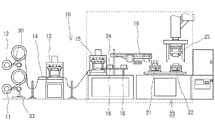
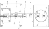
図1はコネクタ端子類の製造装置の一実施例の構成を示す説明図である。図2は図1のコネクタ端子類の製造装置の破線部で示した要部の構成を示す説明図である。図3は図1の製造工程毎のコネクタ端子類の構造を示す説明図である。 FIG. 1 is an explanatory view showing the configuration of an embodiment of a connector terminal manufacturing apparatus. FIG. 2 is an explanatory view showing a configuration of a main part indicated by a broken line part of the connector terminal manufacturing apparatus of FIG. FIG. 3 is an explanatory view showing the structure of connector terminals for each manufacturing process of FIG.
図1に示す通り、本実施例のコネクタ端子類の製造装置10は、捲回された黄銅製のキャリー帯材33が解かれながら搬出されるキャリー帯材ドラム11と、高価な金メッキされた帯状基板の片側に予め平行にコネクタ端子列が形成されたコネクタ端子帯30が解かれながら搬出されるコネクタ端子ドラム12とがフープ材製造手段13に搬入される。
As shown in FIG. 1, the connector
フープ材製造手段13では、端子切断手段14によってコネクタ端子帯30から所定の長さLで切断されたコネクタ端子31と、搬出されるキャリー帯材33とを連結する。詳しくは、図3に示す通り、長手方向に沿って均等間隔で穿設された位置決め孔を兼ねたパイロット孔32によってコネクタ端子帯30が連続して間欠搬送される。
In the hoop material manufacturing means 13, the
このコネクタ端子帯30の所定位置のコネクタ端子を短く切断し、コネクタ端子帯30を所定の長さLで切断して、埋設用のコネクタ端子31とする。一方、長手方向に沿って均等間隔で穿設されたパイロット孔35によって連続して間欠搬送されるキャリー帯材33には等間隔でコネクタ端子支持部34が形成されている。
A connector terminal at a predetermined position of the
この支持部34に切断されたコネクタ端子31が連結される。これらの連結はコネクタ端子31のパイロット孔を位置決め孔32として、支持部34に形成された小突起36と合わせ、合わされたキャリー帯材が間欠的にフープ材製造手段13に搬送され、このフープ材製造手段13の上下動するプレス手段で小突起36をかしめることで成される。
The
図1に示す通り、フープ材製造手段13によって切断されたコネクタ端子31が連結されたキャリー帯材33は、次工程の端子材製造手段15で2つのコネクタ端子31を搭載したインサート成形用端子材としてのキャリー帯材片37に切断される。詳しくは、パイロット孔35によって間欠搬送されるキャリー帯材33を、図2及び図3に示す通り、上下動するプレス手段で2つのコネクタ端子31を搭載したキャリー帯材片37に切断する。
As shown in FIG. 1, the
端子材製造手段15で切断されたキャリー帯材片37は移送装置(図示せず)で図示しない金型供給手段によって受け渡し位置16に順に供給される第1金型である下金型24内の所定の位置に配置される。所定の位置にキャリー帯材片37が配置された下金型24は受け渡し位置16から下金型移送位置18へスライド手段17でスライド移動される。
下金型移送位置18へ移動された下金型24は下金型移送手段19で射出成形手段23のターンテーブル20の待機位置21に更に移送される。ターンテーブル待機位置21に移送された下金型24は射出ステージ位置22に回転移動され、この射出ステージ位置22で上方に控えた第2金型である上金型25との型締め後に金型内部に金型の上下から樹脂が射出される。射出後、上金型25が上方に移動した際に、図3に示される通り、個々のインサート成形品38が形成されたキャリー帯材片37が図示しない取出手段で取り出される。
The
本実施例では、ターンテーブル20によって待機位置21と射出ステージ位置22の2箇所缶で下金具を回動移動する例を示したが、大きな径のターンテーブルとして、端子材製造手段15で切断されたキャリー帯材片37を下金型に配置する位置及びそれ以降の位置との間でターンテーブルが1/3回動又は1/4回動の間欠回動させることにより金型の循環移動を行ってもよい。
In the present embodiment, an example is shown in which the lower metal fitting is pivotally moved by the
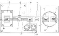
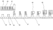
図4は別のコネクタ端子類の製造装置の構成を示す説明図である。図5は図4のコネクタ端子類の製造装置の破線部で示した要部の構成を示す説明図である。図6は図4の製造工程毎のコネクタ端子類の構造を示す説明図である。 FIG. 4 is an explanatory view showing the configuration of another connector terminal manufacturing apparatus. FIG. 5 is an explanatory view showing a configuration of a main part indicated by a broken line part of the manufacturing apparatus for connector terminals of FIG. FIG. 6 is an explanatory view showing the structure of connector terminals for each manufacturing process of FIG.
図5に示す通り、実施例1との相違は、第1金型である下金型54にキャリー帯材片67と共に他の副構成材69を射出ステージに至る前に下金型54内に配置することである。即ち、本実施例のコネクタ端子類の製造装置40は、捲回された黄銅製のキャリー帯材63が解かれながら搬出されるキャリー帯材ドラム41と、高価な金メッキされた帯状基板の片側に予め平行にコネクタ端子列が形成されたコネクタ端子帯60が解かれながら搬出されるコネクタ端子ドラム42とがフープ材製造手段43に搬入される。
As shown in FIG. 5, the difference from the first embodiment is that the
フープ材製造手段43では、端子切断手段44によってコネクタ端子帯60から所定の長さLで切断されたコネクタ端子61と、搬送されるキャリー帯材63とを連結する。詳しくは、図3に示す通り、長手方向に沿って均等間隔で穿設された位置決め孔を兼ねたパイロット孔62によってコネクタ端子帯60が連続して間欠搬送される。
In the hoop material manufacturing means 43, the
このコネクタ端子帯60の所定位置のコネクタ端子を短く切断し、コネクタ端子帯60を所定の長さLで切断して埋設用のコネクタ端子61とする。一方、長手方向に沿って均等間隔で穿設されたパイロット孔65によって連続して間欠搬送されるキャリー帯材63には等間隔でコネクタ端子支持部64が形成されている。
A connector terminal at a predetermined position of the
この支持部64に切断されたコネクタ端子61が連結される。これらの連結は、コネクタ端子61のパイロット孔を位置決め孔62として、支持部64に形成された小突起66と合わせ、合わされたキャリー帯材が間欠的にフープ材製造手段43に搬送され、このフープ材製造手段43の上下動するプレス手段で小突起66をかしめることで成される。
The
図4に示す通り、フープ材製造手段43によって切断されたコネクタ端子61が連結されたキャリー帯材63は、次工程の端子材製造手段45でキャリー帯材63を2つのコネクタ端子61を搭載したインサート成形用端子材としてのキャリー帯材片67に切断される。詳しくは、パイロット孔65によって間欠搬送されるキャリー帯材63を、図5及び図6に示す通り、上下動するプレス手段で2つのコネクタ端子61を搭載したキャリー帯材片67に切断する。
As shown in FIG. 4, the
端子材製造手段45で切断されたキャリー帯材片67は移送装置(図示せず)で図示しない金型供給手段によって受け渡し位置46に順に供給される下金型54内の所定の位置に配置される。所定の位置にキャリー帯材片67が配置された下金型54は受け渡し位置46から下金型移送位置48へスライド手段47でスライド移動される。
The
下金型移送位置48へ移動された下金型54は、下金型移送位置48に移動した下金型54の予め定められた位置に副構成材供給手段56によって副構成材69が配置される。副構成材69が配置された下金型54は、下金型移送手段49で射出成形手段53のターンテーブル50の待機位置51に更に移送される。
In the
ターンテーブル待機位置51に移送された下金型54は射出ステージ位置52に回転移動され、この射出ステージ位置52で上方に控えた第2金型である上金型55との型締め後に金型内部に樹脂が射出される。射出後、上金型55が上方に移動した際に、図6に示される通り、個々のインサート成形品68が形成されたキャリー帯材片67が図示しない取出手段で取り出される。
The
本実施例では、ターンテーブル50によって待機位置51と射出ステージ位置52の2箇所間で下金型を回動駆動する例を示したが、大きな径のターンテーブルとして、端子材製造手段45で切断されたキャリー帯材片67を下金型に配置する位置及びそれ以降の位置との間でターンテーブルが1/3回動又は1/4回動の間欠回動させることにより下金型の循環移動を行ってもよい。
In the present embodiment, an example in which the lower mold is rotationally driven between the
本発明によれば、高価な端子群であっても、コストを低減させて、効率よく生産することができるだけでなく、微細な端子群であっても効率よくインサート成形することが可能となる。 According to the present invention, even an expensive terminal group can be efficiently produced at a reduced cost, and even a minute terminal group can be efficiently insert-molded.
10、40…コネクタ端子類の製造装置、
11、41…キャリー帯材ドラム、
12、42…コネクタ端子ドラム、
13、43…フープ材製造手段、
14、44…端子切断手段、
15、45…端子材製造手段、
16、46…受け渡し位置、
17、47…スライド手段、
18、48…下金型移送位置、
19、49…下金型移送手段、
20、50…ターンテーブル、
21、51…ターンテーブル待機位置、
22、52…射出ステージ位置、
23、53…射出成形手段、
24、54…下金型、
25、55…上金型、
56…副構成材供給手段、
30、60…コネクタ端子帯、
31、61…コネクタ端子、
32、62…パイロット孔(位置決め孔)、
33、63…キャリー帯材、
34、64…コネクタ端子支持部、
35、65…パイロット孔、
36、66…小突起、
37、67…キャリー帯材片(インサート成形用端子材)、
38、68…インサート成形品、
69…副構成材、
10, 40 ... Manufacturing apparatus for connector terminals,
11, 41 ... Carry belt drum,
12, 42 ... Connector terminal drum,
13, 43 ... Hoop material manufacturing means,
14, 44 ... terminal cutting means,
15, 45 ... Terminal material manufacturing means,
16, 46 ... delivery position,
17, 47 ... slide means,
18, 48 ... Lower mold transfer position,
19, 49 ... Lower mold transfer means,
20, 50 ... turntable,
21, 51 ... turntable standby position,
22, 52 ... injection stage position,
23, 53 ... injection molding means,
24, 54 ... lower mold,
25, 55 ... Upper mold,
56 ... Sub-component supply means
30, 60 ... Connector terminal band,
31, 61 ... Connector terminals,
32, 62 ... pilot holes (positioning holes),
33, 63 ... carry belt,
34, 64 ... connector terminal support,
35, 65 ... pilot holes,
36, 66 ... small protrusions,
37, 67 ... Carry strip piece (terminal material for insert molding),
38, 68 ... insert molded product,
69 ... sub-components,
Claims (5)
前記第1金型及びこの第1金型に型締される第2金型は、2つ以上のインサート成形品の組が製造されるものであり、
前記埋設コネクタ端子は、キャリー帯材の長手方向に沿って所定間隔の離間位置に2つ以上結合されたインサート成形用端子材として、前記射出ステージ前の第1金型内又は第2金型内の所定位置に配置されることを特徴とするコネクタ端子類の製造法。 A plurality of first molds that circulate and move through a plurality of stages including an injection stage through which resin is injected, and a second mold that is clamped to the first mold together with embedded connector terminals that are sealed inside the injection stage. An insert molding method using a mold,
The first mold and the second mold clamped to the first mold are manufactured as a set of two or more insert molded products,
The embedded connector terminals are inserted into the first mold or the second mold before the injection stage, as two or more insert molding terminal members that are coupled at a predetermined distance apart along the longitudinal direction of the carry belt member. A method for manufacturing connector terminals, wherein the connector terminals are arranged at predetermined positions.
型締め結合された際に内部に形成される射出空間には、予め定められた間隔で2つ以上の埋設コネクタ端子を固定された予め定められた長さのインサート成形用端子材を保持する領域が備えられていることを特徴とするインサート成形用金型。 An insert molding die comprising a first die and a second die that are clamp-bonded to each other used in the production method according to any one of claims 1 to 3,
In the injection space formed inside when the molds are clamped and joined, a region for holding a predetermined length of insert molding terminal material to which two or more embedded connector terminals are fixed at a predetermined interval The mold for insert molding characterized by being provided with.
Priority Applications (1)
| Application Number | Priority Date | Filing Date | Title |
|---|---|---|---|
| JP2016083673A JP2017193083A (en) | 2016-04-19 | 2016-04-19 | Method of manufacturing connector terminal, and metal molding for insert molding used for the method |
Applications Claiming Priority (1)
| Application Number | Priority Date | Filing Date | Title |
|---|---|---|---|
| JP2016083673A JP2017193083A (en) | 2016-04-19 | 2016-04-19 | Method of manufacturing connector terminal, and metal molding for insert molding used for the method |
Publications (1)
| Publication Number | Publication Date |
|---|---|
| JP2017193083A true JP2017193083A (en) | 2017-10-26 |
Family
ID=60155208
Family Applications (1)
| Application Number | Title | Priority Date | Filing Date |
|---|---|---|---|
| JP2016083673A Pending JP2017193083A (en) | 2016-04-19 | 2016-04-19 | Method of manufacturing connector terminal, and metal molding for insert molding used for the method |
Country Status (1)
| Country | Link |
|---|---|
| JP (1) | JP2017193083A (en) |
Cited By (2)
| Publication number | Priority date | Publication date | Assignee | Title |
|---|---|---|---|---|
| CN108127867A (en) * | 2018-01-23 | 2018-06-08 | 东莞利铿电子有限公司 | Material belt type injection mold |
| JP7058899B1 (en) * | 2021-12-02 | 2022-04-25 | 旭計器株式会社 | Resin sealing method and resin sealing device for heat-responsive switches |
-
2016
- 2016-04-19 JP JP2016083673A patent/JP2017193083A/en active Pending
Cited By (2)
| Publication number | Priority date | Publication date | Assignee | Title |
|---|---|---|---|---|
| CN108127867A (en) * | 2018-01-23 | 2018-06-08 | 东莞利铿电子有限公司 | Material belt type injection mold |
| JP7058899B1 (en) * | 2021-12-02 | 2022-04-25 | 旭計器株式会社 | Resin sealing method and resin sealing device for heat-responsive switches |
Similar Documents
| Publication | Publication Date | Title |
|---|---|---|
| CN105406241B (en) | Making method for electric connector | |
| CN110326100B (en) | Method for inserting wiring into trench of semiconductor chip and apparatus for implementing the method | |
| MY146673A (en) | Electrical connector and manufacturing method thereof | |
| JP2017193083A (en) | Method of manufacturing connector terminal, and metal molding for insert molding used for the method | |
| CN109088295B (en) | 4PIN connector manufacturing process | |
| US10319519B2 (en) | Method for producing an induction component | |
| MY151781A (en) | Method and process for manufacturing a terminal block | |
| CN108134227A (en) | Positive and negative socket, connector and its manufacturing method | |
| CN108173020A (en) | Positive and negative socket, connector and its manufacturing method | |
| CN203558652U (en) | Splicing tape reel and tape | |
| CN105846234B (en) | Card pallet for electronic equipment and the tray bearing component for using card pallet | |
| US7837920B2 (en) | Forming method using pressing and injection-molding multifunction die, forming apparatus provided with pressing and injection-molding multifunction die, and metal-resin molded product formed by the method or the apparatus | |
| KR102077162B1 (en) | Injection apparatus for manufacturing a connector | |
| KR101400458B1 (en) | Choke coil manufacturing apparatus | |
| US9131636B2 (en) | Method of manufacturing electrical circuit traces | |
| TWI496960B (en) | Verfahren zur herstellung von metallisierungen auf kunststoffteilen | |
| WO2016092821A1 (en) | Method for manufacturing card connector, and die for same | |
| EP0292370A2 (en) | Packaging technique for batteries | |
| JP2007083468A (en) | Structure of mold for insert molding | |
| KR100953060B1 (en) | Carrier tape forming machine | |
| TW200636959A (en) | Method of making reinforced semiconductor package | |
| JP2013197678A (en) | Multi-band antenna and manufacturing method thereof | |
| KR101026539B1 (en) | Connector and manufacturing method of the connector | |
| US8920906B2 (en) | Molded pull-off tab | |
| CN105632752A (en) | Air core coil fitting apparatus |