JP2017193073A - Manufacturing method of liquid discharge head - Google Patents
Manufacturing method of liquid discharge head Download PDFInfo
- Publication number
- JP2017193073A JP2017193073A JP2016083249A JP2016083249A JP2017193073A JP 2017193073 A JP2017193073 A JP 2017193073A JP 2016083249 A JP2016083249 A JP 2016083249A JP 2016083249 A JP2016083249 A JP 2016083249A JP 2017193073 A JP2017193073 A JP 2017193073A
- Authority
- JP
- Japan
- Prior art keywords
- liquid
- material layer
- repellent material
- group
- liquid repellent
- Prior art date
- Legal status (The legal status is an assumption and is not a legal conclusion. Google has not performed a legal analysis and makes no representation as to the accuracy of the status listed.)
- Pending
Links
Images

Landscapes
- Particle Formation And Scattering Control In Inkjet Printers (AREA)
- Materials Applied To Surfaces To Minimize Adherence Of Mist Or Water (AREA)
Abstract
Description
本発明は、液体吐出ヘッドの製造方法に関するものである。 The present invention relates to a method for manufacturing a liquid discharge head.
インクジェットプリンタに代表される液体吐出装置は、液体吐出ヘッドを有している。液体吐出ヘッドは、基板に設けられたエネルギー発生素子によって液体にエネルギーを与えることで、吐出口から液体を吐出し、記録媒体上に画像や文字を記録する。 A liquid discharge apparatus represented by an ink jet printer has a liquid discharge head. The liquid discharge head discharges liquid from the discharge port by applying energy to the liquid by an energy generating element provided on the substrate, and records images and characters on a recording medium.
特許文献1には、基体上にインク流路パターンを形成し、この上にインク流路壁となる被覆樹脂層を形成し、被覆樹脂層に吐出口を形成する、液体吐出ヘッドの製造方法が記載されている。特許文献1では、フォトリソグラフィーの手法によってインク流路パターンや吐出口を形成している。 Patent Document 1 discloses a method for manufacturing a liquid discharge head, in which an ink flow path pattern is formed on a substrate, a coating resin layer serving as an ink flow path wall is formed thereon, and discharge ports are formed in the coating resin layer. Have been described. In Patent Document 1, an ink flow path pattern and ejection openings are formed by a photolithography technique.
一方、液体吐出ヘッドには、吐出特性の安定化のため、吐出口が開口する吐出口面に撥液層を設けることがある。特許文献2には、フッ素含有基を有する加水分解性シラン化合物とカチオン重合性基を有する加水分解性シラン化合物との縮合物によって、吐出口面に撥液層を形成することが記載されている。
On the other hand, a liquid discharge head may be provided with a liquid repellent layer on the discharge port surface where the discharge port opens in order to stabilize discharge characteristics.
ところで、このような液体吐出ヘッドにおいて、吐出口面を所望の形状とすることができれば、液体の吐出を制御できる。例えば、吐出口面を平坦にすると、液体の吐出が安定化し、より高精度な画像や文字が記録できる。吐出口面が高い平坦性を有していることにより、基板から吐出口面までの距離や、吐出口の形状が安定化し、吐出する液体の体積が一定に近くなるためである
吐出口面を平坦化するには、吐出口面を押圧する方法が考えられる。特許文献3には、層の表面を平坦化するために、平坦表面を有する物体で層を押圧する方法が記載されている。この方法を液体吐出ヘッドの吐出口面に適用する場合、液体吐出ヘッドの吐出口面に対して平坦表面を有する物体を押圧することで、吐出口面を平坦化することになる。
By the way, in such a liquid discharge head, the discharge of the liquid can be controlled if the discharge port surface can have a desired shape. For example, when the discharge port surface is flattened, liquid discharge is stabilized, and more accurate images and characters can be recorded. This is because the discharge port surface has high flatness, so that the distance from the substrate to the discharge port surface and the shape of the discharge port are stabilized, and the volume of the liquid to be discharged becomes nearly constant. To flatten the surface, a method of pressing the discharge port surface can be considered.
特許文献3に記載されている方法を用いて、平坦表面を有する物体(以下、型とする)にて吐出口面を押圧する場合、吐出口面と型との間の離型性を高くする必要がある。これらの間の離型性が低いと、吐出口面から型を剥離した際に、吐出口面の形状が変形してしまうことがある。そこで、型の表面にフッ素等を有する離型材を塗布し、離型層を形成した型によって吐出口面を押圧することが考えられる。
When the discharge port surface is pressed by an object having a flat surface (hereinafter referred to as a mold) using the method described in
しかしながら、本発明者らの検討によれば、型の表面に離型層を形成した場合であっても、転写及び剥離を繰り返してその回数が多くなっていくと、吐出口面が変形してしまうという課題を見出した。これは、剥離の際に吐出口面を形成する部材が型に付着し、その型を用いて転写を行うことで発生するものと考えられる。 However, according to the study by the present inventors, even when a release layer is formed on the surface of the mold, if the number of times of repeated transfer and peeling increases, the discharge port surface is deformed. I found the problem of end. This is considered to occur when a member that forms the discharge port surface adheres to the mold at the time of peeling, and transfer is performed using the mold.
また、逆に離型材が吐出口面に付着してしまうことによって、吐出口面の物性が変化してしまうことがあることも分かった。特許文献2に記載されているように、吐出口面には撥液層が形成されていることがある。従って、離型材が吐出口面に付着してしまうと、吐出口面の物性(撥液性)がばらつき、液体の吐出に影響を与えることもある。
It has also been found that the physical properties of the discharge port surface may change due to the release material adhering to the discharge port surface. As described in
従って、本発明は、離型材を有する型によって吐出口面を押圧し、吐出口面から型を離型した場合であっても、吐出口面の形状や物性が予期せぬものになってしまうことを抑制することを目的とする。 Therefore, in the present invention, even when the discharge port surface is pressed by a mold having a release material and the mold is released from the discharge port surface, the shape and physical properties of the discharge port surface become unexpected. It aims at suppressing this.
本発明は、基板と、流路の壁である流路壁と撥液層とを有し吐出口面に吐出口が開口する部材と、を有する液体吐出ヘッドの製造方法であって、前記流路壁となる樹脂層と、前記樹脂層上に前記撥液層となる撥液材料層と、を有する基板を用意する工程と、前記吐出口面となる前記撥液材料層の表面を、土台部分と表面部分とを有する型の前記表面部分で押圧し、前記撥液材料層の表面に前記表面部分の形状を転写する転写工程と、前記撥液材料層の表面から前記型を剥離する剥離工程と、前記樹脂層及び前記撥液材料層に、前記吐出口を形成する工程と、を有し、前記撥液材料層及び前記表面部分は、いずれもフッ素を有するシロキサン化合物を含有することを特徴とする液体吐出ヘッドの製造方法である。 The present invention is a method for manufacturing a liquid discharge head, comprising: a substrate; a flow path wall that is a flow path wall; and a liquid repellent layer; A step of preparing a substrate having a resin layer serving as a road wall and a liquid repellent material layer serving as the liquid repellent layer on the resin layer; and a surface of the liquid repellent material layer serving as the discharge port surface. A transfer step of pressing the surface portion of the mold having a portion and a surface portion to transfer the shape of the surface portion to the surface of the liquid repellent material layer, and peeling for peeling the mold from the surface of the liquid repellent material layer And a step of forming the discharge port in the resin layer and the liquid repellent material layer, and the liquid repellent material layer and the surface portion both contain a siloxane compound having fluorine. This is a feature of a method for manufacturing a liquid discharge head.
本発明によれば、離型材を有する型によって吐出口面を押圧し、吐出口面から型を離型した場合であっても、吐出口面の形状や物性が予期せぬものになってしまうことを抑制することができる。 According to the present invention, even when the discharge port surface is pressed by a mold having a release material and the mold is released from the discharge port surface, the shape and physical properties of the discharge port surface become unexpected. This can be suppressed.
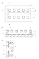
本発明で製造する液体吐出ヘッドの一例を、図1に示す。 An example of the liquid discharge head manufactured by the present invention is shown in FIG.
図1(a)は、液体吐出ヘッドを上方から見た図である。図1(a)に示すように、吐出口面1には吐出口2が開口している。吐出口2は、配列方向に沿って2列で並んでいる。図1において点線で示しているのは、吐出口面1よりも奥側にある部分である。吐出口2の下方にはエネルギー発生素子3があり、エネルギー発生素子3も吐出口2に対応して2列で配列している。エネルギー発生素子3としては、発熱抵抗体や圧電体が挙げられる。2列のエネルギー発生素子3の間には、供給口4が開口している。供給口4は、流路5に液体を供給する。
FIG. 1A is a view of the liquid discharge head as viewed from above. As shown in FIG. 1A, a
図1(b)は、図1(a)に示す液体吐出ヘッドのA−A´における断面図である。エネルギー発生素子3は、基板8上に設けられている。基板8はシリコン等で形成されており、基板上にはエネルギー発生素子3と、エネルギー発生素子3を内包する流路5とが設けられている。流路5は、流路の壁である流路壁6によって形成されている。流路壁6上には、撥液性を有する撥液層7が設けられている。流路壁6及び撥液層7のうち、エネルギー発生素子3上の領域は開口している。この開口している部分が吐出口2である。ここでは流路壁6と撥液層7とを分けて図示しているが、両者は一体となっていてもよいし、両者の間に明確な境界が存在しなくてもよい。流路壁6と撥液層7と合わせて「部材」と呼ぶ。この部材は、流路5及び吐出口2を形成している。部材のうち、吐出口が開口している外側(基板8から遠い側)の面が吐出口面1である。
FIG. 1B is a cross-sectional view taken along the line AA ′ of the liquid discharge head shown in FIG. The energy generating
図1(c)は、図1(a)に示す液体吐出ヘッドのB−B´における断面図である。基板8には、供給口4が開口している。供給口4は、2つのエネルギー発生素子3の間に開口しており、流路5へと液体を供給する。流路5に供給された液体は、エネルギー発生素子3によってエネルギーを与えられ、吐出口2から吐出される。吐出後、紙等の記録媒体に着弾し、画像や文字の記録が行われる。
FIG. 1C is a cross-sectional view taken along the line BB ′ of the liquid discharge head shown in FIG. A
次に、本発明の液体吐出ヘッドの製造方法を、図2を用いて説明する。図2は、図1(b)と同様の位置における液体吐出ヘッドの断面図である。 Next, the manufacturing method of the liquid discharge head of the present invention will be described with reference to FIG. FIG. 2 is a cross-sectional view of the liquid ejection head at the same position as in FIG.
まず、図2(a)に示すように、表面上にエネルギー発生素子3を有する基板8を用意する。基板8上には、流路型9も形成されている。流路型9は、後で除去されることで流路となるものであり、流路の形状にパターニングされたものである。流路型9は感光性樹脂で形成することが好ましく、特にポジ型感光性樹脂で形成することが好ましい。
First, as shown in FIG. 2A, a
次に、図2(b)に示すように、流路型9を覆うように、樹脂層10を形成する。樹脂層10は、後で図1に示す流路壁6となるものである。樹脂層10は、感光性樹脂で形成することが好ましく、特にネガ型感光性樹脂で形成することが好ましい。より具体的には、カチオン重合性基としてエポキシ基およびオキセタン基、ビニルエーテル基等によって表される環状エーテル基等を有する樹脂であることが好ましい。中でも、入手の容易さおよび反応制御の観点で、エポキシ基を有する樹脂であることが好ましい。樹脂層10の厚みは、5.0μm以上15.0μm以下とすることが好ましい。
Next, as illustrated in FIG. 2B, a
樹脂層10上には、撥液材料層11が設けられている。樹脂層上の撥液材料層11は、後で図1に示す撥液層7となるものであり、フッ素を有するシロキサン化合物を含有している。撥液材料層11の厚みは、0.1μm以上3.0μm以下とすることが好ましい。
A liquid
さらに、図2(b)に示すように、樹脂層10及び撥液材料層11を設けた基板上に、型12を配置する。型12は、土台部分13と、表面部分14とで構成されている。土台部分13は、シリコン、石英、硝子、ゴム等の少なくともいずれかで形成することができる。特に、表面に水酸基が多数存在する材料で形成することが好ましく、加工性等の点も併せると石英や硝子で形成することが好ましい。他にも、加熱時間短縮や均温性向上のため型の熱伝導性を増したい場合や、帯電対策で導電性を増したい場合などには、金属の母材の表面に石英を蒸着成膜したものを用いることが好ましい。表面部分14は、従来、離型材が塗布されて構成されていた部分である。
Further, as shown in FIG. 2B, a
次に、図2(c)に示すように、撥液材料層11の表面を、型12の表面部分14で押圧し、型12の表面形状を撥液材料層11の表面に転写する(転写工程)。型12の表面形状は平坦形状である。この転写工程は、撥液材料層11の流動性向上のために加熱下で行うことが好ましい。また、気泡の混入を抑制する為に真空下で行うことが好ましい。撥液材料層11の表面は、図1に示すように後で吐出口2が開口する吐出口面1となる。即ち、撥液材料層11の表面を吐出口面とよぶこともできる。
Next, as shown in FIG. 2 (c), the surface of the liquid
続いて、型12を上昇させて、撥液材料層11の表面から型12を剥離する(剥離工程)。型12を剥離した後の状態を、図2(d)に示す。型12の表面部分の形状が平坦形状であると、撥液材料層11の表面も平坦になる。
Subsequently, the
次に、図2(e)に示すように、流路型9を除去して流路5を形成する。また、樹脂層10及び撥液材料層11に、吐出口2を形成し、流路壁6と撥液層7とを形成する。吐出口2は、例えばフォトリソグラフィーによって形成する。樹脂層10及び撥液材料層11は、硬化させることで流路壁6及び撥液層7となる。撥液層7の表面は吐出口2が開口する吐出口面1である。
Next, as shown in FIG. 2 (e), the
最後に、必要に応じて基板8に供給口を設けたり、基板8を切断して複数の基板分離したり、エネルギー発生素子3に電気接続を行ったりすることで、液体吐出ヘッドの製造が完成する。
Finally, if necessary, the
ここで、上述の通り、型12の表面部分14を、一般的な離型材によって形成した離型層とした場合、同じ型12を用いて複数の基板に対して転写、剥離を繰り返すと、吐出口面1の形状や物性が予期せぬものになってしまう場合がある。一般的な離型材としては、例えばオプツールDSX(商品名、ダイキン工業製)やサイトップ(商品名、旭硝子製)が挙げられる。
Here, as described above, when the
これに対して、本発明では、型12の表面部分14がフッ素を有するシロキサン化合物を含有している。即ち、表面部分14と、表面部分14が接触する撥液材料層11とは、いずれもフッ素を有するシロキサン化合物を含有している。このように、撥液材料層11及び表面部分14がいずれもフッ素を有するシロキサン化合物を含有していることで、吐出口面1の形状や物性が予期せぬものとなることが抑制される。本発明者らは、このような効果が発現する理由を、材料分析等の検討結果から以下のようなものと推測している。まず、表面部分14に撥液材料層11と同様にフッ素を有するシロキサン化合物を含有させると、型12の表面部分14を撥液材料層11の表面(吐出口面)から剥離した際に、表面部分14の一部が撥液材料層11の表面に付着する。そしてこれと同時に、撥液材料層11の一部も表面部分14に付着する。表面部分14は、撥液材料層11と同じくフッ素を有するシロキサン化合物を含有している。従って、転写工程を繰り返すと、転写工程において表面部分14にかかる熱等により、表面部分14に付着した撥液材料層11が表面部分14と化学的に結合しやすくなる。この結合によって、表面部分14に安定な平衡状態が形成される。また、撥液材料層11及び表面部分14がいずれもフッ素を有するシロキサン化合物を含有していることから、物性の変化も発現しにくい。従って、転写工程を繰り返しても、表面部分14が安定した状態となり、吐出口面1となる撥液材料層11の表面においても、形状や物性が安定した状態となる。
On the other hand, in the present invention, the
上述の通り、撥液材料層11は、フッ素を有するシロキサン化合物を含有している。フッ素を有するシロキサン化合物としては、シラン化合物の縮合物が挙げられる。より具体的には、フッ素原子を有する基を有する加水分解性シラン化合物と、エポキシ基またはオキセタン基を有する加水分解性シラン化合物と、アルキル基またはアリール基を有する加水分解性シラン化合物との縮合物である。
As described above, the liquid
フッ素原子を有する基を有する加水分解性シラン化合物としては、下記の式(1)で示されるシラン化合物が好適に用いられる。 As the hydrolyzable silane compound having a group having a fluorine atom, a silane compound represented by the following formula (1) is preferably used.
式(1)
Rf−Si(R)bX(3−b)
(Rfは炭素原子に結合する1個から30個のフッ素原子を有する非加水分解性の置換基、Rは非加水分解性の置換基、Xは加水分解性の置換基、bは0から2の整数である。)
式(1)で示されるシラン化合物としては、例えば以下の式(1−a)、(1−b)、(1−c)、及び(1−d)で示されるシラン化合物が挙げられる。
Formula (1)
R f -Si (R) b X (3-b)
(R f is a non-hydrolyzable substituent having 1 to 30 fluorine atoms bonded to a carbon atom, R is a non-hydrolyzable substituent, X is a hydrolyzable substituent, b is 0 to 0 (It is an integer of 2.)
Examples of the silane compound represented by the formula (1) include silane compounds represented by the following formulas (1-a), (1-b), (1-c), and (1-d).
式(1−a)
F−Rp−A−SiXaY3−a
式(1−b)
R3−aXaSi−A−Rp−A−SiXaY3−a
Formula (1-a)
F-R p -A-SiX a Y 3-a
Formula (1-b)
R 3-a X a Si- A-R p -A-SiX a Y 3-a

上記式(1−a)、(1−b)、(1−c)、及び(1−d)中、Rpはパーフルオロポリエーテル基である。また、Aは炭素数1から12の有機基、Xは加水分解性の置換基、Yは非加水分解性の置換基、Zは水素原子又はアルキル基、Rは非加水分解性の置換基、Qは2価又は3価の結合基である。Qが2価のときn=1、Qが3価のときn=2である。aは1から3の整数、mは1から4の整数である。 In the above formulas (1-a), (1-b), (1-c), and (1-d), R p is a perfluoropolyether group. A is an organic group having 1 to 12 carbon atoms, X is a hydrolyzable substituent, Y is a non-hydrolyzable substituent, Z is a hydrogen atom or an alkyl group, R is a non-hydrolyzable substituent, Q is a divalent or trivalent linking group. When Q is divalent, n = 1, and when Q is trivalent, n = 2. a is an integer of 1 to 3, and m is an integer of 1 to 4.
上記式(1−a)、(1−b)、(1−c)、及び(1−d)中のXとしては、例えばハロゲン原子、アルコキシ基、アミノ基、水素原子等が挙げられる。その中でも、加水分解反応により脱離した基がカチオン重合反応を阻害せず、反応性を制御しやすいという観点から、メトキシ基、エトキシ基、プロポキシ基等のアルコキシ基が好ましい。Yとしては、メチル基、エチル基、プロピル基、フェニル基等が挙げられる。Zのアルキル基としては、メチル基、エチル基、プロピル基等が挙げられる。Rとしては、炭素数1から20のアルキル基、フェニル基等が挙げられる。Qとしては、炭素原子、窒素原子等が挙げられる。Aの炭素数1から12の有機基としては、メチル基、エチル基、プロピル基等のアルキル基等が挙げられる。また置換基を有するアルキル基も用いられる。 Examples of X in the above formulas (1-a), (1-b), (1-c), and (1-d) include a halogen atom, an alkoxy group, an amino group, and a hydrogen atom. Among them, an alkoxy group such as a methoxy group, an ethoxy group, and a propoxy group is preferable from the viewpoint that the group eliminated by the hydrolysis reaction does not inhibit the cationic polymerization reaction and the reactivity is easily controlled. Examples of Y include a methyl group, an ethyl group, a propyl group, and a phenyl group. Examples of the alkyl group for Z include a methyl group, an ethyl group, and a propyl group. Examples of R include an alkyl group having 1 to 20 carbon atoms and a phenyl group. Examples of Q include a carbon atom and a nitrogen atom. Examples of the organic group having 1 to 12 carbon atoms of A include alkyl groups such as a methyl group, an ethyl group, and a propyl group. An alkyl group having a substituent is also used.
上記式(1−a)、(1−b)、(1−c)、及び(1−d)において、Rp内の繰り返し単位数は1から30の整数であることが好ましい。なお、Rp内の繰り返し単位数とは、Rpに含まれるパーフルオロポリエーテル基の繰り返し単位の数を示す。パーフルオロポリエーテル基であるRpは下記式(1−e)で表される基であることが好ましい。 In the above formulas (1-a), (1-b), (1-c), and (1-d), the number of repeating units in R p is preferably an integer of 1 to 30. Note that the number of repeating units in the R p, represents the number of repeating units of the perfluoropolyether group contained in R p. R p which is a perfluoropolyether group is preferably a group represented by the following formula (1-e).
上記式(1−e)中、o、p、q及びrはそれぞれ0又は1以上の整数であり、o、p、q及びrの少なくとも一つは1以上の整数である。o、p、q又はrは、1から30の整数であることが好ましい。式(1−e)中のo、p、q又はrが、前述の繰り返し単位数に相当する。 In the above formula (1-e), o, p, q and r are each 0 or an integer of 1 or more, and at least one of o, p, q and r is an integer of 1 or more. o, p, q or r is preferably an integer of 1 to 30. In the formula (1-e), o, p, q, or r corresponds to the number of repeating units described above.
上記式(1−a)、(1−b)、(1−c)、及び(1−d)中のパーフルオロポリエーテル基であるRpの平均分子量は、500〜5000であることが好ましく、500〜2000であることがより好ましい。Rpの平均分子量が500以上であることにより、十分な撥水性が得られる。また、Rpの平均分子量が5000以下であることにより、十分な溶媒への溶解性が得られる。パーフルオロポリエーテル基は、その特性上、繰り返し単位数(式(1−e)中のo、p、q、r等)の異なるものの混合物であるが、パーフルオロポリエーテル基の平均分子量とは式(1−e)の繰り返し単位で示される部分の総和の分子量の平均を示す。 The average molecular weight of R p that is a perfluoropolyether group in the above formulas (1-a), (1-b), (1-c), and (1-d) is preferably 500 to 5,000. 500 to 2000 is more preferable. By average molecular weight of R p of 500 or more, sufficient water repellency can be obtained. Further, the average molecular weight of R p of 5,000 or less, solubility in sufficient solvent is obtained. The perfluoropolyether group is a mixture of different numbers of repeating units (o, p, q, r, etc. in the formula (1-e)) due to its characteristics. What is the average molecular weight of the perfluoropolyether group? The average of the molecular weight of the sum total of the part shown by the repeating unit of Formula (1-e) is shown.
エポキシ基またはオキセタン基を有する加水分解性シラン化合物としては、下記の式(2)で示されるシラン化合物が好適に用いられる。 As the hydrolyzable silane compound having an epoxy group or an oxetane group, a silane compound represented by the following formula (2) is preferably used.
式(2)
Rc−Si(R)bX(3−b)
(Rcはカチオン重合性基を有する非加水分解性の置換基、Rは非加水分解性の置換基、Xは加水分解性の置換基、bは0から2の整数である。)
式(2)で示されるシラン化合物としては、特に限定されないが、下記式(2−a)で表される化合物であることが好ましい。
Formula (2)
R c -Si (R) b X (3-b)
( Rc is a non-hydrolyzable substituent having a cationic polymerizable group, R is a non-hydrolyzable substituent, X is a hydrolyzable substituent, and b is an integer of 0 to 2.)
Although it does not specifically limit as a silane compound shown by Formula (2), It is preferable that it is a compound represented by following formula (2-a).
式(2−a)
RC−Si(R)bX(3−b)
上記式(2−a)中、RCはエポキシ基を有する非加水分解性の置換基、Rは非加水分解性の置換基、Xは加水分解性の置換基を示す。bは0から2の整数である。bは0または1であることが好ましく、0であることがより好ましい。
Formula (2-a)
R C —Si (R) b X (3-b)
In the above formula (2-a), R C represents a non-hydrolyzable substituent having an epoxy group, R represents a non-hydrolyzable substituent, and X represents a hydrolyzable substituent. b is an integer of 0 to 2. b is preferably 0 or 1, and more preferably 0.
上記式(2−a)中、RCは1つ以上のエポキシ基を有する有機基である。RCの具体例としては、グリシドキシプロピル基、エポキシシクロヘキシルエチル基等が挙げられる。非加水分解性の置換基Rとしては、メチル基、エチル基などのアルキル基、フェニル基などが挙げられる。加水分解性の置換基Xとしては、ハロゲン原子、アルコキシ基、アミノ基、水素原子等が挙げられる。その中でも、加水分解反応により脱離した基がカチオン重合反応を阻害せず、反応性を制御しやすいという観点から、メトキシ基、エトキシ基、プロポキシ基等のアルコキシ基が好ましい。また、加水分解性基の一部が加水分解によって水酸基となったりシロキサン結合を形成したりしているものを用いても良い。式(2−a)で表されるエポキシ基を有する加水分解性シラン化合物であって、Xがアルコキシ基の場合の例として具体的には以下のものが挙げられる。グリシドキシプロピルトリメトキシシラン、グリシドキシプロピルトリエトキシシラン、エポキシシクロヘキシルエチルトリメトキシシラン、エポキシシクロヘキシルエチルトリエトキシシラン。グリシドキシプロピルメチルジメトキシシラン、グリシドキシプロピルメチルジエトキシシラン。グリシドキシプロピルジメチルメトキシシラン、グリシドキシプロピルジメチルエトキシシラン等が挙げられる。これらのエポキシ基を有する加水分解性シラン化合物は、一種のみを用いてもよく、二種以上を併用してもよい。 In the above formula (2-a), R C is an organic group having one or more epoxy groups. Specific examples of RC include glycidoxypropyl group, epoxycyclohexylethyl group and the like. Examples of the non-hydrolyzable substituent R include alkyl groups such as a methyl group and an ethyl group, and a phenyl group. Examples of the hydrolyzable substituent X include a halogen atom, an alkoxy group, an amino group, and a hydrogen atom. Among them, an alkoxy group such as a methoxy group, an ethoxy group, and a propoxy group is preferable from the viewpoint that the group eliminated by the hydrolysis reaction does not inhibit the cationic polymerization reaction and the reactivity is easily controlled. Moreover, you may use what a part of hydrolyzable group turns into a hydroxyl group or forms a siloxane bond by hydrolysis. Specific examples of the hydrolyzable silane compound having an epoxy group represented by the formula (2-a), wherein X is an alkoxy group, include the following. Glycidoxypropyltrimethoxysilane, glycidoxypropyltriethoxysilane, epoxycyclohexylethyltrimethoxysilane, epoxycyclohexylethyltriethoxysilane. Glycidoxypropylmethyldimethoxysilane, glycidoxypropylmethyldiethoxysilane. Examples thereof include glycidoxypropyldimethylmethoxysilane and glycidoxypropyldimethylethoxysilane. These hydrolyzable silane compounds having an epoxy group may be used alone or in combination of two or more.
アルキル基またはアリール基を有する加水分解性シラン化合物としては、下記の式(3)で示されるシラン化合物が好適に用いられる。 As the hydrolyzable silane compound having an alkyl group or an aryl group, a silane compound represented by the following formula (3) is preferably used.
式(3)
Ra−SiX(4−a)
(Raは置換または非置換アルキル基および置換または非置換アリール基から選ばれる非加水分解性の置換基、Xは加水分解性の置換基、aは0から3の整数である。)
式(3)で示されるシラン化合物としては、特に限定されないが、下記式(3−a)で表される化合物であることが好ましい。
Formula (3)
R a -SiX (4-a)
(R a is a nonhydrolyzable substituent selected from a substituted or unsubstituted alkyl group and a substituted or unsubstituted aryl group, X is a hydrolyzable substituent, and a is an integer of 0 to 3.)
Although it does not specifically limit as a silane compound shown by Formula (3), It is preferable that it is a compound represented by following formula (3-a).
式(3−a)
(Rd)a−SiX(4−a)
上記式(3−a)中、Rdはアルキル基または芳香族基、Xは式(2−a)と同様の加水分解性の置換基である。aは1から3の整数である。Rdとしては、メチル基、エチル基、プロピル基、ブチル基、ヘキシル基、フェニル基等が挙げられる。式(3−a)で表される加水分解性シラン化合物としては、具体的には以下のものが挙げられる。メチルトリメトキシシラン、メチルトリエトキシシラン、メチルトリプロポキシシラン、エチルトリメトキシシラン。エチルトリエトキシシラン、エチルトリプロポキシシラン、プロピルトリメトキシシラン、プロピルトリエトキシシラン、プロピルトリプロポキシシラン。ジメチルジメトキシシラン、ジメチルジエトキシシラン、フェニルトリメトキシシラン、フェニルトリエトキシシラン等が挙げられる。これらの式(3−a)で表される加水分解性シラン化合物は、一種のみを用いてもよく、二種以上を併用してもよい。
Formula (3-a)
(R d ) a -SiX (4-a)
In the formula (3-a), R d is an alkyl group or an aromatic group, and X is a hydrolyzable substituent similar to that in the formula (2-a). a is an integer of 1 to 3. Examples of R d include a methyl group, an ethyl group, a propyl group, a butyl group, a hexyl group, and a phenyl group. Specific examples of the hydrolyzable silane compound represented by the formula (3-a) include the following. Methyltrimethoxysilane, methyltriethoxysilane, methyltripropoxysilane, ethyltrimethoxysilane. Ethyltriethoxysilane, ethyltripropoxysilane, propyltrimethoxysilane, propyltriethoxysilane, propyltripropoxysilane. Examples thereof include dimethyldimethoxysilane, dimethyldiethoxysilane, phenyltrimethoxysilane, and phenyltriethoxysilane. These hydrolyzable silane compounds represented by the formula (3-a) may be used alone or in combination of two or more.
上記式(3−a)で表される加水分解性シラン化合物の存在により、縮合物の極性や架橋密度の制御が可能となる。また非反応性のRdを導入することで縮合物中の置換基の自由度が向上する。このため、パーフルオロポリエーテル基の空気界面側への配向、エポキシ基の配向が促進される。また、アルキル基の存在により、シロキサン結合の開裂が抑制され、撥液性、耐久性が向上する。 Due to the presence of the hydrolyzable silane compound represented by the above formula (3-a), the polarity of the condensate and the crosslinking density can be controlled. Moreover, the degree of freedom of substituents in the condensate is improved by introducing non-reactive R d . For this reason, the orientation of the perfluoropolyether group toward the air interface side and the orientation of the epoxy group are promoted. In addition, the presence of the alkyl group suppresses cleavage of the siloxane bond, and improves liquid repellency and durability.
他にも、フェニル基を有する加水分解性シラン化合物を用いて、縮合物を形成してもよい。 In addition, a condensate may be formed using a hydrolyzable silane compound having a phenyl group.
また、これらの撥液成分に加えて、撥液材料層11は、エポキシ樹脂や、光酸発生剤を含有していてもよい。エポキシ樹脂を含有する場合、フッ素を有するシロキサン化合物1質量部に対して、エポキシ樹脂を2質量部以上10質量部以下とすることが好ましい。また、光酸発生剤を含有する場合、フッ素を有するシロキサン化合物1質量部に対して、光酸発生剤は0.01質量部以上0.3質量部以下とすることが好ましい。
In addition to these liquid repellent components, the liquid
表面部分14の形成において、表面の平坦性に重きを置く場合には、撥液材料層11を硬化させる際の加熱処理と同様の条件で、表面部分14を加熱処理して硬化させることが好ましい。これは、撥液材料層11の加熱条件が、撥液材料層11の表面の面粗さをなるべく小さくするように定められていることによるものである。従って、撥液材料層11の加熱条件と同様にすることで、表面部分14の平坦性も高くなる。同様の条件で加熱処理するとは、撥液材料層11を硬化させる際の加熱温度をX℃としたとき、表面部分14の加熱温度をX±10℃とすることである。また、撥液材料層11を硬化させる際の加熱時間をY分としたとき、表面部分14の加熱時間をY±10分とすることである。尚、撥液材料層11及び表面部分14を硬化させる加熱とは、これらを形成する為の塗布液を塗布した後、最初に行う加熱のことを意味する。また、平坦性を高める上では、表面部分14に加熱処理をした後に有機溶剤で洗浄して余剰な材料を取り除くことが好ましい。
When emphasizing the flatness of the surface in the formation of the
表面部分14の形成において、耐久性や初期形状の安定性に重きを置く場合には、撥液材料層11を硬化させる際の加熱処理の条件と比較して、加熱温度を高くする、または加熱時間を長くすることが好ましい。撥液材料層11を硬化させる際の加熱温度をX℃としたとき、表面部分14の加熱温度をX+50℃以上とする。また、撥液材料層11を硬化させる際の加熱時間をY分としたとき、表面部分14の加熱時間をY+100分以上とする。上述のように同様の条件とする場合と比較すると、吐出口面の平坦性は若干低下するものの、加熱によりカチオン重合性基同士を重合させ、初期状態から強固な膜を形成することができる。また、強固な膜を得るためには、加熱に加えて光照射を行うことも好ましい。
In the formation of the
表面部分14の形成において、さらに膜を強固なものにする場合には、撥液材料層11として、シロキサン化合物の前駆体を土台部分13に塗布してもよい。例えば、フッ素原子を有する基を有する加水分解性シラン化合物と、エポキシ基またオキセタン基を有する加水分解性シラン化合物と、アルキル基またはアリール基を有する加水分解性シラン化合物とを、縮合させずにそのまま塗布する。シロキサン化合物を生成するための縮合反応に用いられるシラノール基を、土台部分13とのシランカップリング反応による結合に用いると、その分だけ化学結合の本数が増える。よって、土台部分13と表面部分14との密着性をより高めることができる。この方法によれば、理論的には単分子膜での成膜が可能となるため、平坦性を高める点でも好ましい。
In the formation of the
また、土台部分13にシロキサン化合物の前駆体を塗布する場合には、その混合比を、縮合反応にてシロキサン化合物を合成する場合と変えることも好ましい。例えば、離型時に表面部分14の一部が撥液材料層11に付着した際の影響を低減したい場合、各前駆体の土台部分13への結合のしやすさに応じて混合比を変える。これにより、土台部分13を構成する各前駆体の組成比を、シロキサン化合物の組成比に合わせる。具体的な例としては、フッ素原子を有する基を有する加水分解性シラン化合物が、他の前駆体より土台部分13に結合しにくい場合、この加水分解性シラン化合物を増量した混合物を作成し、表面部分14の形成に用いる。
Moreover, when applying the precursor of a siloxane compound to the
シロキサン化合物の前駆体を塗布した後に、さらにフッ素を有するシロキサン化合物を含有する組成物を塗布することで、表面部分14を形成することも好ましい。多数のシラノール基を有するシロキサン化合物の前駆体をいわゆるプライマーとして用いることで、実質的に単一の材料系のみで強固な表面部分14を形成することができるからである。特にフッ素を有するシロキサン化合物を含有する組成物を、加熱あるいは露光により重合させると、重合の対象となるカチオン重合性基が土台部分13と強固に結合された状態で表面に存在するため、効果がより顕著に発現する。この場合、シロキサン化合物の前駆体のうちカチオン重合性基を有する前駆体を増量した混合物か、あるいはカチオン重合性基を有する前駆体のみとした混合物を作成する。そして、フッ素を有するシロキサン化合物を含有する組成物を塗布する前に、この混合物を塗布することも好ましい。
It is also preferable to form the
以下、本発明を、実施例を用いてより具体的に説明する。 Hereinafter, the present invention will be described more specifically with reference to examples.
<実施例1>
まず、図2(a)に示すように、表面上にエネルギー発生素子3と流路型9とを有する基板8を用意した。
<Example 1>
First, as shown in FIG. 2A, a
エネルギー発生素子3はTaSiNで形成された発熱抵抗体であり、不図示のSiNで覆われている。また、基板上にはドライバーやロジック回路が形成されている。基板8は、シリコンの単結晶で形成されており、表面の結晶方位が(100)のシリコン基板である。
The
流路型9は、以下のようにして形成した。まず、エネルギー発生素子3を有する基板上に、ポリメチルイソプロペニルケトンであるODUR−1010(商品名、東京応化工業製)を樹脂濃度20質量%でスピンコート法によって塗布した。塗布したポリメチルイソプロペニルケトンを、ホットプレート上にて120℃の温度で3分間加熱し、さらに窒素置換されたオーブンにて150℃の温度で30分間加熱した。これにより、厚さ5μmの樹脂層を形成した。この樹脂層に、Deep−UV露光装置としてUX−3000(商品名、ウシオ電機製)を用い、流路パターンの描かれたマスクを介して、18000mJ/cm2の露光量でDeep−UV光を照射した。その後、樹脂層を、メチルイソブチルケトン2質量部、キシレン3質量部の割合で含有する溶液によって現像し、さらにキシレンを用いてリンス処理することで、樹脂層から流路型9を形成した。
The
次に、図2(b)に示すように、流路型9を覆うように、樹脂層10を形成し、樹脂層10上にさらに撥液材料層11を形成した。
Next, as shown in FIG. 2B, a
樹脂層10は、以下の組成の組成物をスピンコートによって基板8の表面上に塗布し、ホットプレート上にて90℃の温度で3分間の加熱を行うことで形成した。
・EHPE−3150(商品名、ダイセル化学工業製) 100質量部
・HFAB(商品名、セントラル硝子製) 20質量部
・A−187(商品名、日本ユニカー製) 5質量部
・SP170(商品名、旭電化工業製) 2質量部
・キシレン 80質量部
撥液材料層11は、以下の通りに形成した。まず、以下の成分を25℃で5分間撹拌した。
・グリシジルプロピルトリエトキシシラン28g(0.1mol)
・メチルトリエトキシシラン18g(0.1mol)
・トリデカフルオロ−1,1,2,2−テトラヒドロオクチルトリエトキシシラン6.6g(0.013mol、加水分解性シラン化合物の合計量の6mol%に等しい)
・水17.3g
・エタノール37g
撹拌に続いて24時間還流することによって、加水分解性縮合生成物を得た。得られた加水分解性縮合生成物を、2−ブタノールおよびエタノールで希釈して不揮発物含有量を7質量%とし、これによって組成物Aを得た。さらに、100質量部の組成物Aに対して、カチオン性光重合開始剤として芳香族スルホニウムヘキサフルオロアンチモン酸塩であるSP170(商品名、旭電化工業製)0.04gを加え、組成物Bを得た。得られた組成物Bを、スリットコートにて樹脂層10に塗布し、ホットプレート上にて70℃で3分間加熱した。以上のようにして、撥液材料層11を形成した。
The
EHPE-3150 (trade name, manufactured by Daicel Chemical Industries) 100 parts by mass HFAB (trade name, manufactured by Central Glass) 20 parts by mass A-187 (trade name, manufactured by Nihon Unicar) 5 parts by mass SP170 (trade name, 2 parts by mass / 80 parts by mass of xylene The liquid
・ Glycidylpropyltriethoxysilane 28 g (0.1 mol)
・ Methyltriethoxysilane 18g (0.1mol)
6.6 g of tridecafluoro-1,1,2,2-tetrahydrooctyltriethoxysilane (0.013 mol, equal to 6 mol% of the total amount of hydrolyzable silane compounds)
・ 17.3g of water
・ Ethanol 37g
The hydrolyzable condensation product was obtained by refluxing for 24 hours following stirring. The obtained hydrolyzable condensation product was diluted with 2-butanol and ethanol to obtain a nonvolatile content of 7% by mass, whereby a composition A was obtained. Furthermore, 0.04 g of SP170 (trade name, manufactured by Asahi Denka Kogyo Co., Ltd.), which is an aromatic sulfonium hexafluoroantimonate, is added as a cationic photopolymerization initiator to 100 parts by mass of the composition A. Obtained. The obtained composition B was applied to the
ここで、基板8の表面から撥液材料層11の表面(上面)までの厚み(高さ)を、任意の20点で測定したところ、平均12.0μmであった。また、厚みのばらつきは1.6μmであった。
Here, when the thickness (height) from the surface of the
次に、図2(b)に示すように、土台部分13と表面部分14とを有する型12を用意した。土台部分13は、溶融石英ガラスからなる平行平面基板を用いた。この土台部分13の上に、組成物Bを滴下し、スピンコーターを回転数2000rpmにて20秒回転させた後、70℃にて3分間加熱し、厚さ400nmの表面部分14を形成した。さらにこれをアセトン中にて3分間超音波洗浄し、型12とした。
Next, as shown in FIG. 2B, a
次に、図2(c)に示すように、撥液材料層11の表面を、型12の表面部分14で押圧し、型12の表面部分14の形状を撥液材料層11の表面に転写した。転写はプレス装置ST−50(商品名、東芝機械製)を用いて行い、真空環境下、80℃の条件で、0.1MPaの圧力にて押圧した。
Next, as shown in FIG. 2C, the surface of the liquid
次に、図2(d)に示すように、型12を撥液材料層11の表面から剥離させた。
Next, as shown in FIG. 2 (d), the
その後、基板8を別の基板と交換しながら、ここまで説明したのと同様にして転写と剥離を繰り返した。剥離時に型12と撥液材料層11との間にかかる離型力を測定したところ、1回目の離型時には最大値が24Nであった。また、1回目の離型後に撥液材料層11の一部が型12に付着していた。離型力の最大値は離型回数を重ねる毎に低下していった。5回目の離型においては離型力の最大値が21Nとなったが、離型後に撥液材料層11の一部が型12に付着し、撥液材料層11の形状は安定性の高いものではなかった。その後、離型回数を重ねる毎に離型力はさらに低下し続け、60回目付近にて最大値が17Nに収束し、撥液材料層11の形状の安定性も高いものであった。最終的には150回の離型を行ったが、最後の150回目においても離型は安定していた。
Thereafter, the
5回目までの離型においては、前の離型で型12に付着した樹脂の影響を受けるため、撥液材料層11の形状の安定性が高くなかったものと推測される。但し、6回目以降の離型においては、撥液材料層11の形状の安定性は高くなっていた。そこで、6回目の離型が終了した後に、基板8の表面から撥液材料層11の表面(上面)までの厚みを任意の20点で測定したところ、平均10.0μmであり、厚みのばらつきは0.13μmであった。また、撥液材料層11の表面を組成分析したところ、樹脂層10、撥液材料層11、及びこれらの塗布液由来の成分以外は検出されなかった。
In the mold release up to the fifth time, it is presumed that the stability of the shape of the liquid
さらに、剥離6回目以降の基板については、マスクアライナーMPA600FA(商品名、キヤノン製)を用い、吐出口パターンが描かれたマスクを介して、3000mJ/cm2の露光量にてパターン露光した。続いて、基板に対して90℃で180秒の加熱を行った。次に、その後、樹脂層10及び撥液材料層11を、メチルイソブチルケトン2質量部、キシレン3質量部の割合で含有する溶液によって現像し、さらにキシレンを用いてリンス処理することで、図2(e)に示す吐出口2を形成した。また、基板8を80℃のテトラメチルアンモニウムハイドロオキサイド水溶液中に浸漬することで、基板8に供給口を形成した。
Further, for the substrate of the
続いて、Deep−UV露光装置UX−3000(商品名、ウシオ電機製)を用いて7000mJ/cm2の露光量で全面に露光し、樹脂層10を可溶化した。さらに基板を、超音波を付与しつつ乳酸メチル中に浸漬することで、樹脂層10を除去し、流路5を形成した。
Subsequently, the entire surface was exposed with an exposure amount of 7000 mJ / cm 2 using a Deep-UV exposure apparatus UX-3000 (trade name, manufactured by USHIO INC.) To solubilize the
最後に、全体を200℃で1時間加熱することで、液体吐出ヘッドの製造が完了した。製造した液体吐出ヘッドに関して、基板8の表面から吐出口面1までの厚みを任意の20点で測定したところ、いずれの液体吐出ヘッドにおいても、厚みのばらつきは0.2μm以下であった。この液体吐出ヘッドを記録装置に搭載し、液体の吐出を行ったところ、安定的な吐出量の液滴を吐出していることが確認できた。
Finally, the whole was heated at 200 ° C. for 1 hour to complete the manufacture of the liquid discharge head. Regarding the manufactured liquid discharge head, when the thickness from the surface of the
<実施例2>
実施例2では、土台部分13への表面部分14の形成に関して以下の通りとした。まず実施例1と同様に、溶融石英ガラスからなる平行平面基板の表面に組成物Bを滴下し、スピンコーターを回転数2000rpmにて20秒回転させた。回転後、組成物Bを加熱したが、実施例2では170℃にて3分間の加熱を行った。これにより、厚さ400nmの表面部分14を形成した。これ以外は実施例1と同様にして、液体吐出ヘッドを製造した。
<Example 2>
In Example 2, the formation of the
実施例2においても転写と剥離を繰り返したところ、1回目の離型時に剥離力の最大値が19Nであり、1回目の剥離から撥液材料層11の形状は安定性が高かった。離型力の最大値は離型回数を重ねる毎に増大し、30回目付近にて17Nに収束した。最終的には150回の離型を行ったが、最後まで撥液材料層11の形状は安定していた。6回目の離型が終了した後に、基板8の表面から撥液材料層11の表面(上面)までの厚みを任意の20点で測定したところ、平均10.0μmであり、厚みのばらつきは0.18μmであった。また、撥液材料層11の表面を組成分析したところ、樹脂層10、撥液材料層11、及びこれらの塗布液由来の成分以外は検出されなかった。
Also in Example 2, when the transfer and peeling were repeated, the maximum value of the peeling force was 19 N at the first release, and the shape of the liquid
製造した液体吐出ヘッドに関して、基板8の表面から吐出口面1までの厚みを任意の20点で測定したところ、いずれの液体吐出ヘッドにおいても、厚みのばらつきは0.3μm以下であった。この液体吐出ヘッドを記録装置に搭載し、液体の吐出を行ったところ、安定的な吐出量の液滴を吐出していることが確認できた。
Regarding the manufactured liquid discharge head, when the thickness from the surface of the
<実施例3>
実施例2において、組成物Bを170℃で3分間加熱したが、実施例3では70℃にて150分加熱した。これ以外は実施例2と同様にして、液体吐出ヘッドを製造した。
<Example 3>
In Example 2, Composition B was heated at 170 ° C. for 3 minutes, but in Example 3, it was heated at 70 ° C. for 150 minutes. Except for this, a liquid discharge head was manufactured in the same manner as in Example 2.
実施例3においても、基板8の表面から撥液材料層11の表面(上面)までの厚みに関して、実施例2と同様の結果が得られた。また、液体吐出ヘッドの液体の吐出に関しても、実施例2と同様の結果が得られた。
Also in Example 3, the same results as in Example 2 were obtained with respect to the thickness from the surface of the
<実施例4>
実施例2において、組成物Bを170℃で3分間加熱したが、実施例4では70℃にて3分加熱し、さらに波長365nmのUV光を10000mJ/cm2で照射した。これ以外は実施例2と同様にして、液体吐出ヘッドを製造した。
<Example 4>
In Example 2, the composition B was heated at 170 ° C. for 3 minutes. In Example 4, the composition B was heated at 70 ° C. for 3 minutes, and further irradiated with UV light having a wavelength of 365 nm at 10,000 mJ / cm 2 . Except for this, a liquid discharge head was manufactured in the same manner as in Example 2.
実施例4においても、基板8の表面から撥液材料層11の表面(上面)までの厚みに関して、実施例2と同様の結果が得られた。また、液体吐出ヘッドの液体の吐出に関しても、実施例2と同様の結果が得られた。
Also in Example 4, the same results as in Example 2 were obtained with respect to the thickness from the surface of the
<実施例5>
実施例5では、土台部分13への表面部分14の形成に関して以下の通りとした。具体的には、以下の成分を2−ブタノールおよびエタノールで希釈して、不揮発物の含有割合が1質量%の塗布液を得た。
・グリシジルプロピルトリエトキシシラン28g(0.1mol)
・メチルトリエトキシシラン18g(0.1mol)
・トリデカフルオロ−1,1,2,2−テトラヒドロオクチルトリエトキシシラン6.6g(0.013mol、加水分解性シラン化合物の合計量の6mol%に等しい)
この塗布液をスリットコーターにて土台部分13の上に塗布した後、70℃にて3分間加熱した。次に、これを大気中に24時間放置した後、アセトンにて3分間超音波洗浄した。このようにして、表面部分14を形成した。これ以外の点については実施例1と同様にして、液体吐出ヘッドを製造した。
<Example 5>
In Example 5, the formation of the
・ Glycidylpropyltriethoxysilane 28 g (0.1 mol)
・ Methyltriethoxysilane 18g (0.1mol)
6.6 g of tridecafluoro-1,1,2,2-tetrahydrooctyltriethoxysilane (0.013 mol, equal to 6 mol% of the total amount of hydrolyzable silane compounds)
This coating solution was applied onto the
剥離時に型12と撥液材料層11との間にかかる離型力を測定したところ、1回目の離型時には最大値が23Nであった。また、1回目の離型後に撥液材料層11の一部が型12に付着していた。離型力の最大値は離型回数を重ねる毎に低下していき、3回目以降の離型においては撥液材料層11の形状の安定性は高いものとなった。3回目の離型においては離型力の最大値が21Nであった。その後、離型回数を重ねる毎に離型力は低下し続け、45回目付近にて最大値が17Nに収束し、撥液材料層11の形状の安定性も高いものであった。最終的には150回の離型を行ったが、最後の150回目においても撥液材料層11の形状は安定していた。
When the release force applied between the
4回目の離型が終了した後に、基板8の表面から撥液材料層11の表面(上面)までの厚みを任意の20点で測定したところ、平均10.0μmであり、厚みのばらつきは0.12μmであった。また、撥液材料層11の表面を組成分析したところ、樹脂層10、撥液材料層11、及びこれらの塗布液由来の成分以外は検出されなかった。
After the fourth release, the thickness from the surface of the
製造した液体吐出ヘッドに関して、基板8の表面から吐出口面1までの厚みを任意の20点で測定したところ、いずれの液体吐出ヘッドにおいても、厚みのばらつきは0.2μm以下であった。この液体吐出ヘッドを記録装置に搭載し、液体の吐出を行ったところ、安定的な吐出量の液滴を吐出していることが確認できた。
Regarding the manufactured liquid discharge head, when the thickness from the surface of the
<実施例6>
実施例6では、土台部分13への表面部分14の形成に関して以下の通りとした。具体的には、グリシジルプロピルトリエトキシシランを2−ブタノールおよびエタノールで希釈して、不揮発物の含有割合が1質量%の塗布液を得た。この塗布液をスリットコーターにて土台部分13の上に塗布した後、70℃にて3分間加熱した。次に、これを大気中に24時間放置した後、この上に実施例1で説明した組成物Bを滴下し、さらにスピンコーターを回転数2000rpmにて20秒回転させた。その後、70℃にて3分間加熱した。さらに波長365nmのUV光を1000mJ/cm2で照射した。これ以外の点については実施例1と同様にして、液体吐出ヘッドを製造した。
<Example 6>
In Example 6, the formation of the
実施例6においても、転写と剥離を繰り返したところ、1回目の離型時に剥離力の最大値が19Nであり、1回目の剥離から撥液材料層11の形状は安定性が高かった。離型力の最大値は離型回数を重ねる毎に増大し、30回目付近にて17Nに収束した。最終的には150回の離型を行ったが、最後まで撥液材料層11の形状は安定していた。6回目の離型が終了した後に、基板8の表面から撥液材料層11の表面(上面)までの厚みを任意の20点で測定したところ、平均10.0μmであり、厚みのばらつきは0.18μmであった。また、撥液材料層11の表面を組成分析したところ、樹脂層10、撥液材料層11、及びこれらの塗布液由来の成分以外は検出されなかった。
Also in Example 6, when the transfer and peeling were repeated, the maximum value of the peeling force was 19 N at the first release, and the shape of the liquid
製造した液体吐出ヘッドに関して、基板8の表面から吐出口面1までの厚みを任意の20点で測定したところ、いずれの液体吐出ヘッドにおいても、厚みのばらつきは0.3μm以下であった。この液体吐出ヘッドを記録装置に搭載し、液体の吐出を行ったところ、安定的な吐出量の液滴を吐出していることが確認できた。
Regarding the manufactured liquid discharge head, when the thickness from the surface of the
<実施例7>
実施例6において、組成物Bの滴下塗布後、70℃で3分間加熱し、さらに波長365nmのUV光を1000mJ/cm2で照射したが、実施例7では170℃で3分間の加熱に変更した。これ以外は実施例6と同様にして、液体吐出ヘッドを製造した。
<Example 7>
In Example 6, the composition B was dropped and heated at 70 ° C. for 3 minutes and further irradiated with UV light having a wavelength of 365 nm at 1000 mJ / cm 2. In Example 7, the heating was changed to 170 ° C. for 3 minutes. did. Except for this, a liquid discharge head was manufactured in the same manner as in Example 6.
実施例7においても、基板8の表面から撥液材料層11の表面(上面)までの厚みに関して、実施例6と同様の結果が得られた。また、液体吐出ヘッドの液体の吐出に関しても、実施例6と同様の結果が得られた。
In Example 7, the same results as in Example 6 were obtained with respect to the thickness from the surface of the
<実施例8>
実施例6において、組成物Bの滴下塗布後、塗布液を70℃で3分間加熱し、さらに波長365nmのUV光を1000mJ/cm2で照射したが、実施例8では70℃で150分間の加熱に変更した。これ以外は実施例6と同様にして、液体吐出ヘッドを製造した。
<Example 8>
In Example 6, after applying the composition B dropwise, the coating solution was heated at 70 ° C. for 3 minutes and further irradiated with UV light having a wavelength of 365 nm at 1000 mJ / cm 2. In Example 8, the coating solution was heated at 70 ° C. for 150 minutes. Changed to heating. Except for this, a liquid discharge head was manufactured in the same manner as in Example 6.
実施例8においても、基板8の表面から撥液材料層11の表面(上面)までの厚みに関して、実施例6と同様の結果が得られた。また、液体吐出ヘッドの液体の吐出に関しても、実施例6と同様の結果が得られた。
Also in Example 8, the same results as in Example 6 were obtained with respect to the thickness from the surface of the
<実施例9>
撥液材料層11を、以下の通りに形成した以外は実施例1と同様にして液体吐出ヘッドを製造した。まず、以下の成分を、冷却管を備えるフラスコ内にて25℃で5分間撹拌した。
・γ−グリシドキシプロピルトリエトキシシラン12.53g(0.045mol)
・メチルトリエトキシシラン8.02g(0.045mol)
・下記式(4)で表される化合物1.05g(0.00091mol)
・水5.95g
・エタノール13.4g
・ハイドロフルオロエーテル4.20g(商品名:HFE7200、住友スリーエム製)
<Example 9>
A liquid discharge head was manufactured in the same manner as in Example 1 except that the liquid
・ 12.53 g (0.045 mol) of γ-glycidoxypropyltriethoxysilane
・ 8.02 g (0.045 mol) of methyltriethoxysilane
-1.05 g (0.00091 mol) of a compound represented by the following formula (4)
・ Water 5.95g
・ Ethanol 13.4g
・ Hydrofluoroether 4.20g (trade name: HFE7200, manufactured by Sumitomo 3M)
(式中、gは1〜30の整数である。)
(In the formula, g is an integer of 1 to 30.)
その後、24時間加熱還流することによって、加水分解性縮合生成物を得た。得られた加水分解性縮合生成物を、2−ブタノールおよびエタノールで希釈して不揮発物含有量を7質量%とし、これによって組成物Cを得た。得られた組成物Cを、スリットコートにて樹脂層10に塗布し、ホットプレート上にて70℃で3分間加熱した。以上のようにして、撥液材料層11を形成した。
Then, the hydrolyzable condensation product was obtained by heating under reflux for 24 hours. The obtained hydrolyzable condensation product was diluted with 2-butanol and ethanol to obtain a nonvolatile content of 7% by mass, thereby obtaining a composition C. The obtained composition C was applied to the
実施例9においても、基板8の表面から撥液材料層11の表面(上面)までの厚みに関して、実施例1と同様の結果が得られた。また、液体吐出ヘッドの液体の吐出に関しても、実施例1と同様の結果が得られた。
Also in Example 9, the same result as in Example 1 was obtained with respect to the thickness from the surface of the
<実施例10>
土台部分を、組成物Cを用いて形成した。これ以外は実施例9と同様にして、液体吐出ヘッドを製造した。
<Example 10>
A base portion was formed using composition C. Except for this, a liquid discharge head was manufactured in the same manner as in Example 9.
実施例10においても、基板8の表面から撥液材料層11の表面(上面)までの厚みに関して、実施例9と同様の結果が得られた。また、液体吐出ヘッドの液体の吐出に関しても、実施例9と同様の結果が得られた。
Also in Example 10, the same result as Example 9 was obtained regarding the thickness from the surface of the
<比較例1>
比較例1では、表面部分14を以下のようにして形成した。まず、オプツールDSX(商品名、ダイキン工業製)を、デムナムソルベント(商品名、ダイキン工業製)にて0.1質量%に希釈した。これに土台部分13を1分間浸した後、ゆっくり引き上げた。その後、60℃、湿度90%の環境下にて1時間放置した。放置後、デムナムソルベント(商品名、ダイキン工業製)中にて3分間超音波洗浄することで、厚さ3nmの表面部分14を形成した。これ以外は実施例1と同様にして、液体吐出ヘッドを製造した。
<Comparative Example 1>
In Comparative Example 1, the
比較例1においても、転写と剥離を繰り返したところ、1回目の離型時に剥離力の最大値が16Nであり、撥液材料層11の形状は安定性が高いものであった。
Also in Comparative Example 1, when the transfer and peeling were repeated, the maximum value of the peeling force was 16 N at the first release, and the shape of the liquid
しかし、離型力の最大値は離型回数を重ねる毎に増大し、28回目では23Nとなり、撥液材料層11の形状が安定しなくなった。その後も撥液材料層11の形状は安定せず、38回目以降の離型では毎回形状が変形してしまった。
However, the maximum value of the release force increased with every repeated release and became 23N at the 28th release, and the shape of the liquid
また、離型27回目までの撥液材料層11の表面を組成分析したところ、いずれからもオプツールDSXが検出された。
Further, when the composition of the surface of the liquid
Claims (15)
前記流路壁となる樹脂層と、前記樹脂層上に前記撥液層となる撥液材料層と、を有する基板を用意する工程と、
前記吐出口面となる前記撥液材料層の表面を、土台部分と表面部分とを有する型の前記表面部分で押圧し、前記撥液材料層の表面に前記表面部分の形状を転写する転写工程と、
前記撥液材料層の表面から前記型を剥離する剥離工程と、
前記樹脂層及び前記撥液材料層に、前記吐出口を形成する工程と、を有し、
前記撥液材料層及び前記表面部分は、いずれもフッ素を有するシロキサン化合物を含有することを特徴とする液体吐出ヘッドの製造方法。 A method for manufacturing a liquid discharge head, comprising: a substrate; and a member having a flow path wall that is a wall of the flow path and a liquid repellent layer, and a discharge port opening on a discharge port surface.
Preparing a substrate having a resin layer serving as the flow path wall and a liquid repellent material layer serving as the liquid repellent layer on the resin layer;
A transfer step of pressing the surface of the liquid repellent material layer serving as the discharge port surface with the surface portion of a mold having a base portion and a surface portion, and transferring the shape of the surface portion to the surface of the liquid repellent material layer. When,
A peeling step of peeling the mold from the surface of the liquid repellent material layer;
Forming the discharge port in the resin layer and the liquid repellent material layer,
Both of the liquid repellent material layer and the surface portion contain a siloxane compound having fluorine.
式(1)
Rf−Si(R)bX(3−b)
(Rfは炭素原子に結合する1個から30個のフッ素原子を有する非加水分解性の置換基、Rは非加水分解性の置換基、Xは加水分解性の置換基、bは0から2の整数である。)
式(2)
Rc−Si(R)bX(3−b)
(Rcはカチオン重合性基を有する非加水分解性の置換基、Rは非加水分解性の置換基、Xは加水分解性の置換基、bは0から2の整数である。)
式(3)
Ra−SiX(4−a)
(Raは置換または非置換アルキル基および置換または非置換アリール基から選ばれる非加水分解性の置換基、Xは加水分解性の置換基、aは0から3の整数である。) The hydrolyzable silane compound having a group having a fluorine atom is a silane compound represented by the following formula (1), and the hydrolyzable silane compound having an epoxy group or an oxetane group is a silane compound represented by the following formula (2). The method for producing a liquid discharge head according to claim 3, wherein the hydrolyzable silane compound having an alkyl group or an aryl group is a silane compound represented by the following formula (3).
Formula (1)
R f -Si (R) b X (3-b)
(R f is a non-hydrolyzable substituent having 1 to 30 fluorine atoms bonded to a carbon atom, R is a non-hydrolyzable substituent, X is a hydrolyzable substituent, b is 0 to 0 (It is an integer of 2.)
Formula (2)
R c -Si (R) b X (3-b)
( Rc is a non-hydrolyzable substituent having a cationic polymerizable group, R is a non-hydrolyzable substituent, X is a hydrolyzable substituent, and b is an integer of 0 to 2.)
Formula (3)
R a -SiX (4-a)
(R a is a nonhydrolyzable substituent selected from a substituted or unsubstituted alkyl group and a substituted or unsubstituted aryl group, X is a hydrolyzable substituent, and a is an integer of 0 to 3.)
式(1−a)
F−Rp−A−SiXaY3−a
式(1−b)
R3−aXaSi−A−Rp−A−SiXaY3−a
(式(1−a)、(1−b)、(1−c)、及び(1−d)中、Rpはパーフルオロポリエーテル基、Aは炭素数1から12の有機基、Xは加水分解性の置換基、Yは非加水分解性の置換基、Zは水素原子又はアルキル基、Rは非加水分解性の置換基、Qは2価の時にn=1、3価の時にn=2となる結合基である。aは1から3の整数、mは1から4の整数である。) The hydrolyzable silane compound having a group having a fluorine atom is at least one of the compounds represented by the following formulas (1-a), (1-b), (1-c), and (1-d). The method for manufacturing a liquid ejection head according to claim 3 or 4.
Formula (1-a)
F-R p -A-SiX a Y 3-a
Formula (1-b)
R 3-a X a Si- A-R p -A-SiX a Y 3-a
(In the formulas (1-a), (1-b), (1-c), and (1-d), R p is a perfluoropolyether group, A is an organic group having 1 to 12 carbon atoms, and X is Hydrolyzable substituent, Y is a non-hydrolyzable substituent, Z is a hydrogen atom or an alkyl group, R is a non-hydrolyzable substituent, Q is n = 1 when divalent, and n when trivalent = 2 is a linking group where a is an integer from 1 to 3 and m is an integer from 1 to 4.
Priority Applications (1)
| Application Number | Priority Date | Filing Date | Title |
|---|---|---|---|
| JP2016083249A JP2017193073A (en) | 2016-04-18 | 2016-04-18 | Manufacturing method of liquid discharge head |
Applications Claiming Priority (1)
| Application Number | Priority Date | Filing Date | Title |
|---|---|---|---|
| JP2016083249A JP2017193073A (en) | 2016-04-18 | 2016-04-18 | Manufacturing method of liquid discharge head |
Publications (1)
| Publication Number | Publication Date |
|---|---|
| JP2017193073A true JP2017193073A (en) | 2017-10-26 |
Family
ID=60154554
Family Applications (1)
| Application Number | Title | Priority Date | Filing Date |
|---|---|---|---|
| JP2016083249A Pending JP2017193073A (en) | 2016-04-18 | 2016-04-18 | Manufacturing method of liquid discharge head |
Country Status (1)
| Country | Link |
|---|---|
| JP (1) | JP2017193073A (en) |
-
2016
- 2016-04-18 JP JP2016083249A patent/JP2017193073A/en active Pending
Similar Documents
| Publication | Publication Date | Title |
|---|---|---|
| US9394409B2 (en) | Ink jet recording head | |
| JP6207212B2 (en) | Method for manufacturing liquid discharge head | |
| EP2163389A1 (en) | Ink jet head and its manufacture method | |
| US9050806B2 (en) | Liquid ejection head | |
| JP2016150522A (en) | Liquid discharge head and method for manufacturing the same | |
| KR20080067925A (en) | Ink-jet printhead and manufacturing method thereof | |
| JP2010023525A (en) | Inkjet head and its manufacturing method | |
| JP2013082201A (en) | Method for manufacturing liquid ejection head | |
| JP2013052536A (en) | Method of manufacturing liquid ejection head and liquid ejection head | |
| JP5539155B2 (en) | Method for manufacturing ink jet recording head | |
| JP2017193073A (en) | Manufacturing method of liquid discharge head | |
| US8394307B2 (en) | Method for manufacturing liquid discharge head | |
| JP5859070B2 (en) | Ink jet recording head and manufacturing method thereof | |
| JP6351274B2 (en) | Liquid discharge head and manufacturing method thereof | |
| JP2018089803A (en) | Manufacturing method of liquid discharge head | |
| JP5328334B2 (en) | Method for manufacturing liquid discharge head | |
| JP6570349B2 (en) | Method for manufacturing liquid discharge head | |
| JP2018114749A (en) | Liquid discharge head and method for manufacturing the same | |
| JP7071223B2 (en) | Liquid discharge head, manufacturing method of liquid discharge head, and recording method | |
| JP2009172871A (en) | Manufacturing method of liquid discharge head | |
| US20210229437A1 (en) | Liquid discharge head and method for manufacturing liquid discharge head | |
| US10274826B2 (en) | Method for imparting water repellency to surface of member | |
| EP2272673B1 (en) | Ink jet head and its manufacture method | |
| JP2018161810A (en) | Manufacturing method for liquid ejection head |