JP2017192599A - Folding cane - Google Patents
Folding cane Download PDFInfo
- Publication number
- JP2017192599A JP2017192599A JP2016085516A JP2016085516A JP2017192599A JP 2017192599 A JP2017192599 A JP 2017192599A JP 2016085516 A JP2016085516 A JP 2016085516A JP 2016085516 A JP2016085516 A JP 2016085516A JP 2017192599 A JP2017192599 A JP 2017192599A
- Authority
- JP
- Japan
- Prior art keywords
- protrusion
- pipe
- engagement
- engaging
- cane
- Prior art date
- Legal status (The legal status is an assumption and is not a legal conclusion. Google has not performed a legal analysis and makes no representation as to the accuracy of the status listed.)
- Pending
Links
- 230000007246 mechanism Effects 0.000 claims abstract description 51
- 238000003780 insertion Methods 0.000 claims description 28
- 230000037431 insertion Effects 0.000 claims description 28
- 230000002093 peripheral effect Effects 0.000 claims description 11
- 238000000034 method Methods 0.000 description 16
- 230000008569 process Effects 0.000 description 13
- 239000004575 stone Substances 0.000 description 13
- 238000010586 diagram Methods 0.000 description 11
- 230000000694 effects Effects 0.000 description 4
- 239000002184 metal Substances 0.000 description 4
- 229920001971 elastomer Polymers 0.000 description 3
- 238000012986 modification Methods 0.000 description 3
- 230000004048 modification Effects 0.000 description 3
- 229920003002 synthetic resin Polymers 0.000 description 3
- 239000000057 synthetic resin Substances 0.000 description 3
- 238000013459 approach Methods 0.000 description 2
- 238000004519 manufacturing process Methods 0.000 description 2
- 238000012805 post-processing Methods 0.000 description 2
- 239000000843 powder Substances 0.000 description 2
- 230000009471 action Effects 0.000 description 1
- 230000008878 coupling Effects 0.000 description 1
- 238000010168 coupling process Methods 0.000 description 1
- 238000005859 coupling reaction Methods 0.000 description 1
- 238000011161 development Methods 0.000 description 1
- 238000005304 joining Methods 0.000 description 1
- 229920002635 polyurethane Polymers 0.000 description 1
- 239000004814 polyurethane Substances 0.000 description 1
- 238000003825 pressing Methods 0.000 description 1
- 238000012545 processing Methods 0.000 description 1
- 230000001105 regulatory effect Effects 0.000 description 1
- 229920005989 resin Polymers 0.000 description 1
- 239000011347 resin Substances 0.000 description 1
- 238000000926 separation method Methods 0.000 description 1
- 238000005728 strengthening Methods 0.000 description 1
Images


Landscapes
- Rehabilitation Tools (AREA)
- Walking Sticks, Umbrellas, And Fans (AREA)
Abstract
Description
本発明は、パイプ同士を接続することにより杖のシャフトが構成される折り畳み式杖に関する。 The present invention relates to a folding cane in which a shaft of a cane is configured by connecting pipes.
携行の便宜のために、杖のシャフト部分を複数本のパイプで構成して折り畳み可能とするとともに、使用時にはスプリングやゴム紐などの張力により複数本のパイプを接続するようにした折り畳み式杖が用いられるようになってきている。そして、パイプを接続した際に、スプリングやゴム紐などの張力のみではなく、パイプ相互の継手が嵌合することにより接続状態が保持されるように工夫されているものもある。 For convenience of carrying, there is a folding cane that can be folded by configuring the shaft part of the cane with multiple pipes, and when used, the multiple pipes are connected by tension of springs, rubber strings, etc. It has come to be used. And when connecting a pipe, there is a thing devised so that not only tension of a spring, a rubber string, etc. but a connection state may be maintained by fitting a joint between pipes.
例えば、特許文献1として示す特開2007−209418号公報には凸継手の終端部に外側へ突起した被係止部を備え、凹継手に前記被係止部と嵌合する係止部を備えた杖の管継手が記載されている。
For example, Japanese Patent Application Laid-Open No. 2007-209418 shown as
また、特許文献2として示す特開2009−189666号公報にはテーパ接続軸部の先端部に係合溝を備え、テーパ接続穴部に前記係合溝と係合する弾発係合部を備えた折り畳み式ステッキの接続装置が記載されている。
Japanese Patent Application Laid-Open No. 2009-189666 shown as
特許文献1に記載されている凸継手の被係止部と嵌合する係止部を凹継手に備えた杖の管継手や、特許文献2に記載されているテーパ接続軸部の係合溝と係合する弾発係合部をテーパ接続穴部に備えた接続装置は、いずれも折り畳み式杖の組み立て使用時におけるパイプの接続を強固にする効果はそれなりあるとは思われる。しかし、これらは単に差し込んでいるだけであっていずれの場合も凹部に対し凸部が係合する構成であるため、石突と把手の間で軸方向に大きな引張力が働くと両者の係合が解かれパイプが接続箇所で分離して使用に支障をきたすおそれがある。
A pipe joint of a cane provided with a locking part fitted to a locked part of a convex joint described in
そこで本発明は、かかる事情に鑑みてなされたものであり、石突と把手の間で軸方向に大きな引張力が働いてもパイプが接続箇所で分離することがなく使用に支障をきたすことがない折り畳み式杖を提供することを目的とする。 Therefore, the present invention has been made in view of such circumstances, and even if a large tensile force is applied in the axial direction between the stone bump and the handle, the pipe does not separate at the connection portion and does not hinder use. An object is to provide a folding cane.
上記の目的を達成するために、本発明による折り畳み式杖は、パイプ同士を接続することにより杖のシャフトが構成される折り畳み式杖であって、一方のパイプの接続部に該パイプ側面より突出した係合突部を有し、他方のパイプの接続部に前記係合突部と係合する係合部を有し、前記パイプ同士の軸を中心とする相対的な回転により前記係合突部と前記係合部を係合させ、係合位置で少なくとも軸方向への動きを規制するロック機構を備えたことを特徴としている。 In order to achieve the above object, a folding cane according to the present invention is a folding cane in which a shaft of a cane is formed by connecting pipes, and protrudes from a side surface of the pipe at a connecting portion of one pipe. An engagement protrusion that engages with the engagement protrusion at the connection portion of the other pipe, and the engagement protrusion is caused by relative rotation about the axis of the pipes. And a locking mechanism that restricts at least the movement in the axial direction at the engagement position.
また、本発明の折り畳み式杖においては、接続する前記パイプ同士を引き合うように付勢する付勢手段が備えられていることが好ましい。 Moreover, in the folding cane of this invention, it is preferable that the biasing means which biases so that the said pipes to connect may be attracted | sucked.
また、本発明の折り畳み式杖においては、前記ロック機構の前記係合突部は断面が角形または円形であり、前記係合部は、前記パイプ同士を回転させた際に前記係合突部が前記係合部にスライド挿入可能なように一端に開口部が形成されたスライド挿入部と、該スライド挿入部に続けて設けられ前記係合突部と係合する係合溝と、軸方向で前記係合溝と対向する位置に設けられ前記係合突部が当接して軸方向の移動が規制される軸方向移動規制部とを有していることが好ましい。 In the folding cane of the present invention, the engagement protrusion of the lock mechanism has a square or circular cross section, and the engagement protrusion is formed when the engagement protrusion is rotated between the pipes. A slide insertion portion having an opening formed at one end so that the slide can be inserted into the engagement portion; an engagement groove that is provided after the slide insertion portion and engages with the engagement protrusion; It is preferable to have an axial direction movement restricting portion that is provided at a position facing the engaging groove and in which the engaging protrusion abuts to restrict axial movement.
また、本発明の折り畳み式杖においては、前記スライド挿入部は、前記開口部側から前記係合溝側に向かって傾斜していることが好ましい。 Moreover, in the folding cane of this invention, it is preferable that the said slide insertion part inclines toward the said engagement groove side from the said opening part side.
また、本発明の折り畳み式杖においては、接続する前記パイプ同士を軸上に位置合わせした状態において、一方のパイプの前記係合突部が他方のパイプの前記スライド挿入部に当接するように、他方のパイプに前記係合部が複数設けられていることが好ましい。 Further, in the folding cane of the present invention, in a state where the pipes to be connected are aligned on the axis, the engagement protrusion of one pipe comes into contact with the slide insertion portion of the other pipe, It is preferable that the other pipe is provided with a plurality of the engaging portions.
また、本発明の折り畳み式杖においては、前記ロック機構の前記係合突部はパイプの軸方向に対して垂直の方向に所望の突出量の第1の突出部と該第1の突出部よりも突出量が大きな第2の突出部が円周方向に続けて形成され、前記係合部は前記パイプ同士を回転させた際に前記第1の突出部と第2の突出部が挿入可能な断面がコの字形の溝部と該溝部の内部に接続完了位置で前記第2の突出部が当接する回転規制部を有していることが好ましい。 In the foldable cane of the present invention, the engagement protrusion of the lock mechanism includes a first protrusion having a desired protrusion amount in a direction perpendicular to the axial direction of the pipe and the first protrusion. The second projecting portion having a large projecting amount is formed continuously in the circumferential direction, and the engaging portion can be inserted into the first projecting portion and the second projecting portion when the pipes are rotated. It is preferable that a cross-sectionally U-shaped groove portion and a rotation restricting portion with which the second projecting portion abuts at the connection completion position are provided inside the groove portion.
また、本発明の折り畳み式杖においては、前記ロック機構の前記係合突部はパイプの軸方向に対して垂直の方向に所望の突出量の第1の突出部と該第1の突出部よりも突出量が大きな第2の突出部が円周方向に続けて形成され、前記係合部は前記パイプ同士を回転させた際に前記第1の突出部の片側の面と摺動する面を有する断面がL字形の鉤部を有し、接続完了位置で前記第2の突出部が前記係合部の端部に当接することが好ましい。 In the foldable cane of the present invention, the engagement protrusion of the lock mechanism includes a first protrusion having a desired protrusion amount in a direction perpendicular to the axial direction of the pipe and the first protrusion. A second projecting portion having a large projecting amount is formed continuously in the circumferential direction, and the engaging portion has a surface that slides with a surface on one side of the first projecting portion when the pipes are rotated with each other. It is preferable that the cross section to have has an L-shaped collar part, and the said 2nd protrusion part contact | abuts the edge part of the said engaging part in a connection completion position.
また、本発明の折り畳み式杖においては、前記係合突部は前記パイプの外周側面より外側へ突出していることが好ましい。 Moreover, in the folding cane of this invention, it is preferable that the said engaging protrusion protrudes outside from the outer peripheral side surface of the said pipe.
また、本発明の折り畳み式杖においては、前記係合突部は前記パイプの内周側面より内側へ突出していることが好ましい。 Moreover, in the folding cane of this invention, it is preferable that the said engaging protrusion protrudes inside from the inner peripheral side surface of the said pipe.
本発明によれば、パイプ同士の軸を中心とする相対的な回転により係合突部と係合部が係合し、少なくとも軸方向への動きが規制されるロック機構を備えたため、石突と把手の間で軸方向に大きな引張力が働いてもパイプが接続箇所で分離することがなく使用に支障をきたすことがない。 According to the present invention, since the engagement projection and the engagement portion are engaged by relative rotation around the axis of the pipes, and the lock mechanism that restricts at least the movement in the axial direction is provided, Even if a large tensile force acts in the axial direction between the handles, the pipe will not be separated at the connection point, and the use will not be hindered.
実施形態の説明に先立ち、本発明を導出するに至った経緯及び本発明の作用効果について説明する。 Prior to the description of the embodiments, the background of deriving the present invention and the effects of the present invention will be described.
本発明を導出する以前に着想した発明
本件発明者は、先に折り畳み式杖で折り畳み時にパイプの分離状態が保持され杖を簡単に折り畳むことができる図11に示すパイプ接続構造を発明し特許出願をした(特許第3876418号参照)。
The invention that was conceived before deriving the present invention The inventor previously invented the pipe connection structure shown in FIG. 11 in which the separation state of the pipe is maintained when folded with a folding cane and the cane can be easily folded. (See Japanese Patent No. 3876418).
このパイプ接続構造は、折り畳み時にパイプP1とパイプP2を引き離す方向に引っ張った際に、ポリウレタンチューブTが被覆されたワイヤロープWが連結されたストッパー金具Aの先端かぎ部分BがパイプP1の樹脂製スリーブCの上端Dに掛かり、コイルスプリングEの力に抗してパイプP1とパイプP2の分離状態が保持されるため、力の弱い年配者などでも簡単に杖を折り畳むことができ好評を博している。 In this pipe connection structure, when the pipe P1 and the pipe P2 are pulled away in the folding direction, the tip hook portion B of the stopper fitting A to which the wire rope W covered with the polyurethane tube T is connected is made of the resin of the pipe P1. Since the pipe P1 and the pipe P2 are kept separated from the upper end D of the sleeve C against the force of the coil spring E, even elderly people with weak power can easily fold the cane. ing.
本発明を導出する以前に着想した発明における課題
折り畳み時にはコイルスプリングの張力が作用しないため、折り畳み時にもスプリングやゴム紐などの張力が作用してしまう一般的な形式のものに比べパイプ同士を引き寄せるコイルスプリングの力を強くでき、使用時に接続箇所でパイプが分離してしまうおそれが極めて小さい杖ができた。しかし、杖先がぬかるみにはまったりして石突と把手の間で軸方向に極めて大きな引張力が働くと、パイプが接続箇所で分離する可能性が皆無であるとは言えないことがわかった。
Problems in the invention conceived before deriving the present invention Since the tension of the coil spring does not act at the time of folding, the pipes are attracted compared to the general type in which the tension of the spring, rubber string, etc. acts at the time of folding. The force of the coil spring could be increased, and a cane was created that had a very low risk of the pipe separating at the connection point during use. However, it was found that if the tip of the cane becomes muddy and an extremely large tensile force acts between the stone tip and the handle in the axial direction, the pipe cannot be separated at the connection point.
本発明の作用効果
そこで、本件発明者は上記の課題を鑑み、更なる検討・考察、試行錯誤を重ねた結果、パイプ同士の少なくとも軸方向への動きが規制されるロック機構を備え、石突と把手の間で軸方向に大きな引張力が働いてもパイプが接続箇所で分離することがなく使用に支障をきたすことがない本発明を着想した。
Effects of the invention Accordingly, the present inventor has been made in view of the above problem, further study and discussion As a result of trial and error, a locking mechanism for movement in at least the axial direction of the pipe to each other is restricted, and ferrule The present invention has been conceived in which the pipe is not separated at the connecting portion even if a large tensile force acts in the axial direction between the handles, and the use is not hindered.
本発明の折り畳み式杖は、パイプ同士を接続することにより杖のシャフトが構成される折り畳み式杖であって、一方のパイプの接続部にパイプ側面より突出した係合突部を有し、他方のパイプの接続部に係合突部と係合する係合部を有し、パイプ同士の軸を中心とする相対的な回転により係合突部と係合部を係合させ、係合位置で少なくとも軸方向への動きを規制するロック機構を備える。 The foldable wand of the present invention is a foldable wand in which a shaft of a wand is configured by connecting pipes to each other, and has an engaging protrusion protruding from a side surface of a pipe at a connection portion of one pipe, An engaging portion that engages with the engaging protrusion, and the engaging protrusion and the engaging portion are engaged with each other by relative rotation about the axis of the pipes. And at least a locking mechanism for restricting movement in the axial direction.
パイプ同士を相対的に回転させることにより係合突部が係合部と係合し、パイプの軸方向への動きが規制されるため、杖先がぬかるみにはまったりして石突と把手の間で軸方向に極めて大きな引張力が働いても、パイプが接続箇所で分離することがない。 By rotating the pipes relative to each other, the engaging protrusion engages with the engaging part, and the movement of the pipe in the axial direction is restricted, so that the tip of the cane gets muddy and the gap between the stone protrusion and the handle Even if an extremely large tensile force is applied in the axial direction, the pipe will not be separated at the connection point.
また、本発明の折り畳み式杖において好ましくは、接続するパイプ同士を引き合うように付勢する付勢手段が備えられている。
このようにすれば、係合突部が係合部の係合溝と係合することと相まって安定した接続状態を保持できる。
Further, the folding cane of the present invention is preferably provided with a biasing means for biasing the pipes to be connected to each other.
In this way, a stable connection state can be maintained in combination with the engagement protrusion engaging with the engagement groove of the engagement portion.
また、本発明の折り畳み式杖において好ましくは、ロック機構の係合突部は断面が角形または円形であり、係合部は、パイプ同士を回転させた際に係合突部が係合部にスライド挿入可能なように一端に開口部が形成されたスライド挿入部と、スライド挿入部に続けて設けられ係合突部と係合する係合溝と、軸方向で係合溝と対向する位置に設けられ係合突部が当接して軸方向の移動が規制される軸方向移動規制部とを有している。
このようにすれば、パイプ同士を相対的に回転させるだけで係合突部と係合部の係合ができ、且つ、軸方向移動規制部の働きにより係合突部の軸方向の移動が規制され係合突部の係合溝に対する係合が不用意に解かれることがない。
In the folding cane of the present invention, preferably, the engaging projection of the lock mechanism has a square or circular cross section, and the engaging portion is formed into an engaging portion when the pipes are rotated. A slide insertion portion having an opening formed at one end so that the slide can be inserted, an engagement groove that is provided after the slide insertion portion and engages with an engagement protrusion, and a position facing the engagement groove in the axial direction And an axial movement restricting portion that is restricted from moving in the axial direction by contact of the engaging protrusion.
In this way, the engagement protrusion and the engagement portion can be engaged only by relatively rotating the pipes, and the axial movement of the engagement protrusion can be performed by the action of the axial movement restricting portion. The engagement of the engagement protrusion with the engagement groove is not inadvertently released.
また、本発明の折り畳み式杖において好ましくは、スライド挿入部は、開口部側から係合溝側に向かって傾斜している。
このようにすれば、係合突部を係合位置まで途中で引っかかることなくスライドさせ易くなる。
さらに、開口部側から係合溝側に向かって把手側から石突側方向に傾斜している場合は、パイプ同士を相互に反対方向に回転させる際に、両者のパイプは一端間隔が開く方向に移動した後に係合溝に係合突部が係合することとなるため、係合状態の確認が容易である。
一方、開口部側から係合溝側に向かって石突側から把手側方向に傾斜している場合は、接続するパイプ同士を引き合うように付勢する付勢手段が備えられていると両者のパイプの接続部が近づくように差し込めば、係合突部がスライド挿入部に沿って自然と回転しながらパイプ同士が近づき、最終的には自動的に係合溝に対し係合突部が係合することとなる。
In the folding cane of the present invention, preferably, the slide insertion portion is inclined from the opening side toward the engagement groove side.
If it does in this way, it will become easy to slide an engagement protrusion, without being caught on the way to an engagement position.
Furthermore, when the pipes are inclined from the handle side toward the engaging groove side toward the engaging groove side, when the pipes are rotated in opposite directions, both pipes are in the direction in which one end gap is opened. Since the engagement protrusion is engaged with the engagement groove after the movement, the engagement state can be easily confirmed.
On the other hand, when it is inclined from the stone protrusion side to the handle side direction from the opening side toward the engagement groove side, both pipes are provided with a biasing means for biasing the pipes to be connected to each other. When the plugs are inserted so that the connection parts of the pipes approach each other, the engagement protrusions naturally rotate along the slide insertion part, and the pipes approach each other. Finally, the engagement protrusions automatically engage with the engagement grooves. Will be.
また、本発明の折り畳み式杖において好ましくは、接続するパイプ同士を軸上に位置合わせした状態において、一方のパイプの係合突部が他方のパイプのスライド挿入部に当接するように、他方のパイプに係合部が複数設けられている。
このようにすれば、スライド挿入部が開口部側から係合溝側に向かって石突側から把手側方向に傾斜している場合は、単にパイプを接続するように差し込むだけで、接続する際に係合突部とスライド挿入部の位置合わせをせずとも係合突部は必ずスライド挿入部に当接するため、接続時に格別の配慮をしなくても係合突部がスライド挿入部に沿って自然と回転し係合が完了する。
In the folding cane of the present invention, preferably, in a state where the pipes to be connected are aligned on the shaft, the engagement protrusion of one pipe is in contact with the slide insertion portion of the other pipe. A plurality of engaging portions are provided on the pipe.
In this way, when the slide insertion portion is inclined from the stone protrusion side to the handle side direction from the opening side toward the engagement groove side, it is simply inserted so as to connect the pipe. Even if the engagement protrusion and the slide insertion part are not aligned, the engagement protrusion always comes into contact with the slide insertion part. Rotates naturally and engagement is complete.
また、本発明の折り畳み式杖において好ましくは、ロック機構の係合突部はパイプの軸方向に対して垂直の方向に所望の突出量の第1の突出部と第1の突出部よりも突出量が大きな第2の突出部が円周方向に続けて形成され、係合部はパイプ同士を回転させた際に第1の突出部と第2の突出部が挿入可能な断面がコの字形の溝部と溝部の内部に接続完了位置で第2の突出部が当接する回転規制部を有している。
このようにすれば、係合突部が係合部に挿入されて係合することによりパイプ相互の接続位置が軸方向及び回転方向の双方で固定される。
Preferably, in the folding cane of the present invention, the engagement protrusion of the lock mechanism protrudes in a direction perpendicular to the axial direction of the pipe from the first protrusion and the first protrusion with a desired protrusion amount. A second protrusion having a large amount is formed continuously in the circumferential direction, and the engaging portion has a U-shaped cross section in which the first protrusion and the second protrusion can be inserted when the pipes are rotated. And a rotation restricting portion with which the second projecting portion abuts at the connection completion position.
If it does in this way, an engagement protrusion will be inserted in an engagement part, and it will engage, and the connection position of pipes is fixed in both an axial direction and a rotation direction.
また、本発明の折り畳み式杖において好ましくは、ロック機構の係合突部はパイプの軸方向に対して垂直の方向に所望の突出量の第1の突出部と第1の突出部よりも突出量が大きな第2の突出部が円周方向に続けて形成され、係合部はパイプ同士を回転させた際に第1の突出部の片側の面と摺動する面を有する断面がL字形の鉤部を有し、接続完了位置で第2の突出部が係合部の端部に当接する。
このようにすれば、第1の突出部が係合部の鉤部で係止されることによりパイプ相互の接続位置が軸方向及び回転方向の双方で固定される。
Preferably, in the folding cane of the present invention, the engagement protrusion of the lock mechanism protrudes in a direction perpendicular to the axial direction of the pipe from the first protrusion and the first protrusion with a desired protrusion amount. A second projecting portion having a large amount is formed continuously in the circumferential direction, and the engaging portion has an L-shaped cross section having a surface that slides with one surface of the first projecting portion when the pipes are rotated. The second protrusion comes into contact with the end of the engaging portion at the connection completion position.
If it does in this way, a 1st protrusion part will be locked by the collar part of an engaging part, and the connection position between pipes will be fixed in both an axial direction and a rotation direction.
また、本発明の折り畳み式杖において好ましくは、係合突部はパイプの外周側面より外側へ突出している。
このようにすれば、ロック機構がパイプの外側にあるため係合状態の確認を簡単に行うことができるとともに、製造も容易であり、また既存の折り畳み式杖に後加工によりロック機構を組み込むこともできる。
In the folding cane of the present invention, preferably, the engaging protrusion protrudes outward from the outer peripheral side surface of the pipe.
In this way, since the lock mechanism is on the outside of the pipe, the engagement state can be easily confirmed, and the manufacture is easy, and the lock mechanism is incorporated into the existing folding cane by post-processing. You can also.
また、本発明の折り畳み式杖において好ましくは、前記係合突部は前記パイプの内周側面より内側へ突出している。
このようにすれば、パイプの外周面にロック機構のための突起物がなくなるため杖としての使用勝手が良くなる。
In the folding cane of the present invention, preferably, the engaging projection protrudes inward from the inner peripheral side surface of the pipe.
In this way, since the projection for the locking mechanism is eliminated on the outer peripheral surface of the pipe, the usability as a cane is improved.
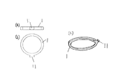
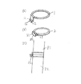
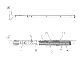
次に、本発明の実施例に係る折り畳み式杖を、図面を参照して説明する。なお、本発明の折り畳み式杖は例えば図11(a)に示すような外観をしているが、折り畳み式杖の折り畳み構造としては従来から用いられている各種形式のものが使用可能であるため、以下の実施例では主に係合突部と係合部とから構成されるロック機構について説明する。また、パイプ内には例えば図11(b)に示すように接続するパイプ同士が引き合うようにコイルスプリングEなどの公知の付勢手段が設けられているが、図示は省略する。なお、付勢手段は必ずしも備えていなくてもよいが、以下の説明では付勢手段を備えているものとして説明する。 Next, a folding cane according to an embodiment of the present invention will be described with reference to the drawings. Although the folding cane of the present invention has an appearance as shown in FIG. 11A, for example, various types of conventionally used folding structures can be used as the folding structure of the folding cane. In the following embodiments, a lock mechanism mainly composed of an engagement protrusion and an engagement portion will be described. In addition, known urging means such as a coil spring E is provided in the pipe so that the pipes to be connected are attracted to each other as shown in FIG. Note that the urging means is not necessarily provided, but in the following description, it is assumed that the urging means is provided.
[実施例1]
本実施例を図1〜図3に基づいて説明する。
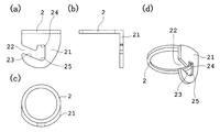
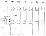
図1は本実施例の折り畳み式杖のロック機構を構成する係合部が設けられた係合部用リングを示す図であり、(a)は正面図、(b)は側面図、(c)は平面図、(d)は斜視図である。図2は本実施例の折り畳み式杖のロック機構を構成する係合突部が設けられた係合突部用リングを示す図であり、(a)は正面図、(b)は平面図、(c)は斜視図である。図3は本実施例の折り畳み式杖のロック機構の係合過程を示す説明図である。
なお、以下の説明において説明の便宜上図3において上側のパイプP1が杖の把手側、下側のパイプP2が杖の石突側であるとするが、パイプP1とパイプP2はこの逆の配置であってもよい。
[Example 1]
This embodiment will be described with reference to FIGS.
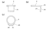
1A and 1B are diagrams showing an engagement portion ring provided with an engagement portion constituting a lock mechanism of a folding cane according to the present embodiment, wherein FIG. 1A is a front view, FIG. 1B is a side view, and FIG. ) Is a plan view, and (d) is a perspective view. FIG. 2 is a diagram showing an engagement projection ring provided with an engagement projection that constitutes the locking mechanism of the folding cane of the present embodiment, (a) is a front view, (b) is a plan view, (C) is a perspective view. FIG. 3 is an explanatory view showing an engagement process of the lock mechanism of the folding cane according to the present embodiment.
In the following description, for convenience of explanation, it is assumed in FIG. 3 that the upper pipe P1 is the handle side of the cane and the lower pipe P2 is the stone protrusion side of the cane, but the pipe P1 and the pipe P2 have the opposite arrangement. May be.
まず、本発明の折り畳み式杖において杖のシャフト用パイプの接続部に備えられるロック機構を構成する係合突部11と係合部21を図1と図2を参照して説明する。
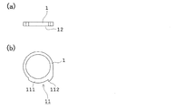
図2に示すように杖のシャフト用のパイプに嵌装可能な径を有する係合突部用リング1の一部にリング外周面から外側へ突出した断面角形の係合突部11が形成されている。図示した例では、係合突部用リング1をプレス加工により形成した例を示したため係合突部11は断面角形であるが、棒状に加工したピンを係合突部に使用する場合は断面円形であってもよい。
First, the engaging
As shown in FIG. 2, an engaging
一方、図1に示すように杖のシャフト用パイプに嵌装可能な径を有する係合部用リング2には係合部21が形成されている。係合部21はパイプP1とパイプP2を回転させた際に係合突部11が係合部21にスライド挿入可能なように一端に開口部22が形成されたスライド挿入部23と、スライド挿入部23に続けて設けられ係合突部21が係合する係合溝24と、軸方向で係合溝24と対向する位置に設けられ係合突部11が当接して係合突部11の軸方向の移動を規制する軸方向移動規制部25とを有している。
On the other hand, as shown in FIG. 1, an
スライド挿入部23は図3(a)に示すように開口部22から係合溝24方向に向かって、石突側から把手方向に傾斜している。また、係合溝24は係合突部11の形状に合わせ断面角形に形成されている。なお、軸方向移動規制部25はパイプP1とパイプP2が引き離される方向に力が作用した際にパイプP1とパイプP2が分離してしまうことを防止できれば図示した形状に限定されるものではない。
As shown in FIG. 3A, the
なお、係合突部用リング1と係合部用リング2は共に金属製であってもよいが、係合突部用リング1を金属製とし係合部用リング2を合成樹脂製としてもよい。係合突部用リング1を金属製とすると、プレス加工により簡単に係合突部用リング1の製造ができる。また、係合部用リング2を合成樹脂製とすると複雑な形状を有する係合部用リング2の成形を簡単に行うことができる。また、係合部用リング2を合成樹脂製とすることにより、係合突部用リング1に形成された係合突部11の摩耗を防止できる。金属の摩耗粉がパイプ内に入ると、折り畳み用の内部機構のスムーズな動きを妨げるおそれがあるため、摩耗粉が発生しない構造にしておくことは有用である。
Both the
そして、図3(a)に示すように係合突部用リング1がパイプP1の接続部に嵌装して取り付けられ、係合部用リング2がパイプP2の接続部に嵌装して取り付けられ本発明の折り畳み式杖で用いられるロック機構を構成している。なお、係合突部11や係合部21は、係合突部用リング1や係合部用リング2を用いず、パイプP1やパイプP2の接続部に直接形成されていてもよく、またその他の方法によりパイプP1やパイプP2に設けられていてもよい。
Then, as shown in FIG. 3 (a), the
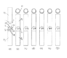
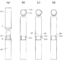
次に、図3を参照してロック機構の係合過程を説明する。説明の便宜上パイプP2は動かさないものとする。なお、図3(b)〜(g)において、上の図は係合部21に対して係合突部11を時計方向に回転させた過程を示す平面図であり、下の図はその時のパイプP1とパイプP2の位置関係を示す正面図である。
まず、パイプP1を図3(a)の位置から図3(b)の位置に差し込む。なお、付勢力によりパイプP1はパイプP2に引き寄せられるため、パイプP1を図3(b)の位置にするために格別の力は要さない。
Next, the engagement process of the lock mechanism will be described with reference to FIG. For convenience of explanation, it is assumed that the pipe P2 is not moved. 3 (b) to 3 (g), the upper diagram is a plan view showing a process in which the
First, the pipe P1 is inserted from the position shown in FIG. 3A to the position shown in FIG. Since the pipe P1 is attracted to the pipe P2 by the urging force, no special force is required to bring the pipe P1 to the position shown in FIG.
この位置において、パイプP1を時計方向に回転させると、図3(c)〜(e)に示すように、パイプP1の係合突部11はパイプP2の係合部21の開口部22からスライド挿入部23に沿ってスライドすることとなる。この過程においては、スライド挿入部23は石突側から把手方向に傾斜しているため付勢力に抗してパイプP1はパイプP2と引き離される方向に移動する。
At this position, when the pipe P1 is rotated clockwise, the
さらにパイプP1を回転させると、図3(f)に示す位置で係合突部11はスライド挿入部23の上死点を超え、最終的に図3(g)に示すように付勢力によりパイプP1はパイプP2に引き寄せられ係合突部11は係合溝24と係合し、パイプP1はパイプP2とロックされることとなる。
When the pipe P1 is further rotated, the engaging
なお、杖使用時に石突がぬかるみなどにはまり、杖を引き抜こうとすることで石突と把手とを引き離すような力が働いても、パイプP1の係合突部11がパイプP2の軸方向移動規制部25に当接し、それ以上のパイプP1の移動は妨げられるため、パイプP1とパイプP2が分離することがない。
Even when a force is applied to pull the cane away by pulling out the cane when the cane is used, the engaging
本ロック機構はこのような基本的な効果の他、パイプの接続が常に同じ位置でロックされることとなるため、パイプに模様がある場合にパイプP1とパイプP2の柄合わせを常に確実に行うことができ、またノルディック用のステッキの場合には把手に対する石突の向きが常に一定であるためパイプ接続の度に石突ゴムの向きを調整する必要がなくなるという効果もある。 In addition to this basic effect, the lock mechanism always locks the pipe connection at the same position. Therefore, when the pipe has a pattern, the patterns of the pipe P1 and the pipe P2 are always reliably aligned. In the case of a Nordic cane, the direction of the bumps with respect to the handle is always constant, so that it is not necessary to adjust the direction of the bumps every time the pipe is connected.
また、本ロック機構を構成する係合突部11を設けた係合突部用リング1や、係合部21を設けたリング2は、既存の折り畳み式杖に後加工により取り付けることも可能であり、両リングをそれぞれのパイプ接続部に取り付けることにより、本発明の折り畳み式杖にできる。
Moreover, the
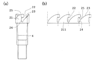
[実施例2]
本実施例を図4〜図7に基づいて説明する。
図4は本実施例の折り畳み式杖のロック機構を構成する係合部が設けられた係合部用リングを示す図であり、(a)は正面図、(b)は側面図、(c)は斜視図である。図5は本実施例の折り畳み式杖のロック機構を構成する係合突部が設けられた係合突部用リングを示す図であり、(a)は正面図、(b)は平面図である。図6は本実施例の折り畳み式杖のロック機構の係合過程を示す説明図である。図7は本施例の変形例を示す図であり、(a)は係合突部用リングの斜視図、(b)は係合部用リングの斜視図、(c)は係合部用リングと係合突部用リングをパイプに取り付けた状態の正面図である。
なお、以下の説明において説明の便宜上図6と図7(c)において上側のパイプP1が杖の把手側、下側のパイプP2が杖の石突側であるとするが、パイプP1とパイプP2はこの逆の配置であってもよい。
[Example 2]
This embodiment will be described with reference to FIGS.
4A and 4B are views showing an engagement portion ring provided with an engagement portion constituting the lock mechanism of the folding cane according to the present embodiment, wherein FIG. 4A is a front view, FIG. 4B is a side view, and FIG. ) Is a perspective view. FIGS. 5A and 5B are diagrams showing an engagement projection ring provided with an engagement projection that constitutes the locking mechanism of the folding cane according to the present embodiment. FIG. 5A is a front view, and FIG. 5B is a plan view. is there. FIG. 6 is an explanatory view showing an engagement process of the lock mechanism of the folding cane according to the present embodiment. FIG. 7 is a view showing a modification of the present embodiment, in which (a) is a perspective view of the ring for engaging projection, (b) is a perspective view of the ring for engaging part, and (c) is for the engaging part. It is a front view of the state which attached the ring and the ring for engagement protrusions to the pipe.
In the following description, for convenience of explanation, it is assumed in FIGS. 6 and 7C that the upper pipe P1 is the handle side of the cane and the lower pipe P2 is the stone side of the cane, but the pipe P1 and the pipe P2 are This arrangement may be reversed.
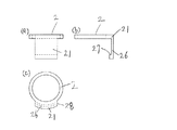
まず、本発明の折り畳み式杖において杖のシャフト用パイプの接続部に備えられるロック機構を構成する係合突部11と係合部21を図4と図5を参照して説明する。
図5に示すように杖のシャフト用のパイプに嵌装可能な径を有する係合突部用リング1の一部に、係合突部用リング1をパイプに嵌装したときパイプの軸方向に対して垂直の方向に係合突部11となる所望の突出量の第1の突出部111と、第1の突出部よりも突出量が大きな第2の突出部112が円周方向に続けて形成されている。
First, the engaging
As shown in FIG. 5, when the
一方、図4に示すように杖のシャフト用パイプに嵌装可能な径を有する係合部用リング2には係合部21が形成されている。係合部21はパイプP1とパイプP2を回転させた際に第1の突出部111の片側の面と摺動する面を有する断面がL字形の鉤部26を有している。図4(b)において鉤部26の下側の内面が摺動面27となっていて、図5(a)において第1の突出部111の片側の面となる摺動部12と回転時に摺動し、係合部21の鉤部26の摺動面27と第1の突出部111の摺動部12が当接するようになっている。また接続完了位置では第2の突出部112が係合部21の端部28に当接するようになっている。
On the other hand, as shown in FIG. 4, an
そして、図6(a)に示すように係合突部用リング1がパイプP1の接続部に嵌装して取り付けられ、係合部用リング2がパイプP2の接続部に嵌装して取り付けられ本発明の折り畳み式杖で用いられるロック機構を構成している。なお、係合突部11や係合部21は、係合突部用リング1や係合部用リング2を用いず、パイプP1やパイプP2の接続部に直接形成されていてもよく、またその他の方法によりパイプP1やパイプP2に設けられていてもよい。
Then, as shown in FIG. 6 (a), the
次に、図6を参照してロック機構の係合過程を説明する。説明の便宜上パイプP2は動かさないものとする。なお、図6(b)〜(d)において、上の図は係合部21に対して第1の突出部111と第2の突出部112を時計方向に回転させた過程を示す平面図であり、下の図はその時のパイプP1とパイプP2の位置関係を示す正面図である。
まず、パイプP1を図6(a)の位置から図6(b)の位置に差し込む。なお、付勢力によりパイプP1はパイプP2に引き寄せられるため、パイプP1を図6(b)の位置にするために格別の力は要さない。
Next, the engagement process of the lock mechanism will be described with reference to FIG. For convenience of explanation, it is assumed that the pipe P2 is not moved. 6B to 6D, the upper diagram is a plan view showing a process in which the first projecting
First, the pipe P1 is inserted from the position of FIG. 6 (a) to the position of FIG. 6 (b). Since the pipe P1 is attracted to the pipe P2 by the urging force, no special force is required to bring the pipe P1 to the position shown in FIG.
この位置において、パイプP1を回転させると、図6(c)に示すようにパイプP1の係合突部11の摺動部12はパイプP2の係合部21の鉤部26の摺動面27と摺動しながら回転することとなる。
When the pipe P1 is rotated at this position, as shown in FIG. 6C, the sliding
さらにパイプP1を回転させると、図6(d)に示すようにパイプP1の第2の突出部112がパイプP2の係合部21の端部28に当接し、パイプP1とパイプP2の接続が完了する。パイプP1とパイプP2は、パイプP1とパイプP2を引き寄せる方向については付勢力によりパイプ同士が接続面で接するように引き寄せられ、また、第1の突出部111の摺動部12と係合部21の鉤部26の摺動面27が当接するためパイプP1とパイプP2が引き離されることはなく、最終的にパイプP1はパイプP2とロックされることとなる。
When the pipe P1 is further rotated, as shown in FIG. 6D, the second projecting
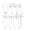
次に、図7を参照して本実施例の変形例について説明する。
図7(a)に示すように杖のシャフト用のパイプに嵌装可能な径を有する係合突部用リング1の一部に、係合突部用リング1をパイプに嵌装したときパイプの軸方向に対して垂直の方向に係合突部11となる所望の突出量の第1の突出部111と、第1の突出部よりも突出量が大きな第2の突出部112が円周方向に続けて形成されている。
Next, a modification of the present embodiment will be described with reference to FIG.
As shown in FIG. 7 (a), when the
一方、図7(b)に示すように杖のシャフト用パイプに嵌装可能な径を有する係合部用リング2には係合部21が形成されている。係合部21はパイプP1とパイプP2を回転させた際に第1の突出部111と第2の突出部112が挿入可能な断面がコの字形の溝部29を有している。また、溝部29の内部に接続完了位置で第2の突出部112が当接する回転規制部291が設けられている。
On the other hand, as shown in FIG. 7B, an
本例の場合は、図7(c)に示すように第1の突出部111と第2の突出部112双方の上面と下面が係合部2の溝部29の上面と下面と摺動するようにして保持され、接合完了時には第1の突出部111と第2の突出部112は係合部2の溝部29により、パイプ同士を引き寄せる方向と引き離す方向の双方について動きが規制されるようにロックされる。また、第2の突出部112は係合部2の溝部29の内部に設けられた回転規制部291に当接するため、接続完了時に第2の突出部112は溝部29内に位置するため、第2の突出部112の出っ張りが杖使用時の支障となるようなことを防止できる。
In the case of this example, as shown in FIG. 7C, the upper and lower surfaces of both the
[実施例3]
本実施例を図8〜図10を参照して説明する。
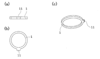
図8は本実施例の折り畳み式杖のロック機構を構成する係合突部が設けられたパイプ接続部となる凸状継手の正面図である。図9は本実施例の折り畳み式杖のロック機構を構成する係合部が設けられたパイプ接続部となる凹状継手を示す図であり、(a)は正面図、(b)は係合部の展開図である。図10は本実施例の折り畳み式杖のロック機構の係合過程を示す説明図である。
なお、以下の説明において説明の便宜上、図10においてパイプP1が連結される凸状継手3が杖の把手側、パイプP2が連結される凹状継手4が杖の石突側であるとするが、凸状継手3と凹状継手4はこの逆の配置であってもよい。
[Example 3]
This embodiment will be described with reference to FIGS.
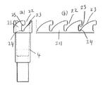
FIG. 8 is a front view of a convex joint serving as a pipe connecting portion provided with an engaging projection that constitutes the locking mechanism of the folding cane according to the present embodiment. FIG. 9 is a view showing a concave joint that becomes a pipe connecting portion provided with an engaging portion constituting the locking mechanism of the folding cane according to the present embodiment, where (a) is a front view, and (b) is an engaging portion. FIG. FIG. 10 is an explanatory view showing an engagement process of the lock mechanism of the folding cane according to the present embodiment.
In the following description, for convenience of explanation, it is assumed in FIG. 10 that the convex joint 3 to which the pipe P1 is connected is the handle side of the cane and the concave joint 4 to which the pipe P2 is connected is the stone protrusion side of the cane. The
まず、本発明の折り畳み式杖において杖のシャフト用パイプの接続部に備えられるロック機構を構成する係合突部11と係合部21について、杖のシャフト用パイプの接続部となる凸状継手に設ける係合突部11を図8を参照して、また凹状継手に設ける係合部21を図9を参照して説明する。
First, in the foldable cane of the present invention, a convex joint that serves as a connecting portion of a cane shaft pipe with respect to the engaging
図8に示すように凸状継手3には、丸棒状に加工したピンが継手に左右対称に埋め込まれ端部が係合突部11となっている。なお、係合突部11は一箇所でもよく、あるいは等間隔で係合部21に数に応じて複数設けてもよい。
As shown in FIG. 8, in the
一方、図9に示すように凹状継手4には係合部21が等間隔で4か所形成されている。係合部21はパイプP1とパイプP2を回転させた際に係合突部11が係合部21にスライド挿入可能なように一端に開口部22が形成されたスライド挿入部23と、スライド挿入部23に続けて設けられ係合突部11と係合する係合溝24と、軸方向で係合溝24と対向する位置に設けられ係合突部11が当接して係合突部11の軸方向の移動が規制される軸方向移動規制部25とを有している。
On the other hand, as shown in FIG. 9, the
スライド挿入部23は図10(a)に示すように開口部22から係合溝24方向に向かって、把手側から石突側方向に傾斜している。また、係合溝24は係合突部11の丸棒形状に合わせ断面円形に形成されている。なお、軸方向移動規制部25はパイプP1とパイプP2が引き離される方向に力が作用した際にパイプP1とパイプP2が分離してしまうことを防止できれば図示した形状に限定されるものではない。
As shown in FIG. 10A, the
また、係合部21は凹状継手4に直接加工して形成してもよいが、例えば図9(b)に示すように係合部21を等間隔で4か所形成した平板上の係合部展開部材211を製作し、これを筒状に丸めて凹状継手4に接合するようにしてもよい。このような方法で係合部21を形成した方が製造上は容易である。
そして、パイプP1に連結された凸状継手3に設けられた係合突部11と、パイプP2に連結された凹状継手4に設けられた係合部21により本発明の折り畳み式杖で用いられるロック機構が構成される。
In addition, the engaging
And it is used with the folding cane of this invention with the engaging
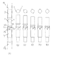
次に、図10を参照してロック機構の係合過程を説明する。説明の便宜上パイプP2は動かさないものとする。なお、図10(b)〜(f)において、上の図は係合部21に対して係合突部11を時計方向に回転させた過程を示す平面図であり、下の図はその時の凸状継手3と凹状継手4の位置関係を示す正面図である。
まず、パイプP1を図10(a)の位置から例えば図10(b)の位置に差し込まれるように位置合わせする。なお、付勢力によりパイプP1はパイプP2に引き寄せられるため、パイプP1を図10(b)の位置にするために格別の力は要さない。また、係合部21は等間隔で4か所設けられているため、係合突部11は必ず係合部21の開口部22を経ていずれかのスライド挿入部23に臨むこととなる。
Next, the engagement process of the lock mechanism will be described with reference to FIG. For convenience of explanation, it is assumed that the pipe P2 is not moved. 10 (b) to 10 (f), the upper diagram is a plan view showing a process in which the
First, the pipe P1 is aligned so as to be inserted from the position of FIG. 10A to the position of FIG. 10B, for example. Since the pipe P1 is attracted to the pipe P2 by the urging force, no special force is required to bring the pipe P1 to the position shown in FIG. In addition, since the
この位置に達した後、スライド挿入部23は開口部22から係合溝23方向に向かって把手側から石突側方向に傾斜しているため、パイプP1は付勢力によりパイプP2側へ引き寄せられ下方へ移動するように自動的に回転する。すなわち、図3(c)〜(f)に示すように、パイプP1の係合突部11はパイプP2の係合部21の開口部22からスライド挿入部23に沿って自動的にスライドし、最終的に係合突部11は係合溝24と係合し、パイプP1はパイプP2とロックされることとなる。したがって、本実施例の場合はパイプP1を意図的に回転させなくても、付勢力によりパイプP1はスライド挿入部23に沿って自動的に回転しながら係合溝24に向かって移動することとなる。
After reaching this position, the
なお、杖使用時に石突がぬかるみなどにはまり、杖を引き抜こうとすることで石突と把手とを引き離すような力が働いても、パイプP1の係合突部11がパイプP2の軸方向移動規制部25と当接し、それ以上のパイプP1の移動は妨げられるため、パイプP1とパイプP2が分離することはない。
Even when a force is applied to pull the cane away by pulling out the cane when the cane is used, the engaging
なお、上記した各実施例では係合突部11がパイプ外周面より外側に突出している例について説明したが、係合突部11はパイプ内周面から内側に突出していてもよい。このようにすると、パイプの外周面にロック機構のための突起物がなくなるため杖としての使用勝手が良くなる。
In each of the above-described embodiments, the example in which the engaging
1 係合突部用リング
11 係合突部
111 第1の突出部
112 第2の突出部
12 摺動部
2 係合部用リング
21 係合部
211 係合部展開部材
22 開口部
23 スライド挿入部
24 係合溝
25 軸方向移動規制部
26 鉤部
27 摺動面
28 端部
29 溝部
291 回転規制部
3 凸状継手
4 凹状継手
P1 把手側パイプ
P2 石突側パイプ
DESCRIPTION OF
Claims (9)
一方のパイプの接続部に該パイプ側面より突出した係合突部を有し、他方のパイプの接続部に前記係合突部と係合する係合部を有し、前記パイプ同士の軸を中心とする相対的な回転により前記係合突部と前記係合部を係合させ、係合位置で少なくとも軸方向への動きを規制するロック機構を備えたことを特徴とする折り畳み式杖。 A foldable cane in which a shaft of a cane is configured by connecting pipes,
The connecting portion of one pipe has an engaging protrusion protruding from the side of the pipe, the connecting portion of the other pipe has an engaging portion that engages with the engaging protrusion, and the axis of the pipes is A folding cane comprising a lock mechanism that engages the engaging protrusion with the engaging portion by relative rotation about a center and restricts movement in at least an axial direction at the engaging position.
Priority Applications (1)
| Application Number | Priority Date | Filing Date | Title |
|---|---|---|---|
| JP2016085516A JP2017192599A (en) | 2016-04-21 | 2016-04-21 | Folding cane |
Applications Claiming Priority (1)
| Application Number | Priority Date | Filing Date | Title |
|---|---|---|---|
| JP2016085516A JP2017192599A (en) | 2016-04-21 | 2016-04-21 | Folding cane |
Publications (1)
| Publication Number | Publication Date |
|---|---|
| JP2017192599A true JP2017192599A (en) | 2017-10-26 |
Family
ID=60154386
Family Applications (1)
| Application Number | Title | Priority Date | Filing Date |
|---|---|---|---|
| JP2016085516A Pending JP2017192599A (en) | 2016-04-21 | 2016-04-21 | Folding cane |
Country Status (1)
| Country | Link |
|---|---|
| JP (1) | JP2017192599A (en) |
Cited By (3)
| Publication number | Priority date | Publication date | Assignee | Title |
|---|---|---|---|---|
| CN108324521A (en) * | 2018-01-08 | 2018-07-27 | 深圳市晓控通信科技有限公司 | A kind of intelligent the eyes of the blind robot with contractile function based on Internet of Things |
| USD1033045S1 (en) | 2023-02-24 | 2024-07-02 | Whipsaw, Inc. | Folding cane |
| USD1033046S1 (en) | 2021-10-28 | 2024-07-02 | Whipsaw, Inc. | Folding cane |
-
2016
- 2016-04-21 JP JP2016085516A patent/JP2017192599A/en active Pending
Cited By (4)
| Publication number | Priority date | Publication date | Assignee | Title |
|---|---|---|---|---|
| CN108324521A (en) * | 2018-01-08 | 2018-07-27 | 深圳市晓控通信科技有限公司 | A kind of intelligent the eyes of the blind robot with contractile function based on Internet of Things |
| CN108324521B (en) * | 2018-01-08 | 2020-04-14 | 南京老人佳智能科技有限公司 | Intelligent blind person stick robot with contraction function based on Internet of things |
| USD1033046S1 (en) | 2021-10-28 | 2024-07-02 | Whipsaw, Inc. | Folding cane |
| USD1033045S1 (en) | 2023-02-24 | 2024-07-02 | Whipsaw, Inc. | Folding cane |
Similar Documents
| Publication | Publication Date | Title |
|---|---|---|
| TWI773770B (en) | Operation stick connection structure | |
| JP5800210B1 (en) | Folding cane | |
| JP2017192599A (en) | Folding cane | |
| JP3686408B2 (en) | Hydraulic conduit connection coupling | |
| US20090245924A1 (en) | Small Handling Pole Locking Assembly | |
| TWM466983U (en) | Positioning device with multiple folded rods | |
| TW201440641A (en) | Connector | |
| RU2012146243A (en) | SLIDING ELEMENT FOR CONNECTING COUPLING | |
| JP2007209418A (en) | Separable or foldable walking stick and pipe joint | |
| US10690278B2 (en) | Coupling assembly with vibration lock | |
| JP2013063258A (en) | Auto-lock type accessory connecting part using magnet | |
| US20180003005A1 (en) | Downhole Shifting Tool | |
| JP7112514B2 (en) | Locking mechanism for quick connect fittings | |
| US2992845A (en) | Friction device | |
| JP5658950B2 (en) | Folding cane | |
| JP2009268856A (en) | Clasp | |
| KR101836922B1 (en) | A device for coupling reinforcing rod | |
| TWI572431B (en) | Cut off the tool | |
| JP2016538489A (en) | Quick coupling | |
| JP2012087837A (en) | Pipe joint | |
| JP6643208B2 (en) | Fishing tackle | |
| TWI730865B (en) | Positioning device for telescopic rod and telescopic rod | |
| JP5878898B2 (en) | Scaffolding coupling device | |
| JP6539082B2 (en) | Joint for support connection and support body | |
| JP6376823B2 (en) | Accessories for connecting accessories and connecting members |