JP2017192586A - Game machines and decorative bodies - Google Patents
Game machines and decorative bodies Download PDFInfo
- Publication number
- JP2017192586A JP2017192586A JP2016085175A JP2016085175A JP2017192586A JP 2017192586 A JP2017192586 A JP 2017192586A JP 2016085175 A JP2016085175 A JP 2016085175A JP 2016085175 A JP2016085175 A JP 2016085175A JP 2017192586 A JP2017192586 A JP 2017192586A
- Authority
- JP
- Japan
- Prior art keywords
- control unit
- command
- game
- special symbol
- winning
- Prior art date
- Legal status (The legal status is an assumption and is not a legal conclusion. Google has not performed a legal analysis and makes no representation as to the accuracy of the status listed.)
- Pending
Links
- 230000000694 effects Effects 0.000 description 326
- 238000000034 method Methods 0.000 description 311
- 230000008569 process Effects 0.000 description 304
- 238000003860 storage Methods 0.000 description 101
- 238000012545 processing Methods 0.000 description 98
- 230000008859 change Effects 0.000 description 69
- 241000722921 Tulipa gesneriana Species 0.000 description 42
- 238000010586 diagram Methods 0.000 description 27
- 238000004519 manufacturing process Methods 0.000 description 27
- 230000002093 peripheral effect Effects 0.000 description 24
- 230000006870 function Effects 0.000 description 23
- 210000000078 claw Anatomy 0.000 description 19
- 238000001514 detection method Methods 0.000 description 19
- 230000009467 reduction Effects 0.000 description 15
- 230000033001 locomotion Effects 0.000 description 13
- 238000005034 decoration Methods 0.000 description 8
- 238000009420 retrofitting Methods 0.000 description 7
- 238000005259 measurement Methods 0.000 description 6
- 230000005540 biological transmission Effects 0.000 description 5
- 238000013461 design Methods 0.000 description 5
- 230000015654 memory Effects 0.000 description 5
- 230000004048 modification Effects 0.000 description 5
- 238000012986 modification Methods 0.000 description 5
- 230000004044 response Effects 0.000 description 5
- 238000012790 confirmation Methods 0.000 description 4
- 230000005611 electricity Effects 0.000 description 4
- 239000011347 resin Substances 0.000 description 4
- 229920005989 resin Polymers 0.000 description 4
- 230000009471 action Effects 0.000 description 3
- 238000004458 analytical method Methods 0.000 description 3
- 230000003287 optical effect Effects 0.000 description 3
- 239000000725 suspension Substances 0.000 description 3
- 230000004913 activation Effects 0.000 description 2
- 230000004397 blinking Effects 0.000 description 2
- 230000001186 cumulative effect Effects 0.000 description 2
- 230000007423 decrease Effects 0.000 description 2
- 230000003247 decreasing effect Effects 0.000 description 2
- 239000011521 glass Substances 0.000 description 2
- 239000004973 liquid crystal related substance Substances 0.000 description 2
- 230000007246 mechanism Effects 0.000 description 2
- 239000000758 substrate Substances 0.000 description 2
- 230000003936 working memory Effects 0.000 description 2
- 240000005924 Stenocarpus sinuatus Species 0.000 description 1
- 230000002159 abnormal effect Effects 0.000 description 1
- 238000005452 bending Methods 0.000 description 1
- 238000004364 calculation method Methods 0.000 description 1
- 230000001055 chewing effect Effects 0.000 description 1
- 230000029087 digestion Effects 0.000 description 1
- 238000006073 displacement reaction Methods 0.000 description 1
- 230000005489 elastic deformation Effects 0.000 description 1
- 238000010304 firing Methods 0.000 description 1
- 230000006872 improvement Effects 0.000 description 1
- 239000002184 metal Substances 0.000 description 1
- 239000012466 permeate Substances 0.000 description 1
- 230000002265 prevention Effects 0.000 description 1
- 239000000047 product Substances 0.000 description 1
- YIXCPMSISWSKKS-FGCOXFRFSA-N ram-333 Chemical compound C1([C@]23CCN(C)[C@@H]([C@@]2(CCCC3)O)CC1=CC=C1OC)=C1OC1=CC=CC=C1 YIXCPMSISWSKKS-FGCOXFRFSA-N 0.000 description 1
- 238000011084 recovery Methods 0.000 description 1
- 230000008439 repair process Effects 0.000 description 1
- 230000007480 spreading Effects 0.000 description 1
- 238000003892 spreading Methods 0.000 description 1
- CCEKAJIANROZEO-UHFFFAOYSA-N sulfluramid Chemical group CCNS(=O)(=O)C(F)(F)C(F)(F)C(F)(F)C(F)(F)C(F)(F)C(F)(F)C(F)(F)C(F)(F)F CCEKAJIANROZEO-UHFFFAOYSA-N 0.000 description 1
- 239000010409 thin film Substances 0.000 description 1
- 238000012546 transfer Methods 0.000 description 1
- 230000001960 triggered effect Effects 0.000 description 1
Images


Landscapes
- Pinball Game Machines (AREA)
Abstract
Description
本発明は、遊技球の入賞によって大当たりの抽選を行うパチンコ遊技機や、遊技媒体の投入の際の抽選結果を複数リールの停止時に図柄の組み合わせで表示するスロットマシン等の遊技機に関するものである。 The present invention relates to a gaming machine such as a pachinko gaming machine that draws a jackpot by winning a game ball, or a slot machine that displays a lottery result when a game medium is inserted in a combination of symbols when a plurality of reels are stopped. .
例えば、特許文献1には、ガラス枠を外枠に対して閉止状態とすると、遊技盤に取り付けられた装飾ランプがランプ用孔に突入して、ガラス枠の前側へ突出するので、あたかも装飾ランプが前面枠に備えられているように見せることができることが開示されている。
For example, in
本発明は、興趣性を高めた遊技機などを提供することを目的とする。 An object of this invention is to provide the game machine etc. which improved the interest property.
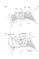
上記の目的を達成する本発明は、次のような遊技機として実現される。この遊技機は、所定の演出を行う遊技機(例えば、パチンコ遊技機100)であって、筺体(例えば、外枠10)と、前記筺体に開閉可能に設けられる扉(例えば、前面枠20)と、前記扉に着脱可能に設けられる装飾体(例えば、後付装飾体6)とを有することを特徴とすることができる。
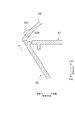
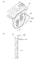
また、本発明は、次のような装飾体として実現される。この装飾体(例えば、後付装飾体6)は、所定の演出を行う遊技機(例えば、パチンコ遊技機100)の筺体(例えば、外枠10)に対して開閉可能に設けられる扉(例えば、前面枠20)に着脱可能に設けられる着脱部(例えば、固定板67)と、前記着脱部によって支持され、当該着脱部を介して前記扉に設けられる基体(例えば、前板65)とを有することを特徴とすることができる。
The present invention that achieves the above object is realized as the following gaming machine. This gaming machine is a gaming machine (for example, a pachinko gaming machine 100) that performs a predetermined performance, and includes a housing (for example, the outer frame 10) and a door (for example, the front frame 20) that can be opened and closed on the housing. And a decorative body (for example, a retrofit decorative body 6) detachably provided on the door.
Moreover, this invention is implement | achieved as a decorative body as follows. The decorative body (for example, the retrofit decorative body 6) is a door (for example, a door) that can be opened and closed with respect to a housing (for example, the outer frame 10) of a gaming machine (for example, a pachinko gaming machine 100) that performs a predetermined effect. An detachable portion (for example, a fixed plate 67) provided detachably on the front frame 20) and a base (for example, a front plate 65) supported by the detachable portion and provided on the door via the detachable portion. Can be characterized.
なお、本欄における上記符号は、本発明の説明に際して例示的に付したものであり、この符号により本発明が減縮されるものではない。 In addition, the said code | symbol in this column is attached | subjected illustratively in the description of this invention, and this invention is not reduced by this code | symbol.
本発明によれば、興趣性を高めた遊技機などを提供することができる。 According to the present invention, it is possible to provide a gaming machine or the like with enhanced interest.
以下、添付図面を参照して、本発明の実施の形態について詳細に説明する。
〔遊技機の基本構成〕
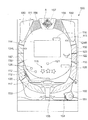
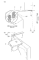
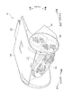
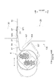
図1は、本実施の形態に係るパチンコ遊技機100の概略正面図である。
図1に示す遊技機の一例としてのパチンコ遊技機100は、遊技者の指示操作により打ち出された遊技球が入賞すると賞球を払い出すように構成されたものである。このパチンコ遊技機100は、遊技球が打ち出される遊技盤110と、遊技盤110を囲む枠部材150と、枠部材150から突出する後付装飾体6とを備えている。遊技盤110は、枠部材150に着脱自在に取り付けられている。また、後付装飾体6は、枠部材150に着脱自在に取り付けられている。
なお、以下の説明において、図1に示すパチンコ遊技機100の紙面上側と紙面下側との方向を上下方向と称し、紙面左側と紙面右側との方向を左右方向と呼ぶ。さらに、図1に示すパチンコ遊技機100に対して遊技者が遊技をする側を前側と呼び、その逆側を後側と呼ぶ。
Embodiments of the present invention will be described below in detail with reference to the accompanying drawings.
[Basic configuration of gaming machine]
FIG. 1 is a schematic front view of a
A
In the following description, the direction of the upper side and the lower side of the paper surface of the
遊技盤110は、前面に、遊技球により遊技を行うための遊技領域111と、下方から発射された遊技球が上昇して遊技領域111の上部位置へ向かう通路を形成するレール部材112と、遊技領域111の右側に遊技球を案内する案内部材113とを備えている。
本実施の形態では、遊技者により視認され易い遊技領域111の位置に、演出のための各種の画像を表示する画像表示部114が配設されている。この画像表示部114は、液晶ディスプレイ等による表示画面を備え、遊技者によるゲームの進行に伴い、例えば、図柄抽選結果(図柄変動結果)を遊技者に報知するための装飾図柄を表示したり、キャラクタの登場やアイテムの出現による演出画像や後述の保留表示を用いた演出画像を表示したりする。
また、遊技盤110の前面に、各種の演出に用いられる可動役物115および盤ランプ116を備えている。可動役物115は、遊技盤110上で動作することにより各種の演出を行い、また、盤ランプ116は、発光することで各種の演出を行う。
The
In the present embodiment, an
In addition, a
遊技領域111には、遊技球が落下する方向に変化を与えるための図示しない遊技くぎおよび風車等が配設されている。また、遊技領域111には、入賞や抽選に関する種々の役物が所定の位置に配設されている。また、遊技領域111には、遊技領域111に打ち出された遊技球のうち入賞口に入賞しなかったものを遊技領域111の外に排出する排出口117が配設されている。
The
本実施の形態では、入賞や抽選に関する種々の役物として、遊技球が入賞すると特別図柄抽選(大当たり抽選)が始動する第1始動口121および第2始動口122と、遊技球が通過すると普通図柄抽選(開閉抽選)が始動する始動ゲート(以下、単にゲートと呼ぶ)124と、が遊技盤110に配設されている。なお、図1において、ゲート124は、遊技領域111の左右にそれぞれ設けられており、左側のゲート124は124Lと記載し、右側のゲート124は124Rと記載している。また、ここにいう第1始動口121および第2始動口122とは、予め定められた1の特別図柄表示器の作動契機となる入賞口をいう。具体的には、第1始動口121および第2始動口122には、入賞の際に遊技球の通過を検知するスイッチ(後述の第1始動口スイッチ211および第2始動口スイッチ212)が設けられている。そして、第1始動口121または第2始動口122に遊技球が入賞した際にこのスイッチが遊技球の通過を検知することが、特別図柄表示器を作動させる契機となる。
In the present embodiment, as various functions related to winning and lottery, a special symbol lottery (a jackpot lottery) starts when a game ball wins, and it is normal when a game ball passes. A start gate (hereinafter simply referred to as a gate) 124 for starting a symbol lottery (open / close lottery) is disposed on the
第2始動口122は、チューリップの花の形をした一対の羽根が電動ソレノイドにより開閉すると共に点灯する普通電動役物としての電動チューリップ(開閉部材)123を備えている。電動チューリップ123は、羽根が閉じていると、遊技球が第2始動口122へ入り難い一方で、羽根が開くと第2始動口122の入口が拡大して遊技球が第2始動口122へ入り易くなるように構成されている。そして、電動チューリップ123は、普通図柄抽選に当選すると、点灯ないし点滅しながら羽根が規定時間(例えば0.15秒ないし1.8秒間)および規定回数(例えば1回ないし3回)だけ開く。
The
パチンコ遊技機100は、遊技状態として、大当たり抽選の当選確率に基づき、当選確率の低い低確率状態と、低確率状態よりも当選確率の高い高確率状態とを有している。そして、所定の条件において低確率状態と高確率状態とのいずれかの状態に制御される。また、パチンコ遊技機100は、第2始動口122への入賞機会が少ない時短無状態と、時短無状態よりも第2始動口122への入賞機会が多い時短状態とを有している。そして、所定の条件において、時短無状態と、時短状態とのいずれかの状態に制御される。時短状態とは、たとえば、普通図柄抽選の当たり当選確率を高確率にする、普通図柄変動時間を短縮する、あるいは電動チューリップ123の開時間を延長する、のいずれか一つまたは複数の組合せによって制御される遊技状態である。なお、時短状態では、特別図柄の特別図柄変動時間が短縮されていてもよい。
The
また、本実施の形態では、入賞や抽選に関するその他の役物として、特別図柄抽選の結果に応じて開放する特別電動役物としての大入賞口125と、遊技球が入賞しても抽選を行わない普通入賞口126と、が遊技盤110に配設されている。
本実施の形態では、遊技盤110の右下の位置に、抽選結果や保留数に関する表示を行う表示器130が配設されている。
Also, in this embodiment, as other prizes and lottery items, a lottery is performed even if a game ball wins a grand prize opening 125 as a special electric bonus that opens according to the result of the special symbol lottery. An ordinary winning
In the present embodiment, a
また、遊技盤110の裏面には、特別図柄の当選の判定等を行う遊技制御基板、演出を統括的に制御する演出制御基板、画像および音による演出を制御する画像制御基板、各種のランプおよび可動役物115による演出を制御するランプ制御基板などの図示しない各種の基板等が取り付けられる。また、遊技盤110の裏面には、供給された24VのAC電源をDC電源に変換して各種の基板等に出力するスイッチング電源(不図示)が配設されている。
Also, on the back side of the
枠部材150は、遊技者がハンドル151に触れてレバー152を時計方向に回転させる操作を行うとその操作角度に応じた打球力にて遊技球を所定の時間間隔(例えば1分間に100個)で電動発射する発射装置(不図示)を備えている。また、枠部材150は、遊技者のレバー152による操作と連動したタイミングで発射装置に遊技球を1つずつ順に供給する供給装置(不図示)と、供給装置が発射装置に供給する遊技球を一時的に溜めておく皿153と、を備えている。この皿153には、例えば払い出しユニットによる払出球が払い出される。
なお、本実施の形態では、皿153を上下皿一体で構成しているが、上皿と下皿とを分離する構成例も考えられる。また、発射装置のハンドル151を所定条件下で発光させる構成例も考えられる。
When the player touches the
In the present embodiment, the
また、枠部材150は、発射装置のハンドル151に遊技者が触れている状態であっても遊技球の発射を一時的に停止させるための停止ボタン154と、皿153に溜まっている遊技球を箱(不図示)に落下させて取り出すための取り出しボタン155と、を備えている。
また、枠部材150は、パチンコ遊技機100の遊技状態や状況を告知したり各種の演出を行ったりするスピーカ156および枠ランプ157を備えている。スピーカ156は、楽曲や音声、効果音による各種の演出を行う。枠ランプ157は、LED等の発光体で構成され、点灯・点滅によるパターンや発光色の違い等で光による各種の演出を行う。なお、枠ランプ157については、光の照射方向を変更する演出を行うことを可能にする構成例が考えられる。
また、枠部材150は、遊技盤110を遊技者と隔てるともに、パチンコ遊技機100の外面を構成する透明板90(図34参照)を備えている。
The
Further, the
Further, the
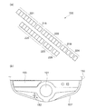
図2は、本実施の形態に係るパチンコ遊技機100を説明する図であり、図2(a)は、遊技盤110の右下に配設された表示器130の一例を示す拡大図であり、図2(b)は、パチンコ遊技機100の部分平面図である。
パチンコ遊技機100の表示器130は、図2(a)に示すように、第1始動口121の入賞に対応して作動する第1特別図柄表示器221と、第2始動口122の入賞に対応して作動する第2特別図柄表示器222と、ゲート124の通過に対応して作動する普通図柄表示器223と、を備えている。第1特別図柄表示器221は、第1始動口121の入賞に基づき、特別図柄を変動表示した後に停止させて抽選結果を表示する。第2特別図柄表示器222は、第2始動口122の入賞に基づき、特別図柄を変動表示した後に停止させて抽選結果を表示する。普通図柄表示器223は、遊技球がゲート124を通過したことに基づき、普通図柄を変動表示した後に停止させて抽選結果を表示する。本実施の形態では、第1特別図柄表示器221、第2特別図柄表示器222は、各々LEDを配列した表示装置で構成され、その点灯態様によって特別図柄抽選の抽選結果が表示される。同様に、普通図柄表示器223も、LEDを配列した表示装置で構成され、その点灯態様によって普通図柄抽選の抽選結果が表示される。
FIG. 2 is a view for explaining the
As shown in FIG. 2A, the
また、表示器130は、第1特別図柄表示器221での保留に対応して作動する第1特別図柄保留表示器218と、第2特別図柄表示器222での保留に対応して作動する第2特別図柄保留表示器219と、普通図柄表示器223での保留に対応して作動する普通図柄保留表示器220と、を備えている。本実施の形態では、第1特別図柄保留表示器218、第2特別図柄保留表示器219および普通図柄保留表示器220は、各々LEDを配列した表示装置で構成され、その点灯態様によって保留数が表示される。
In addition, the
ここで、保留について説明する。特別図柄の変動表示動作中(入賞1回分の変動表示が行なわれている間)にさらに第1始動口121または第2始動口122に遊技球が入賞した場合、特別図柄が変動中であるために、後の入賞に基づく特別図柄の変動表示動作を開始することができない。そのため、後の入賞は規定個数(例えば4個)を限度に記憶され、その入賞した遊技球に対する特別図柄を始動させるための権利が、先に入賞した遊技球に対する変動表示動作が終了するまで、保留される。
なお、普通図柄に関しても、特別図柄と同様の処理を行う。このような保留がなされていることおよびその保留の数(未変動数)が、第1特別図柄保留表示器218、第2特別図柄保留表示器219および普通図柄保留表示器220に表示される。
Here, the hold will be described. If a game ball wins in the
For normal symbols, the same processing as for special symbols is performed. The fact that such a hold has been made and the number of hold (unchanged number) are displayed on the first special
さらに、表示器130は、パチンコ遊技機100の状態を表示する状態表示器224を備えている。本実施の形態では、状態表示器224は、3個のLEDを配列した表示装置で構成されている。3個のLEDのうち1つは、パチンコ遊技機100の状態が、特別図柄抽選の当選確率が高確率である高確率状態となっているか否かを点灯により報知するものである。また、他の1つは、パチンコ遊技機100の状態が、第2始動口122に入賞しやすい時短状態となっているか否かを点灯により報知するものである。さらに他の1つは、右打ちすることによって(遊技球の打球力を変更することによって)遊技者に有利な状態となっているか否かを点灯により報知するものである。
Furthermore, the
なお、状態表示器224が表示するパチンコ遊技機100の状態は上記の例に限らず、他の状態を表示することができる。例えばパチンコ遊技機100の状態として低確率状態よりも当選確率が高く高確率状態よりは当選確率が低い中確率状態が設定される場合、状態表示器224は、中確率状態となっているか否かを点灯により報知しても良い。
The state of the
また、表示器130は、特別図柄抽選の抽選結果に応じて行われる大当たり遊技において大入賞口125が作動される際のラウンド数を表示するラウンド数表示器225を備えている。なお、大当たり遊技については後述する。ラウンド数表示器225は、LEDを配列した表示装置で構成され、その点灯態様によって大当たり遊技における大入賞口125の作動ラウンド数が表示される。
In addition, the
パチンコ遊技機100の枠部材150は、遊技者が演出に対する入力を行うための入力装置を備えている。図2(b)に示すように、本実施の形態では、入力装置の一例として、演出ボタン161と、演出ボタン161に隣接し、略十字に配列された複数のキーからなる演出キー162と、が枠部材150に配設されている。図示の例において、遊技者は、例えば、十字に配列された4つのキーからなる演出キー162を操作することにより、画像表示部114に表示されている複数の画像の何れかを指示することが可能であり、また、演出ボタン161を操作することにより、指示した画像を選択することが可能である。また、入力装置の形態としては、図示した演出ボタン161および演出キー162の他、レバーやダイヤル等、演出の内容等に応じて様々な入力形態を採用することができる。
The
〔制御ユニットの構成〕
次に、パチンコ遊技機100での動作制御や信号処理を行う制御ユニットについて説明する。
図3は、制御ユニットの内部構成を示すブロック図である。図3に示すように、制御ユニットは、メイン制御手段として、特別図柄の当選の判定等を行う遊技制御部200を備えている。また、サブ制御手段として、演出を統括的に制御する演出制御部300と、画像および音響を用いた演出を制御する画像/音響制御部310と、各種のランプおよび可動役物115を用いた演出を制御するランプ制御部320と、払出球の払い出し制御を行う払出制御部330と、を備えている。
[Configuration of control unit]
Next, a control unit that performs operation control and signal processing in the
FIG. 3 is a block diagram showing an internal configuration of the control unit. As shown in FIG. 3, the control unit includes a
前述したように、遊技制御部200、演出制御部300、画像/音響制御部310、ランプ制御部320、および払出制御部330各々は、遊技盤110の後面に配設されたメイン基板としての遊技制御基板、サブ基板としての演出制御基板、画像制御基板、ランプ制御基板、および払出制御基板において個別に構成されている。
As described above, the
〔遊技制御部の構成・機能〕
遊技制御部200は、特別図柄の当選の判定等を行う際の演算処理を行うCPU201と、CPU201にて実行されるプログラムや各種データ等が記憶されたROM202と、CPU201の作業用メモリ等として用いられるRAM203と、を備えている。
遊技制御部200は、第1始動口121または第2始動口122に遊技球が入賞すると特別図柄抽選を行い、その抽選結果を演出制御部300に送る。また、高確率状態と低確率状態の変更情報、時短無状態と時短状態の変更情報を演出制御部300に送る。
さらに、遊技制御部200は、普通図柄抽選の当たり当選確率を高確率にする、普通図柄変動時間を短縮する、あるいは電動チューリップ123の開時間を延長する制御を行う。また、遊技制御部200は、遊技球が連続的に第1始動口121または第2始動口122へ入賞したときの未変動分の限度個数(例えば4個)までの保留や、遊技球が連続的にゲート124を通過したときの未変動分の限度個数(例えば4個)までの保留を設定する。
さらにまた、遊技制御部200は、特別図柄抽選の結果に応じて、特別電動役物である大入賞口125が所定条件(例えば29.5秒経過または遊技球10個の入賞)を満たすまで開状態を維持するラウンドを所定回数だけ繰り返すように制御する。さらには、大入賞口125が開く際の開閉動作間隔を制御する。
[Configuration and function of game control unit]
The
When the game ball wins the
Further, the
Furthermore, the
さらに、遊技制御部200は、第1始動口121、第2始動口122、大入賞口125および普通入賞口126に遊技球が入賞すると、遊技球が入賞した場所に応じて1つの遊技球当たり所定数の賞球を払い出すように、払出制御部330に対する指示を行う。例えば、第1始動口121に遊技球が入賞すると3個の賞球、第2始動口122に遊技球が入賞すると4個の賞球、大入賞口125に遊技球が入賞すると13個の賞球、普通入賞口126に遊技球が入賞すると10個の賞球をそれぞれ払い出すように、払出制御部330に指示命令(コマンド)を送る。なお、ゲート124を遊技球が通過したことを検出しても、それに連動した賞球の払い出しは払出制御部330に指示しない。
払出制御部330が遊技制御部200の指示に従って賞球の払い出しを行った場合には、遊技制御部200は、払い出した賞球の個数に関する情報を払出制御部330から取得する。それにより、払い出した賞球の個数を管理する。
Further, when the game ball is won in the
When the
遊技制御部200には、検知手段として、図3に示すように、第1始動口121への遊技球の入賞を検出する第1始動口検出部(第1始動口スイッチ(SW))211と、第2始動口122への遊技球の入賞を検出する第2始動口検出部(第2始動口スイッチ(SW))212と、電動チューリップ123を開閉する電動チューリップ開閉部213と、ゲート124への遊技球の通過を検出するゲート検出部(ゲートスイッチ(SW))214と、が接続されている。
さらに、遊技制御部200には、大入賞口125への遊技球の入賞を検出する大入賞口検出部(大入賞口スイッチ(SW))215と、大入賞口125を閉状態と突出傾斜した開状態とに設定する大入賞口開閉部216と、普通入賞口126への遊技球の入賞を検出する普通入賞口検出部(普通入賞口スイッチ(SW))217と、が接続されている。
As shown in FIG. 3, the
Further, the
また、遊技制御部200には、特別図柄の変動中に第1始動口121へ入賞した未変動分の保留個数を限度個数内(例えば4個)で表示する第1特別図柄保留表示器218と、特別図柄の変動中に第2始動口122へ入賞した未変動分の保留個数を限度個数内で表示する第2特別図柄保留表示器219と、普通図柄の変動中にゲート124を通過した未変動分の保留個数を限度個数内で表示する普通図柄保留表示器220と、が接続されている。
さらに、遊技制御部200には、第1始動口121への遊技球の入賞により行われる特別図柄の変動表示および特別図柄抽選の結果を表示する第1特別図柄表示器221と、第2始動口122への遊技球の入賞により行われる特別図柄の変動表示および特別図柄抽選の結果を表示する第2特別図柄表示器222と、普通図柄の変動表示および普通図柄抽選の結果を表示する普通図柄表示器223と、パチンコ遊技機100の状態を表示する状態表示器224と、が接続されている。
In addition, the
Further, the
そして、第1始動口スイッチ211、第2始動口スイッチ212、ゲートスイッチ214、大入賞口スイッチ215および普通入賞口スイッチ217にて検出された検出信号が、遊技制御部200に送られる。また、遊技制御部200からの制御信号が、電動チューリップ開閉部213、大入賞口開閉部216、第1特別図柄保留表示器218、第2特別図柄保留表示器219、普通図柄保留表示器220、第1特別図柄表示器221、第2特別図柄表示器222、普通図柄表示器223および状態表示器224に送られる。それにより、遊技制御部200は、上記した払い出し賞球数に関連する各種制御を行う。
Then, detection signals detected by the first
さらに、遊技制御部200には、ホールに設置されたホストコンピュータ(不図示)に対して各種の情報を送信する盤用外部情報端子基板350が接続されている。そして、遊技制御部200は、払出制御部330から取得した、払い出した賞球数に関する情報や遊技制御部200の状態等を示す情報を、盤用外部情報端子基板350を介してホストコンピュータに送信する。
Further, a board external
〔演出制御部の構成・機能〕
演出制御部300は、演出を制御する際の演算処理を行うCPU301と、CPU301にて実行されるプログラムや各種データ等が記憶されたROM302と、CPU301の作業用メモリ等として用いられるRAM303と、日時を計測するリアルタイムクロック(RTC)304と、を備えている。
演出制御部300は、例えば遊技制御部200から送られる特別図柄抽選での当選か否かの判定結果および変動パターンに基づいて、演出内容を設定する。その際、演出ボタン161または演出キー162を用いたユーザからの操作入力を受けて、操作入力に応じた演出内容を設定する場合もある。この場合、例えば演出ボタン161等のコントローラ(不図示)から操作に応じた信号(操作信号)を受け付け、この操作信号により識別される操作内容を演出の設定に反映させる。
また、演出制御部300は、遊技が所定期間中断された場合には、演出の一つとして客待ち用の画面表示の設定を指示する。
さらには、演出制御部300は、遊技制御部200より受信した高確率状態と低確率状態の変更情報、時短無状態と時短状態の変更情報に基づいて演出内容を設定する。
また、演出制御部300は、設定した演出内容の実行を指示するコマンドを画像/音響制御部310およびランプ制御部320に送る。
[Configuration and function of production control unit]
The effect control unit 300 includes a
The effect control unit 300 sets the contents of the effect, for example, based on the determination result of whether or not the winning in the special symbol lottery sent from the
In addition, when the game is interrupted for a predetermined period, the effect control unit 300 instructs the setting of the screen display for waiting for a customer as one of the effects.
Furthermore, the production control unit 300 sets the production content based on the change information of the high probability state and the low probability state received from the
In addition, the effect control unit 300 sends a command for instructing execution of the set effect contents to the image /
〔画像/音響制御部の構成・機能〕
画像/音響制御部310は、演出内容を表現する画像および音響を制御する際の演算処理を行うCPU311と、CPU311にて実行されるプログラムや各種データ等が記憶されたROM312と、CPU311の作業用メモリ等として用いられるRAM313と、VDP(Video Display Processor)314と、CGROM315と、SNDROM316とを備えている。
[Configuration / Function of Image / Sound Control Unit]
The image /
そして、画像/音響制御部310は、演出制御部300から送られたコマンドに基づいて、画像表示部114に表示する画像およびスピーカ156から出力する音響を制御する。
具体的には、CGROM315には、画像表示部114において遊技中に表示する図柄画像や背景画像、遊技者に抽選結果を報知するための装飾図柄、遊技者に予告演出を表示するためのキャラクタやアイテム等といった画像データが記憶されている。また、SNDROM316には、画像データと同期させて、または画像データとは独立にスピーカ156から出力させる楽曲や音声、さらにはジングル等の効果音等といった各種音響データが記憶されている。
CPU311は、演出制御部300から送られた保留数コマンドもしくは変動開始コマンドに基づいて、アニメーションパターンの解析や、描画に関するコマンドをまとめたディスプレイリストの作成、およびディスプレイリストのVDP314への送信などを行う。
Then, the image /
Specifically, the
Based on the hold number command or the change start command sent from the effect control unit 300, the
VDP314は、CPU311から受信したディスプレイリストに基づいて、CGROM315やSNDROM316にそれぞれ記憶された画像データや音響データ読み出す。さらには、VDP314は、読み出した画像データを用いて背景画像表示、図柄画像表示、図柄画像変動、およびキャラクタ/アイテム表示等のための描画処理と、読み出した音響データを用いた音声処理とを行う。そして、VDP314は、描画処理された画像データにより画像表示部114での画面表示を制御する。また、VDP314は、音声処理された音響データによりスピーカ156から出力される音響を制御する。
なお、本実施の形態では、VDP314が描画処理に併せて音声処理も行うよう構成しているが、これに限定されず、音声処理を専用で行うプロセッサを別途設けても構わない。
The VDP 314 reads image data and acoustic data stored in the
In the present embodiment, the VDP 314 is configured to perform audio processing in addition to the drawing processing. However, the present invention is not limited to this, and a processor that performs dedicated audio processing may be provided separately.
〔ランプ制御部の構成・機能〕
ランプ制御部320は、盤ランプ116や枠ランプ157の発光、および可動役物115の動作を制御する際の演算処理を行うCPU321と、CPU321にて実行されるプログラムや各種データ等が記憶されたROM322と、CPU321の作業用メモリ等として用いられるRAM323と、を備えている。
そして、ランプ制御部320は、演出制御部300から送られたコマンドに基づいて、盤ランプ116や枠ランプ157の点灯/点滅や発光色等を制御する。また、可動役物115の動作を制御する。
[Configuration and function of lamp control unit]
The
The
具体的には、ランプ制御部320のROM322には、演出制御部300にて設定される演出内容に応じた盤ランプ116や枠ランプ157での点灯/点滅パターンデータおよび発光色パターンデータ(発光パターンデータ)が記憶されている。CPU321は、ROM322に記憶された発光パターンデータの中から、演出制御部300から送られたコマンドに対応したものを選択して読み出す。そして、ランプ制御部320は、読み出した発光パターンデータにより盤ランプ116や枠ランプ157の発光を制御する。
また、ランプ制御部320のROM322には、演出制御部300にて設定される演出内容に応じた可動役物115の動作パターンデータが記憶されている。CPU321は、可動役物115に対しては、読み出した動作パターンデータによりその動作を制御する。
Specifically, the
The
〔払出制御部の構成・機能〕
払出制御部330は、払出球の払い出しを制御する際の演算処理を行うCPU331と、CPU331にて実行されるプログラムや各種データ等が記憶されたROM332と、CPU331の作業用メモリ等として用いられるRAM333と、を備えている。
そして、払出制御部330は、遊技制御部200から送られたコマンドに基づいて、払出球の払い出しを制御する。
具体的には、払出制御部330は、遊技制御部200から、遊技球が入賞した場所(第1始動口121等)に応じた所定数の賞球を払い出すコマンドを取得する。そして、コマンドに指定された数だけの賞球を払い出すように払出駆動部334を制御する。ここでの払出駆動部334は、遊技球の貯留部から遊技球を送り出す駆動モータで構成される。
[Configuration and function of payout control unit]
The
The
Specifically, the
また、払出制御部330には、払出駆動部334により遊技球の貯留部から実際に払い出された賞球の数を検出する払出球検出部335と、貯留部(不図示)での遊技球の貯留の有無を検出する球有り検出部336と、遊技者が遊技する際に使用する遊技球や払い出された賞球が保持される皿153が満タン状態に有るか否かを検出する満タン検出部337と、が接続されている。そして、払出制御部330は、払出球検出部335、球有り検出部336および満タン検出部337にて検出された検出信号を受け取り、これらの検出信号に応じた所定の処理を行う。
さらに、払出制御部330には、ホールに設置されたホストコンピュータに対して各種の情報を送信する枠用外部情報端子基板340が接続されている。そして、払出制御部330は、例えば払出駆動部334に対して払い出すように指示した賞球数に関する情報や払出球検出部335にて検出された実際に払い出された賞球数に関する情報等を枠用外部情報端子基板340を介してホストコンピュータに送信する。また、遊技制御部200に対しても、同様の情報を送信する。
The
Further, the
〔遊技制御部の機能構成〕
続いて、遊技制御部200の機能構成を説明する。
図4は、遊技制御部200の機能構成を示すブロック図である。図4に示すように、遊技制御部200は、各種抽選処理を実行する機能部として、乱数取得部231と、普通図柄判定部232と、特別図柄変動制御部233と、特別図柄判定部234と、普通図柄変動制御部236と、を備えている。
また、遊技制御部200は、特別図柄変動に伴う処理を実行する機能部として、変動パターン選択部235を備えている。
さらに、遊技制御部200は、各種役物の動作制御や賞球等に関するデータ処理を実行する機能部として、大入賞口動作制御部237と、電動チューリップ動作制御部238と、賞球処理部239と、出力制御部240と、乱数制御部241と、を備えている。
[Functional configuration of game control unit]
Next, the functional configuration of the
FIG. 4 is a block diagram showing a functional configuration of the
In addition, the
In addition, the
乱数取得部231は、第1始動口121や第2始動口122に遊技球が入賞した場合に、特別図柄に関する乱数の取得を行う。具体的には、所定の範囲の数値の中から一つの数値(乱数値)が選択(取得)されて、特別図柄判定部234による判定に用いられる。
乱数取得部231は、ゲート124を遊技球が通過した場合に、普通図柄に関する乱数の取得を行う。具体的には、所定の範囲の数値の中から一つの数値(乱数値)が選択(取得)されて、普通図柄判定部232による判定に用いられる。
特別図柄変動制御部233は、特別図柄の抽選が行われた場合に、その抽選結果に応じて特別図柄の変動を制御する。
The random
The random
The special symbol
特別図柄判定部234は、特別図柄の変動開始時に、図17に示すような乱数テーブルを用いて、その抽選結果が「大当たりか否か」、「大当たりに当選した場合の大当たりの種類」、「大当たりに当選していない場合での小当たりかはずれか」を判定する。すなわち、乱数取得部231は、検知手段である第1始動口スイッチ211または第2始動口スイッチ212により遊技球の通過が検知されたことを契機として特別図柄に関する乱数値を取得し、特別図柄判定部234は、取得した乱数値に基づいて、遊技者にとって有利な特別遊技(大当たり遊技等)を行うか否かを判定する。なお、前述した特別図柄の抽選(大当たり抽選)は、乱数取得部231および特別図柄判定部234における処理のことをいう。
The special
ここで、「大当たり」は、大当たり遊技の終了後に発生する遊技状態に応じて複数の種類に分けられる。具体的には、時短無状態か時短状態か、および高確率状態か低確率状態かの組み合わせによって大当たりの種類が決まる。すなわち、大当たり遊技の終了後に発生する遊技状態に基づく大当たりの種類としては、大当たり遊技の終了後に、時短状態および高確率状態の両方の状態を有する高確率時短遊技状態となる大当たり(以下、高確率時短遊技状態の大当たり)、時短状態および低確率状態の両方の状態を有する低確率時短遊技状態となる大当たり(以下、低確率時短遊技状態の大当たり)、時短無状態および高確率状態の両方の状態を有する高確率時短無遊技状態となる大当たり(以下、高確率時短無遊技状態の大当たり)、時短無状態および低確率状態の両方の状態を有する低確率時短無遊技状態となる大当たり(以下、低確率時短無遊技状態の大当たり)が有り得る。これらの大当たりは、各々個別の特別図柄に対応付けられており、特別図柄抽選において当選した特別図柄の種類に応じて大当たりの種類が確定する。 Here, the “hit” is divided into a plurality of types according to the gaming state that occurs after the end of the jackpot game. Specifically, the type of jackpot is determined depending on the combination of the short-time state or the short-time state and the high-probability state or the low-probability state. In other words, the type of jackpot based on the gaming state that occurs after the end of the jackpot game is a jackpot that becomes a high probability short-time gaming state having both a short-time state and a high-probability state after the jackpot game ends (hereinafter, high probability A jackpot that becomes a low probability short-game state with both a short-time state and a low-probability state (hereinafter, a jackpot of a low-probability short-game state), both a short-time non-state state and a high-probability state A jackpot that becomes a low probability short-time non-game state that has both a short-time no-game state and a low-probability state that has both a short-time and low-probability state There is a possibility of a jackpot of probable short gameless state). Each of these jackpots is associated with an individual special symbol, and the type of jackpot is determined according to the type of special symbol won in the special symbol lottery.
また、「大当たり」は、大当たり遊技の時間が長く多量の遊技球の払い出しが期待できる大当たりと、大当たり遊技の時間が短く遊技球の払い出しがほとんど期待できない大当たりとに分けられる場合がある。前者は「長当たり」と呼ばれ、後者は「短当たり」と呼ばれる。例えば、「長当たり」では、大入賞口125の開状態が所定条件(例えば29.5秒経過または10個の遊技球の入賞)を満たすまで維持されるラウンドが所定回数(例えば15回)繰り返される。また、「短当たり」では、一定時間(例えば0.1秒)だけ大入賞口125が開状態となるラウンドが所定回数(例えば15回)繰り返される。
In addition, the “hit” may be divided into a jackpot that can be expected to pay out a large amount of game balls for a long time, and a jackpot that can be expected to pay out a short amount of game balls. The former is called “long hit” and the latter is called “short hit”. For example, in “long win”, a round that is maintained until the open state of the
また、大当たりに当選していない場合の「小当たり」は、例えば0.1秒だけ大入賞口125が開状態となる態様が所定回数(例えば15回)行われる小当たり遊技が行われる。なお、小当たり当選時には、小当たり遊技が終了した後においても小当たり当選前の遊技状態を継続する。すなわち、小当たり当選時の遊技状態が高確率時短遊技状態である場合には、小当たり遊技の終了後においても高確率時短遊技状態が継続され、遊技状態は移行しない。同様に、小当たりの当選時の遊技状態が低確率時短無遊技状態である場合には、小当たり遊技の終了後においても低確率時短無遊技状態が継続され、遊技状態は移行しない。
また、「小当たり」は、「はずれ」の一種であり、遊技者に有利となる上記の遊技状態の何れも設定されない。
In addition, in the case of “small winning” when the big winning is not won, for example, a small winning game is performed in which the big winning
Further, “small hit” is a kind of “out of game”, and none of the above gaming states that are advantageous to the player is set.
変動パターン選択部235は、第1特別図柄表示器221や第2特別図柄表示器222にて表示する特別図柄の変動パターン(変動時間)を選択する。ここでは、変動パターン選択部235は、大当たり遊技を行うか否かの判定結果およびリーチを行うか否かの判定結果等に基づいて、変動パターンを決定する。そして、変動パターン選択部235により選択された変動パターンに基づいて、特別図柄変動制御部233が特別図柄の変動を制御する。変動パターン選択部235および特別図柄変動制御部233の動作の詳細については後述する。
ここで、「リーチ」とは、後述する装飾図柄において遊技者に大当たりを期待させるための演出である。
The variation
Here, “reach” is an effect for causing a player to expect a big hit in a decorative pattern to be described later.
普通図柄判定部232は、普通図柄の抽選が行われた場合に、普通図柄の抽選結果が「当選かはずれであるか」を判定する。
普通図柄変動制御部236は、普通図柄の抽選結果に応じて、普通図柄の変動を制御する。
電動チューリップ動作制御部238は、普通図柄の抽選により「当選」と判定された場合には、電動チューリップ123を規定時間および規定回数だけ開放し、第2始動口122に遊技球が入賞容易となる状態を発生させる。また、「はずれ」と判定された場合には、電動チューリップ123のこのような開放状態を発生させない。
When the normal symbol lottery is performed, the normal
The normal symbol
The electric tulip
大入賞口動作制御部237は、大入賞口125の開放動作を制御する。
賞球処理部239は、入賞や抽選に関する種々の役物への入賞個数の管理および入賞に応じた賞球の払い出しの制御用コマンドをセットする。
出力制御部240は、遊技制御部200から演出制御部300および払出制御部330へ制御用コマンドの出力を制御する。
乱数制御部241は、メイン制御手段による処理で用いられる各種の乱数値の更新を制御する。
The special winning opening
The prize
The
The random
〔遊技機の基本動作〕
次に、パチンコ遊技機100の基本動作を説明する。
パチンコ遊技機100の遊技制御部200は、電源が投入されると、起動時の基本処理として、各種装置の初期化や初期設定を行う。そして、基本処理を行った後、遊技制御部200は、遊技の進行に関する一連の処理である主制御処理を繰り返し実行する。また、電源を遮断する際には、遊技制御部200は、一連の電源遮断時処理を実行する。
[Basic operation of gaming machine]
Next, the basic operation of the
When the power is turned on, the
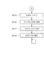
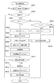
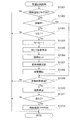
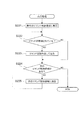
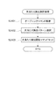
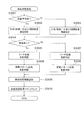
図5−1は、遊技制御部200による基本処理の動作を示すフローチャートである。
遊技制御部200は、パチンコ遊技機100の電源が投入されると、まず、RAM203(図3参照)へのアクセスを許可する(ステップ(以下、ステップを「S」と記載する)101)。そして、遊技制御部200は、RAM203をクリアするためのRAMクリアスイッチがONとなっているか否かを判断する(S102)。
RAMクリアスイッチがOFFである場合(S102でNo)、次に、遊技制御部200は、電源遮断時の動作に関するバックアップフラグがONとなっているか否かを判断する(S103)。
バックアップフラグがONである場合(S103でYes)、次に、遊技制御部200は、電源遮断時に作成されたチェックサムが正常か否かを判断する(S104)。
チェックサムが正常である場合(S104でYes)、次に、遊技制御部200は、復帰処理を実行する(S105)。この復帰処理において、遊技制御部200は、電源が遮断された状態からの復帰に伴う、演出制御部300等のサブ制御手段の設定を行う。具体的には、遊技制御部200は、電源が遮断される際におけるパチンコ遊技機100の遊技状態(大当たり遊技中か否か、高確率状態と低確率状態のいずれか、時短状態と時短無状態のいずれか)を反映させるように、サブ制御手段を設定するためのコマンドを演出制御部300へ出力する。また、この復帰処理において、遊技制御部200は、バックアップフラグをOFFにする。
FIG. 5A is a flowchart illustrating an operation of basic processing by the
When the power of the
If the RAM clear switch is OFF (No in S102), the
If the backup flag is ON (Yes in S103), the
If the checksum is normal (Yes in S104), the
一方、RAMクリアスイッチがON(S102でYes)、バックアップフラグがOFF(S103でNo)、チェックサムが異常(S104でNo)のいずれかに該当する場合、次に遊技制御部200は、初期化処理として、RAM203の記憶内容をクリアし(S106)、RAM203の作業領域を設定する(S107)。そして、遊技制御部200は、サブ制御手段を設定(初期化)するためのコマンドを演出制御部300へ出力し、サブ基板(サブ制御手段)の設定を行う(S108)。サブ基板の設定には、各サブ基板に搭載されているRAM303、RAM313、RAM323をクリアすること等が含まれる。
On the other hand, if the RAM clear switch is ON (Yes in S102), the backup flag is OFF (No in S103), and the checksum is abnormal (No in S104), then the
復帰処理(S105参照)が終了した後、またはサブ基板の設定(S108参照)が終了した後、遊技制御部200は、遊技制御に用いられる各種のカウンタおよびタイマーを設定する(S109)。そして、遊技制御部200は、割り込み許可(S110)、割り込み禁止(S111)、図柄乱数制御処理(S112)、初期値乱数更新処理(S113)、電源遮断フラグがONとなっているか否かの判断(S114)をループ処理として繰り返し実行する。
ここで、割り込み許可(S110)および割り込み禁止(S111)は、このループ処理(S110〜S114)の実行中に割り込み処理の実行を可能とするために設けられている。本実施の形態では、この割り込み処理により、遊技制御における主制御処理が実行される。主制御処理の詳細については後述する。
図柄乱数制御処理(S112)において、遊技制御部200は、特別図柄抽選で用いられる変動パターン乱数の更新を行う。
初期値乱数更新処理(S113)において、遊技制御部200は、遊技制御において用いられる各種の乱数値の初期値を更新する。
電源遮断フラグの判断において、電源遮断フラグがOFFである場合(S114でNo)、パチンコ遊技機100の電源は遮断されず、遊技制御部200は、ループ処理(S110〜S114)と共に割り込みによる主制御処理を繰り返し実行する。一方、電源遮断フラグがONである場合(S114でYes)、遊技制御部200は、パチンコ遊技機100の電源を遮断するための処理(電源遮断時処理)を開始する。
After the return process (see S105) is completed or after the setting of the sub-board (see S108) is finished, the
Here, interrupt permission (S110) and interrupt prohibition (S111) are provided to enable execution of interrupt processing during execution of the loop processing (S110 to S114). In the present embodiment, main control processing in game control is executed by this interrupt processing. Details of the main control process will be described later.
In the symbol random number control process (S112), the
In the initial value random number update process (S113), the
In the determination of the power cut-off flag, when the power cut-off flag is OFF (No in S114), the power of the
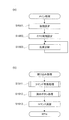
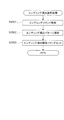
図5−2は、遊技制御部200による電源遮断時処理の動作を示すフローチャートである。
電源遮断時処理において、遊技制御部200は、まず、各種の出力を行うための出力ポートの設定をクリアする(S115)。次に、遊技制御部200は、チェックサムを作成し、RAM203に格納する(S116)。次に、遊技制御部200は、バックアップフラグをONにし(S117)、RAM203へのアクセスを禁止して(S118)、無限ループに移行する。
FIG. 5B is a flowchart illustrating the operation of power-off processing by the
In the power-off process, the
〔遊技機の主制御処理〕
次に、パチンコ遊技機100の主制御処理を説明する。
遊技制御部200は、主制御処理において、パチンコ遊技機100における遊技を制御すると共に、サブ制御手段である演出制御部300に対して演出の制御を指示し、払出制御部330に対して賞球の払い出しの制御を指示する。
[Main control processing of gaming machines]
Next, main control processing of the
In the main control process, the
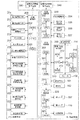
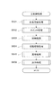
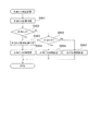
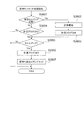
図5−3は、遊技制御部200の主制御処理を示すフローチャートである。
主制御処理は、遊技制御における一連の処理からなり、予め設定された一定時間(例えば4ミリ秒)ごとに繰り返し実行される。本実施の形態において、遊技制御部200は、予め設定された一定時間ごとに割り込みを発生させ、図5−1に示すループ処理の中で割り込みが許可(S110参照)されると、割り込み処理として主制御処理を実行する。図5−3に示すように、主制御処理では、乱数更新処理、スイッチ処理、図柄処理、電動役物処理、賞球処理、出力処理が順次実行される(S501〜S506)。
FIG. 5-3 is a flowchart showing main control processing of the
The main control process includes a series of processes in game control, and is repeatedly executed every predetermined time (for example, 4 milliseconds). In the present embodiment, the
乱数更新処理(S501)では、遊技制御部200は、乱数制御部241の機能(サブルーチン)を呼び出し、遊技制御部200による遊技制御で用いられる各種の乱数の値を更新する。乱数の設定および乱数値の更新の詳細については後述する。
In the random number update process (S501), the
スイッチ処理(S502)としては、始動口スイッチ処理、ゲートスイッチ処理が行われる。
始動口スイッチ処理では、遊技制御部200は、乱数取得部231の機能(サブルーチン)を呼び出し、図3の第1始動口スイッチ211および第2始動口スイッチ212の状態を監視し、スイッチがONとなった場合に、特別図柄抽選のための処理を実行する。
ゲートスイッチ処理では、遊技制御部200は、普通図柄判定部232の機能(サブルーチン)を呼び出し、図3のゲートスイッチ214の状態を監視し、スイッチがONとなった場合に、普通図柄抽選のための処理を実行する。
これらのスイッチ処理の詳細な内容については後述する。
As the switch process (S502), a start port switch process and a gate switch process are performed.
In the start port switch process, the
In the gate switch process, the
The detailed contents of these switch processes will be described later.
図柄処理(S503)としては、特別図柄処理、普通図柄処理が行われる。
特別図柄処理では、遊技制御部200は、特別図柄変動制御部233、特別図柄判定部234、変動パターン選択部235の各機能(サブルーチン)を呼び出し、特別図柄変動およびこの図柄変動に伴う処理を実行する。
普通図柄処理では、遊技制御部200は、普通図柄変動制御部236の機能(サブルーチン)を呼び出し、普通図柄変動およびこの図柄変動に伴う処理を実行する。
これらの図柄処理の詳細な内容については後述する。
As the symbol processing (S503), special symbol processing and normal symbol processing are performed.
In the special symbol process, the
In the normal symbol process, the
The detailed contents of these symbol processes will be described later.
電動役物処理(S504)としては、大入賞口処理、電動チューリップ処理が行われる。
大入賞口処理では、遊技制御部200は、大入賞口動作制御部237の機能(サブルーチン)を呼び出し、所定の条件に基づいて大入賞口125の開放動作を制御する。
電動チューリップ処理では、遊技制御部200は、電動チューリップ動作制御部238の機能(サブルーチン)を呼び出し、所定の条件に基づいて電動チューリップ123の開放動作を制御する。
これらの電動役物処理の詳細な内容については後述する。
As the electric accessory process (S504), a big prize opening process and an electric tulip process are performed.
In the special prize opening process, the
In the electric tulip process, the
Detailed contents of these electric accessory processing will be described later.
賞球処理(S505)では、遊技制御部200は、賞球処理部239の機能(サブルーチン)を呼び出し、入賞個数の管理および入賞に応じた賞球の払い出しの制御用コマンドをセットする。
In the winning ball process (S505), the
出力処理(S506)では、遊技制御部200は、出力制御部240の機能(サブルーチン)を呼び出し、演出制御用のコマンドを演出制御部300へ出力し、払い出し制御用のコマンドを払出制御部330へ出力する。演出制御用コマンドは、S502からS504までの各処理において生成され、RAM203に設けられた制御用コマンドの格納領域に格納(セット)される。払い出し制御用コマンドは、S505の処理において生成され、RAM203に設けられた制御用コマンドの格納領域に格納(セット)される。RAM203には、制御用コマンドの種類ごとに格納領域が設定されている。
In the output process (S506), the
出力制御部240は、RAM203の各制御用コマンドの格納領域を順に調べ、個々の格納領域に制御用コマンドが格納されていれば(すなわち、S502〜S505の処理で制御用コマンドが生成されていれば)、その制御用コマンドを読み出し、出力先(演出制御部300または払出制御部330)へ出力する。
The
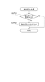
本実施の形態では、図5−3に示したように、一連の主制御処理の最後に出力処理を行う。すなわち、第1の処理手段としての上記各機能によるS502〜S505の各処理において生成されたコマンドを、その各処理においてはRAM203の対応する格納領域に格納しておく。そして、これらの処理の後に、第2の処理手段としての出力制御部240が、RAM203の格納領域に蓄積された、各処理で生成されたコマンドをまとめて出力する。言い換えれば、本実施の形態では、主制御処理を1サイクル実行すると、その1サイクルの実行において生成されたコマンドが、その1サイクルの実行における最後のコマンド生成が行われた後に、出力される。
In the present embodiment, as shown in FIG. 5C, output processing is performed at the end of a series of main control processing. That is, the command generated in each process of S502 to S505 by the above functions as the first processing means is stored in a corresponding storage area of the
〔遊技機の基本動作の変形例〕
なお、図5−1乃至図5−3を参照して説明した動作例では、基本処理におけるループ処理の部分で割り込みを許可し、割り込み処理として一連の処理からなる主制御処理を実行した。しかしながら、主制御処理は、一定時間ごとに繰り返し実行されるように構成されていれば良く、具体的な実現手段(実行手順)は、図5−1乃至図5−3に示した例には限定されない。例えば、基本処理の一連の動作の中に主制御処理を組み入れておき、所定のタイミングで経過時間を計測し、一定時間(例えば4ミリ秒)ごとに主制御処理へ戻る構成としても良い。また、基本処理の一連の動作の中に主制御処理を組み入れる一方で、図5−1乃至図5−3を参照して説明した動作と同様に、一定時間ごとに割り込みを発生させ、割り込みが発生したならば基本処理中に組み入れられた主制御処理へ戻る構成としても良い。
[Modified example of basic operation of gaming machine]
In the operation example described with reference to FIGS. 5A to 5C, the interrupt is permitted in the loop process portion of the basic process, and the main control process including a series of processes is executed as the interrupt process. However, the main control process only needs to be configured to be repeatedly executed at regular intervals, and specific implementation means (execution procedure) is not limited to the examples shown in FIGS. It is not limited. For example, the main control process may be incorporated in a series of operations of the basic process, the elapsed time may be measured at a predetermined timing, and the process may return to the main control process every certain time (for example, 4 milliseconds). In addition, while incorporating the main control process in the series of operations of the basic process, as in the operation described with reference to FIG. 5A to FIG. If it occurs, it may be configured to return to the main control process incorporated in the basic process.
また、基本処理で生成されたコマンドを出力する場合は、原則として、コマンドを生成する度に、RAM203のコマンド格納領域に格納し、第2の処理手段である出力制御部240の機能を呼び出して出力する。基本処理は、遊技の進行に関わる主制御処理とは異なり、電源投入時にのみ行われる初期動作等の特別な処理である。また、基本処理は、電源投入時のパチンコ遊技機100の状態等の条件に基づく分岐により処理手順が変動する場合があるため、出力処理に漏れが無いように、生成したコマンドを速やかに出力する処理である。なお、関連する複数の処理により連続的にコマンドが生成される場合等、具体的な処理の要請に応じて、複数のコマンドをRAM203のコマンド格納領域に格納し、まとめて出力する処理手順を採っても良い。
When a command generated by basic processing is output, in principle, every time a command is generated, the command is stored in the command storage area of the
〔遊技制御部での始動口スイッチ処理〕
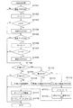
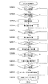
図6は、図5−3のS502に示したスイッチ処理のうちの始動口スイッチ処理の内容を示すフローチャートである。
この始動口スイッチ処理は、第1始動口121における入賞に対する処理と、第2始動口122における入賞に対する処理とが順次行われる。図6を参照すると、遊技制御部200は、まず、第1始動口121に遊技球が入賞して第1始動口スイッチ211がONとなったか否かを判断する(S601)。第1始動口スイッチ211がONとなったならば、次に遊技制御部200は、第1始動口121の入賞における未変動分の保留数U1が上限値未満か否かを判断する(S602)。図6に示す例では、上限値を4個としている。保留数U1が上限値に達している場合は(S602でNo)、それ以上未変動分の入賞を保留することができないので、第1始動口121における入賞に対する処理を終了する。
[Start-up switch processing in game control unit]
FIG. 6 is a flowchart showing the contents of the start port switch process in the switch process shown in S502 of FIG. 5-3.
In the start port switch process, a process for winning at the
一方、保留数U1が上限値未満である場合(S602でYes)、遊技制御部200の乱数取得部231は、今回の入賞による判定のための乱数値を取得し、RAM203に格納する(S603)。ここでは、第1始動口121の入賞なので、特別図柄抽選のための乱数値が取得される。このとき取得される乱数値は、S501の乱数更新処理で更新された値である。そして、この乱数値により、後の特別図柄処理において特別図柄抽選の結果が確定される。ここにいう乱数値としては、大当たり、小当たりまたははずれを決定する大当たり乱数値、大当たりの種類(大当たり遊技の終了後における時短状態か時短無状態、高確率状態と低確率状態、長当たり、短当たり)を決定する図柄乱数値(大当たり図柄乱数値)、図柄変動における変動パターンを特定するための変動パターン乱数値、はずれのときにリーチ有り演出をするか否かを決定するリーチ乱数値、等が含まれる。
そして、遊技制御部200は、保留数U1の値を1加算する(S604)。
On the other hand, when the hold number U1 is less than the upper limit value (Yes in S602), the random
Then, the
次に、遊技制御部200は、事前判定処理を行う(S605)。
ここで、事前判定処理とは、始動口における入賞により乱数の取得が既に行われているが後述する特別図柄処理によって乱数の判定が未だ行われていない入賞球(保留球)について、特別図柄処理によって乱数が判定されるよりも以前にその乱数の判定を行う(事前判定)処理である。
Next, the
Here, the pre-determination process is a special symbol process for a winning ball (holding ball) for which a random number has already been acquired by winning at the start opening, but has not yet been determined by a special symbol process described later. The random number is determined before the random number is determined by (preliminary determination).
そして、本実施の形態の演出制御部300は、後述するように、事前判定処理によって判定された乱数の判定結果(事前判定結果)に基づいて、特別図柄処理によって乱数が判定され、その判定結果(抽選結果)が報知されるよりも以前に、その判定結果を示唆する予告演出を行うことができる。
事前判定に基づく予告演出として、例えば保留表示において行う例を挙げることができる。本実施の形態では、後述するように、始動口における入賞により乱数の取得が既に行われているが、後述する特別図柄処理によって乱数の判定が未だ行われていない入賞球(保留球)については画像表示部114において保留表示が行われる。そして、この保留表示に事前判定結果を反映させ、その保留球に関して、その後に特別図柄処理による乱数の判定が行われた際の判定結果を遊技者に示唆する。これによって、遊技者は、保留球に対して期待を抱きながら遊技を行うことができる。
なお、事前判定結果を用いた予告演出は、保留表示に限らず、特別図柄処理による乱数の判定結果(抽選結果)が報知されるよりも以前に行われる各種の演出内容に反映させることで、多様な予告演出を行うことが可能になる。
And the production | generation control part 300 of this Embodiment determines a random number by a special symbol process based on the determination result (predetermined result) of the random number determined by the prior determination process so that it may mention later, The determination result Before the (lottery result) is notified, a notice effect that suggests the determination result can be performed.
As a notice effect based on prior determination, for example, an example can be given in a hold display. In the present embodiment, as will be described later, random numbers have already been acquired by winning at the start opening, but for the winning balls (holding balls) for which random number determination has not yet been performed by special symbol processing described later. The
In addition, the notice effect using the pre-determined result is not limited to the hold display, but by reflecting it in various effect contents performed before the determination result (lottery result) of the random number by special symbol processing is notified, It becomes possible to perform various notice effects.
この後、遊技制御部200は、事前判定結果を演出制御部300に通知するために、S605の事前判定処理による事前判定情報を含む事前判定結果コマンドをRAM203にセットする(S606)。
さらに、遊技制御部200は、S604による保留数U1の増加を演出制御部300に通知するための保留数増加コマンドをRAM203にセットし(S607)、第1始動口121における入賞に対する処理を終了する。
Thereafter, the
Further, the
次に、第2始動口122における入賞に対する処理が行われる。図6を参照すると、次に遊技制御部200は、第2始動口122に遊技球が入賞して第2始動口スイッチ212がONとなったか否かを判断する(S608)。第2始動口スイッチ212がONとなったならば、次に、遊技制御部200は、第2始動口122の入賞における未変動分の保留数U2が上限値未満か否かを判断する(S609)。図6に示す例では、上限値を4個としている。保留数U2が上限値に達している場合は(S609でNo)、それ以上未変動分の入賞を保留することができないので、第2始動口122における入賞に対する処理を終了する。
Next, a process for winning in the
一方、保留数U2が上限値未満である場合(S609でYes)、遊技制御部200の乱数取得部231は、今回の入賞による抽選のための乱数値を取得し、RAM203に格納する(S610)。ここでは、第2始動口122の入賞なので、上記のS603と同様に、特別図柄抽選のための乱数値(大当たり乱数値、大当たり図柄乱数値)、リーチ乱数値、変動パターン乱数値など)が取得される。このとき取得される乱数値は、S501の乱数更新処理で更新された値である。そして、この乱数値により後の特別図柄処理において特別図柄抽選の結果が確定される。
そして、遊技制御部200は、保留数U2の値を1加算する(S611)。
On the other hand, when the hold number U2 is less than the upper limit value (Yes in S609), the random
Then, the
次に、遊技制御部200は、事前判定処理を行う(S612)。この事前判定処理の内容は、上記のS605と同様である。
この後、遊技制御部200は、事前判定結果を演出制御部300に通知するために、S612の事前判定処理による事前判定情報を含む事前判定結果コマンドをRAM203にセットする(S613)。
さらに、遊技制御部200は、S611による保留数U2の増加を演出制御部300に通知するための保留数増加コマンドをRAM203にセットし(S614)、第2始動口122における入賞に対する処理を終了する。
Next, the
Thereafter, the
Furthermore, the
〔遊技制御部でのゲートスイッチ処理〕
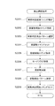
図7は、ゲート124を遊技球が通過した場合のゲートスイッチ処理の内容を示すフローチャートである。
このゲートスイッチ処理において、遊技制御部200は、まず、ゲート124を遊技球が通過してゲートスイッチ214がONとなったか否かを判断する(S701)。ゲートスイッチ214がONとなったならば、次に遊技制御部200は、未変動分の保留数Gが上限値未満か否かを判断する(S702)。図7に示す例では、上限値を4個としている。保留数Gが上限値に達している場合は(S702でNo)、それ以上未変動分の入賞を保留することができないので、ゲートスイッチ処理を終了する。
[Gate switch processing in game control unit]
FIG. 7 is a flowchart showing the contents of the gate switch process when a game ball passes through the gate 124.
In this gate switch process, the
一方、保留数Gが上限値未満である場合(S702でYes)、遊技制御部200は、遊技制御部200の乱数取得部231は、今回の入賞による抽選のための乱数値を取得し、RAM203に格納する(S703)。ここでは、ゲート124の入賞なので、普通図柄抽選のための乱数値(当たり乱数値など)が取得される。
On the other hand, when the number of holdings G is less than the upper limit value (Yes in S702), the
次に、遊技制御部200は、保留数Gの値を1加算する(S704)。
S704で保留数Gの値が加算された後、遊技制御部200は、S704による保留数Gの増加を演出制御部300に通知するための保留数G増加コマンドをRAM203にセットし(S705)、ゲート124における入賞に対する処理を終了する。
Next, the
After the value of the hold number G is added in S704, the
〔遊技制御部での特別図柄処理〕
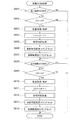
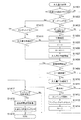
図8は、図5−3のS503に示した図柄処理のうちの特別図柄処理の内容を示すフローチャートである。
この特別図柄処理において、遊技制御部200の特別図柄変動制御部233は、まず、RAM203においてセットされるフラグの設定(以下、フラグ設定)において大当たり遊技フラグがONになっているか否かを調べる(S801)。ここで、大当たり遊技フラグは、特別図柄抽選の結果が大当たりであることを識別するためにセットされるフラグである。大当たりの種類に応じて、長当たり遊技フラグ、短当たり遊技フラグの何れかがセットされる。本実施の形態では、これらを総称して大当たり遊技フラグと呼ぶ。
[Special symbol processing in game control unit]
FIG. 8 is a flowchart showing the contents of the special symbol processing in the symbol processing shown in S503 of FIG. 5-3.
In this special symbol process, the special symbol
大当たり遊技フラグがONである場合、既にパチンコ遊技機100は大当たり中であるので、特別図柄変動を開始することなく特別図柄処理を終了する(S801でYes)。一方、大当たり遊技フラグがOFFである場合(S801でNo)、次に特別図柄変動制御部233は、パチンコ遊技機100の現在の状態が特別図柄変動中か否かを判断する(S802)。特別図柄変動中でない場合(S802でNo)、次に特別図柄変動制御部233は、特別図柄の未変動分の保留数U1、U2(図6参照)に関する処理を行う(S803〜S806)。本実施の形態では、第1始動口121の入賞に係る保留数U1と第2始動口122の入賞に係る保留数U2とを区別しているので、この処理も対応する始動口ごとに個別に行う。
If the jackpot gaming flag is ON, the
具体的には、特別図柄変動制御部233は、まず第2始動口122の入賞に係る保留数U2が1以上か判断する(S803)。保留数U2が1以上である場合(S803でYes)、特別図柄変動制御部233は、保留数U2の値を1減算する(S804)。一方、保留数U2=0である場合は(S803でNo)、特別図柄変動制御部233は、次に第1始動口121の入賞に係る保留数U1が1以上か判断する(S805)。保留数U1が1以上である場合(S805でYes)、特別図柄変動制御部233は、保留数U1の値を1減算する(S806)。一方、保留数U1=0である場合は(S805でNo)、特別図柄の抽選を始動するための入賞が無いことを意味するため、特別図柄変動を開始せず、別ルーチンの客待ち設定処理を実行して処理を終了する(S816)。
Specifically, the special symbol
S804またはS806で保留数U1または保留数U2を減算した後、特別図柄変動制御部233は、RAM203のフラグ設定においてセットされた客待ちフラグをOFFとする(S807)。客待ちフラグは、パチンコ遊技機100が客待ち状態であることを識別するためのフラグであり、客待ち設定処理(S816、図12参照)においてセットされる。
After subtracting the reserved number U1 or the reserved number U2 in S804 or S806, the special symbol
次に、特別図柄変動制御部233は、別ルーチンによる大当たり判定処理および変動パターン選択処理を実行する(S808、S809)。詳しくは後述するが、この大当たり判定処理および変動パターン選択処理によって、第1特別図柄表示器221に変動表示される特別図柄の変動用の設定情報(大当たり図柄、遊技状態、変動パターン等)が決定される。なお、これらの情報は演出制御部300に送られる変動開始コマンドに含まれる。
Next, the special symbol
この後、特別図柄変動制御部233は、大当たり判定処理および変動パターン選択処理で決定された設定内容に基づき、図2に示す第1特別図柄表示器221、第2特別図柄表示器222により表示される特別図柄の変動を開始する(S810)。そして、この設定内容を示す設定情報(大当たり図柄、遊技状態、変動パターン等)を含んだ変動開始コマンドを生成し、RAM203にセットする(S811)。S811でセットされた変動開始コマンドは、図5−3のS506に示した出力処理で演出制御部300へ送信される。
Thereafter, the special symbol
S802で特別図柄変動中と判断された場合(S802でYes)、またはS811で変動開始コマンドがセットされた後、特別図柄変動制御部233は、変動時間を経過したか否かを判断する(S812)。すなわち、S810で特別図柄の変動を開始してからの経過時間がS809の変動パターン選択処理で設定された変動時間に達したか否かが判断される。変動時間を経過していなければ(S812でNo)、特別図柄変動が継続されるので、そのまま特別図柄処理が終了する。
When it is determined in S802 that the special symbol is changing (Yes in S802), or after the change start command is set in S811, the special symbol
一方、変動時間を経過した場合(S812でYes)、特別図柄変動制御部233は、まず、第1特別図柄表示器221、第2特別図柄表示器222における特別図柄の変動をS808の大当たり判定処理で決定された図柄で停止する(S813)。後述する装飾図柄を停止させるための変動停止コマンドをRAM203にセットする(S814)。そして、別ルーチンの停止中処理を実行する(S815)。停止中処理の内容については後述する。S814でセットされた変動停止コマンドは、図5−3のS506に示した出力処理で演出制御部300へ送信される。
On the other hand, when the variation time has elapsed (Yes in S812), the special symbol
〔遊技制御部による大当たり判定処理〕
図9は、大当たり判定処理(図8のS808)の内容を示すフローチャートである。
この大当たり判定処理において、遊技制御部200の特別図柄判定部234は、まず、今回の特別図柄抽選における大当たり乱数値の判定を行い(S901)、大当たりまたは小当たりしたか否かを判断する(S902、S905)。大当たりまたは小当たりしたか否かは、図6のS603またはS610で取得した大当たり乱数の値が、大当たりの当選値として設定された値または小当たりの当選値として設定された値と一致したか否かを判断することによって決定される(図17(a)参照)。
[Big hit judgment processing by game control unit]
FIG. 9 is a flowchart showing the contents of the jackpot determination process (S808 in FIG. 8).
In this jackpot determination process, the special
S901の乱数判定の結果が大当たりだった場合(S902でYes)、次に特別図柄判定部234は、大当たり図柄乱数値の判定を行う(S903)。この判定の結果に応じて、大当たりの種類(高確率状態か低確率状態、時短状態か時短無状態、長当たり、短当たり)が決定される。何れの大当たりとなるかは、図6のS603またはS610で取得した大当たり図柄乱数の値が、大当たりの種類ごとに予め設定された値のうちの何れと一致したかによって決定される(図17(b)参照)。
If the result of the random number determination in S901 is a big hit (Yes in S902), then the special
以上の判定の後、特別図柄判定部234は、大当たり図柄乱数の判定により決定された大当たりの種類を表す図柄(大当たり図柄)を設定情報としてRAM203にセットする(S904)。
After the above determination, the special
S901の乱数判定の結果が小当たりだった場合(S902でNo、S905でYes)、次に特別図柄判定部234は、小当たりであることを表す図柄(以下、小当たり図柄)を設定情報としてRAM203にセットする(S906)。
If the result of the random number determination in S901 is a small hit (No in S902, Yes in S905), then the special
S901の乱数判定の結果が大当たりでも小当たりでもない場合(S902、S905でNo)、次に特別図柄判定部234は、抽選にはずれたことを表す図柄(以下、はずれ図柄)を設定情報としてRAM203にセットする(S907)。
If the result of the random number determination in S901 is neither big win nor small win (No in S902 and S905), then the special
〔遊技制御部による変動パターン選択処理〕
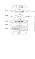
図10は、変動パターン選択処理(図8のS809)の内容を示すフローチャートである。
この変動パターン選択処理において、遊技制御部200の変動パターン選択部235は、まず、パチンコ遊技機100の遊技状態(時短無状態か時短状態か、および高確率状態か低確率状態か)を参照する(S1001)。そして、大当たり判定処理(図9)のS902の判断結果を用いて今回の特別図柄抽選で大当たりしたか否かを判断する(S1002)。そして、大当たりだった場合(S1002でYes)、変動パターン選択部235は、大当たり用の変動パターンテーブルをROM202から読み出してRAM203にセットする(S1003)。
[Change pattern selection process by game control unit]
FIG. 10 is a flowchart showing the contents of the variation pattern selection process (S809 in FIG. 8).
In this variation pattern selection process, the variation
一方、大当たりしなかった場合(S1002でNo)、次に変動パターン選択部235は、遊技者に大当たりを期待させるためのいわゆるリーチ演出を行うか否かを決定するための乱数値の判定を行う(S1004)。リーチ演出を行うか否かは、図6のS603またはS610で取得したリーチ乱数の値が予め設定された値と一致したか否かを判断することによって決定される(図17(c)参照)。
乱数値を用いた判定の結果、リーチ演出を行う場合(S1005でYes)、変動パターン選択部235は、リーチ用の変動パターンテーブルをROM202から読み出してRAM203にセットする(S1006)。また、リーチ演出を行わない場合(S1005でNo)、変動パターン選択部235は、はずれ用の変動パターンテーブルをROM202から読み出してRAM203にセットする(S1007)。
ここで、変動パターンテーブルとは、予め用意されている複数の変動パターン(変動時間3秒、7秒、13秒、15秒、30秒、60秒、90秒など)と変動パターン乱数の値とを対応付けたテーブルである。
On the other hand, if the jackpot has not been won (No in S1002), the variation
As a result of the determination using the random number value, when the reach effect is performed (Yes in S1005), the variation
Here, the fluctuation pattern table includes a plurality of fluctuation patterns prepared in advance (
次に、変動パターン選択部235は、図6のS603またはS610で取得した変動パターン乱数値およびS1003、S1006、S1007でセットされた変動パターンテーブルを用いて、変動パターン乱数値の判定を行う(S1008)。すなわち、変動パターン選択部235は、RAM203にセットされた変動パターンテーブルを参照し、変動パターン乱数の乱数値に応じた変動パターンを選択する。したがって、同じ乱数値が取得された場合でも、パチンコ遊技機100の遊技状態(時短状態か時短無し状態か、および高確率状態か低確率状態か)、特別図柄抽選の結果(大当たりしたか否か、大当たりしていない場合はリーチ演出を行うか否か等、の違いに応じて参照される変動パターンテーブルが異なるので、決定される変動パターンが異なる。
Next, the variation
この後、変動パターン選択部235は、S1008で選択した変動パターンを設定情報としてRAM203にセットする(S1009)。S1009でセットされた変動パターンの設定情報は、図8のS811でセットされる変動開始コマンドに含まれ、図5−3のS506に示した出力処理で演出制御部300へ送信される。本実施の形態で選択される変動パターンおよびその設定の詳細については後述する。
Thereafter, the fluctuation
〔遊技制御部による停止中処理〕
図11は、停止中処理(図8のS815)の内容を示すフローチャートである。
この停止中処理において、遊技制御部200は、まず、RAM203のフラグ設定において時短状態であることを示すフラグ(以下、時短フラグ)がONになっているか否かを調べる(S1101)。時短フラグがONである場合(S1101でYes)、遊技制御部200は、時短状態での抽選回数(変動回数)Jの値を1減算し(S1102)、抽選回数Jが0になったか否かを調べる(S1103)。そして、抽選回数J=0であれば(S1103でYes)、時短フラグをOFFにする(S1104)。なお、時短フラグをONにする操作と、抽選回数Jの初期値の設定は、後述の大入賞口処理(図14)における遊技状態設定処理(図15)で行われる。
[Processing during stop by game control unit]
FIG. 11 is a flowchart showing the contents of the suspension process (S815 in FIG. 8).
In the stop process, the
時短フラグがOFFであった場合(S1101でNo)またはS1104で時短フラグをOFFにした後、あるいは抽選回数Jの値が0でない場合(S1103でNo)、次に遊技制御部200は、RAM203のフラグ設定において高確率状態であることを示すフラグ(以下、確変フラグ)がONになっているか否かを調べる(S1105)。なお、この確変フラグと先の時短フラグが共にONである場合は、高確率時短遊技状態であり、確変フラグがONであり時短フラグがOFFである場合は、高確率時短無遊技状態である。
If the time reduction flag is OFF (No in S1101), or after the time reduction flag is turned OFF in S1104, or if the value of the lottery count J is not 0 (No in S1103), the
確変フラグがONである場合(S1105でYes)、遊技制御部200は、高確率状態での抽選回数(変動回数)Xの値を1減算し(S1106)、抽選回数Xが0になったか否かを調べる(S1107)。そして、抽選回数X=0であれば(S1107でYes)、確変フラグをOFFにする(S1108)。なお、確変フラグをONにする操作と、抽選回数Xの初期値の設定は、後述の大入賞口処理(図14)における遊技状態設定処理(図15)で行われる。
When the probability variation flag is ON (Yes in S1105), the
確変フラグがOFFであった場合(S1105でNo)またはS1108で確変フラグをOFFにした後、あるいは抽選回数Xの値が0でない場合(S1107でNo)、次に遊技制御部200は、今回の特別図柄抽選で大当たりしたか否かを判断する(S1109)。そして、大当たりだった場合(S1109でYes)、次に遊技制御部200は、大当たりの種類が長当たりか否かを判断する(S1110)。
If the probability change flag is OFF (No in S1105), or after the probability change flag is turned OFF in S1108, or if the value of the lottery count X is not 0 (No in S1107), the
ここで、大当たりか否かの判断は、大当たり判定処理(図9)の判定結果に基づいて判断することができる。例えば、後述する図17(b)の図表に示す図柄の何れかがセットされているならば、S1109でYesである。大当たり判定処理によりRAM203に、はずれ図柄または小当たり図柄がセットされているならば、S1109でNoである。
Here, the determination of whether or not the jackpot is possible can be made based on the determination result of the jackpot determination process (FIG. 9). For example, if any of the symbols shown in the diagram of FIG. 17B to be described later is set, “Yes” is determined in S1109. If a lost symbol or a small bonus symbol is set in the
大当たりの種類が長当たりであった場合(S1110でYes)、遊技制御部200は、長当たり遊技フラグをONにする(S1111)。これにより、RAM203の遊技状態の設定が、大当たりの種類が長当たりである大当たり遊技状態(長当たり遊技状態)となる。なお、ここでは長当たりにおいて、高確率状態か低確率状態かを区別していない。高確率状態となるか低確率状態となるかは、後述の大入賞口処理(図14)における遊技状態設定処理(図15)で該当するフラグをONにすることによって特定される。
When the jackpot type is a long hit (Yes in S1110), the
大当たりの種類が長当たりでなかった場合(S1110でNo)、遊技制御部200は、短当たり遊技フラグをONにする(S1112)。これにより、RAM203の遊技状態の設定が、大当たりの種類が短当たりである大当たり遊技状態(短当たり遊技状態)となる。長当たりの場合と同様、短当たりの場合も高確率状態か低確率状態かを区別していない。
If the jackpot type is not long hit (No in S1110), the
S1111またはS1112で大当たり遊技フラグをONにした後、遊技制御部200は、抽選回数J、Xの値を初期化する(S1113)。また、遊技制御部200は、S1101において時短フラグがONであって、S1103において抽選回数Jが0でなかった場合に、時短フラグをOFFにする(S1114)。同様に、S1105において確変フラグがONであって、S1107において抽選回数Xが0でなかった場合に、確変フラグをOFFにする(S1114)。
After turning on the jackpot game flag in S1111 or S1112, the
一方、今回の特別図柄抽選の結果が大当たりでなかった場合(S1109でNo)、次に遊技制御部200は、今回の特別図柄抽選の結果が小当たりであったか否かを判断する(S1115)。小当たりでなかった場合は(S1115でNo)、停止中処理を終了する。
一方、小当たりであった場合(S1115でYes)、遊技制御部200は、小当たり遊技を開始する(S1116)。これにより、RAM203の遊技状態の設定が小当たり遊技状態となる。なお、小当たり遊技では、前述したように、大入賞口125を所定回数開閉し、所定時間経過後に終了する。
On the other hand, when the result of the special symbol lottery this time is not a big hit (No in S1109), the
On the other hand, when it is a small hit (Yes in S1115), the
S1113で抽選回数J、Xの値を初期化した後、遊技制御部200は、オープニング動作を開始する(S1117)。ここで、オープニング動作の内容は、S1111、S1112の何れで当たり遊技フラグがONとなったかに応じて異なる。すなわち、大当たり遊技フラグの状態に応じて、長当たり遊技、短当たり遊技の各遊技状態において設定されたオープニング動作の何れかが行われることとなる。
この後、遊技制御部200は、演出制御部300において大当たり遊技フラグに応じたオープニング動作における演出を行うためのオープニングコマンドをRAM203にセットして(S1118)、停止中処理を終了する。このオープニングコマンドは、図5−3のS506に示した出力処理で演出制御部300へ送信される。
After initializing the values of the lottery times J and X in S1113, the
After that, the
〔遊技制御部による客待ち設定処理〕
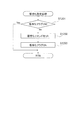
図12は、客待ち設定処理(図8のS816)の内容を示すフローチャートである。
この客待ち設定処理において、遊技制御部200は、まず、RAM203のフラグ設定において客待ちフラグがONになっているか否かを調べる(S1201)。ここで、客待ちフラグは、パチンコ遊技機100が客待ち状態であることを識別するためにセットされるフラグである。
[Customer waiting setting process by game control unit]
FIG. 12 is a flowchart showing the contents of the customer waiting setting process (S816 in FIG. 8).
In this customer waiting setting process, the
客待ちフラグがONである場合、パチンコ遊技機100は客待ち状態であるので、そのまま処理を終了する(S1201でYes)。一方、客待ちフラグがOFFである場合、遊技制御部200は、客待ちコマンドを生成してRAM203にセットし(S1202)、客待ちフラグをONにする(S1203)。S1202でセットされた客待ちコマンドは、図5−3のS506に示した出力処理で演出制御部300へ送信される。なお、客待ちフラグとは、特別図柄の変動が停止して、保留が無い状態でセットされるものである。
If the customer waiting flag is ON, the
〔遊技制御部による普通図柄処理〕
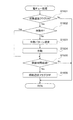
図13は、図5−3のS503に示した図柄処理のうちの普通図柄処理の内容を示すフローチャートである。
この普通図柄処理において、遊技制御部200の普通図柄変動制御部236は、まず、RAM203のフラグ設定において補助遊技フラグがONになっているか否かを調べる(S1301)。ここで、補助遊技フラグは、普通図柄抽選で当選した場合にセットされるフラグである。補助遊技フラグが設定されている状態は、電動チューリップ123が後述の電動チューリップ処理(図16)にしたがって開放され、第2始動口122に入賞し易い状態である(補助遊技状態)。
[Normal symbol processing by game control unit]
FIG. 13 is a flowchart showing the contents of the normal symbol processing in the symbol processing shown in S503 of FIG. 5-3.
In this normal symbol process, the normal symbol
補助遊技フラグがONである場合、既に補助遊技状態となっており、普通図柄が停止している状態なので、普通図柄変動を開始することなく普通図柄処理を終了する(S1301でYes)。一方、補助遊技フラグがOFFである場合(S1301でNo)、次に普通図柄変動制御部236は、パチンコ遊技機100の現在の状態が普通図柄変動中か否かを判断する(S1302)。普通図柄変動中でない場合(S1302でNo)、次に普通図柄変動制御部236は、普通図柄の未変動分の保留数G(図7参照)が1以上か判断する(S1303)。保留数G=0である場合は(S1303でNo)、普通図柄の抽選を始動するための入賞が無いことを意味するため、普通図柄変動を開始せずに処理を終了する。
When the auxiliary game flag is ON, since the auxiliary game state has already been reached and the normal symbol is stopped, the normal symbol process is terminated without starting the normal symbol variation (Yes in S1301). On the other hand, if the auxiliary game flag is OFF (No in S1301), then the normal symbol
これに対し、保留数Gが1以上である場合(S1303でYes)、普通図柄変動制御部236は、保留数Gの値を1減算し(S1304)、今回の普通図柄抽選における当たり乱数の判定を行って、普通図柄抽選に当選したか否かを判断する(S1305)。当選したか否かは、図7のS703で取得した当たり乱数の値が、後述する図17(d)に示すテーブル等において当選値として設定された値と一致したか否かを判断することによって決定される。
On the other hand, when the reserved number G is 1 or more (Yes in S1303), the normal symbol
次に、普通図柄変動制御部236は、普通図柄抽選の結果に応じて普通図柄の設定を行う(S1306)。すなわち、普通図柄抽選に当選した場合は、当選したことを表す図柄(以下、当たり図柄)を設定情報としてRAM203にセットする。一方、普通図柄抽選に当選しなかった場合は、抽選にはずれたことを表す図柄(以下、はずれ図柄)を設定情報としてRAM203にセットする。
Next, the normal symbol
次に、普通図柄変動制御部236は、普通図柄の変動時間の設定を行う(S1307)。この変動時間は、図11におけるS1104、S1114、後述の図15におけるS1504、S1507等の処理で設定される時短フラグに基づいて設定される。すなわち、S1307による設定の際に時短フラグがONである場合は、短時間(例えば1.5秒)に設定され、時短フラグがOFFである場合は、長時間(例えば4.0秒)に設定される。この設定の後、普通図柄変動制御部236は、S1307の設定内容に基づき、図2(a)および図3に示す普通図柄表示器223における普通図柄の変動を開始する(S1308)。
Next, the normal symbol
S1308で普通図柄の変動を開始した後、またはS1302で普通図柄変動中と判断された場合(S1302でYes)、普通図柄変動制御部236は、変動時間を経過したか否かを判断する(S1309)。すなわち、S1308で普通図柄の変動を開始してからの経過時間がS1307で設定された変動時間に達したか否かが判断される。変動時間を経過していなければ(S1309でNo)、普通図柄変動が継続されるので、そのまま普通図柄処理が終了する。
After starting the change of the normal symbol in S1308 or when it is determined that the normal symbol is changing in S1302 (Yes in S1302), the normal symbol
一方、変動時間が終了した場合(S1309でYes)、普通図柄変動制御部236は、普通図柄表示器223における普通図柄の変動を停止する(S1310)。そして、普通図柄変動制御部236は、停止した普通図柄に基づき普通図柄抽選に当選したか否かを判断する(S1311)。当選したならば(S1311でYes)、補助遊技フラグをONにする(S1312)。一方、抽選にはずれたならば(S1311でNo)、補助遊技フラグをONにすること無く普通図柄処理を終了する。
On the other hand, when the fluctuation time is over (Yes in S1309), the normal symbol
〔遊技制御部による大入賞口処理〕
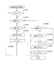
図14は、図5−3のS504に示した電動役物処理のうちの大入賞口処理の内容を示すフローチャートである。
この大入賞口処理において、遊技制御部200の大入賞口動作制御部237は、まず、RAM203のフラグ設定において大当たり遊技フラグがONになっているか否かを調べる(S1401)。大当たり遊技フラグがOFFである場合、大入賞口125への入賞はないので、大入賞口処理を終了する(S1401でNo)。一方、大当たり遊技フラグがONである場合(S1401でYes)、次に大入賞口動作制御部237は、パチンコ遊技機100が停止中処理(図11)で開始された大当たり時の動作制御におけるオープニング動作の最中か否かを判断する(S1402)。
[Large winning mouth processing by game control unit]
FIG. 14 is a flowchart showing the contents of the big prize opening process in the electric accessory process shown in S504 of FIG. 5-3.
In the big prize opening process, the big prize opening
パチンコ遊技機100がオープニング中である場合(S1402でYes)、次に大入賞口動作制御部237は、予め設定されたオープニング動作が行われるべき時間(オープニング時間)を経過したか否かを判断する(S1403)。オープニング時間を経過していないならば、大入賞口125でのオープニング動作が継続されるので、大入賞口処理を終了する(S1403でNo)。一方、オープニング時間を経過したならば(S1403でYes)、次に大入賞口動作制御部237は、大入賞口125の作動設定を行い(S1404)、入賞個数Cを初期化(C=0)し(S1405)、大入賞口125の作動のラウンド数Rの値を現在の値から1加算して(S1406)、大入賞口125を作動開始(開放)する(S1407)。
When the
S1404の作動設定では、大入賞口125の作動パターンと、その作動パターンで作動させるラウンド数(作動ラウンド数)とが設定される。大入賞口125が作動する場合としては、特別図柄抽選で、長当たりまたは短当たりの大当たりであった場合と、小当たりであった場合がある。作動パターンおよびラウンド数は、これらの当たりの種類に応じて様々に設定される。一例としては、長当たりの場合、例えば、15ラウンド(15R)作動させ、1ラウンドでは29.5秒の開放を1回行う。短当たりの場合、例えば、15ラウンド(15R)作動させ、1ラウンドでは0.1秒の開放を1回行う。小当たりの場合、例えば、1ラウンド(1R)作動させ、この1ラウンドで0.1秒の開放を15回行う。ここで、短当たりでの作動と小当たりでの作動を上記の例で比較すると、共に0.1秒の開放が15回行われることとなる。すなわち、遊技者から見える大入賞口125の動作は、短当たりの場合と小当たりの場合とで同じであり、遊技盤110上の大入賞口125の動作のみから短当たりと小当たりとを区別することはできない。
In the operation setting of S1404, the operation pattern of the special winning
また、別の例としては、長当たりでは、15ラウンド(15R)作動させ、1ラウンドでは29.5秒の開放を1回行い、短当たりでは、2ラウンド(2R)作動させ、1ラウンドでは0.9秒の開放を2回行い、小当たりでは、1ラウンド(1R)作動させ、この1ラウンドで0.9秒の開放を2回行う。この場合も、短当たりでの作動と小当たりでの作動を比較すると、共に0.9秒の開放が2回行われることとなり、遊技者から見える大入賞口125の動作は、短当たりの場合と小当たりの場合とで同様となる。
As another example, 15 rounds (15R) are activated per long, 29.5 seconds are released once per round, 2 rounds (2R) are activated per short, and 0 are rounded per round. .9 seconds are opened twice, and with a small hit, one round (1R) is operated, and 0.9 seconds is opened twice in this round. In this case as well, when the operation with short hits and the operation with small hits are compared, both 0.9 seconds are released twice, and the action of the
なお、小当たりの際には、大入賞口125の開放累積時間が1.8秒以内に設定されなければならないことが法令により定められている。一方で、大当たり(長当たりまたは短当たり)の際には、大入賞口125を複数回連続開放させなければならない。そこで、上記のように小当たりでの作動と短当たりでの作動を外見上区別し難くしようとする場合、小当たりでは、1作動での開放累積時間が1.8秒以内を満たす範囲で、大入賞口125が2回以上開放する作動形態が設定され、短当たりでは、小当たりの開放回数と同数のラウンド数が設定される。
The law stipulates that the cumulative opening time of the special winning
次に、大入賞口動作制御部237は、S1404で設定された作動パターンにおける開放時間を経過したか否かを判断する(S1408)。大入賞口125での開放状態が開放時間を経過していない場合(S1408でNo)、次に大入賞口動作制御部237は、大入賞口125への入賞個数Cが規定の個数(例えば9個)以上か否かを判断する(S1409)。開放時間を経過しておらず、かつ入賞個数Cが規定個数未満である場合は、大入賞口125の作動状態(開放状態)が継続されるので、大入賞口処理を終了する(S1409でNo)。一方、開放時間を経過したか(S1408でYes)、または入賞個数Cが規定個数に達した場合(S1409でYes)、大入賞口動作制御部237は、大入賞口125を作動終了(閉口)する(S1410)。
Next, the special winning opening
次に、大入賞口動作制御部237は、大入賞口125の作動のラウンド数RがS1404で設定された最大値に達したか否かを判断する(S1411)。そして、最大値に達していないならば、残りの作動が行われるため、大入賞口処理を終了する(S1411でNo)。
Next, the special winning opening
大入賞口125の作動のラウンド数Rが最大値に達したならば(S1411でYes)、次に大入賞口動作制御部237は、エンディング動作を開始する(S1412)。ここで、エンディング動作の内容は、長当たり遊技、短当たり遊技の各遊技状態において設定されたエンディング動作のうち、大当たり遊技フラグの状態に対応するものとなる。
この後、大入賞口動作制御部237は、演出制御部300において大当たり遊技フラグに応じたエンディング動作における演出を行うためのエンディングコマンドをRAM203にセットする(S1413)。このエンディングコマンドは、図5−3のS506に示した出力処理で演出制御部300へ送信される。
If the number of rounds R of the operation of the special winning
Thereafter, the special winning opening
次に、大入賞口動作制御部237は、大入賞口125の作動のラウンド数Rを0にリセットした後(S1414)、エンディング動作の開始からの経過時間が予め設定されたエンディング動作が行われるべき時間(エンディング時間)を経過したか否かを判断する(S1417)。エンディング時間を経過していないならば、エンディング動作が継続されるので、大入賞口処理を終了する(S1417でNo)。一方、エンディング時間を経過したならば(S1417でYes)、次に大入賞口動作制御部237は、遊技制御部200による遊技状態設定処理を経た後(S1418)、大当たり遊技フラグをOFFにして、大入賞口処理を終了する(S1419)。遊技状態設定処理の内容については後述する。
Next, the special winning opening
S1402で、パチンコ遊技機100がオープニング中ではないと判断した場合(S1402でNo)、次に大入賞口動作制御部237は、エンディング中か否かを判断する(S1415)。そして、エンディング中であるならば(S1415でYes)、上記S1417以降の動作を実行する。
If it is determined in S1402 that the
一方、パチンコ遊技機100がエンディング中でもないならば(S1415でNo)、次に大入賞口動作制御部237は、大入賞口125が作動(開放)中か否かを判断する(S1416)。そして、作動中でないならば(S1416でNo)、上記S1405以降の動作を実行し、作動中であるならば(S1416でYes)、上記S1408以降の動作を実行する。
なお、前述した小当たり遊技で行われる演出は、短当たり遊技で行われる演出と同様であり、演出から短当たりと小当たりとを区別することはできない。
On the other hand, if the
The effect performed in the small hit game described above is the same as the effect performed in the short hit game, and it is not possible to distinguish short hit and small hit from the effect.
〔遊技状態設定処理〕
エンディング時間が経過した場合(S1417でYes)に実行される、遊技制御部200による遊技状態設定処理(S1418)の内容を図15に示す。
遊技状態設定処理が行われる場合、前提として、図14のS1401で大当たり遊技フラグがONとなっている。そこで、図15に示すように、遊技制御部200は、まず、その大当たりの種類を判断する(S1501、S1502、S1503、S1506)。これらの判断は、例えば大当たり判定処理(図9)でRAM203に設定情報としてセットされた図柄の種類に基づいて判断することができる。なお、これらの判断は大当たり判定処理(図9)のS902、S903、S905と概ね同様であるので、S902、S903、S905の判断結果を用いても良い。
[Game state setting process]
FIG. 15 shows the contents of the game state setting process (S1418) performed by the
When the game state setting process is performed, the jackpot game flag is set to ON in S1401 of FIG. Therefore, as shown in FIG. 15, the
小当たりである場合(S1501でYes)、遊技状態は変更しないので、遊技状態設定処理を終了する。
大当たりの種類が低確率時短遊技状態の大当たりである場合(S1501でNo、S1502、S1503でYes)、遊技制御部200は、時短フラグをONにする(S1504)。これにより、RAM203の遊技状態の設定が低確率時短遊技状態となる。また、遊技制御部200は、抽選回数Jの初期値を設定し(S1505)、遊技状態設定処理を終了する。抽選回数Jの初期値は、図示の例では100回である。したがって、低確率時短遊技状態における抽選が100回行われたならば、低確率時短遊技状態が終了し、低確率時短無遊技状態となる。
If it is a small hit (Yes in S1501), the gaming state is not changed, so the gaming state setting process is terminated.
When the type of jackpot is a jackpot of the low probability short game state (No in S1501, Yes in S1502 and S1503), the
一方、大当たりの種類が低確率時短無遊技状態の大当たりである場合(S1501でNo、1502でYes、S1503でNo)、遊技制御部200は、時短フラグ、確変フラグともONにせずに処理を終了する。したがって、この大当たりの後の遊技に対するRAM203の遊技状態の設定は、低確率時短無遊技状態となる。
On the other hand, when the type of jackpot is a jackpot of the low probability short-time non-game state (No in S1501, Yes in 1502, No in S1503), the
大当たりの種類が高確率時短遊技状態の大当たりである場合(S1501、S1502でNo、S1506でYes)、遊技制御部200は、時短フラグをONにし(S1507)、抽選回数Jの初期値を設定する(S1508)。この場合の抽選回数Jの初期値は、図示の例では10000回である。また、遊技制御部200は、確変フラグをONにし(S1509)、抽選回数Xの初期値を設定する(S1510)。抽選回数Xの初期値は、図示の例では10000回である。これにより、RAM203の遊技状態の設定が高確率時短遊技状態となる。そして、この高確率時短遊技状態における抽選が10000回行われたならば、高確率時短遊技状態が終了し、低確率時短無遊技状態となる。
When the type of jackpot is a jackpot of a short game state with a high probability (No in S1501, S1502, Yes in S1506), the
一方、大当たりの種類が高確率時短無遊技状態の大当たりである場合(S1501、S1502、S1506でNo)、遊技制御部200は、確変フラグのみをONにし(S1509)、抽選回数Xの初期値(10000回)を設定する(S1510)。これにより、RAM203の遊技状態の設定が高確率時短無遊技状態となる。そして、この高確率時短無遊技状態における抽選が10000回行われたならば、高確率時短無遊技状態が終了し、低確率時短無遊技状態となる。
On the other hand, when the type of jackpot is a jackpot of the high probability short-time no-game state (No in S1501, S1502, and S1506), the
〔遊技制御部による電動チューリップ処理〕
図16は、図5−3のS504に示した電動役物処理のうちの電動チューリップ処理の内容を示すフローチャートである。
電動チューリップ処理において、遊技制御部200の電動チューリップ動作制御部238は、まず、RAM203のフラグ設定において補助遊技フラグがONになっているか否かを調べる(S1601)。補助遊技フラグがOFFである場合、電動チューリップ123は開放しないため、電動チューリップ処理を終了する(S1601でNo)。一方、補助遊技フラグがONである場合(S1601でYes)、次に電動チューリップ動作制御部238は、電動チューリップ123が作動中か否かを判断する(S1602)。
[Electric tulip processing by game control unit]
FIG. 16 is a flowchart showing the contents of the electric tulip process in the electric accessory process shown in S504 of FIG. 5-3.
In the electric tulip process, the electric tulip
電動チューリップ123が作動中でない場合(S1602でNo)、電動チューリップ動作制御部238は、電動チューリップ123の作動パターンの設定を行い(S1603)、設定した作動パターンで電動チューリップ123を作動させる(S1604)。ここで、作動パターンは、図11におけるS1104、S1114、図15におけるS1504、S1507等の処理で設定される時短フラグに基づいて設定される。例えば、S1603による設定の際に時短フラグがOFFである場合は、0.15秒の開放時間で1回開放する作動パターンが設定され、時短フラグがONである場合は、1.80秒の開放時間で3回開放する作動パターンが設定される。このように、通常、時短フラグがONであるとき(時短状態のとき)は、電動チューリップ123が長時間、複数回開放され、第2始動口122に入賞し易くなる入賞サポート(電チューサポート)が行われる。
When the
S1602で電動チューリップ123が作動中と判断された場合(S1602でYes)、またはS1604で電動チューリップ123を作動させた後、電動チューリップ動作制御部238は、設定されている作動パターンにおける開放時間が経過したか否かを判断する(S1605)。開放時間を経過していなければ、電動チューリップ123の作動状態(開放状態)が継続されるので、電動チューリップ処理を終了する(S1605でNo)。一方、開放時間を経過したならば(S1605でYes)、電動チューリップ動作制御部238は、補助遊技フラグをOFFとして、電動チューリップ処理を終了する(S1606)。
When it is determined in S1602 that the
〔乱数による判定の手法〕
ここで、大当たり判定処理(図9)、変動パターン選択処理(図10)、普通図柄処理(図13)等で行われる、乱数による判定の手法について詳細に説明する。
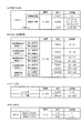
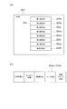
図17は、本実施の形態において特別図柄抽選および普通図柄抽選で用いられる乱数(判定テーブル)の構成例を示す図である。
図17(a)には特別図柄抽選で用いられる大当たり乱数の構成例、図17(b)には特別図柄抽選で用いられる大当たり図柄乱数の構成例、図17(c)には特別図柄抽選で用いられるリーチ乱数の構成例、図17(d)には普通図柄抽選で用いられる当たり乱数の構成例が、それぞれ示されている。
[Random number judgment method]
Here, a determination method using random numbers performed in the jackpot determination process (FIG. 9), the variation pattern selection process (FIG. 10), the normal symbol process (FIG. 13), and the like will be described in detail.
FIG. 17 is a diagram showing a configuration example of a random number (determination table) used in the special symbol lottery and the normal symbol lottery in the present embodiment.
FIG. 17A shows a configuration example of a jackpot random number used in the special symbol lottery, FIG. 17B shows a configuration example of the jackpot random number used in the special symbol lottery, and FIG. 17C shows a special symbol lottery. A configuration example of reach random numbers used, and a configuration example of hit random numbers used in normal symbol lottery are shown in FIG.
図17(a)を参照すると、大当たり乱数の判定値として、大当たり判定時のパチンコ遊技機100の遊技状態が低確率状態の場合の大当たりと大当たり判定時の遊技状態が高確率状態の場合の大当たりの2種類と、小当たりとが設定されている。乱数(大当たり乱数)の値の範囲は、何れも0〜299の300個である。低確率状態の特別図柄抽選(大当たり抽選)の場合、当選値は1つだけが設定され、当選確率は1/300である。また高確率状態の特別図柄抽選の場合、当選値は10個設定され、当選確率は10/300(=1/30)である。すなわち図示の例では、高確率状態で始動口121、122に入賞し特別図柄抽選が行われると、低確率状態で特別図柄抽選が行われる場合に比べて、当選確率が10倍となる。また、小当たりの当選値は、低確率状態か高確率状態かに関わらず3個設定され、当選確率は3/300(=1/100)である。
Referring to FIG. 17 (a), as the jackpot random number determination value, the jackpot when the gaming state of the
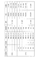
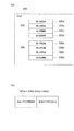
図17(b)を参照すると、大当たり図柄には、低確率図柄A、低確率図柄B、高確率図柄A、高確率図柄B、潜確図柄の5種類が用意されている。ここで、低確率図柄Aおよび低確率図柄Bは、低確率状態の大当たりであることを表す図柄であり、このうち低確率図柄Aは長当たり(低確率時短遊技状態)、低確率図柄Bは短当たり(低確率時短無遊技状態)をそれぞれ表す。高確率図柄Aおよび高確率図柄Bは、高確率状態の大当たりであることを表す図柄であり、このうち高確率図柄Aは長当たり(高確率時短遊技状態)、高確率図柄Bは短当たり(高確率時短無遊技状態)をそれぞれ表す。潜確図柄は、高確率時短無遊技状態の大当たりであることを表す図柄である。したがって、高確率図柄Bと潜確図柄とは大当たり遊技後の遊技状態が同じであるが、潜確図柄は、高確率状態であることを遊技者に明確に報知しない潜伏演出を行う条件とするために高確率図柄Bとは分けて設けられている。乱数の値の範囲は0〜249の250個である。また、大当たり図柄乱数では、特別図柄抽選が行われる契機となる第1始動口121と第2始動口122の各々について当選値が設定される。
Referring to FIG. 17 (b), five types of jackpot symbols are prepared: low probability symbol A, low probability symbol B, high probability symbol A, high probability symbol B, and latent symbol symbol. Here, the low-probability symbol A and the low-probability symbol B are symbols indicating that the low-probability state is a big hit. Of these, the low-probability symbol A is a long win (low-probability short-time gaming state), and the low-probability symbol B is Represents each short hit (low probability, short no-game state). The high-probability symbol A and the high-probability symbol B are symbols representing a jackpot of a high-probability state. Among these symbols, the high-probability symbol A is a long win (high-probability short-time gaming state) and the high-probability symbol B is a short-win ( High probability short-time non-game state). The latent symbol is a symbol representing that it is a big hit in a high probability short-time no-game state. Therefore, the high probability symbol B and the latent probability symbol have the same gaming state after the jackpot game, but the latent probability symbol is a condition for performing a latent effect that does not clearly notify the player that the probability state is high. Therefore, it is provided separately from the high probability symbol B. The range of random number values is 250 from 0 to 249. In addition, in the jackpot symbol random number, a winning value is set for each of the
低確率図柄Aでは、第1始動口121および第2始動口122ともに、当選値として35個の値が割り当てられている。したがって、大当たりに当選した場合に低確率図柄Aでの当選となる確率は、35/250(=7/50)である。
低確率図柄Bでは、第1始動口121および第2始動口122ともに、当選値として15個の値が割り当てられている。したがって、大当たりに当選した場合に低確率図柄Bでの当選となる確率は、15/250(=3/50)である。
In the low probability pattern A, 35 values are assigned as winning values in both the
In the low probability symbol B, 15 values are assigned as winning values for both the
高確率図柄Aでは、第1始動口121に入賞した場合の当選値として25個の値が割り当てられている。したがって、第1始動口121に入賞したことによって開始された特別図柄抽選において大当たりに当選した場合に高確率図柄Aでの当選となる確率は、25/250(=1/10)である。
一方、第2始動口122に入賞した場合の当選値として175個の値が割り当てられている。したがって、第2始動口122に入賞したことによって開始された特別図柄抽選において大当たりに当選した場合に高確率図柄Aでの当選となる確率は、175/250(=7/10)である。
In the high probability symbol A, 25 values are assigned as winning values when winning in the
On the other hand, 175 values are assigned as winning values when winning at the
高確率図柄Bでは、第1始動口121に入賞した場合の当選値として75個の値が割り当てられている。したがって、第1始動口121に入賞したことによって開始された特別図柄抽選において大当たりに当選した場合に高確率図柄Bでの当選となる確率は、75/250(=3/10)である。
一方、第2始動口122に入賞した場合の当選値として25個の値が割り当てられている。したがって、第2始動口122に入賞したことによって開始された特別図柄抽選において大当たりに当選した場合に高確率図柄Bでの当選となる確率は、25/250(=1/10)である。
In the high-probability symbol B, 75 values are assigned as winning values when winning in the
On the other hand, 25 values are assigned as winning values when winning at the
潜確図柄では、第1始動口121に入賞した場合の当選値として100個の値が割り当てられている。したがって、第1始動口121に入賞したことによって開始された特別図柄抽選において大当たりに当選した場合に潜確図柄での当選となる確率は、100/250(=2/5)である。
一方、第2始動口122には潜確図柄での当選値が割り当てられておらず、第2始動口122に入賞した場合に潜確図柄での当選となることはない。
In the latent symbol, 100 values are assigned as winning values when winning at the
On the other hand, the winning value in the latent symbol is not assigned to the
以上のように、図17(b)に示す例では、第1始動口121に入賞した場合の大当たりは、高確率時短無遊技状態の大当たり(高確率図柄B、潜確図柄)となる確率が高く、第2始動口122に入賞した場合の大当たりは、高確率時短遊技状態の大当たり(高確率図柄A)となる確率が高い。このように、第1始動口121に入賞した場合と第2始動口122に入賞した場合における大当たりの種類の当選確率を相違させることにより、様々な遊技性を持たせることができる。また、遊技盤110における第1始動口121と第2始動口122の配置を工夫し、特定の状態(モード)では第1始動口121と第2始動口122の何れか一方を狙い易くなるように構成することによって、遊技者にさらに積極的な遊技への参加を促すことも可能である。
As described above, in the example shown in FIG. 17B, the jackpot when winning the
次に、リーチ乱数の判定について説明する。
図17(c)を参照すると、乱数の値の範囲は0〜249の250個であり、リーチ演出を行う抽選結果(リーチ有)に22個の乱数値が割り当てられ、リーチ演出を行わない抽選結果(リーチ無)に228個の乱数値が割り当てられている。すなわち図示の例では、特別図柄抽選で大当たりしなかった場合に、22/250(=11/125)の確率でリーチ演出が行われる。
Next, the determination of reach random numbers will be described.
Referring to FIG. 17 (c), the range of random number values is 250 from 0 to 249, and 22 random numbers are assigned to the lottery result (with reach) for performing the reach effect, and the reach effect is not performed. 228 random numbers are assigned to the result (no reach). In other words, in the illustrated example, when a special symbol lottery is not won, a reach effect is performed with a probability of 22/250 (= 11/125).
なお、リーチ乱数によって決定されるリーチ有り演出、リーチ無し演出というのは、画像表示部114において行われる演出の態様を示すものである。すなわち、特別図柄の変動表示中には、例えば1〜9の数字が縦方向に連続して記された数列からなる図柄が三列表示されており、特別図柄の変動表示が開始されるのと同時に、これら図柄がスクロールを開始する。
It should be noted that the effect with reach and the effect without reach determined by the reach random number indicate a mode of effect performed in the
そして、リーチ有り演出においては、スクロールの開始後、所定時間経過後にスクロールが停止して各図柄を停止表示する際に、まず、いずれか2つの図柄(数列)が先に停止する。このとき、横または斜めにわたる一直線上に同一の数字が停止表示するとともに、最後の一列がスクロール速度を徐々に遅くして、一直線上に同一の数字が3つ揃うのではないかという期待感を遊技者に与える。このようなリーチ有り演出のなかには、最後の1列のスクロールが停止する前に、さまざまなキャラクタが登場したり、ストーリーが展開したりするいわゆるSP(スーパー)リーチ演出や、SP・SPリーチ演出が含まれている。また、後述する図18に示すように、本実施の形態では、変動時間がより長い(例えば90秒や60秒)場合に、SPリーチやSP・SPリーチ演出を実行するように設定している。一方、リーチ無し演出は、リーチ有り演出とは異なり、遊技者に期待感を与えるような演出がなされることなく、横または斜めにわたる一直線上に同一の数字が揃わない状態で図柄が停止表示するものである。 Then, in the effect with reach, when the scrolling is stopped and the symbols are stopped and displayed after elapse of a predetermined time after the start of the scrolling, any two symbols (sequences) are stopped first. At this time, the same number is stopped and displayed on a straight line extending horizontally or diagonally, and the last one row gradually decreases the scrolling speed, and there is a sense of expectation that three identical numbers will be aligned on the straight line. Give to the player. Among such effects with reach, there are so-called SP (super) reach effects and SP / SP reach effects where various characters appear and stories develop before the last line of scrolling stops. include. Further, as shown in FIG. 18 described later, in this embodiment, when the variation time is longer (for example, 90 seconds or 60 seconds), the SP reach or SP / SP reach effect is set to be executed. . On the other hand, unlike the effect with reach, the effect without reach does not produce an effect that gives the player a sense of expectation, and the symbols stop and display in a state where the same numbers are not aligned on a straight line extending horizontally or diagonally. Is.
このように、リーチ乱数は、大当たり乱数の判定の結果がハズレであった場合に、画像表示部114においてリーチ有り演出を行うか、リーチ無し演出を行うかを決定するためのもので、所定の確率でリーチ有り演出が出現するようにして、遊技者に対して適度に期待感を与えるようにしている。
付言すると、大当たりに当選した場合には、リーチ有り演出が必ず行われ、最終的に横または斜めにわたる一直線上に、同一の数字が揃った状態で装飾図柄が停止表示する。これに対して、小当たりに当選した場合やハズレの場合のリーチ有り演出は、上記一直線上に、同一の数字が揃わない状態で装飾図柄が停止表示する。
As described above, the reach random number is used to determine whether to perform an effect with reach or an effect without reach in the
In addition, when a big win is won, a reachable effect is always performed, and finally the decorative symbols are stopped and displayed in a state where the same numbers are aligned on a straight line extending horizontally or diagonally. On the other hand, in the case of winning with a small win or loss, the decorative symbols are stopped and displayed in a state where the same numbers are not aligned on the straight line.
次に、普通図柄抽選に用いられる大当たり乱数の判定について説明する。
図17(d)を参照すると、乱数の値の範囲は0〜9の10個であり、時短フラグOFFのときの当選値として1個の値が割り当てられ、時短フラグONのときの当選値として9個の値が割り当てられている。したがって、時短無状態のときにゲート124を遊技球が通過して普通図柄抽選(開閉抽選)が行われると、1/10の確率で当選する。これに対し、時短状態のときにゲート124を遊技球が通過して普通図柄抽選(開閉抽選)が行われると、9/10の確率で当選する。
Next, the determination of the jackpot random number used for the normal symbol lottery will be described.
Referring to FIG. 17D, the range of the random number value is 10 from 0 to 9, and one value is assigned as the winning value when the time-short flag is OFF, and as the winning value when the time-short flag is ON. Nine values are assigned. Therefore, when the game ball passes through the gate 124 and the normal symbol lottery (open / close lottery) is performed in the timeless state, the player wins with a probability of 1/10. On the other hand, if the game ball passes through the gate 124 and the normal symbol lottery (open / close lottery) is performed in the short-time state, the player wins with a probability of 9/10.
各種の抽選に用いられる判定情報としての乱数値は、所定の初期値から始まって、図5−3に示す乱数更新処理(S501)が行われるたびに1ずつ加算される。そして、各抽選が行われた時点の値が始動口スイッチ処理(図6)およびゲートスイッチ処理(図7)で取得され、特別図柄処理(図8)や普通図柄処理(図13)で使用される。なお、この乱数値のカウンタは無限ループカウンタであり、設定されている乱数の最大値(例えば図17(a)に示した大当たり乱数では299)に達した後は再び0に戻る。また、乱数更新処理は一定時間ごとに行われるため、各乱数の初期値が特定されてしまうと、これらの情報に基づいて当選値が推定される恐れがある。そこで、一般に、適当なタイミングで各乱数の初期値をランダムに変更する仕組みが導入されている。
なお、図17の各乱数の構成例に示した乱数の範囲、当選値の割合、当選値の各値は例示に過ぎず、図示の値に限定されるものではない。
A random value as determination information used for various types of lottery starts from a predetermined initial value and is incremented by one each time the random number update process (S501) shown in FIG. 5-3 is performed. Then, the values at the time each lottery is performed are acquired by the start opening switch process (FIG. 6) and the gate switch process (FIG. 7), and used in the special symbol process (FIG. 8) and the normal symbol process (FIG. 13). The Note that this random value counter is an infinite loop counter, and returns to 0 again after reaching the maximum value of the set random number (for example, 299 for the jackpot random number shown in FIG. 17A). In addition, since the random number update process is performed at regular intervals, if the initial value of each random number is specified, the winning value may be estimated based on such information. Therefore, in general, a mechanism for randomly changing the initial value of each random number at an appropriate timing has been introduced.
Note that the random number range, winning value ratio, and winning value shown in the configuration example of each random number in FIG. 17 are merely examples, and are not limited to the illustrated values.
〔変動パターンの設定例〕
次に、図10に示した変動パターン選択処理において用いられる変動パターンとテーブルの設定例について説明する。
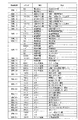
図18は、図10に示した変動パターン選択処理において用いられる変動パターンとテーブルの設定例を示す図である。なお、図18には、第1始動口121に遊技球が入賞した場合であって、遊技状態が低確率時短無遊技状態もしくは高確率時短無状態の場合に選択される設定例を示している。
なお、本実施の形態では、図示を省略しているが、変動パターン選択処理に用いられる変動パターンの設定として、遊技状態が低確率時短遊技状態もしくは高確率時短遊技状態の場合に選択される変動パターンも存在し、それらの変動パターンを選択する際に参照される時短状態用のテーブルも設けられている。また、各々のテーブルの設定内容は、本実施の形態においてそれぞれ異なるようにしている。さらに、第2始動口122に遊技球が入賞する場合に関しては、同様に、変動パターン選択処理において選択される変動パターンの設定のテーブルが設けられてもよいし、第1始動口121に遊技球が入賞した場合に参照するテーブルを共用して参照するようにしてもよい。
[Setting example of fluctuation pattern]
Next, an example of setting the variation pattern and table used in the variation pattern selection process shown in FIG. 10 will be described.
FIG. 18 is a diagram illustrating a setting example of a variation pattern and a table used in the variation pattern selection process illustrated in FIG. FIG. 18 shows a setting example that is selected when a game ball is won at the
Although not shown in the present embodiment, as the setting of the variation pattern used for the variation pattern selection process, the variation selected when the gaming state is the low probability short gaming state or the high probability short gaming state. There are also patterns, and a table for a short time state which is referred to when selecting these variation patterns is also provided. In addition, the setting contents of each table are different in the present embodiment. Further, regarding the case where a game ball wins at the
図18に示すように、変動パターンA〜Dは、特別図柄抽選の判定結果が大当たりの場合(図10のS1002でYesの場合)に選択される変動パターンである。また、変動パターンE〜Hは、リーチ演出が行われる場合(図10のS1005でYesの場合)に選択される変動パターンである。そして、変動パターンI〜Kは、リーチ演出が行われない場合(図10のS1005でNoの場合)に選択される変動パターンとして設定されている。なお、特別図柄抽選の判定結果が大当たりのときには必ずリーチ演出を行うように構成しているため、変動パターンA〜Dが選択される場合においてリーチ演出の有無は参照されない。 As illustrated in FIG. 18, the variation patterns A to D are variation patterns that are selected when the determination result of the special symbol lottery is a big hit (in the case of Yes in S1002 in FIG. 10). The variation patterns E to H are variation patterns that are selected when a reach effect is performed (Yes in S1005 in FIG. 10). The variation patterns I to K are set as variation patterns that are selected when the reach effect is not performed (No in S1005 in FIG. 10). Since the reach effect is always performed when the determination result of the special symbol lottery is a big hit, the presence or absence of the reach effect is not referred to when the variation patterns A to D are selected.
図18に示す例では、特別図柄抽選の判定結果が大当たりであった場合(図10のS1002でYesの場合)の変動パターンとして、4種類の変動パターンA〜Dが設定されている。また、特別図柄抽選の判定結果がはずれ(図10のS1002でNoの場合)であった場合の変動パターンとして、7種類の変動パターンE〜Kが設定されている。変動時間は、変動パターンAが90秒、変動パターンBが60秒、変動パターンCが30秒、
変動パターンDが15秒、変動パターンEが90秒、変動パターンFが60秒、変動パターンGが30秒、変動パターンHが15秒、変動パターンIが13秒、変動パターンJが7秒、変動パターンKが3秒にそれぞれ設定されている。
In the example illustrated in FIG. 18, four types of variation patterns A to D are set as variation patterns when the determination result of the special symbol lottery is a big hit (in the case of Yes in S1002 in FIG. 10). Also, seven types of variation patterns E to K are set as variation patterns when the determination result of the special symbol lottery is out of place (in the case of No in S1002 in FIG. 10). The fluctuation time is 90 seconds for fluctuation pattern A, 60 seconds for fluctuation pattern B, 30 seconds for fluctuation pattern C,
Fluctuation pattern D is 15 seconds, fluctuation pattern E is 90 seconds, fluctuation pattern F is 60 seconds, fluctuation pattern G is 30 seconds, fluctuation pattern H is 15 seconds, fluctuation pattern I is 13 seconds, fluctuation pattern J is 7 seconds, fluctuation Pattern K is set to 3 seconds.
また、図18に示すように、乱数(変動パターン乱数)の値の範囲は、何れも0〜249の250個である。
そして、特別図柄抽選の判定結果が大当たりであった場合において、変動パターンAには、100個の乱数値が割り当てられ、100/250の確率で90秒の変動時間が設定される。また、変動パターンBには、75個の乱数値が割り当てられ、75/250の確率で60秒の変動時間が設定される。さらに、変動パターンCには、50個の乱数値が割り当てられ、50/250の確率で30秒の変動時間が設定される。そして、変動パターンDには、25個の乱数値が割り当てられ、25/250の確率で15秒の変動時間が設定される。
つまり、特別図柄抽選の判定結果が大当たりであった場合に選択される変動パターンA〜Dのうち、最も高い割合で変動パターンAが選択され、次に高い割合で変動パターンBが選択され、次に高い割合で変動パターンCが選択され、最も低い割合で変動パターンDが選択されるように設定することができる。そして、大当たりに当選した場合、比較的長い時に亘っての変動演出が実行されやすくなっている。
Moreover, as shown in FIG. 18, the range of the value of random numbers (variation pattern random numbers) is 250 from 0 to 249.
When the determination result of the special symbol lottery is a big hit, 100 random numbers are assigned to the variation pattern A, and a variation time of 90 seconds is set with a probability of 100/250. Also, 75 random numbers are assigned to the fluctuation pattern B, and a fluctuation time of 60 seconds is set with a probability of 75/250. Furthermore, 50 random numbers are assigned to the variation pattern C, and a variation time of 30 seconds is set with a probability of 50/250. Then, 25 random numbers are assigned to the variation pattern D, and a variation time of 15 seconds is set with a probability of 25/250.
That is, among the variation patterns A to D selected when the determination result of the special symbol lottery is a big hit, the variation pattern A is selected at the highest rate, the variation pattern B is selected at the next highest rate, and the next It is possible to set so that the variation pattern C is selected at a higher rate and the variation pattern D is selected at the lowest rate. And, when winning the jackpot, it is easy to execute the variation effect over a relatively long time.
また、特別図柄抽選の判定結果がはずれであってリーチ有り演出が行われる場合、変動パターンEには、25個の乱数値が割り当てられ、25/250の確率で90秒の変動時間が設定される。また、変動パターンFには、50個の乱数値が割り当てられ、50/250の確率で60秒の変動時間が設定される。さらに、変動パターンGには、75個の乱数値が割り当てられ、75/250の確率で30秒の変動時間が設定される。そして、変動パターンHには、100個の乱数値が割り当てられ、100/250の確率で15秒の変動時間が設定される。
つまり、特別図柄抽選の判定結果がはずれであってリーチ有り演出が行われる場合に選択される変動パターンE〜Hのうち、最も高い割合で変動パターンHが選択され、次に高い割合で変動パターンGが選択され、次に高い割合で変動パターンFが選択され、最も低い割合で変動パターンEが選択されるように設定することができる。そして、はずれであってリーチ有り演出が行われる場合には、比較的短い時間に亘っての変動演出が実行されやすくなっている。
Also, when the determination result of the special symbol lottery is out of order and an effect with reach is performed, 25 random numbers are assigned to the variation pattern E, and a variation time of 90 seconds is set with a probability of 25/250. The Further, 50 random numbers are assigned to the variation pattern F, and a variation time of 60 seconds is set with a probability of 50/250. Furthermore, 75 random numbers are assigned to the fluctuation pattern G, and a fluctuation time of 30 seconds is set with a probability of 75/250. Then, 100 random numbers are assigned to the variation pattern H, and a variation time of 15 seconds is set with a probability of 100/250.
In other words, the variation pattern H is selected at the highest rate among the variation patterns E to H selected when the determination result of the special symbol lottery is out of order and the effect with reach is performed, and the variation pattern at the next highest rate. It can be set such that G is selected, the variation pattern F is selected at the next highest rate, and the variation pattern E is selected at the lowest rate. When the effect with reach and the effect with reach is performed, the variation effect over a relatively short time is easily executed.
そして、特別図柄抽選の判定結果がはずれであってリーチ無し演出が行われる場合、変動パターンI〜Kには、250個の乱数値が割り当てられる。そして、変動パターンIは保留数が0個であるとき、変動パターンJは保留数が1または2個であるとき、変動パターンKは保留数が3個または4個であるときにそれぞれ選択される変動パターンとして設定されている。すなわち、はずれであってリーチ無し演出が行われる場合、特別図柄抽選における判定の保留数が多いほど、図柄変動の平均時間が短くなるように設定されている。 When the determination result of the special symbol lottery is out of order and a reachless effect is performed, 250 random numbers are assigned to the variation patterns I to K. The variation pattern I is selected when the number of holdings is 0, the variation pattern J is selected when the number of holdings is 1 or 2, and the variation pattern K is selected when the number of holdings is 3 or 4. It is set as a fluctuation pattern. That is, in the case where an effect without reach and a reachless effect is performed, the average time of symbol variation is set to be shorter as the number of pending determinations in the special symbol lottery is larger.
遊技制御部200は、遊技球が始動口121、122に入賞した際に取得した変動パターン乱数値(図6のS603、S610参照)と、パチンコ遊技機100の遊技状態、リーチ演出の有無、保留数等の条件とに基づいて特別図柄の変動パターンを決定する。そして、決定された特別図柄の変動パターンの情報は、変動開始コマンドに含まれて、遊技制御部200から演出制御部300へ送られる。演出制御部300では、後述するように、特別図柄変動時の演出として、変動開始コマンドに含まれる変動パターンの情報に基づいて特定される変動時間に対応する(その変動時間で実行可能な)演出が選択されて実行される。
The
〔コマンドの構成および伝送方式〕
ここで、遊技制御部200から演出制御部300へ出力されるコマンド(演出制御用コマンドおよび設定用コマンド)の構成および伝送方式について説明する。
図19−1は、コマンドの構成を示す図である。図19−1(a)はコマンドのデータ構造を示し、図19−1(b)はコマンドのビット列としての構造を示す。
[Command structure and transmission method]
Here, the configuration and transmission method of commands (effect control commands and setting commands) output from the
FIG. 19A is a diagram illustrating a command configuration. 19A shows the data structure of the command, and FIG. 19A shows the structure of the command as a bit string.
図19−1(a)に示すように、遊技制御部200から演出制御部300へ出力されるコマンドは、1コマンドが2バイトで構成される。このコマンドは、第1データ部としての1バイトの「コード」と、第2データ部としての1バイトの「データ」で構成されている。「コード」は、コマンドの種類を示し、「データ」は、コマンドの値を示す。このコマンドは、1本のシリアル信号により調歩同期を用いて、遊技制御部200から演出制御部300へ送信される。なお、より一般的には、第1データ部である「コード」は、aビット(aは2以上の整数)のサイズで、先頭の1ビットの値が1または0の何れか一方に特定され、第2データ部である「データ」は、n×aビット(nは1以上の整数)のサイズで、先頭の1ビットの値が前記第1データ部の先頭の1ビットの値とは異なる値に特定されている。
As shown in FIG. 19A, a command output from the
調歩同期を用いるため、コマンドを構成する「コード」および「データ」の各々の先頭には1ビットのスタートビット(図中、「S」と記載されたビット)が設けられ、最後尾には1ビットのエンドビット(図中、「E」と記載されたビット)が設けられる。また、コマンドを構成する「コード」および「データ」の各々には1ビットのパリティビット(図中、「P」と記載されたビット)が設けられる。 Since start-stop synchronization is used, a start bit (bit indicated as “S” in the figure) is provided at the head of each of “code” and “data” constituting the command, and 1 at the end. End bits of bits (bits indicated as “E” in the figure) are provided. Each of the “code” and “data” constituting the command is provided with one parity bit (bit indicated as “P” in the figure).
図19−1(a)に示したように、コマンドを構成する「コード」と「データ」とは、どちらも1バイト(8ビット)のデータサイズを有する。そして、伝送される際、「コード」および「データ」には、それぞれ、スタートビット、エンドビットおよびパリティビットが設けられる。そのため、コマンドを受信する演出制御部300において、受信したデータ列がコマンドの「コード」であるのか「データ」であるのかを、データ列の外形から識別することは容易ではない。そこで、本実施の形態では、「コード」と「データ」とを識別するためのフラグを設定する。具体的には、「コード」を構成する8ビット値の特定箇所の値と、「データ」を構成する8ビット値のうち「コード」の特定箇所に対応する箇所の値とが異なるようにする。 As shown in FIG. 19A, both the “code” and “data” constituting the command have a data size of 1 byte (8 bits). When transmitted, the “code” and “data” are provided with a start bit, an end bit, and a parity bit, respectively. For this reason, it is not easy for the presentation control unit 300 that receives a command to identify whether the received data string is a “code” or “data” of the command from the outline of the data string. Therefore, in the present embodiment, a flag for identifying “code” and “data” is set. Specifically, the value of the specific portion of the 8-bit value constituting the “code” is made different from the value of the portion corresponding to the specific portion of the “code” among the 8-bit values constituting the “data”. .
図19−1(b)に示す例では、「コード」および「データ」のそれぞれの先頭の1ビットをフラグとして用いている。すなわち、「コード」を構成する8ビット値においては、先頭の1ビットの値を「1」とし、「データ」を構成する8ビット値においては、先頭の1ビットの値を「0」とする。これにより、演出制御部300は、受信したデータ列のスタートビットに続く先頭の1ビットの値を調べることにより、そのデータ列が「コード」か「データ」かを識別することができる。なお、フラグの具体的な値は例示に過ぎず、「コード」と「データ」とを識別可能であれば、上記に示す値とは異なる値を用いても良い。 In the example illustrated in FIG. 19B, the first 1 bit of each of “code” and “data” is used as a flag. That is, in the 8-bit value constituting the “code”, the first 1-bit value is “1”, and in the 8-bit value constituting the “data”, the first 1-bit value is “0”. . Thereby, the effect control unit 300 can identify whether the data string is “code” or “data” by examining the value of the first 1 bit following the start bit of the received data string. The specific value of the flag is merely an example, and a value different from the above value may be used as long as “code” and “data” can be identified.
ここで、「コード」は先頭の1ビットの値が「1」に特定されているので、「コード」が取り得る値の範囲は、10000000B(=80H)から11111111B(=FFH)までの128個である。なお、各値に付された文字「B」は2進数表記であることを示し、文字「H」は16進数表記であることを示す。また、「データ」は先頭の1ビットの値が「0」に特定されているので、「データ」が取り得る値の範囲は、00000000B(=00H)から01111111B(=7FH)までの128個である。すなわち、図19−1(a)、(b)に示す構成によれば、各々128種類の値を取り得る、128種類のコマンドを設定することができる。 Here, since the value of the first bit of “code” is specified as “1”, the range of values that can be taken by “code” is 128 from 10000000B (= 80H) to 11111111B (= FFH). It is. Note that the letter “B” attached to each value indicates binary notation, and the letter “H” indicates hexadecimal notation. In addition, since the value of the first 1 bit of “data” is specified as “0”, the range of values that “data” can take is 128 from 00000000B (= 00H) to 01111111B (= 7FH). is there. That is, according to the configuration shown in FIGS. 19A and 19B, 128 types of commands that can take 128 types of values can be set.
ところで、パチンコ遊技機100では、遊技状態や特別図柄抽選の判定結果等に応じて多くの種類の演出が実行される。そのため、演出制御用のコマンドも多くのコマンド数が用意される。特に、コマンドの具体的な内容を示す値である「データ」は、上記の128個では不足することもあり得る。一方、コマンドの種類を示す「コード」は、通常、上記の128個よりも小さい数で足りる。そこで、「コード」のビット列の一部を、「データ」の値を記述するために用いることが考えられる。
By the way, in the
例えば、「コード」の最後尾の1ビットを「データ」の値の記述に用いる場合を考える。以下、「コード」および「データ」を構成する8ビットのビット列における各ビットを、第1ビット〜第8ビットと呼ぶ。また、「コード」を構成するビット列とは別に、実際にコマンドの種類を示す「コード」の値を「コード値」と呼び、「データ」を構成するビット列とは別に、実際にコマンドの値を示す「データ」の値を「データ値」と呼ぶ。すると、コード値は、「コード」のビット列のうち、第1ビットから第7ビットまでを用いて記述され、データ値は、「データ」のビット列の全て(第1ビットから第8ビットまで)と、「コード」の第8ビットとを用いて記述される。 For example, consider the case where the last 1 bit of “code” is used to describe the value of “data”. Hereinafter, each bit in the 8-bit bit string constituting “code” and “data” is referred to as first to eighth bits. Separately from the bit string that makes up the “code”, the “code” value that actually indicates the type of command is called the “code value”, and separately from the bit string that makes up the “data”, the actual command value is The value of “data” shown is called “data value”. Then, the code value is described using the first to seventh bits in the “code” bit string, and the data value is all of the “data” bit string (from the first bit to the eighth bit). , And the 8th bit of “code”.
このように構成すれば、コード値の取り得る範囲は、第1ビットの値が「1」に特定されており、全体で7ビットのサイズであるので、1000000B(=40H)から1111111B(=7FH)までの64個である。また、データ値の取り得る範囲は、第1ビットの値が「0」に特定された「データ」の8ビットで表現される128個と「コード」の第8ビットの値「0」、「1」とを合わせて、256個である。したがって、データ値として256種類の値を持つコマンドを設定することが可能となる。 With this configuration, the possible range of the code value is that the value of the first bit is specified as “1” and the total size is 7 bits, so that the range from 1000000B (= 40H) to 1111111B (= 7FH) ) Up to 64). The possible range of the data value is 128 values represented by 8 bits of “data” in which the value of the first bit is specified as “0”, and values “0” and “8” of the 8th bit of “code”. 1 ”is 256. Therefore, it is possible to set a command having 256 kinds of values as data values.
なお、「コード」の一部を用いてデータ値を記述する場合における上記の構成は例示に過ぎず、具体的なビット数や値は上記の構成例には限定されない。例えば、「コード」の第7ビットおよび第8ビットを用いてデータ値を記述するように構成しても良い。より一般的には、第1データ部である「コード」を構成する所定のビットと、第2データ部である「データ」を構成するビットとを用いて、所定の種類のデータ(データ値)が記録される。そして、第1データ部である「コード」における上記の所定のビットを除く残りのビットを用いて、所定の種類のデータ(データ値)とは異なる他の種類のデータ(コード値)が記録される。言い換えると、第2データ部である「データ」を構成するaビットと、第1データ部である「コード」を構成するbビット(bはa−1よりも小さく、1以上の整数)とを用いて、(a+b)ビットのサイズのデータ値が記録される。 Note that the above configuration in the case where a data value is described using a part of the “code” is merely an example, and the specific number of bits and value are not limited to the above configuration example. For example, the data value may be described using the seventh bit and the eighth bit of the “code”. More generally, a predetermined type of data (data value) using a predetermined bit constituting “code” as the first data portion and a bit constituting “data” as the second data portion. Is recorded. Then, by using the remaining bits excluding the predetermined bits in the “code” which is the first data portion, other types of data (code values) different from the predetermined types of data (data values) are recorded. The In other words, a bit constituting “data” as the second data part and b bit (b is smaller than a−1 and an integer of 1 or more) constituting “code” as the first data part. In use, a data value having a size of (a + b) bits is recorded.
また、扱うことができるデータ値の数を増やす手段としては、データ値を記述する「データ」のビット列を増やすことも考えられる。例えば、データ値を記述するビット列として、「第1データ」と「第2データ」とを用意することが考えられる。この場合、各ビット列を8ビットとすれば、合計で16ビットのビット列によりデータ値を記述することが可能となる。「第1データ」と「第2データ」とを識別するために、8ビットのビット列のうち第2ビットをフラグとして用いることにすると、例えば、「第1データ」の第1ビットおよび第2ビットを「00B」とし、「第2データ」の第1ビットおよび第2ビットは「01B」とすることができる。なお、第1ビットは、「コード」と識別するためのフラグとして値「0」となっている。すなわち、第2データ部である「データ」は、個々のデータ値を表すビット列(「第1データ」、「第2データ」、……)のサイズである8ビットごとに(より一般的には、上記aビットごとに)、先頭の1ビットの値と同じ値が設定される。 Further, as a means for increasing the number of data values that can be handled, it is conceivable to increase the bit string of “data” describing the data values. For example, it is conceivable to prepare “first data” and “second data” as bit strings describing data values. In this case, if each bit string is 8 bits, a data value can be described by a bit string of 16 bits in total. In order to distinguish between “first data” and “second data”, if the second bit of the 8-bit bit string is used as a flag, for example, the first bit and the second bit of “first data” Can be “00B”, and the first and second bits of “second data” can be “01B”. The first bit has a value “0” as a flag for identifying “code”. That is, the “data” that is the second data portion is a bit string (“first data”, “second data”,...) That represents each data value every 8 bits (more generally, For each a bit), the same value as the value of the first 1 bit is set.
このように構成すると、「第1データ」の取り得る値の範囲は、00000000B(=00H)から00111111B(=3FH)までの64個であり、「第2データ」の取り得る値の範囲は、01000000B(=40H)から01111111B(=7FH)までの64個であるので、合計で4096(=64×64)個となる。なお、ここでは、「コード」と「データ」(「第1データ」および「第2データ」)を識別するためのフラグとして第1ビットを用い、「第1データ」と「第2データ」とを識別するためのフラグとして第2ビットを用いることとしたが、第1、第2ビットを用いて4種類のビット列を識別するためのフラグを設定しても良い。例えば、「コード」は第1、第2ビットの値を「11B」とし、「データ」は第1、第2ビットの値を「00B」、「01B」、「10B」の何れかとすることが考えられる。 With this configuration, the range of values that the “first data” can take is 64 from 00000000B (= 00H) to 00111111B (= 3FH), and the range of values that the “second data” can take is Since there are 64 from 01000000B (= 40H) to 01111111B (= 7FH), the total is 4096 (= 64 × 64). Here, the first bit is used as a flag for identifying “code” and “data” (“first data” and “second data”), and “first data” and “second data” Although the second bit is used as a flag for identifying the first and second bits, a flag for identifying four types of bit strings may be set using the first and second bits. For example, “code” may have the value of the first and second bits “11B”, and “data” may have the value of the first and second bits “00B”, “01B”, and “10B”. Conceivable.
〔遊技制御部のRAMにおけるコマンド出力のための構成例〕
図19−2は、RAM203におけるコマンド格納領域の構成例を示す図である。
図19−2に示すように、遊技制御部200のRAM203は、図5−3に示した主制御処理等の各種の処理により生成される個々のコマンドが割り当てられたコマンド格納領域(記憶領域)を有する。図19−2に示す例では、領域1から領域31までの31個のコマンド格納領域がRAM203に設定されている。ここで、各コマンド格納領域に対するコマンドの割り当ては、必ずしも1対1の対応関係とはならない。例えば、同時に生成されることがない複数のコマンドを、同一のコマンド格納領域に割り当てることが可能である。図19−2に示す例では、領域1、領域9、領域12、領域19、領域20、領域21、領域22、領域23、領域30に対して複数のコマンドが割り当てられており、その他のコマンド格納領域にはそれぞれ1個ずつのコマンドが割り当てられている。
[Configuration Example for Command Output in RAM of Game Control Unit]
FIG. 19B is a diagram illustrating a configuration example of a command storage area in the
19-2, the
図19−2に示す例において、領域1には、電源投入に関するコマンドが割り当てられている。電源投入に関するコマンドには、RAMクリア時の電源投入を制御するコマンドと、復旧時の電源投入を制御するコマンドとがある。これらのコマンドは、生成される場面が異なるので同時に生成されることがなく、いずれも領域1に割り当てられている。
In the example illustrated in FIG. 19B, a command relating to power-on is assigned to the
領域2〜4には、第1始動口121への入賞に関する3つのコマンド(図では「始動口1入賞」と記載)が割り当てられている。第1始動口121への入賞に関するコマンドの一つは、第1始動口121への入賞に基づく事前判定(図6のS605参照)における判定(先読み)結果を示すコマンド(図では「特図1図柄先読み」と記載)であり、領域2に割り当てられている。他の一つは、判定結果と共に特定される変動パターンの先読み(事前判定)結果を示すコマンド(図では「特図1変動パターン先読み」と記載)であり、領域3に割り当てられている。さらに他の一つは、第1始動口121への入賞に基づき特別図柄抽選の保留数を更新(ここでは値を1増加)したことを示すコマンド(図では「特図1保留(+1)」と記載)であり、領域4に割り当てられている。
In the
領域5〜7には、第2始動口122への入賞に関する3つのコマンド(図では「始動口2入賞」と記載)が割り当てられている。第2始動口122への入賞に関するコマンドの一つは、第2始動口122への入賞に基づく事前判定(図6のS612参照)における判定結果を示すコマンド(図では「特図2図柄先読み」と記載)であり、領域5に割り当てられている。他の一つは、判定結果と共に特定される変動パターンの先読み結果を示すコマンド(図では「特図2変動パターン先読み」と記載)であり、領域6に割り当てられている。さらに他の一つは、第2始動口122への入賞に基づき特別図柄抽選の保留数を更新(ここでは値を1増加)したことを示すコマンド(図では「特図2保留(+1)」と記載)であり、領域7に割り当てられている。
In the
領域8〜10には、普通図柄抽選に関する5つのコマンド(図では、それぞれ「普図保留」、「普図種類」、「普図確定」、「普図開閉」、「普図保留」と記載)が割り当てられている。普通図柄抽選に関するコマンドのうち、「普図保留」コマンドの一つは、遊技球がゲート124を通過したことに基づき普通図柄抽選の保留数を更新(ここでは値を1増加)したことを示すコマンド(図では「普図保留(+1)」と記載)であり、領域8に割り当てられている。「普図種類」コマンドは、普通図柄抽選において、判定結果を表す普通図柄を指定し、普通図柄表示器223の変動表示を開始したことを示すコマンド(図では「普通図柄変動開始」と記載)であり、領域9に割り当てられている。「普図確定」コマンドは、普通図柄抽選において、普通図柄表示器223を停止表示させ、普通図柄抽選の判定結果を表す普通図柄を確定させたことを示すコマンド(図では「普通図柄確定」と記載)であり、領域9に割り当てられている。「普図開閉」コマンドは、普通図柄抽選の判定結果に基づき普通電動役物である電動チューリップ123を作動させること(補助遊技)を示すコマンド(図では「普電開放・閉鎖」と記載)であり、領域9に割り当てられている。「普図保留」コマンドの他の一つは、普通図柄抽選の処理が行われたことにより保留数を更新(ここでは値を1減少)したことを示すコマンド(図では「普図保留(−1)」と記載)であり、領域10に割り当てられている。
In the areas 8 to 10, five commands related to the normal symbol lottery (in the figure, “Temporary Map Hold”, “Typical Map Type”, “Typical Map Confirmation”, “Typical Map Open / Close”, and “Typical Map Hold” are described. ) Is assigned. Of the normal symbol lottery commands, one of the “general symbol hold” commands indicates that the number of normal symbol lotteries has been updated (in this case, the value is increased by 1) based on the fact that the game ball has passed through the gate 124. It is a command (denoted as “general map hold (+1)” in the figure) and is assigned to area 8. The “ordinary symbol type” command designates a normal symbol representing the determination result in the normal symbol lottery, and indicates that the variable symbol display on the
ここで、普通図柄抽選の処理において、普通図柄の変動表示、普通図柄の停止表示、補助遊技による電動チューリップ123の作動は、一連の操作として順次実行される。そして、電動チューリップ123の作動中に他の遊技球がゲート124を通過したことに基づく普通図柄の変動表示が開始されることはない(図13参照)。そのため、上記の「普図種類」、「普図確定」、「普電開閉」の3種類のコマンドは、いずれも同時に生成されることはない。そこで、図19−2に示す例では、これら3種類のコマンドを同一のコマンド格納領域(領域9)に割り当てている。
Here, in the normal symbol lottery process, the normal symbol variation display, the normal symbol stop display, and the operation of the
領域11〜14には、特別図柄抽選に関する9つのコマンド(図では、「特図変動」、「特図特電」と記載)が割り当てられている。特別図柄抽選に関するコマンドのうち、「特図変動」コマンドの一つは、パチンコ遊技機100の現在の遊技状態(高確率状態か低確率状態か、時短状態か時短無状態か)を示すコマンド(図では「遊技状態」と記載)であり、領域11に割り当てられている。「特図変動」コマンドの他の一つは、特別図柄抽選において、特別図柄抽選の判定結果を表す特別図柄を指定し、特別図柄表示器221、222の変動表示を開始したことを示すコマンド(図では「特図指定」と記載)であり、領域12に割り当てられている。「特図変動」コマンドのさらに他の一つは、特別図柄抽選において行われる特別図柄変動の変動パターンを特定するコマンド(図では「変動パターン」と記載)であり、領域13に割り当てられる。「特図変動」コマンドのさらに他の一つは、特別図柄抽選の処理が行われたことにより保留数を更新(ここでは値を1減少)したことを示すコマンド(図では「特図保留(−1)」と記載)であり、領域14に割り当てられている。
In the areas 11 to 14, nine commands related to special symbol lottery (in the figure, described as “special figure variation” and “special figure special electricity”) are assigned. Of the commands related to the special symbol lottery, one of the “special diagram change” commands is a command (indicating whether the current gaming state of the pachinko gaming machine 100 (high probability state or low probability state, short time state or short time state). In the figure, it is described as “gaming state”) and is assigned to the area 11. Another one of the “special symbol change” commands is a command (specifying a special symbol representing the determination result of the special symbol lottery in the special symbol lottery and indicating that the special
一方、「特図特電」コマンドの一つは、パチンコ遊技機100が客待ち状態であることを示すコマンド(図では「客待ち」と記載)であり、領域12に割り当てられている。「特図特電」コマンドの他の一つは、特別図柄抽選の判定結果に基づき特別電動役物である大入賞口125を作動させること(特別遊技、大当たり遊技)を示すコマンド(図では「特電開放」と記載)であり、領域12に割り当てられている。「特図特電」コマンドのさらに他の一つは、大当たり遊技のオープニング動作が開始されたことを示すコマンド(図では「大当たりOP」と記載)であり、領域12に割り当てられている。「特図特電」コマンドのさらに他の一つは、大当たり遊技のエンディング動作が開始されたことを示すコマンド(図では「大当たりED」と記載)であり、領域12に割り当てられている。「特図特電」コマンドのさらに他の一つは、特別図柄表示器221、222を停止表示させ、特別図柄抽選の判定結果を表す特別図柄を確定させたことを示すコマンド(図では「特図確定」と記載)であり、領域12に割り当てられている。
On the other hand, one of the “special drawing special electric power” commands is a command indicating that the
ここで、特別図柄抽選の処理において、特別図柄の変動表示、特別図柄の停止表示、特別遊技による大入賞口125の作動は、一連の操作として順次実行される。そして、特別遊技の実行中に他の遊技球の入賞に基づく特別図柄の変動表示が開始されることはない(図8参照)。また、大当たり遊技では、オープニング動作、大入賞口125の作動、エンディング動作が、一連の操作として順次実行される。そのため、上記の「特図変動」コマンドにおける「特図指定」コマンドおよび5種類の「特図特電」コマンドは、いずれも同時に生成されることはない。そこで、図19−2に示す例では、これら6種類のコマンドを同一のコマンド格納領域(領域12)に割り当てている。
Here, in the special symbol lottery process, the change display of the special symbol, the special symbol stop display, and the operation of the special winning
領域15〜18には、スイッチ検出に関する4つのコマンド(図では「スイッチ通過」と記載)が割り当てられている。スイッチ検出に関するコマンドの一つは、遊技領域111の左側のゲート124Lを遊技球が通過したことを示すコマンド(図では「左ゲート通過」と記載)であり、領域15に割り当てられている。スイッチ検出に関するコマンドの他の一つは、遊技領域111の右側のゲート124Rを遊技球が通過したことを示すコマンド(図では「右ゲート通過」と記載)であり、領域16に割り当てられている。スイッチ検出に関するコマンドのさらに他の一つは、第2始動口122に遊技球が入賞したことを示すコマンド(図では「始動口SW2通過(電チュー)」と記載)であり、領域17に割り当てられている。スイッチ検出に関するコマンドのさらに他の一つは、大入賞口125に遊技球が入賞したことを示すコマンド(図では「大入賞口入賞」と記載)であり、領域18に割り当てられている。
In the areas 15 to 18, four commands related to switch detection (described as “switch passing” in the figure) are assigned. One of the commands related to the switch detection is a command indicating that the game ball has passed through the left gate 124 </ b> L of the game area 111 (described as “pass left gate” in the figure), and is assigned to the area 15. Another command related to the switch detection is a command indicating that the game ball has passed through the
領域19〜30には、エラーに関するコマンド(図では「エラー」と記載)が割り当てられている。パチンコ遊技機100の遊技制御部が検出するエラーとしては、例えば、払出球が皿153(図1、図2(b)参照)に一杯になったことを示す満タンエラー、枠部材150の前面枠が開状態となっていることを示す扉開放エラー、払い出しユニットによる遊技球の払い出しができなくなったことを示す払い出しエラー、ゲートスイッチ214や始動口スイッチ211、212等の各種の検知スイッチが未接続となっていることを示すスイッチ未接続エラー等がある。図19−2に示す例では、これらのエラーが、それぞれ領域19〜23に割り当てられている。また、エラーごとに、各エラーが発生したことを示すコマンド(図では「〜エラー開始」と記載)と、各エラーが解消したことを示すコマンド(図では「〜エラー終了」と記載)とが、同一のコマンド格納領域に割り当てられている。
In the areas 19 to 30, a command related to an error (described as “error” in the figure) is assigned. As an error detected by the game control unit of the
この他、パチンコ遊技機100の仕様や機能に応じて種々の制御項目やエラー項目を設定し、制御項目に応じたコマンド、エラーが発生したことを示すコマンド、エラーの種類によってはエラーが解消したことを示すコマンド等を生成するように構成して良い。そして、これらのコマンドを、コマンド格納領域に適宜割り当てることができる。図19−2に示す例では、領域24〜30に、種々のエラーに関するコマンドが個別に割り当てられている。また、領域31に、特定の入賞を検出して通知するためのコマンド(図では「入賞通知指定」と記載)が割り当てられている。
In addition, various control items and error items are set in accordance with the specifications and functions of the
以上のように、遊技制御部200のRAM203に設けられたコマンド格納領域は、1つのコマンド格納領域に対して一種類または複数種類のコマンドが対応付けられている。そして、図5−3に示した主制御処理において、遊技制御部200は、生成したコマンドを、そのコマンドに対応付けられているコマンド格納領域に格納していく。
ここで、主制御処理では、1サイクルの処理が実行される度に、必ずしも全てのコマンドが生成される訳ではない。例えば、第1始動口121や第2始動口122への入賞がないときは、上記の始動口121、122への入賞に関するコマンドや「特図変動」コマンドは生成されない。また、普通図柄抽選に関するコマンドのうちの「普図開閉」コマンドや「特図特電」コマンドは、これらの電動役物を作動させるべきタイミングでなければ生成されない。また、エラーの発生に関するコマンドは、そもそもエラーが発生していなければ生成されない。
したがって、主制御処理の出力処理(図5−3のS506参照)が行われる際には、通常、RAM203に設けられたコマンド格納領域のうち、いくつかのコマンド格納領域にはコマンドが格納されており、他のコマンド格納領域にはコマンドが格納されていない状態となる。
As described above, in the command storage area provided in the
Here, in the main control process, not every command is necessarily generated every time one cycle of the process is executed. For example, when there is no winning at the
Therefore, when the output process of the main control process (see S506 in FIG. 5-3) is performed, commands are usually stored in some command storage areas of the command storage area provided in the
〔コマンドの出力動作〕
図19−3は、出力制御部240による出力処理の内容を示すフローチャートである。
本実施の形態では、出力制御部240は、図19−2に示したRAM203のコマンド格納領域の上から順に(領域番号の順に)着目し、各コマンド格納領域に格納されているコマンドを出力する。
[Command output operation]
FIG. 19C is a flowchart illustrating the contents of output processing by the
In the present embodiment, the
図19−3に示すように、遊技制御部200の出力制御部240は、まず、RAM203に設けられたコマンド格納領域のうち、先頭のコマンド格納領域(図19−2に示す例では領域1)に着目し(S221)、コマンドが格納されているか否かを調べる(S222)。そして、コマンドが格納されているならば(S222でYes)、出力制御部240は、格納されているコマンドを読み出して演出制御部300へ出力する(S223)。
As shown in FIG. 19-3, the
着目したコマンド格納領域(初期的には領域1)にコマンドが格納されていなかった場合(S222でNo)、またはS223でコマンド格納領域に格納されていたコマンドを出力した後、出力制御部240は、次の領域番号のコマンド格納領域が有るか否かを調べる(S224)。次のコマンド格納領域が有る場合(S224でYes)、出力制御部240は、そのコマンド格納領域に着目し(S225)、S222へ戻って、コマンドの有無の確認(S222)、出力(S223)を繰り返す。そして、最後のコマンド格納領域(図19−2に示す例では領域31)に対して処理を行ったならば、次の領域番号のコマンド格納領域が無いので(S224でNo)、出力処理を終了する。
If no command is stored in the focused command storage area (initially area 1) (No in S222), or after outputting the command stored in the command storage area in S223, the
〔コマンドの出力順の設定〕
主制御処理においては、図6乃至図16を参照して説明した各処理においてコマンドが生成されると、通常、直ちに生成されたコマンドがRAM203の対応するコマンド格納領域に格納される。すなわち、コマンド格納領域へのコマンドの格納は、一般に、コマンドが生成された順に行われる。
一方、図19−3を参照して説明したように、出力制御部240による出力処理では、一定の順序(上記の例では領域番号の順)で各コマンド格納領域に着目し、格納されているコマンドを出力する。すなわち、コマンドの出力は、コマンドが生成された順に関わらず、予め定められた特定の順序で行われる。これは、コマンドに基づく演出制御部300の演出制御において混乱を防ぐために、特定のコマンドに関しては特定の順序で演出制御部300に送信されることが望ましい場合があるためである。すなわち、詳しくは後述するが、演出制御部300は遊技制御部200から受信した順にコマンドに基づく演出制御を実行するため、コマンドを受信する順番が異なることによって、演出制御に矛盾が生じる等の混乱が生じる場合があるので、これを防止する必要がある。
[Set command output order]
In the main control process, when a command is generated in each process described with reference to FIGS. 6 to 16, the generated command is usually stored in a corresponding command storage area of the
On the other hand, as described with reference to FIG. 19C, in the output process by the
〔演出制御部の動作〕
次に、演出制御部300の動作を説明する。
図19−4は、演出制御部300の動作を示すフローチャートである。
演出制御部300の動作は、図19−4(a)に示すメイン処理と、図19−4(b)に示す割り込み処理とからなる。図19−4(a)を参照すると、演出制御部300は、まず起動時に初期設定を行い(S1901)、CTC(Counter/Timer Circuit)の周期設定を行った後(S1902)、設定された周期にしたがって、演出制御において用いられる乱数を更新しながら(S1903)、割り込み処理を受け付ける。
[Operation of production control unit]
Next, the operation of the effect control unit 300 will be described.
FIG. 19-4 is a flowchart showing the operation of the effect control unit 300.
The operation of the effect control unit 300 includes a main process shown in FIG. 19-4 (a) and an interrupt process shown in FIG. 19-4 (b). Referring to FIG. 19-4 (a), the production control unit 300 first performs initial setting at the time of activation (S1901), sets the cycle of the CTC (Counter / Timer Circuit) (S1902), and then sets the cycle. Accordingly, the interrupt process is accepted while updating the random number used in the production control (S1903).
割り込み処理は、S1902で設定された周期にしたがって定期的に行われる。図19−4(b)を参照すると、この割り込み処理において、演出制御部300は、遊技制御部200からのコマンドを受信してコマンド受信処理を行う(S1911)。このコマンド受信処理において、演出パターンが選択される。また、演出制御部300は、遊技者による演出ボタン161等の操作を受け付けるための演出ボタン処理を行う(S1912)。この後、演出制御部300は、選択した演出パターンの情報を含むコマンドを画像/音響制御部310およびランプ制御部320に送信するコマンド送信処理を行う(S1913)。これにより、画像表示部114への画像表示や音響出力、可動役物115の動作、盤ランプ116や枠ランプ157の発光等による演出が行われる。
The interrupt process is periodically performed according to the cycle set in S1902. Referring to FIG. 19-4 (b), in this interruption process, the effect control unit 300 receives a command from the
〔演出制御部によるコマンド受信処理〕
図20は、コマンド受信処理(図19−4(b)のS1911)の内容を示すフローチャートである。
このコマンド受信処理において、演出制御部300は、まず、事前判定結果コマンドを受信したか否かを判断し(S2001)、事前判定結果コマンドを受信したのであれば(S2001でYes)、さらに、保留数増加コマンドを受信したか否かを判断する(S2002)。なお、事前判定結果コマンドおよび保留数増加コマンドは、遊技制御部200において、図6に示した始動口スイッチ処理においてセットされ(S606、S607、S613、S614)、図5−3に示した出力処理(S506)で演出制御部300へ送信されたものである。
そして、演出制御部300は、保留数増加コマンドを受信したと判断した場合(S2002でYes)、RAM303に保持されている保留数の値を1加算する(S2003)。さらに、演出制御部300は、事前判定結果コマンドおよび保留数増加コマンドに基づいて、演出選択処理を行う(S2004)。なお、演出選択処理の内容については後に説明する。
[Command reception processing by the production control unit]
FIG. 20 is a flowchart showing the contents of the command reception process (S1911 in FIG. 19-4 (b)).
In this command reception process, the production control unit 300 first determines whether or not a prior determination result command has been received (S2001), and if a prior determination result command has been received (Yes in S2001), further holds. It is determined whether or not a number increase command is received (S2002). Note that the advance determination result command and the hold number increase command are set in the start port switch process shown in FIG. 6 in the game control unit 200 (S606, S607, S613, S614), and the output process shown in FIG. 5-3. This is transmitted to the effect control unit 300 in (S506).
Then, when it is determined that the hold number increase command has been received (Yes in S2002), the effect control unit 300 adds 1 to the value of the hold number held in the RAM 303 (S2003). Further, the effect control unit 300 performs an effect selection process based on the prior determination result command and the hold number increase command (S2004). The contents of the effect selection process will be described later.
受信したコマンドが事前判定結果コマンドおよび保留数増加コマンドでない場合(S2001およびS2002でNo)、演出制御部300は、受信したコマンドが変動開始コマンドか否かを判断する(S2005)。この変動開始コマンドは、遊技制御部200において、図8に示した特別図柄処理においてセットされ(S811)、図5−3に示した出力処理(S506)で演出制御部300へ送信される。
受信したコマンドが変動開始コマンドであった場合(S2005でYes)、演出制御部300は、演出選択処理を実行する(S2006)。演出選択処理の詳細については後述する。
When the received command is not the advance determination result command and the pending number increase command (No in S2001 and S2002), the effect control unit 300 determines whether the received command is a change start command (S2005). This variation start command is set in the special symbol process shown in FIG. 8 in the game control unit 200 (S811), and transmitted to the effect control unit 300 in the output process (S506) shown in FIG. 5-3.
When the received command is a change start command (Yes in S2005), the effect control unit 300 executes an effect selection process (S2006). Details of the effect selection process will be described later.
受信したコマンドが事前判定結果コマンド、保留数増加コマンドおよび変動開始コマンドでない場合(S2001、S2002およびS2005でNo)、演出制御部300は、受信したコマンドが変動停止コマンドか否かを判断する(S2007)。この変動停止コマンドは、遊技制御部200において、図8に示した特別図柄処理においてセットされ(S814)、図5−3に示した出力処理(S506)で演出制御部300へ送信される。
受信したコマンドが変動停止コマンドであった場合(S2007でYes)、演出制御部300は、変動演出終了中処理を実行する(S2008)。変動演出終了中処理の詳細については後述する。
When the received command is not a prior determination result command, a pending number increase command, or a change start command (No in S2001, S2002, and S2005), the effect control unit 300 determines whether the received command is a change stop command (S2007). ). This variation stop command is set in the special symbol process shown in FIG. 8 in the game control unit 200 (S814), and transmitted to the effect control unit 300 in the output process (S506) shown in FIG. 5-3.
When the received command is a change stop command (Yes in S2007), the effect control unit 300 executes a process during the end of the change effect (S2008). Details of the process during the end of the variation effect will be described later.
受信したコマンドが事前判定結果コマンド、保留数増加コマンド、変動開始コマンドおよび変動停止コマンドでない場合(S2001、S2002、S2005、S2007でNo)、演出制御部300は、受信したコマンドが大当たり演出におけるオープニングを開始するためのオープニングコマンドか否かを判断する(S2009)。このオープニングコマンドは、図11に示した停止中処理においてセットされ(S1118)、図5−3に示した出力処理(S506)で演出制御部300へ送信される。
受信したコマンドがオープニングコマンドであった場合(S2009でYes)、演出制御部300は、大当たり演出選択処理を実行する(S2010)。大当たり演出選択処理の詳細については後述する。
When the received command is not a pre-judgment result command, a pending number increase command, a change start command, or a change stop command (No in S2001, S2002, S2005, S2007), the effect control unit 300 performs an opening in the jackpot effect. It is determined whether or not it is an opening command for starting (S2009). This opening command is set in the stop process shown in FIG. 11 (S1118), and transmitted to the effect control unit 300 in the output process (S506) shown in FIG. 5-3.
When the received command is an opening command (Yes in S2009), the effect control unit 300 executes a jackpot effect selection process (S2010). Details of the jackpot effect selection process will be described later.
受信したコマンドが事前判定結果コマンド、保留数増加コマンド、変動開始コマンド、変動停止コマンドおよびオープニングコマンドでない場合(S2001、S2002、S2005、S2007およびS2009でNo)、演出制御部300は、受信したコマンドが大当たり演出におけるエンディングを開始するためのエンディングコマンドか否かを判断する(S2011)。このエンディングコマンドは、図14に示した大入賞口処理においてセットされ(S1413)、図5−3に示した出力処理(S506)で演出制御部300へ送信される。
受信したコマンドがエンディングコマンドであった場合(S2011でYes)、演出制御部300は、エンディング演出選択処理を実行する(S2012)。エンディング演出選択処理の詳細については後述する。
When the received command is not a prior determination result command, a pending number increase command, a fluctuation start command, a fluctuation stop command, or an opening command (No in S2001, S2002, S2005, S2007, and S2009), the effect control unit 300 determines that the received command is It is determined whether the command is an ending command for starting the ending in the jackpot effect (S2011). This ending command is set in the special winning opening process shown in FIG. 14 (S1413), and transmitted to the effect control unit 300 in the output process (S506) shown in FIG. 5-3.
If the received command is an ending command (Yes in S2011), the effect control unit 300 executes an ending effect selection process (S2012). Details of the ending effect selection process will be described later.
受信したコマンドが事前判定結果コマンド、保留数増加コマンド、変動開始コマンド、変動停止コマンド、オープニングコマンドおよびエンディングコマンドでない場合(S2001、S2002、S2005、S2007、S2009およびS2011でNo)、次に演出制御部300は、受信したコマンドが客待ち状態に移行するための客待ちコマンド受信処理を実行する(S2013)。客待ちコマンド受信処理の詳細については後述する。 If the received command is not a prior determination result command, a pending number increase command, a change start command, a change stop command, an opening command, or an ending command (No in S2001, S2002, S2005, S2007, S2009, and S2011), then the production control unit 300 executes a customer waiting command reception process for shifting the received command to the customer waiting state (S2013). Details of the customer waiting command reception process will be described later.
図21は、モードフラグの設定例を示す図である。
演出制御部300により演出が行われる場合、設定される演出モードに基づき、種々の演出パターンが選択されて実行される。この演出モードは、RAM303にセットされるモードフラグによって決定される。ここで、モードフラグは、0〜4の値のいずれかが設定されており、それぞれAモードからEモードまでの5種類の演出モードが割り当てられている。なお、モードフラグは、特別図柄抽選の抽選結果または特別図柄抽選の抽選回数に応じて設定される。
高確率図柄Aの大当たりにはモードフラグ1が、低確率図柄Aの大当たりにはモードフラグ2が、高確率図柄Bおよび低確率図柄Bの大当たりにはモードフラグ3が、潜確図柄の大当たりおよび小当たりにはモードフラグ4が、それぞれ割り当てられている。ここで、これらの図柄の種類は、図17(b)に示したものと同様である。何れの大当たりにもモードフラグ0は割り当てられていない。なお、モードフラグ1〜4において、特別図柄抽選を所定回数実行することでモードフラグ0が設定される。
さらに、図21に示す例では、変動演出終了中処理で用いられるパラメータM(M値)が、Aモードを除く各モードに対して個別に設定されている。
FIG. 21 is a diagram illustrating a setting example of the mode flag.
When an effect is performed by the effect control unit 300, various effect patterns are selected and executed based on the set effect mode. This effect mode is determined by a mode flag set in the
Furthermore, in the example shown in FIG. 21, the parameter M (M value) used in the process during the end of the changing effect is individually set for each mode except the A mode.
図22は、図20の演出選択処理(S2004、S2006)の内容を示すフローチャートである。
この演出選択処理において、演出制御部300は、まず、遊技制御部200のRAM203から受信した事前判定結果コマンドを解析する(S2201)。さらに、演出制御部300に事前判定情報は、遊技制御部200のRAM203から受信した保留数増加コマンドを解析する(S2202)。そして、演出制御部300は、事前判定結果コマンドおよび保留数増加コマンドに基づいて、事前判定演出パターンを選択する(S2203)。
FIG. 22 is a flowchart showing the contents of the effect selection process (S2004, S2006) of FIG.
In this effect selection process, the effect control unit 300 first analyzes the prior determination result command received from the
ここで、事前判定演出パターンとしては、特別図柄処理による乱数の判定結果の報知の以前に、その特別図柄処理による乱数の判定結果を予告するような各種の演出パターンを設けることができる。例えば、保留表示に事前判定結果を反映させる場合には、大当たり乱数の判定結果に基づいて保留表示を行う保留表示演出を事前判定演出パターンとして設けることができる。その他、複数の図柄変動を跨ぐように連続的に演出を行う所謂連続予告などの演出パターンも事前判定演出パターンとして設けることができる。 Here, as the pre-determined effect pattern, it is possible to provide various effect patterns for announcing the random number determination result by the special symbol process before the notification of the random number determination result by the special symbol process. For example, when the prior determination result is reflected in the hold display, a hold display effect for performing the hold display based on the determination result of the jackpot random number can be provided as the prior determination effect pattern. In addition, it is also possible to provide an effect pattern such as a so-called continuous notice that continuously effects so as to straddle a plurality of symbol variations as a prior determination effect pattern.
そして、演出制御部300は、加算後の保留数の値と、演出選択処理において選択された事前判定演出パターンの情報とが含まれる保留数コマンドをRAM303にセットする(S2204)。なお、保留数コマンドには、CPU311に対して選択された事前判定演出パターンを通知するために、当該パターンを示す情報が含まれる。CPU311は保留数コマンドを受信することで、選択された事前判定演出パターンに対応する画像や音響をVDP314に描画、出力処理させるためのディスプレイリスト等の作成を行う。VDP314は当該ディスプレイリスト等に基づいて、選択された事前判定演出パターンを表すための画像データや音響データをCGROM315やSNDROM316から読み出して、事前判定演出を画像表示部114やスピーカ156を用いて表現する。
Then, the effect control unit 300 sets a hold number command including the value of the hold number after the addition and information on the pre-determined effect pattern selected in the effect selection process in the RAM 303 (S2204). Note that the number-of-holds command includes information indicating the pattern in order to notify the
なお、演出選択処理において、受信したコマンドが、事前判定結果コマンドおよび保留数増加コマンドのいずれでもなければ、S2201〜S2204の処理は行われない。 In the effect selection process, if the received command is neither the prior determination result command nor the pending number increase command, the processes of S2201 to S2204 are not performed.
そして、演出制御部300は、受信した変動開始コマンドを解析する(S2205)。また、演出制御部300は、RAM303の設定からパチンコ遊技機100の現在のモードフラグを参照し(S2206)、RAM303に保持されている保留数の値を1減算する(S2207)。そして、演出制御部300は、変動開始コマンドの解析結果から得られる各種の設定情報(大当たりの種類、大当たり遊技後の遊技状態、変動パターン等の情報)およびモードフラグにより決定される演出モードに基づき、その演出モードで画像表示部114に表示する画像による図柄変動の変動演出パターンを選択する(S2208)。
Then, the effect control unit 300 analyzes the received variation start command (S2205). Further, the effect control unit 300 refers to the current mode flag of the
最後に、演出制御部300は、選択した演出の実行開始を指示する変動演出開始コマンドをRAM303にセットする(S2209)。なお、変動演出開始コマンドには、CPU311に対して選択された変動演出パターンを通知するために、当該パターンを示す情報が含まれる。CPU311は保留数コマンドを受信することで、選択された変動演出パターンに対応する画像や音響をVDP314に描画、出力処理させるためのディスプレイリスト等の作成を行う。VDP314は当該ディスプレイリスト等に基づいて、選択された変動演出パターンを表すための画像データや音響データをCGROM315やSNDROM316から読み出して、変動演出を画像表示部114やスピーカ156を用いて表現する。
Finally, the effect control unit 300 sets a change effect start command for instructing the execution start of the selected effect in the RAM 303 (S2209). Note that the change effect start command includes information indicating the selected change effect pattern to notify the
詳述しないが、S2208における図柄変動の変動演出パターンの選択処理では、演出モードと変動パターンと演出乱数(図19−4のS1903において更新されている乱数の一つであり、変動開始コマンド受信時に演出乱数値を取得している)とに基づいて変動演出パターンが決定される。ここで決定された変動演出パターンに基づいて、装飾図柄の変動表示、背景演出および予告演出が決定される。なお、装飾図柄の変動表示とは、第1特別図柄表示器221または第2特別図柄表示器222で行われる特別図柄の変動表示に伴い、画像表示部114にて行われる演出表示である。この装飾図柄の変動表示において、リーチ演出等が実行される。
Although not described in detail, in the variation effect pattern selection process of symbol variation in S2208, the effect mode, the variation pattern, and the effect random number (one of the random numbers updated in S1903 in FIG. 19-4, when the variation start command is received) The random production pattern is determined based on the production random number value). Based on the determined variation effect pattern, the decorative symbol variation display, the background effect, and the notice effect are determined. The decorative symbol variation display is an effect display performed by the
図23は、図20の変動演出終了中処理(S2008)の内容を示すフローチャートである。
この変動演出終了中処理において、演出制御部300は、まず受信した変動停止コマンドを解析する(S2301)。また、演出制御部300は、RAM303の設定からパチンコ遊技機100の現在のモードフラグを参照する(S2302)。そして、演出制御部300は、変動停止コマンドの解析の結果から得られる特別図柄変動が停止した際の図柄の種類を示す情報に基づいて特別図柄抽選の抽選結果が大当たりまたは小当たりか否かを判断する(S2303)。大当たりまたは小当たりである場合は(S2303でYes)、その大当たりの種類または小当たりに応じて、図21に示した設定例に基づきRAM303にセットされているモードフラグを変更する(S2304)。
FIG. 23 is a flowchart showing the contents of the changing effect end process (S2008) of FIG.
In this variation effect end process, the effect control unit 300 first analyzes the received variation stop command (S2301). Further, the effect control unit 300 refers to the current mode flag of the
一方、特別図柄抽選の抽選結果が大当たりまたは小当たりでない場合(S2303でNo)、次に演出制御部300は、モードフラグの値が0か否かを調べる(S2305)。モードフラグが0でない場合(S2305でNo)、演出制御部300は、パラメータMを1減算し(S2306)、Mの値が0になったか否かを調べる(S2307)。Mの値が0になったならば(S2307でYes)、演出制御部300は、モードフラグを0に設定する(S2308)。 On the other hand, if the lottery result of the special symbol lottery is not a big win or a small win (No in S2303), the effect control unit 300 next checks whether or not the value of the mode flag is 0 (S2305). When the mode flag is not 0 (No in S2305), the effect control unit 300 subtracts 1 from the parameter M (S2306), and checks whether the value of M has become 0 (S2307). If the value of M becomes 0 (Yes in S2307), the effect control unit 300 sets the mode flag to 0 (S2308).
S2305でモードフラグが0であった場合(S2305でYes)、S2307でパラメータMの値が0にならなかった場合(S2307でNo)、またはS2308でモードフラグを0に設定した後、あるいはS2304でモードフラグを変更した後、演出制御部300は、図柄変動の演出の終了を指示するための変動演出終了コマンドをRAM303にセットして、変動演出終了中処理を終了する(S2309)。ここで、図21を参照すると、S2304でモードフラグを変更した場合は、変動演出終了後の演出モードは大当たりの種類に応じた演出モードとなる。また、S2305でモードフラグが0であった場合およびS2308でモードフラグを0に設定した場合は、変動演出終了後の演出モードはAモードとなる。また、S2307でパラメータMの値が0にならなかった場合は、これまでの演出モードが継続される。
If the mode flag is 0 in S2305 (Yes in S2305), if the value of the parameter M is not 0 in S2307 (No in S2307), or after setting the mode flag to 0 in S2308, or in S2304 After changing the mode flag, the effect control unit 300 sets a change effect end command for instructing the end of the design change effect in the
図24は、図20の大当たり演出選択処理(S2010)の内容を示すフローチャートである。
この大当たり演出選択処理において、演出制御部300は、まず受信したオープニングコマンドを解析し(S2401)、モードフラグに基づく演出モードの内容に応じて演出のパターン(大当たり演出パターン)を選択する(S2402)。そして、演出制御部300は、選択した大当たり演出パターンによる演出に用いられる画像データや音響データをROM302から読み出し、これらのデータと共に、選択した演出を指示する大当たり演出開始コマンドをRAM303にセットして、大当たり演出選択処理を終了する(S2403)。これにより、大当たり中の演出が決定される。
FIG. 24 is a flowchart showing the contents of the jackpot effect selection process (S2010) of FIG.
In this jackpot effect selection process, the effect control unit 300 first analyzes the received opening command (S2401), and selects an effect pattern (a jackpot effect pattern) according to the contents of the effect mode based on the mode flag (S2402). . Then, the effect control unit 300 reads image data and sound data used for the effect by the selected jackpot effect pattern from the
図25は、図20のエンディング演出選択処理(S2012)の内容を示すフローチャートである。
このエンディング演出選択処理において、演出制御部300は、まず受信したエンディングコマンドを解析し(S2501)、モードフラグに基づく演出モードの内容に応じて演出のパターン(エンディング演出パターン)を選択する(S2502)。そして、演出制御部300は、選択したエンディング演出パターンによる演出に用いられる画像データや音響データをROM302から読み出し、これらのデータと共に、選択した演出を指示するエンディング演出開始コマンドをRAM303にセットして、エンディング演出選択処理を終了する(S2503)。
FIG. 25 is a flowchart showing the contents of the ending effect selection process (S2012) of FIG.
In this ending effect selection process, the effect control unit 300 first analyzes the received ending command (S2501), and selects an effect pattern (ending effect pattern) according to the contents of the effect mode based on the mode flag (S2502). . Then, the effect control unit 300 reads image data and sound data used for the effect by the selected ending effect pattern from the
図26は、図20の客待ちコマンド受信処理(S2013)の内容を示すフローチャートである。
演出制御部300は、客待ち状態に移行するための客待ちコマンドを受信したか否かを判断する(S2601)。客待ちコマンドを受信した場合(S2601でYes)、演出制御部300は、経過時間の計測を開始し(S2602)、RAM303において計測フラグをONにする(S2603)。一方、受信したコマンドが客待ちコマンドでなかった場合(S2601でNo)、演出制御部300は、RAM303に保持されている計測フラグがONになっているか否かを判断する(S2604)。計測フラグがOFFであれば(S2604でNo)、客待ちコマンド受信処理を終了する。
FIG. 26 is a flowchart showing the contents of the customer waiting command reception process (S2013) of FIG.
The effect control unit 300 determines whether or not a customer waiting command for shifting to the customer waiting state has been received (S2601). When the customer waiting command is received (Yes in S2601), the effect control unit 300 starts measuring the elapsed time (S2602), and turns on the measurement flag in the RAM 303 (S2603). On the other hand, when the received command is not a customer waiting command (No in S2601), the effect control unit 300 determines whether or not the measurement flag held in the
計測フラグがONである場合(S2604でYesまたはS2603でONにした後)、次に演出制御部300は、計測時間があらかじめ定められたタイムアップ時間に達したか否かを判断する(S2605)。タイムアップしていない場合(S2605でNo)、客待ちコマンド受信処理を終了する。一方、タイムアップした場合(S2605でYes)、演出制御部300は、RAM303に保持されている計測フラグをOFFにし(S2606)、客待ち演出を行うための客待ち演出コマンドをRAM303にセットして客待ちコマンド受信処理を終了する(S2607)。
When the measurement flag is ON (Yes in S2604 or after being turned ON in S2603), the effect control unit 300 next determines whether or not the measurement time has reached a predetermined time-up time (S2605). . If the time is not up (No in S2605), the customer waiting command reception process is terminated. On the other hand, when the time is up (Yes in S2605), the effect control unit 300 turns off the measurement flag held in the RAM 303 (S2606), and sets a customer waiting effect command for performing the customer waiting effect in the
以上のようにしてコマンド受信処理が完了すると、RAM303には、変動演出開始コマンド、変動演出終了コマンド、大当たり演出開始コマンド、エンディング演出開始コマンド、客待ち演出コマンドの何れかがセットされている。
When the command reception process is completed as described above, the
図27は、演出ボタン処理(図19−4(b)のS1912)の内容を示すフローチャートである。
この演出ボタン処理において、演出制御部300は、まず遊技者による演出ボタン161等の操作手段が操作されたか否かを判断する(S2701)。ここで、操作手段の操作とは、演出ボタン161が押下されてONとなること、演出キー162の中央キーや周囲キーが押下されてONとなることを含む。また、タッチパネル等、演出ボタン161および演出キー162以外の操作用デバイスがパチンコ遊技機100に設けられている場合は、そのデバイスの操作を検知したことを含む。演出制御部300は、これらのデバイスのコントローラから操作信号を受け付けて、操作が行われたことを検知する。
FIG. 27 is a flowchart showing the contents of the effect button process (S1912 in FIG. 19-4 (b)).
In this effect button process, the effect control unit 300 first determines whether or not an operation means such as the
演出ボタン161等の操作手段が操作されたならば(S2701でYes)、演出制御部300は、操作手段の操作内容を示す情報を含む演出ボタンコマンドをRAM303にセットして演出ボタン処理を終了する(S2702)。
If the operation means such as the
この後、演出制御部300は、図19−4(b)のコマンド送信処理(S1913)を行って、上記のコマンド受信処理および演出ボタン処理でRAM303にセットされたコマンドを画像/音響制御部310およびランプ制御部320に送信する。そして、画像/音響制御部310およびランプ制御部320が、受信したコマンドに基づき、画像表示部114への画像表示、音響出力、可動役物115の動作、盤ランプ116や枠ランプ157の発光等を制御して、設定された演出を実行する。
Thereafter, the effect control unit 300 performs a command transmission process (S1913) of FIG. 19-4 (b), and the command set in the
〔事前判定に基づく予告演出〕
次に、本実施の形態による事前判定に基づく予告演出について説明する。
本実施の形態では、図6を参照して説明したように、第1始動口121(図1または図3参照)に遊技球が入賞して第1始動口スイッチ211(図3参照)がONとなった場合、および第2始動口122(図1または図3参照)に遊技球が入賞して第2始動口スイッチ212(図3参照)がONとなった場合に、乱数の判定(図8のS808、S809参照)が行われる以前に、事前判定処理により事前判定を行う(図6のS605、S612参照)。
[Advance notice based on prior judgment]
Next, a notice effect based on prior determination according to the present embodiment will be described.
In the present embodiment, as described with reference to FIG. 6, the game ball wins the first start port 121 (see FIG. 1 or 3) and the first start port switch 211 (see FIG. 3) is turned on. And when the game ball is won at the second start port 122 (see FIG. 1 or 3) and the second start port switch 212 (see FIG. 3) is turned ON (see FIG. 8 is performed by prior determination processing (see S605 and S612 in FIG. 6).
また、本実施の形態では、上記の事前判定の結果に基づいて、判定結果を遊技者に示唆する予告演出(示唆演出)を行う。この予告演出は、事前判定が行われた入賞球(保留球)に対する図柄変動よりも先に行われる他の入賞球に対する図柄変動の際に実行される。本実施の形態では、保留球は、一つの始動口(第1始動口121または第2始動口122)につき4個を上限としている(図6参照)。また、第2始動口122の保留球の消化を優先するものとする。この場合、例えば、第2始動口122のある保留球について事前判定を行った場合、その保留球についての図柄変動が行われる前に、現在変動中の変動(当該変動と呼ぶ)を含め、最大で4個の入賞球についての図柄変動が行われることとなる。事前判定が行われた保留球に係る予告演出において、その保留球についての図柄変動が行われる前に複数回の図柄変動が行われる場合、その複数回の図柄変動にまたがる予告演出を行っても良い。
Further, in the present embodiment, based on the result of the above prior determination, a notice effect (suggest effect) for indicating the determination result to the player is performed. This notice effect is executed at the time of a symbol change for another winning ball that is performed prior to a symbol change for the winning ball (holding ball) for which a prior determination has been made. In the present embodiment, the upper limit of the number of holding balls is four per one starting port (first starting
〔予告演出を行うための遊技制御部のRAMおよび演出制御部のRAMの構成〕
このような事前判定に基づく予告演出を実行するために、本実施の形態における遊技制御部200のRAM203および演出制御部300のRAM303は、以下のような構成を有する。
図28は、本実施の形態に係る遊技制御部200のRAM203(図3参照)の構成例を説明するブロック図である。図28(a)は、記憶領域204の構成を示すブロック図であり、図28(b)は、図28(a)に示す記憶部の各々の構成を示すブロック図である。
[Configuration of the RAM of the Game Control Unit and the RAM of the Production Control Unit for Performing the Advance Effect]
In order to execute such a notice effect based on the prior determination, the
FIG. 28 is a block diagram illustrating a configuration example of the RAM 203 (see FIG. 3) of the
図28(a)に示すように、RAM203は、大当たり乱数抽選により取得した大当たり乱数を記憶する特別図柄保留記憶領域としての記憶領域204を備えている。この記憶領域204は、第1始動口121の保留数と第2始動口122の保留数の最大値に対応する8つの記憶部を有している(各保留数の上限値が4の場合)。具体的に説明すると、記憶領域204は、第1記憶部204a、第2記憶部204b、第3記憶部204c、第4記憶部204d、第5記憶部204e、第6記憶部204f、第7記憶部204g、第8記憶部204hを有している。
As shown in FIG. 28A, the
また、図28(b)に示すように、これらの記憶部204a〜204hの各々は、入賞した始動口(第1始動口121または第2始動口122)の別を表す情報が記憶される領域と、取得された大当たり乱数が記憶される領域と、図柄乱数が記憶される領域と、リーチ乱数が記憶される領域と、変動パターン乱数が記憶される領域と、を有する。すなわち、記憶部204a〜204hの各々には、大当たり乱数、図柄乱数、リーチ乱数および変動パターン乱数が記憶される。
Further, as shown in FIG. 28 (b), each of these
ここで、各乱数は、第1記憶部204aから順に記憶していく。より具体的に説明すると、例えば、第1記憶部204a〜第8記憶部204hの何れにも乱数が記憶されていないときには、取得した乱数が第1記憶部204aに記憶されることになる。また、例えば、第1記憶部204a〜第4記憶部204dに乱数がすでに記憶されているときには、取得した乱数が第5記憶部204eに記憶されることになる。
Here, each random number is stored in order from the
図29は、本実施の形態に係る演出制御部300のRAM303(図3参照)の構成例を説明するブロック図である。図29(a)は、保留記憶領域305、306の構成を示すブロック図であり、図29(b)は、図29(a)に示す記憶部の各々の構成を示すブロック図である。
図29(a)に示すように、RAM303は、保留球が保留されている状況を記憶する保留状況記憶領域としての第1保留記憶領域305および第2保留記憶領域306を備えている。この第1保留記憶領域305および第2保留記憶領域306は、第1始動口121への入賞に対する保留および第2始動口122への入賞に対する保留にそれぞれ対応しており、各々4つの記憶部を有している。具体的には、第1保留記憶領域305は、第1記憶部305a、第2記憶部305b、第3記憶部305c、第4記憶部305dを有している。また、第2保留記憶領域306は、第1記憶部306a、第2記憶部306b、第3記憶部306c、第4記憶部306dを有している。
FIG. 29 is a block diagram illustrating a configuration example of the RAM 303 (see FIG. 3) of the effect control unit 300 according to the present embodiment. FIG. 29A is a block diagram showing the configuration of the reserved
As shown in FIG. 29 (a), the
また、図29(b)に示すように、これらの記憶部305a〜305d、306a〜306dの各々は、保留フラグをON/OFFする保留フラグ記憶領域と、報知フラグをON/OFFする報知フラグ記憶領域と、を有している。保留フラグは、各記憶部305a〜305d、306a〜306dごとに保留球の有無を識別するためのフラグである。すなわち、例えば第1始動口121への入賞による保留数が3である場合、第1〜3記憶部305a、305b、305cの3つの保留フラグ記憶領域において、保留フラグがONとなる。報知フラグは、個々の保留球に関して事前判定結果に基づいて予告演出を行うと決定されたことを識別するためのフラグである。すなわち、例えば上記3つの保留球に対して事前判定処理(図6のS605、S612および後述の図30参照)が行われ、3番目の保留球に対して予告演出を行うと決定された場合、第3記憶部305cの報知フラグ記憶領域において、報知フラグがONとなる。
As shown in FIG. 29 (b), each of these
すなわち、RAM203およびRAM303は、遊技制御部200および演出制御部300において、所定数を限度として所定の始動条件の成立に基づく始動情報である保留情報を記憶する記憶手段として機能する。また、遊技制御部200は、この始動情報である保留情報に基づいて、この始動情報に対応する前記始動条件の成立を契機とする特別図柄判定部234の判定が行われる前に、特別遊技状態に移行するか否かに関する事前判定処理を行う事前判定手段である。演出制御部300は、事前判定結果を予告(示唆)するための予告演出を行う演出制御手段である。
That is, the
また、特に図示しないが、図28(a)に示した構成とは別に、RAM203は、事前判定情報が記憶される領域(以下、事前判定情報格納領域)を有する。事前判定情報とは、上記の各乱数に基づく事前判定処理(図6のS605、S612参照)によって得られた情報である。事前判定情報の内容は、特別図柄処理(図8参照)における各種の判定結果として得られる情報と同様であり、具体的には、大当たりの種類(大当たり、小当たり、はずれ)、大当たりであった場合にはその大当たりの種類、演出の内容はリーチ有り演出であるのかリーチ無し演出であるのか、変動パターン(変動時間)の内容といったことを示すための情報である。
Although not particularly illustrated, the
〔事前判定処理〕
次に、事前判定処理(図6のS605、S612参照)について詳細に説明する。
本実施の形態における事前判定処理では、遊技制御部200では、図17や図18を参照しながら説明した乱数の構成例と同様の乱数テーブルを用いて以下のとおり事前判定を行う。
[Preliminary judgment processing]
Next, the prior determination process (see S605 and S612 in FIG. 6) will be described in detail.
In the pre-determination process in the present embodiment, the
図30は、本実施の形態に係る事前判定処理(図6のS605、S612)の内容を示すフローチャートである。
図30に示すように、遊技制御部200は、まず、遊技状態が高確率状態か否かを判断し(S3001)、高確率状態であると判断すると(S3001でYes)、高確率状態用のテーブルを選択して、大当たり乱数および大当たり図柄乱数の事前判定を行う(S3002)。一方、S3001でNoと判断した場合には、低確率状態用のテーブルを選択して、大当たり乱数および大当たり図柄乱数の事前判定を行う(S3003)。
FIG. 30 is a flowchart showing the contents of the pre-determination process (S605 and S612 in FIG. 6) according to the present embodiment.
As shown in FIG. 30, the
S3002またはS3003の大当たり乱数および大当たり図柄乱数の事前判定の後、遊技制御部200は、遊技状態が時短状態か否かを判断し(S3004)、時短状態であると判断すると(S3004でYes)、時短状態用のテーブルを選択して、リーチ乱数の事前判定を行う(S3005)。さらに、時短状態用のテーブルを選択して、変動パターン乱数の事前判定を行う(S3006)。
一方、S3004でNoと判断した場合には、時短無状態用のテーブルを選択して、リーチ乱数の事前判定を行う(S3007)。さらに、時短無状態用のテーブルを選択して、変動パターン乱数の事前判定を行う(S3008)。
After pre-determination of the jackpot random number and jackpot symbol random number in S3002 or S3003, the
On the other hand, if it is determined No in S3004, a table for short time and no state is selected and a reach random number is determined in advance (S3007). Further, a table for timelessness and no-time state is selected, and a change pattern random number is preliminarily determined (S3008).
この後、遊技制御部200は、上述のとおり得られた大当たり乱数の事前判定の結果、大当たり図柄乱数の事前判定の結果、リーチ乱数の事前判定の結果、および変動パターンの事前判定の結果を、事前判定情報として事前判定情報格納領域に記憶する(S3109)。さらに、演出制御部300に事前判定情報を送信するために、事前判定情報を含む事前判定結果コマンドをRAM203にセットする(S3010)。
Thereafter, the
ここで、上述の事前判定は、始動口121、122への遊技球の入賞に応じて取得された乱数値(図6のS603、S610参照)と、大当たり判定処理で用いられる判定テーブル(図17参照)と同様の構成の判定テーブルとを用いて行った。すなわち、使用する判定テーブルを選択した後の判定自体は、大当たり判定処理における判定(図9のS901参照)と同様である。そこで、本実施の形態では、特別図柄処理(図8参照)で用いた大当たり判定処理のサブルーチン(図8のS808および図9参照)を呼び出し、上記の事前判定における乱数の判定を行う。
Here, the above-described prior determination includes a random number value (see S603 and S610 in FIG. 6) acquired according to the winning of a game ball to the start
このような構成としたことにより、本実施の形態では、事前判定処理における乱数の判定を行うために、大当たり判定処理とは別に乱数を判定する処理機能(サブルーチン)を用意する必要がない。そのため、制御命令の数を削減し、大当たり判定処理および事前判定処理に関するプログラムのサイズの増大を抑制することができる。また、上記のように、事前判定に用いる判定テーブルを大当たり判定で用いる判定テーブルと同様の構成とする場合には、大当たり判定で用いる判定テーブルを事前判定においても用いるようにしても良い。 With this configuration, in the present embodiment, it is not necessary to prepare a processing function (subroutine) for determining a random number separately from the jackpot determination process in order to determine a random number in the prior determination process. Therefore, the number of control instructions can be reduced, and an increase in the size of the program related to the jackpot determination process and the prior determination process can be suppressed. Further, as described above, when the determination table used for the pre-determination is configured similarly to the determination table used for the jackpot determination, the determination table used for the jackpot determination may also be used for the pre-determination.
また、ここでは特別図柄抽選に関する事前判定(大当たりか否か)についてのみ説明したが、本実施の形態では、特別図柄の変動表示および停止表示を行う際の変動パターンについても、先読み(事前判定)を行う。特別図柄抽選における変動パターンの選択は、始動口121、122への遊技球の入賞に応じて取得された変動パターン選択用の乱数値(図6のS603、S610参照)と変動パターンテーブル(図18参照)とを用いて行われる(図8のS809および図10参照)。したがって、変動パターンの先読みにおいても、入賞時に取得した変動パターン選択用の乱数値と、特別図柄処理の変動パターン選択処理で用いた変動パターンテーブルと同様の構成の先読みテーブルを用いて、選択される変動パターンを先読みすることができる。
Further, here, only the prior determination (whether or not a big win) related to the special symbol lottery has been described, but in the present embodiment, the variation pattern when the special symbol variation display and stop display are performed is also pre-read (preliminary determination). I do. The selection of the variation pattern in the special symbol lottery is performed by selecting a variation pattern selection random number (see S603 and S610 in FIG. 6) and a variation pattern table (see FIG. 18) obtained in accordance with the winning of the game ball to the start
この場合、変動パターン選択処理で選択される変動パターンを先読みするために、特別図柄処理(図8参照)で用いた変動パターン選択処理のサブルーチン(図8のS809および図10参照)を呼び出して用いることができる。また、変動パターン選択の先読みに用いる先読みテーブルに関しても、特別図柄処理の変動パターン選択処理で用いられる変動パターンテーブルを用いて良い。このように構成すれば、変動パターン選択の先読みに関する制御命令の数を削減し、プログラムのサイズの増大を抑制することができる。 In this case, in order to prefetch the variation pattern selected in the variation pattern selection processing, the variation pattern selection processing subroutine (see S809 in FIG. 8 and FIG. 10) used in the special symbol processing (see FIG. 8) is called and used. be able to. Further, regarding the prefetch table used for prefetching of the variation pattern selection, the variation pattern table used in the variation pattern selection processing of the special symbol processing may be used. With this configuration, it is possible to reduce the number of control instructions relating to the prefetching of the variation pattern selection and to suppress an increase in the program size.
なお、事前判定処理と特別図柄変動時の大当たり判定処理とを、同様の判定テーブル群を用い同じサブルーチンにて行った場合、各処理の実行時が異なるために、事前判定結果と特別図柄変動時の大当たり判定処理による判定結果とが異なる場合があり得る。すなわち、事前判定処理の実行後、特別図柄変動開始時までにパチンコ遊技機100の遊技状態(高確率状態か低確率状態か、時短状態か時短無状態か)が変化した場合である。この場合、判定テーブルは遊技状態に応じて異なる種類のものが用いられるため、事前判定処理の実行時と大当たり判定処理の実行時とでは、判定に用いられる具体的な判定テーブルが異なることになる。そのため、始動口121、122への入賞時に獲得した同一の乱数値を使用しても、事前判定結果と大当たり判定処理の判定結果と異なる場合がある。このような場合、演出制御部300において、事前判定処理の実行後、特別図柄変動の開始時までに遊技状態が変化する場合は、事前判定結果に基づく演出を不実行とする(禁則)制御等を行っても構わない。
Note that if the pre-determination process and the jackpot determination process at the time of special symbol change are performed in the same subroutine using the same determination table group, the execution time of each process is different, so the pre-determination result and the special symbol change time There is a case where the determination result by the jackpot determination process is different. That is, it is a case where the gaming state of the pachinko gaming machine 100 (high probability state or low probability state, short time state or short time state) changes after the execution of the pre-determination process until the start of the special symbol change. In this case, since different types of determination tables are used depending on the gaming state, the specific determination table used for determination differs between the execution of the pre-determination process and the execution of the jackpot determination process. . Therefore, even if the same random number value acquired at the time of winning the
〔後付装飾体6の概略構成〕
図31は、ホールに設置された複数のパチンコ遊技機100の斜視図である。
次に、後付装飾体6について説明する。
図31に示すように、本実施の形態におけるパチンコ遊技機100は、パチンコ遊技機100の前側の上部に後付装飾体6を有する。より具体的には、後付装飾体6は、枠部材150の前側の上部であって、左右方向の中央部に設けられる。また、後付装飾体6は、パチンコ遊技機100において枠部材150から最も前側に突出する部分を有する。付言すると、後付装飾体6は、遊技領域111(図1参照)の上方に取り付けられる。
[Schematic structure of the retrofit body 6]
FIG. 31 is a perspective view of a plurality of
Next, the
As shown in FIG. 31, the
この後付装飾体6は、実際に遊技を行っている遊技者に対して印象的な外観となることに加えて、実際に遊技は行っていない遊技者に対して、パチンコ遊技機100の識別力を向上させる。さらに説明をすると、後付装飾体6は、上述のようにパチンコ遊技機100の前側に突出する部分である。したがって、後付装飾体6は、例えばホール店にて複数のパチンコ遊技機100が並べられる島設備の間の通路を歩く遊技者と対峙し、視認しやすい面(側面)を有する。さらに説明をすると、後付装飾体6は、パチンコ遊技機100の前に座って遊技を行っている遊技者の頭よりも上側(あるいは遊技者の頭と同じ程度の高さ)に位置する。このことにより、通路を歩く遊技者は、後付装飾体6をより視認し易い。
In addition to having an impressive appearance for a player who is actually playing a game, the post-decoration
その結果、パチンコ遊技機100の正面だけではなく、パチンコ遊技機100から離れて通路に立つ遊技者もパチンコ遊技機100を識別することが容易となる。このことにより、例えばホール店において、パチンコ遊技機100の使用を促すため島設備などに設けられる立て札を作成することが不要となる。
As a result, not only the front of the
図32(a)は閉鎖された前面枠20に取り付けられた後付装飾体6の側面図であり、図32(b)は開放された前面枠20に取り付けられた後付装飾体6の斜視図である。
次に、図32(a)および(b)を参照しながら、後付装飾体6の取り付け状態について説明をする。
32 (a) is a side view of the
Next, an attached state of the
まず、枠部材150は、縦長の所謂フレーム構造である枠部材本体としての外枠10と、外枠10に対して開閉自在に装着される前面枠(内枠)20とを備えている。
そして、後付装飾体6は、枠部材150の前面枠20に対して固定される。ここで、後付装飾体6は、遊技盤110(図1参照)とは別体として構成されており、遊技盤110が枠部材150に固定されているか否かに関わらず装着可能である。さらに説明をすると、後付装飾体6は、枠部材150に対して後付けすることが可能である。
First, the
The
ここで、後付装飾体6を後付けで装着することにより、前面枠20や遊技盤110の交換をせずに、パチンコ遊技機100の外観を大きく変更し得る。特に、遊技者の視線が集まりやすい前面枠20の前側上部の左右方向中央に後付装飾体6が設けられることから、後付装飾体6の存在により遊技者が受ける印象は大きく変化する。
この後付装飾体6は、遊技盤110を他の機種に切り替える際に交換してもよいし、遊技盤110とは関係なく単独で交換してもよい。付言すると、後付装飾体6は、遊技盤110とともに出荷(販売)してもよいし、遊技盤110とは別に単独で出荷してもよい。
Here, the external appearance of the
The
また、後付装飾体6は、前面枠20の一部を挟み込む(把持する)ことで固定される。より具体的には、前面枠20の上端の左右方向中央の部分を前後方向において挟む(跨ぐ)状態で装着される。また、詳細は後述するが、後付装飾体6は、ドライバ等の工具を用いることなく装着される。また、後付装飾体6は着脱可能であり、一度付けた後付装飾体6を外して、再び前面枠20に取り付けることも可能である。
Further, the
また、図32(a)に示すように、後付装飾体6は、前面枠20の前側に突出する枠突出部21を上下方向に挟むように設けられる。また、後付装飾体6は、前面枠20の後側面に形成された枠凹部23に引っ掛かるように設けられる。これらのことにより、後付装飾体6の上下方向のずれが抑制される。
Further, as shown in FIG. 32A, the retrofit
また、後付装飾体6は、前面枠20に設けられた枠ランプ157の前側を覆う。そして、この枠ランプ157が照射する光を利用することで、後付装飾体6の装飾性が高められる。より具体的には、枠ランプ157の光が後付装飾体6の内部を透過して、後付装飾体6の前面などを光らせる。なお、後付装飾体6自体は、箱状の部材であり、配線やランプなど電気的な部材を備えない。さらに説明をすると、後付装飾体6を装着する際に電気的な接続作業を必要としない。
The
ここで、図32(a)に示すように、ホール店に設置されたパチンコ遊技機100の上方には、データランプと称される表示器(島設備)30が設けられる。この表示器30には、入賞回数や変動回転数、大当たり回数などの各種情報を表示装置に表示したり、大当たり発生時など所定のタイミングにて電飾等を点滅させたりする。
Here, as shown in FIG. 32A, an indicator (island facility) 30 called a data lamp is provided above the
そして、後付装飾体6は、前面枠20が閉じられた状態において、表示器30および前面枠20に後付装飾体6の一部が挟まれて設けられる。この表示器30および前面枠20によって挟まれた部分は、遊技者の手あるいは指よりも間隙が小さく、遊技者が触れ難い領域である。
また、後付装飾体6は、前面枠20が閉じられた状態において、後側の端部が外枠10と対峙する配置である。このことにより、後付け装飾体6が後側に移動する向きに力を受けると、外枠10によって支持され後付装飾体6の移動が抑制される。
The
Further, the
なお、図32(b)に示すように、後付装飾体6の上側の面は、略平面で形成されている。このことにより、後付装飾体6の上下方向の寸法が抑制される。また、後付装飾体6が表示器30と衝突することが抑制される。また、遊技者が表示器30を視認する動作あるいは操作する動作が、後付装飾体6によって妨げられることが抑制される。
In addition, as shown in FIG.32 (b), the upper surface of the retrofit
〔後付装飾体6の詳細構成〕
図33は、後付装飾体6の斜視図である。図34は、後付装飾体6の分解斜視図である。
次に、後付装飾体6の構成について詳細に説明をする。
図33および図34に示すように、後付装飾体6は、枠体61と、枠体61の上側を覆う天板64と、枠体61の前側を覆う前板65と、枠体61に対する位置が変更可能な固定板67と、枠体61に貼り付けられるシール69と、天板64を枠体61に固定するボルトB2とを有する。
以下、天板64、前板65、固定板67、シール69の各々を説明した後に、枠体61について説明をする。
[Detailed configuration of the retrofit 6]
FIG. 33 is a perspective view of the
Next, the configuration of the
As shown in FIG. 33 and FIG. 34, the retrofit
Hereinafter, after explaining each of the
天板64は、樹脂製の板状部材である。天板64は、ボルトB1、B2を介して枠体61に固定される。
天板64は、枠体61に引掛ける天爪641と、天板64の厚さ方向の剛性を高める天リブ643と、天板64の板面中央に略U字状に形成された舌部645と、舌部645の下側の面に形成された舌突起647と、ボルトB2を挿入する貫通孔649とを備える。
The
The
前板65は、樹脂製の板状部材である。前板65は、枠体61および天板64と掛り合うことで固定される。さらに説明をすると、前板65は、ボルトB2などの固定具を用いることなく枠体61に固定される。
The
前板65は、ランプの光を透過可能に構成されている。図示の例における前板65は、一部分が他の部分よりも透明度が高くなるように構成されている。
また、前板65は、板面の前側に突出する凸部651と、凸部651の周側面653と、枠体61に引掛ける第1前爪655と、天板64を上側から押さえる第2前爪657と、天板64の下側と対峙する第3前爪659と、枠体61に引掛ける第4前爪(不図示)と、板面の前側に形成され遊技者に対する注意事項を表示する注記領域661とを備える。
The
Further, the
ここで、凸部651は、略円柱状の形状であり、前側の頂面には、装飾が施されている。図示の例では、「風林火山」および「GO!」を含む文字と、4つの菱形(武田家の家紋)の造形とを有する。これらの装飾は、パチンコ遊技機100のタイトルである「武田信玄」に関連する観念を形成する。また、これらの装飾は、前側の頂面に凹凸を施して立体的に構成されている。
Here, the
固定板67は、金属製の板状部材である。固定板67は、上下方向を天板64と枠体61とによって挟まれながら前後方向にスライド可能に設けられる。
固定板67は、後側の端部で略コの字状に折り曲げられた曲げ部671と、長手方向が前後方向に沿うよう形成されたスライド溝673と、長手方向が左右方向に沿うよう形成された前側支持溝675と、前側支持溝675よりも後側で前側支持溝675と並ぶよう形成された後側支持溝677と、天板64の舌突起647を案内する案内爪679とを有する。なお、固定板67は、曲げ部671により、後側凹部680が形成された構成となる。
The fixed
The fixed
シール69は、略円形の樹脂製薄膜である。図示の例では2枚のシール69が、枠体61の左右両側面に貼り付けられる。このシール69は、外周部にシール切欠691を備える。また、シール69の表面には、「武田信玄」および「GO!」の文字と、4つの菱形の造形とを有する画像が形成されている。これらの装飾は、パチンコ遊技機100のタイトルおよび「武田信玄」に関連する観念を形成する。
The
なお、図示のシール69は、表面にパチンコ遊技機100に関する情報が表示されている構成として捉えることもできる。ここで、パチンコ遊技機100に関する情報とは、例えばパチンコ遊技機100のタイトル(機種名)や、パチンコ遊技機100の製造者名(メーカー名)、パチンコ遊技機100の演出に登場するキャラクタの画像や名称、あるいはパチンコ遊技機100の当選確率などを含む。
The illustrated
〔枠体61の構成〕
図35(a)は、枠体61を後側からみた斜視図であり、図35(b)は枠体61の正面図であり、図35(c)は枠体61を右側からみた側面図である。
次に、枠体61の構成について説明する。
[Configuration of Frame 61]
FIG. 35A is a perspective view of the
Next, the configuration of the
図34および図35に示すように、枠体61は、樹脂製であり、前後両側が開放された箱状部材である。言い替えると、枠体61は、前後方向に貫通した中空部材である。ここで、枠体61は、上面611、下面613、左側面615および右側面617を有する。
また、枠体61は、上面611に形成され天板64の天爪641を受ける上面溝621と、固定板67のスライド溝673内部に配置される上面突起623と、上面611の厚さ方向の剛性を高める上面リブ625と、上面611の下側の面に形成されボルトB2を受けるボルト孔626とを備える。
As shown in FIGS. 34 and 35, the
Further, the
また、枠体61は、左側面615に貼り付けられるシール69の外周を囲う左周壁627と、左周壁627の内周側に設けられた左内周爪6271と、右側面617に貼り付けられるシール69の外周を囲う右周壁629と、右周壁629の内周側に設けられた右内周爪6291とを備える。なお、左内周爪6271および右内周爪6291に対して、シール切欠691の位置を合わせることで、シール69の貼り付け位置(角度)が定まる。
The
また、枠体61は、前側において前板65を支持する前支持部630を備える。この前支持部630は、正面視略口の字状の平面により構成される。また、前支持部630は、左側面615および右側面617によって左右方向が挟まれた位置である。また、前支持部630の支持面は下側に進むに従い後側に傾斜するため、この前支持部630によって支持された前板65は前側の面が下側に傾いた状態となる。
The
また、枠体61は、前支持部630に形成され前板65の第1前爪655を受ける前溝631と、前板65の第4前爪(不図示)を受ける下溝633と、下面613の後側に設けられ枠ランプ157に対して押しつけられる下突起635と、上面611の後側に設けられ枠ランプ157に対して押しつけられる上突起636と、下面613の厚さ方向の剛性を高める下リブ637とを備える。
また、枠体61は、左側面615および右側面617の後側に枠切欠638を有する。なお、図35(c)に示すように、枠体61は、枠切欠638により、前側凹部620が形成された構成となる。
Further, the
The
〔固定板67のスライド動作〕
図36(a)は、固定板67と天板64および枠体61との配置を示す図であり、図36(b)は図36(a)のB−Bにおける断面を示す図であり、図36(c)は図36(b)から固定板67がスライド移動した後の状態を示す図である。
図37は、前面枠20に装着される固定板67のスライド動作を示す図である。
[Sliding motion of fixing plate 67]
36 (a) is a view showing the arrangement of the fixed
FIG. 37 is a diagram illustrating a sliding operation of the fixing
次に、図36および図37を参照しながら、固定板67のスライド動作について説明をする。
まず、図36(a)に示すように、固定板67は、天板64および枠体61によって案内されながら前後方向にスライド移動が可能である。
具体的に説明をすると、固定板67のスライド溝673には、枠体61の上面突起623が配置される。このことにより、固定板67は、左右方向の移動は制限されつつ、前後方向の移動は許容された状態となる。
Next, the sliding operation of the fixing
First, as shown in FIG. 36A, the fixed
Specifically, the
また、図36(b)および(c)に示すように、固定板67の前側支持溝675あるいは後側支持溝677の内部に、天板64の舌突起647が配置される。なお、上記では説明を省略したが、天板64の舌突起647は、前側面6471と、後側に進むに従い突出量が低くなる向きに傾斜したテーパ面6473とを有する。
そして、固定板67が前後方向にスライド移動することにともない、天板64の舌突起647が、固定板67の前側支持溝675および後側支持溝677の間で移動する。このことにともない、固定板67が天板64から突出する部分の長さが変化する。
36B and 36C, the
As the fixing
さらに説明をすると、図36(b)に示すように、天板64の舌突起647が、固定板67の前側支持溝675に配置されている状態においては、固定板67の曲げ部671は、天板64に対してより遠い位置となる。すなわち、天板64から曲げ部671までの間隔が広い。なお、以下では図36(b)に示す固定板67の配置を第1配置とすることがある。
More specifically, as shown in FIG. 36 (b), when the
一方、図36(c)に示すように、天板64の舌突起647が、固定板67の後側支持溝677に配置されている状態においては、固定板67の曲げ部671は、天板64に対して近い位置となる。すなわち、天板64から曲げ部671までの間隔が狭い。なお、以下では図36(c)に示す固定板67の配置を第2配置とすることがある。
On the other hand, as shown in FIG. 36 (c), when the
さて、図36(b)に示すように、固定板67の案内爪679は、天板64の舌突起647を前側支持溝675から後側支持溝677に向けて移動し易くする。すなわち、案内爪679が弾性変形しながらテーパ面6473を案内することにより、舌突起647が前側支持溝675から後側に向けて移動することが補助される。したがって、固定板67が第1配置(図36(b)参照)から第2配置(図36(c)参照)になることが促進される。
Now, as shown in FIG. 36 (b), the
また、図36(c)に示すように、第2配置、すなわち後側支持溝677内に舌突起647が配置された際には、前側面6471が後側支持溝677の内周面と対峙する。このことにより、前側面6471が後側支持溝677に引掛り、舌突起647が後側支持溝677から前側に移動することが抑制される。すなわち、固定板67が第2配置(図36(c)参照)から第1配置(図36(b)参照)になることが制限される。
As shown in FIG. 36C, when the
次に、図37を参照しながら、後付装飾体6の取り付け時における固定板67のスライド動作について説明する。
まず、図37の破線で示すように、後付装飾体6の製品出荷時には、固定板67が第2配置に設定される。すなわち、天板64から曲げ部671までの間隔を拡げておく。
そして、ホール店にて前面枠20に後付装飾体6を装着する際に、図37の実線で示す後付装飾体6のように、固定板67をスライドさせ、天板64から曲げ部671までの間隔を狭くする。このことにより、固定板67が第1配置に配置される。
Next, referring to FIG. 37, the sliding operation of the fixing
First, as shown by a broken line in FIG. 37, the fixed
When the
ここで、前面枠20に後付装飾体6を装着する過程をより詳細に説明する。
まず、前面枠20の後側における所定の位置(枠凹部23)に、曲げ部671を引掛けるとともに、枠体61の枠切欠638の位置を枠突出部21に合わせることで位置合わせをする(1段階目)。そして、固定板67を第2配置から第1配置に切り替える(2段階目)。付言すると、図示の例においては枠体61を後側(固定板67の曲げ部671側)に押し込むことで、固定板67が第1配置となる。
このように、2段階の作業で、後付装飾体6が前面枠20に固定される。また、この作業においては、ドライバなどの工具を用いることなく後付装飾体6が固定される。
Here, the process of attaching the
First, the
Thus, the
さて、前面枠20に後付装飾体6を取り外す際には、前面枠20を開放した後に、舌部645を起こす(上側に向けて移動させる)。このことにより、後側支持溝677(図36(c)参照)の外へ舌突起647(図36(c)参照)が移動する。すなわち、舌突起647による固定板67の移動制限が解除される。その結果、固定板67がスライドし得る状態となり、固定板67の第1配置から第2配置への切り替えも可能となる。この状態において、固定板67を第2配置とすることで、前面枠20から後付装飾体6を取り外すことが可能となる。
Now, when the retrofitting
なお、後付装飾体6の取り外しのために、舌部645を起こすという所定の操作を必要とすることで、後付装飾体6の脱落が抑制される。さらに説明をすると、例えば前面枠20が開放された状態であっても、所定の操作をしなければ、後付装飾体6は落下しない。また、遊技者が後付装飾体6を押す、あるいは殴打した場合であっても外れ難くなる。
In addition, since the predetermined operation of raising the
さて、図37に示すように、前面枠20が閉じられた状態においては、舌部645は表示器30と前面枠20との間に挟まれる。このことにより、例えば遊技者のいたずらで後付装飾体6が取り外されることが抑制される。また、舌部645は、根元が前側で先端が後側の向きに配置される。したがって、遊技者がパチンコ遊技機100の前側から表示器30と前面枠20との間に手を入れたとしても、舌部645を起こす作業を実行することは困難である。
Now, as shown in FIG. 37, the
〔枠ランプ157に対する配置〕
図38(a)は、枠ランプ157周辺の斜視図であり、図38(b)は後付装飾体6の枠体61を装着した状態の枠ランプ157周辺の斜視図である。
次に、図38を参照しながら、枠ランプ157に対する後付装飾体6の配置について説明をする。
[Arrangement with respect to frame lamp 157]
38A is a perspective view of the periphery of the
Next, the arrangement of the
まず、図38(a)に示すように、枠ランプ157は、発光源となるランプ本体16と、枠ランプ157の前側でランプ本体16よりも下方に形成される下側溝17と、枠ランプ157の前側でランプ本体16よりも上方に形成される上側溝18とを備える。
そして、下側溝17と上側溝18とに対して、枠体61が掛かり合う。言い替えると、枠ランプ157および枠体61が、互いの凹凸を組み合わせることにより枠体61の位置が保持される。
First, as shown in FIG. 38A, the
The
より具体的には、図38(b)に示すように、枠ランプ157の下側溝17内には、枠体61の下突起635が進入する。また、枠ランプ157の上側溝18には、枠体61の上突起636が進入する。また、下側溝17と下突起635との左右方向の長さは互いに対応している。また、上側溝18と上突起636との左右方向の長さは互いに対応している。このことにより、枠体61が上下方向および左右方向においてずれることが抑制される。
More specifically, as shown in FIG. 38 (b), the
〔透過光〕
図39は、後付装飾体6を透過する光の光路を説明する図である。より詳細には、図39は上側から前板65の板面に沿う方向で前板65周辺をみた図である。
次に、図39を参照しながら、後付装飾体6を透過する光の光路を説明する。上述のように、後付装飾体6は枠ランプ157の光を透過させる。より具体的には、枠ランプ157から出射した光は、所定の角度で広がりながら、後付装飾体6を通過する。このとき後付装飾体6を通過した光は、前板65の凸部651の前側だけでなく、左側あるいは右側に向けても出射する。すなわち、凸部651の周側面653からも光が出射する。
〔Transmitted light〕
FIG. 39 is a view for explaining an optical path of light transmitted through the
Next, with reference to FIG. 39, an optical path of light transmitted through the
ここで、凸部651の周側面653を透過した光は、左側面615および右側面617によって遮蔽される。このことにより、周囲の遊技者へ凸部651からの光が到達することが抑制される。このことにより、例えばパチンコ遊技機100の遊技状態の変化に応じて枠ランプ157の発光態様を切り替える場合であっても、周囲の遊技者にその遊技状態の変化を知られることが抑制される。すなわち、パチンコ遊技機100の正面で実際に遊技を行う遊技者のみがパチンコ遊技機100の遊技状態を認識できる。
また、凸部651の周側面653を透過した光は、左側面615および右側面617の内側を照射するとともに、一部が左側面615および右側面617によって反射されることにより、枠ランプ157による演出の効果を高める。
Here, the light transmitted through the
Further, the light transmitted through the
〔いたずら防止〕
さて、本実施の形態における後付装飾体6は、上述のように前面枠20の外側に突出するため、遊技者によるいたずらを受ける可能性がある。そこで、図示の例の後付装飾体6においては、後付装飾体6に対するいたずらを抑制するための構成が採用されている。以下、いたずらを抑制するための構成について説明をする。
[Tamper prevention]
Now, since the
図40は、図33のC−Cにおける断面図である。
まず、上述のように前板65は、第1前爪655(図34参照)を介して枠体61に対して固定される。そして、この前板65を取り外す場合には、第1前爪655が前板65の板面に沿う形状であることから、前板65を上側に移動させることが必要である(図40における矢印参照)。
40 is a cross-sectional view taken along the line CC of FIG.
First, as described above, the
ここで、前板65が上側へ移動することを抑制するために、図示の例においては天板64が前板65の上側端部を覆う。また、天板64は、第3前爪659の上側も覆う。
また、天板64自体が上側に移動することを抑制するため、前板65の第2前爪657が、天板64の上面を押さえている。
上記の配置により、いたずらにより前板65が外されることが抑制される。なお、修理などで前板65を外す際には、ボルトB2(図34参照)を外せばよい。
Here, in order to suppress the
Further, the second
With the above arrangement, the
図41(a)は枠体61に貼り付けられたシール69の斜視図であり、図41(b)は図41(a)のD−Dにおける断面図である。
図41(a)に示すように、シール69は、枠体61の外周面に貼り付けられる。枠体61に貼り付けられたシール69は、その外周が右周壁629あるいは左周壁627(図34参照)によって囲まれる。このことにより、シール69を剥がすいたずらが抑制される。
41A is a perspective view of the
As shown in FIG. 41A, the
なお、図41(b)に示すように、右周壁629あるいは左周壁627(図34参照)が、シール69よりも突出している。また、右周壁629とシール69との間の隙間Laが小さくなるような寸法で、シール69が形成されている。図示の例においては、隙間Laが、右周壁629(左周壁627)の高さLbよりも小さくなるように形成されている。これらのことによっても、シール69を剥がすいたずらが抑制される。
41B, the right
ここで、図35(a)に示すように、下リブ637の間隔Lcは、遊技球の直径よりも小さい。このことにより、下リブ637の間に遊技球を詰めるいたずらが抑制される。なお、図37に示すように、下リブ637は、枠体61における後側を向く面に形成されている。このことにより、下リブ637は遊技者から見えにくくなる。
また、図39に示すように、前板65は、枠体61の左側面615および右側面617によって挟み込まれる。このことによっても、前板65を外すいたずらが抑制される。
Here, as shown in FIG. 35A, the interval Lc between the
Also, as shown in FIG. 39, the
〔変形例1〕
上記の説明においては、後付装飾体6をパチンコ遊技機100の上側中央部に設けることを説明したが、これに限定されない。パチンコ遊技機100の上側両端、あるいはパチンコ遊技機100の左右両側、パチンコ遊技機100の下側などに設けられてもよい。あるいは、パチンコ遊技機100におけるこれらの位置に、複数の後付装飾体6を設けてもよい。
[Modification 1]
In the above description, it has been described that the
また、後付装飾体6をパチンコ遊技機100と別体として設けることを説明したが、これに限定されない。パチンコ遊技機100の前側に突出し側面が形成される態様であれば、後付装飾体6が前面枠20と一体で形成されてもよい。
また、後付装飾体6を枠部材150の前面枠20に対して固定することを説明したが、これに限定されない。前面枠20の開放を許容する態様であれば、枠部材150の他の部分、例えば外枠10に対して後付装飾体6を固定してもよい。
Moreover, although providing the
Moreover, although fixing the
また、後付装飾体6は、パチンコ遊技機100に関する情報を表示しなくともよい。
また、後付装飾体6全体をキャラクタの顔や体全体の形状とするなどしてもよい。
また、固定板67がスライド機構を備えなくてもよい。固定板67の弾性変形を利用することや、嵌め合わせなどにより前面枠20に固定してもよい。
Further, the
Further, the
Further, the fixed
〔変形例2〕
図42は、後付装飾体6の他の変形例を説明するための図である。さらに説明をすると、図42は、後付装飾体6が設けられたスロットマシン900の概略側面図である。
さて、上記の説明においては、後付装飾体6がパチンコ遊技機100に設けられることを詳細に説明したが、パチンコ遊技機100以外の遊技機に設けられてもよい。
[Modification 2]
FIG. 42 is a diagram for explaining another modified example of the
In the above description, it has been described in detail that the
例えば、図42に示すように、スロットマシン900に後付装飾体6が設けられてもよい。
さらに説明をすると、図42に示すスロットマシン900は、回転しながら複数種類の図柄を例えば上から下へと循環させるように表示するリール901と、メダルが投入されるメダル投入口903と、リール901の回転を開始させるために操作される操作レバー905と、リール901の回転を停止させるために操作されるストップボタン907と、メダルが払い出されるメダル払出口909と、遊技に応じて表示による演出や情報表示を行う液晶ディスプレイ911とを備える。
そして、このスロットマシン900は、前側上部で左右方向中央に後付装飾体6を備える。
For example, as shown in FIG. 42, the
More specifically, a
The
◆上記のように、本実施の形態では、興趣性を高めた遊技機などを提供するために、以下の構成を採用した。
すなわち、この遊技機は、所定の演出を行う遊技機(例えば、パチンコ遊技機100)であって、筺体(例えば、外枠10)と、前記筺体に開閉可能に設けられる扉(例えば、前面枠20)と、前記扉に着脱可能に設けられる装飾体(例えば、後付装飾体6)とを有することを特徴とすることができる。
また、本発明は、次のような装飾体として実現される。この装飾体(例えば、後付装飾体6)は、所定の演出を行う遊技機(例えば、パチンコ遊技機100)の筺体(例えば、外枠10)に対して開閉可能に設けられる扉(例えば、前面枠20)に着脱可能に設けられる着脱部(例えば、固定板67)と、前記着脱部によって支持され、当該着脱部を介して前記扉に設けられる基体(例えば、前板65)とを有することを特徴とすることができる。
As described above, in this embodiment, the following configuration is adopted in order to provide a gaming machine with enhanced interest.
That is, the gaming machine is a gaming machine (for example, a pachinko gaming machine 100) that performs a predetermined performance, and includes a housing (for example, the outer frame 10) and a door (for example, a front frame) that can be opened and closed on the housing. 20) and a decorative body (for example, a retrofit decorative body 6) detachably provided on the door.
Moreover, this invention is implement | achieved as a decorative body as follows. The decorative body (for example, the retrofit decorative body 6) is a door (for example, a door) that can be opened and closed with respect to a housing (for example, the outer frame 10) of a gaming machine (for example, a pachinko gaming machine 100) that performs a predetermined effect. An detachable portion (for example, a fixed plate 67) provided detachably on the front frame 20) and a base (for example, a front plate 65) supported by the detachable portion and provided on the door via the detachable portion. Can be characterized.
◆上記のように、本実施の形態では、興趣性を高めた遊技機などを提供するために、以下の構成を採用した。
すなわち、この遊技機は、所定の演出を行う遊技機(例えば、パチンコ遊技機100)であって、遊技球が流下する遊技領域(例えば、遊技領域111)を有する遊技盤(例えば、遊技盤110)と、前記遊技盤を収容する筺体(例えば、外枠10)と、前記筺体に開閉可能に設けられる扉(例えば、前面枠20)と、前記扉における前記遊技領域の上方に取り付けられ、当該扉から遊技者側に突出するとともに、当該突出する部分の側面に前記遊技機に関する情報が表示される装飾体(例えば、後付装飾体6)とを有することを特徴とすることができる。
また、本発明は、次のような装飾体として実現される。この装飾体(例えば、後付装飾体6)は、遊技球が流下する遊技領域(例えば、遊技領域111)を有する遊技盤(例えば、遊技盤110)と当該遊技盤を収容する筺体(例えば、外枠10)と当該筺体に開閉可能に設けられる扉(例えば、前面枠20)とを有するとともに所定の演出を行う遊技機(例えば、パチンコ遊技機100)における当該扉の当該遊技領域の上方に取り付けられ、当該扉から遊技者側に突出する突出部(例えば、枠体61)と、前記突出部の側面において前記遊技機に関する情報が表示される表示部(例えば、シール69)とを有することを特徴とする装飾体である。
As described above, in this embodiment, the following configuration is adopted in order to provide a gaming machine with enhanced interest.
That is, this gaming machine is a gaming machine (for example, pachinko gaming machine 100) that performs a predetermined effect, and has a gaming area (for example, gaming area 111) in which gaming balls flow down (for example, gaming board 110). ), A housing (for example, the outer frame 10) that houses the game board, a door (for example, the front frame 20) that is provided in the housing so as to be openable and closable, and the game area in the door. A decorative body (for example, a retrofit body 6) on which information about the gaming machine is displayed on the side surface of the protruding portion while projecting from the door to the player side can be provided.
Moreover, this invention is implement | achieved as a decorative body as follows. The decorative body (for example, the retrofit decorative body 6) includes a game board (for example, the game board 110) having a game area (for example, the game area 111) in which a game ball flows down and a housing (for example, the game board 110). A gaming machine (for example, a pachinko gaming machine 100) that has an outer frame 10) and a door (for example, the front frame 20) that can be opened and closed on the housing, and that is provided above the gaming area of the door in the gaming machine (for example, the pachinko gaming machine 100). A protrusion (for example, a frame body 61) that is attached and protrudes toward the player from the door, and a display portion (for example, a seal 69) on which information about the gaming machine is displayed on the side surface of the protrusion. It is a decorative body characterized by.
以上、本書にて後付装飾体6における種々の構造や制御等について説明したが、説明した内容の全部または一部を他の構造や制御等に応用ないし組み合わせることは、本書に言及がない場合であっても可能である。また、種々の変形例についても言及したが、かかる変形例の内容を他の構造や制御等に応用ないし組み合わせることは、本書に言及がない場合であっても可能である。
As described above, various structures and controls in the
6…後付装飾体(装飾体の一例)
10…外枠(筺体の一例)
20…前面枠(扉の一例)
65…前板(基体の一例)
67…固定板(着脱部の一例)
100…パチンコ遊技機(遊技機の一例)
6 ... Retrofit decoration (an example of a decoration)
10 ... Outer frame (an example of a housing)
20 ... Front frame (example of door)
65 ... Front plate (an example of a base)
67. Fixing plate (an example of a detachable part)
100 ... Pachinko machine (an example of a game machine)
Claims (2)
筺体と、
前記筺体に開閉可能に設けられる扉と、
前記扉に着脱可能に設けられる装飾体と
を有することを特徴とする遊技機。 A gaming machine that performs a predetermined performance,
The body,
A door provided in the housing so as to be openable and closable;
A gaming machine comprising a decorative body detachably attached to the door.
前記着脱部によって支持され、当該着脱部を介して前記扉に設けられる基体と
を有することを特徴とする装飾体。 An attachment / detachment portion detachably provided on a door provided to be openable and closable with respect to a housing of a gaming machine that performs a predetermined performance;
A decorative body having a base supported by the detachable portion and provided to the door through the detachable portion.
Priority Applications (1)
| Application Number | Priority Date | Filing Date | Title |
|---|---|---|---|
| JP2016085175A JP2017192586A (en) | 2016-04-21 | 2016-04-21 | Game machines and decorative bodies |
Applications Claiming Priority (1)
| Application Number | Priority Date | Filing Date | Title |
|---|---|---|---|
| JP2016085175A JP2017192586A (en) | 2016-04-21 | 2016-04-21 | Game machines and decorative bodies |
Publications (1)
| Publication Number | Publication Date |
|---|---|
| JP2017192586A true JP2017192586A (en) | 2017-10-26 |
Family
ID=60154341
Family Applications (1)
| Application Number | Title | Priority Date | Filing Date |
|---|---|---|---|
| JP2016085175A Pending JP2017192586A (en) | 2016-04-21 | 2016-04-21 | Game machines and decorative bodies |
Country Status (1)
| Country | Link |
|---|---|
| JP (1) | JP2017192586A (en) |
Cited By (2)
| Publication number | Priority date | Publication date | Assignee | Title |
|---|---|---|---|---|
| JP2022024802A (en) * | 2020-07-28 | 2022-02-09 | 株式会社サンセイアールアンドディ | Game machine |
| JP2022024804A (en) * | 2020-07-28 | 2022-02-09 | 株式会社サンセイアールアンドディ | Game machine |
Citations (4)
| Publication number | Priority date | Publication date | Assignee | Title |
|---|---|---|---|---|
| JPS63193090U (en) * | 1987-06-01 | 1988-12-13 | ||
| JP2003290451A (en) * | 2002-04-03 | 2003-10-14 | Aiwa Raito:Kk | Game machine |
| JP2007252398A (en) * | 2006-03-20 | 2007-10-04 | Taiyo Elec Co Ltd | Game machine |
| JP2016007379A (en) * | 2014-06-25 | 2016-01-18 | 株式会社サンセイアールアンドディ | Game machine |
-
2016
- 2016-04-21 JP JP2016085175A patent/JP2017192586A/en active Pending
Patent Citations (4)
| Publication number | Priority date | Publication date | Assignee | Title |
|---|---|---|---|---|
| JPS63193090U (en) * | 1987-06-01 | 1988-12-13 | ||
| JP2003290451A (en) * | 2002-04-03 | 2003-10-14 | Aiwa Raito:Kk | Game machine |
| JP2007252398A (en) * | 2006-03-20 | 2007-10-04 | Taiyo Elec Co Ltd | Game machine |
| JP2016007379A (en) * | 2014-06-25 | 2016-01-18 | 株式会社サンセイアールアンドディ | Game machine |
Cited By (4)
| Publication number | Priority date | Publication date | Assignee | Title |
|---|---|---|---|---|
| JP2022024802A (en) * | 2020-07-28 | 2022-02-09 | 株式会社サンセイアールアンドディ | Game machine |
| JP2022024804A (en) * | 2020-07-28 | 2022-02-09 | 株式会社サンセイアールアンドディ | Game machine |
| JP7125154B2 (en) | 2020-07-28 | 2022-08-24 | 株式会社サンセイアールアンドディ | game machine |
| JP7125155B2 (en) | 2020-07-28 | 2022-08-24 | 株式会社サンセイアールアンドディ | game machine |
Similar Documents
| Publication | Publication Date | Title |
|---|---|---|
| JP2017148238A (en) | Game machine and decorative body | |
| JP6100353B1 (en) | Game machine | |
| JP5993059B1 (en) | Game machine | |
| JP5993058B1 (en) | Game machine | |
| JP2017006241A (en) | Game machine | |
| JP6097786B2 (en) | Game machine | |
| JP2016214514A (en) | Game machine | |
| JP6254635B2 (en) | Game machine | |
| JP2017074138A (en) | Game machine | |
| JP2017192586A (en) | Game machines and decorative bodies | |
| JP6062026B1 (en) | Game machine | |
| JP6117854B2 (en) | Game machine | |
| JP2016202349A (en) | Game machine | |
| JP5921655B1 (en) | Game machine | |
| JP2016221296A (en) | Game machine | |
| JP6246782B2 (en) | Game machine | |
| JP2017006242A (en) | Game machine | |
| JP2016202350A (en) | Game machine | |
| JP2017074137A (en) | Game machine | |
| JP6578259B2 (en) | Game machine | |
| JP5993060B1 (en) | Game machine | |
| JP6050795B2 (en) | Game machine | |
| JP2016221295A (en) | Game machine | |
| JP2016214652A (en) | Game machine | |
| JP2016220775A (en) | Game machine |
Legal Events
| Date | Code | Title | Description |
|---|---|---|---|
| A977 | Report on retrieval |
Free format text: JAPANESE INTERMEDIATE CODE: A971007 Effective date: 20180216 |
|
| A131 | Notification of reasons for refusal |
Free format text: JAPANESE INTERMEDIATE CODE: A131 Effective date: 20180227 |
|
| A521 | Request for written amendment filed |
Free format text: JAPANESE INTERMEDIATE CODE: A523 Effective date: 20180427 |
|
| A131 | Notification of reasons for refusal |
Free format text: JAPANESE INTERMEDIATE CODE: A131 Effective date: 20180925 |
|
| A02 | Decision of refusal |
Free format text: JAPANESE INTERMEDIATE CODE: A02 Effective date: 20190326 |