JP2017192550A - Golf club head - Google Patents
Golf club head Download PDFInfo
- Publication number
- JP2017192550A JP2017192550A JP2016084452A JP2016084452A JP2017192550A JP 2017192550 A JP2017192550 A JP 2017192550A JP 2016084452 A JP2016084452 A JP 2016084452A JP 2016084452 A JP2016084452 A JP 2016084452A JP 2017192550 A JP2017192550 A JP 2017192550A
- Authority
- JP
- Japan
- Prior art keywords
- recess
- golf club
- club head
- heel
- toe
- Prior art date
- Legal status (The legal status is an assumption and is not a legal conclusion. Google has not performed a legal analysis and makes no representation as to the accuracy of the status listed.)
- Granted
Links
Images

Classifications
-
- A—HUMAN NECESSITIES
- A63—SPORTS; GAMES; AMUSEMENTS
- A63B—APPARATUS FOR PHYSICAL TRAINING, GYMNASTICS, SWIMMING, CLIMBING, OR FENCING; BALL GAMES; TRAINING EQUIPMENT
- A63B53/00—Golf clubs
- A63B53/04—Heads
- A63B53/0466—Heads wood-type
-
- A—HUMAN NECESSITIES
- A63—SPORTS; GAMES; AMUSEMENTS
- A63B—APPARATUS FOR PHYSICAL TRAINING, GYMNASTICS, SWIMMING, CLIMBING, OR FENCING; BALL GAMES; TRAINING EQUIPMENT
- A63B53/00—Golf clubs
- A63B53/04—Heads
- A63B53/045—Strengthening ribs
- A63B53/0454—Strengthening ribs on the rear surface of the impact face plate
-
- A—HUMAN NECESSITIES
- A63—SPORTS; GAMES; AMUSEMENTS
- A63B—APPARATUS FOR PHYSICAL TRAINING, GYMNASTICS, SWIMMING, CLIMBING, OR FENCING; BALL GAMES; TRAINING EQUIPMENT
- A63B53/00—Golf clubs
- A63B53/04—Heads
- A63B53/06—Heads adjustable
-
- A—HUMAN NECESSITIES
- A63—SPORTS; GAMES; AMUSEMENTS
- A63B—APPARATUS FOR PHYSICAL TRAINING, GYMNASTICS, SWIMMING, CLIMBING, OR FENCING; BALL GAMES; TRAINING EQUIPMENT
- A63B60/00—Details or accessories of golf clubs, bats, rackets or the like
- A63B60/52—Details or accessories of golf clubs, bats, rackets or the like with slits
-
- A—HUMAN NECESSITIES
- A63—SPORTS; GAMES; AMUSEMENTS
- A63B—APPARATUS FOR PHYSICAL TRAINING, GYMNASTICS, SWIMMING, CLIMBING, OR FENCING; BALL GAMES; TRAINING EQUIPMENT
- A63B53/00—Golf clubs
- A63B53/04—Heads
- A63B2053/0491—Heads with added weights, e.g. changeable, replaceable
-
- A—HUMAN NECESSITIES
- A63—SPORTS; GAMES; AMUSEMENTS
- A63B—APPARATUS FOR PHYSICAL TRAINING, GYMNASTICS, SWIMMING, CLIMBING, OR FENCING; BALL GAMES; TRAINING EQUIPMENT
- A63B53/00—Golf clubs
- A63B53/04—Heads
- A63B53/0408—Heads characterised by specific dimensions, e.g. thickness
-
- A—HUMAN NECESSITIES
- A63—SPORTS; GAMES; AMUSEMENTS
- A63B—APPARATUS FOR PHYSICAL TRAINING, GYMNASTICS, SWIMMING, CLIMBING, OR FENCING; BALL GAMES; TRAINING EQUIPMENT
- A63B53/00—Golf clubs
- A63B53/04—Heads
- A63B53/0433—Heads with special sole configurations
-
- A—HUMAN NECESSITIES
- A63—SPORTS; GAMES; AMUSEMENTS
- A63B—APPARATUS FOR PHYSICAL TRAINING, GYMNASTICS, SWIMMING, CLIMBING, OR FENCING; BALL GAMES; TRAINING EQUIPMENT
- A63B53/00—Golf clubs
- A63B53/04—Heads
- A63B53/045—Strengthening ribs
-
- A—HUMAN NECESSITIES
- A63—SPORTS; GAMES; AMUSEMENTS
- A63B—APPARATUS FOR PHYSICAL TRAINING, GYMNASTICS, SWIMMING, CLIMBING, OR FENCING; BALL GAMES; TRAINING EQUIPMENT
- A63B60/00—Details or accessories of golf clubs, bats, rackets or the like
- A63B60/02—Ballast means for adjusting the centre of mass
Landscapes
- Health & Medical Sciences (AREA)
- General Health & Medical Sciences (AREA)
- Physical Education & Sports Medicine (AREA)
- Life Sciences & Earth Sciences (AREA)
- Engineering & Computer Science (AREA)
- Wood Science & Technology (AREA)
- Golf Clubs (AREA)
Abstract
【課題】フェース部の撓みやすさを向上することができるゴルフクラブヘッドを提供すること。【解決手段】本ゴルフクラブヘッドは、打撃面となるフェース面を備えたフェース部、及び底部を形成するソール部を有するゴルフクラブヘッドであって、ヘッド内面から窪み、部分的に前記フェース面の輪郭に沿って伸びる内側凹部と、ヘッド外面から窪み、部分的に前記フェース面の輪郭に沿って伸びる外側凹部と、を有する。【選択図】図1A golf club head capable of improving the flexibility of a face portion is provided. The golf club head is a golf club head having a face portion having a face surface serving as a striking surface and a sole portion forming a bottom portion, the golf club head being recessed from the inner surface of the head, and partially of the face surface. An inner recess extending along the contour; and an outer recess recessed from the outer surface of the head and partially extending along the contour of the face surface. [Selection] Figure 1
Description
本発明は、ゴルフクラブヘッドに関する。 The present invention relates to a golf club head.
従来のゴルフクラブヘッドにおいて、オフセンターヒット時の性能等のヘッド機能を向上させるための様々な技術が検討されている。ヘッド機能を向上させる技術としては、例えば、特許文献1〜13に記載の技術が挙げられる。ヘッド機能を向上させるためには、フェース部の撓みやすさを十分に考慮することが必要である。また、アドレスに違和感を生じさせないようにすることも必要である。
In the conventional golf club head, various techniques for improving the head function such as the performance at the time of off-center hit have been studied. Examples of techniques for improving the head function include the techniques described in
本発明は、フェース部の撓みやすさを向上することができるゴルフクラブヘッドを提供することを目的とする。 An object of the present invention is to provide a golf club head capable of improving the ease of bending of a face portion.
本ゴルフクラブヘッドは、打撃面となるフェース面を備えたフェース部、及び底部を形成するソール部を有するゴルフクラブヘッドであって、ヘッド内面から窪み、部分的に前記フェース面の輪郭に沿って伸びる内側凹部と、ヘッド外面から窪み、部分的に前記フェース面の輪郭に沿って伸びる外側凹部と、を有することを要件とする。 The present golf club head is a golf club head having a face portion having a face surface serving as a striking surface and a sole portion forming a bottom portion, which is recessed from the inner surface of the head and partially along the contour of the face surface. It is necessary to have an inner concave portion that extends and an outer concave portion that is recessed from the outer surface of the head and partially extends along the contour of the face surface.
開示の技術によれば、フェース部の撓みやすさを向上することができるゴルフクラブヘッドを提供できる。 According to the disclosed technology, it is possible to provide a golf club head capable of improving the ease of bending of the face portion.
以下、図面を参照して、実施の形態の説明を行う。なお、各図面において、同一構成部分には同一符号を付し、重複した説明を省略する場合がある。 Hereinafter, embodiments will be described with reference to the drawings. In addition, in each drawing, the same code | symbol is attached | subjected to the same component and the overlapping description may be abbreviate | omitted.
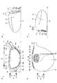
図1は、本実施の形態に係るゴルフクラブヘッド1を例示する図であり、図1(a)は正面図、図1(b)は底面図、図1(c)は左側面図、図1(d)は右側面図である。
FIG. 1 is a view illustrating a
図1では、フェース面11f側から視た図を正面図としており、ゴルフクラブヘッド1を水平面H(地面に相当)に基準のライ角θ及び基準のロフト角(図示せず)通りに接地した場合を図示している。なお、Jはホゼル部15の穴の中心軸を示している。また、矢印d1はトウ−ヒール方向(左右方向)を、矢印d2はトップ−ソール方向(上下方向)を、矢印d3はフェース−バック方向(前後方向)を示している。
In FIG. 1, a view seen from the
図1に示すゴルフクラブヘッド1は、ウッド型のゴルフクラブヘッドであって、例えばドライバであるが、ユーティリティやフェアウェイウッドであってもよい。ゴルフクラブヘッド1は、例えば、チタン合金、チタン、ステンレス、ベリリウムカッパ等の金属材料を用いて形成することができる。また、ゴルフクラブヘッド1は、複数の部品を接合して組み立てることができる。以下、ゴルフクラブヘッド1について詳説する。
A
ゴルフクラブヘッド1は、フェース部11と、クラウン部12と、ソール部13と、サイド部14と、ホゼル部15とを有する中空構造体である。なお、中空構造体の内側の面をヘッド内面、外側の面をヘッド外面と称する場合がある。
The
フェース部11は、打撃面となるフェース面11fを備えた部分である。なお、フェース部11は所定の厚みを有しており、フェース面11fはフェース部11の外面をなしている。クラウン部12は、ゴルフクラブヘッド1の上部を形成する部分である。ソール部13は、ゴルフクラブヘッド1の底部を形成する部分である。サイド部14は、クラウン部12とソール部13とを繋ぐ部分である。ホゼル部15は、シャフトと連結される部分である。
The
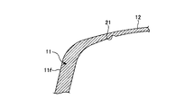
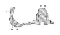
図2は、ゴルフクラブヘッド1のフェース面11fの輪郭Fと各凹部との位置関係を示す正面図である。また、図3は、ゴルフクラブヘッド1の部分拡大端面図であり、図2のA線の位置で紙面垂直方向(フェース−バック方向)に切断したフェース部11及びクラウン部12の一部を図示している。図4は、ゴルフクラブヘッド1の部分拡大端面図であり、図2のA線の位置で紙面垂直方向(フェース−バック方向)に切断したフェース部11及びソール部13の一部を図示している。
FIG. 2 is a front view showing the positional relationship between the contour F of the
Aは、図2の平面内において水平面Hと垂直であって、フェース面11fの輪郭Fをトウ−ヒール方向に半分に分割する直線である。また、Bは、図2の平面内において水平面Hと平行であってフェース面11fの輪郭Fをトップ−ソール方向に半分に分割する直線である。図2の平面内における直線Aと直線Bとの交点Cがフェース面11fの中心(フェース中心)となる。
A is a straight line that is perpendicular to the horizontal plane H in the plane of FIG. 2 and divides the contour F of the
図1〜図3を参照するに、ゴルフクラブヘッド1は、部分的にフェース面11fの輪郭Fに沿って伸びる内側凹部21を有している。なお、図2の破線Dで囲まれた部分が、内側凹部21において、フェース面11fの輪郭Fに沿って伸びていない部分である。破線Dで囲まれた部分を除く内側凹部21とフェース面11fの輪郭Fとの最小距離L1は、5mm以上15mm以下であることが好ましい。
Referring to FIGS. 1 to 3, the
内側凹部21は、図1及び図2では視認できないため破線で位置を示しているが、図3に示すように、ヘッド内面からヘッド外面側に向かって窪む溝である。内側凹部21は、トウ側の端部である内側凹部トウ端21a、及びヒール側の端部である内側凹部ヒール端21bを有している。内側凹部トウ端21aはサイド部14の内面(ヘッド内面の一部)に位置し、内側凹部ヒール端21bはフェース部11の背面(ヘッド内面の一部)に位置している。
Since the
なお、内側凹部21は、連続する1本の溝である必要はなく、必要に応じ、複数の部分に分割されてもよい。例えば、内側凹部21を独立した2本の凹部から構成してもよい。
The
図1及び図2を参照するに、ゴルフクラブヘッド1は、フェース面11fの輪郭に沿って伸びる外側トウ凹部22及び外側ヒール凹部23を備えている。外側トウ凹部22は、トウ側に配置された、ヘッド外面からヘッド内面側に向かって窪む溝である。外側ヒール凹部23は、ヒール側に配置された、ヘッド外面からヘッド内面側に向かって窪む溝である。
1 and 2, the
このように、ゴルフクラブヘッド1では、クラウン部12側及びサイド部14側の一部に内側凹部21を設け、サイド部14側に外側トウ凹部22、及び外側ヒール凹部23を設けているが、図2の直線Aのソール部13側において、フェース面11fの輪郭Fに沿う凹部はない。
As described above, in the
外側トウ凹部22とフェース面11fの輪郭Fとの最小距離L2は、2mm以上10mm以下であることが好ましい。また、外側ヒール凹部23とフェース面11fの輪郭Fとの最小距離L3は、2mm以上10mm以下であることが好ましい。なお、外側トウ凹部22及び外側ヒール凹部23を含めて、単に外側凹部と称する場合がある。
Minimum distance L 2 between the contour F of the outer tows recess 22 and the
外側トウ凹部22及び外側ヒール凹部23は、ゴルフクラブヘッド1を基準のライ角及びロフト角で接地した場合に、上方(クラウン部12側)から視認できない位置に配置されている。これにより、ゴルフクラブヘッド1の使用者がアドレスした際に、外側トウ凹部22及び外側ヒール凹部23が視認されないため、使用者は違和感なくアドレスすることができる。
The outer toe
外側トウ凹部22は、トップ側の端部である外側トウ凹部上端22a、及びソール側の端部である外側トウ凹部下端22bを有している。同様に、外側ヒール凹部23は、トップ側の端部である外側ヒール凹部上端23a、及びソール側の端部である外側ヒール凹部下端23bを有している。
The
外側トウ凹部上端22aは、内側凹部トウ端21aの近傍に位置している。具体的には、外側トウ凹部上端22aと内側凹部トウ端21aとの最小距離L4が、3mm以上30mm以下となるよう両者が配置されている。また、外側ヒール凹部上端23aは、内側凹部ヒール端21bの近傍に位置している。具体的には、外側ヒール凹部上端23aと内側凹部ヒール端21bとの最小距離L5が、3mm以上30mm以下となるよう両者が配置されている。
The outer toe recess
このように、ゴルフクラブヘッド1では、内側凹部21に内側凹部トウ端21a及び内側凹部ヒール端21bを設けている。これにより、外側トウ凹部22の外側トウ凹部上端22a及び外側ヒール凹部23の外側ヒール凹部上端23aと内側凹部21との距離を短くでき、トウ側〜クラウン側〜ヒール側にわたり、凹部でフェース面11fの輪郭Fの周囲の大部分を囲むことができる。
Thus, in the
内側凹部21は、インパクト時にフェース部11のクラウン部12側及びサイド部14側の一部を撓ませる役割がある。また、外側トウ凹部22及び外側ヒール凹部23は、インパクト時にフェース部11のサイド部14側の一部を撓ませる役割がある。
The inner
上記のようにクラウン部12側及びサイド部14側の一部に内側凹部21を設け、サイド部14側に外側トウ凹部22、及び外側ヒール凹部23を設けることにより、インパクト時にフェース部11のクラウン部12側及びサイド部14側を大きく撓ませることができる。その結果、フェース面11fでボールを打撃した際の打ち出し角度を高くできると共に、オフセンターで打撃した場合の反発力を向上できる。
As described above, the inner
なお、図1では、外側トウ凹部22及び外側ヒール凹部23のそれぞれの全体がフェース面11fの輪郭Fに沿って伸びている。しかし、これには限定されず、外側トウ凹部22及び外側ヒール凹部23の一方または双方は、内側凹部21における破線Dで囲まれた部分のように、フェース面11fの輪郭Fに沿って伸びていない部分を含んでもよい。
In FIG. 1, the entire
図1及び図4を参照するに、ソール部13にはヘッド重量調整用部品であるウエイト30を取り付け可能な取り付け部24が配置されている。図1(b)では、取り付け部24にウエイト30を取り付けた状態を例示しているが、ウエイト30は着脱可能であって、必要に応じて必要なウエイトを適宜取り付けることができる(つまり、ウエイト30はゴルフクラブヘッド1の必須の構成要素ではない)。ウエイト30を用いたウエイト調整により、ゴルフクラブヘッド1の重心位置の調整が可能となる。
Referring to FIGS. 1 and 4, a mounting
ソール部13において、取り付け部24の周辺領域には、ヘッド外面から窪むソール凹部13xが設けられている。ソール凹部13xには、底面視において、取り付け部24を挟んで対向して配置された、ヘッド外面から突起する細長状の外側リブ25及び26が設けられている。外側リブ25及び26は、底面視において、バック側からフェース側にいくに従って両者の間隔が徐々に狭くなるように傾斜している。
In the
ソール部13には、ヘッド内面から突起する内側リブ27が配置されている。内側リブ27は、底面視において、外側リブ25と外側リブ26のトウ−ヒール方向の間(略中間部)であって、フェース面11f寄りに配置されている。なお、図1(a)及び図1(b)では内側リブ27は視認できないため、破線で位置を示しているが、図4に示すように、内側リブ27は、ヘッド内面から内側に突起する突起部(破線より内側が内側リブ27)である。また、図4に示すように、取り付け部24は、ウエイト30を取り付けるためのネジ穴である。
An
外側リブ25及び26並びに内側リブ27は、トウ−ヒール方向において、外側トウ凹部22の外側トウ凹部下端22bと、外側ヒール凹部23の外側ヒール凹部下端23bとの間に配置されている。
The
このように、ソール部13に外側リブ25及び26並びに内側リブ27を設けることにより、ソール部13側の剛性を更に高めることができる。その結果、内側凹部21、外側トウ凹部22、及び外側ヒール凹部23による打ち出し角度を高くする効果や、オフセンターで打撃した場合の反発力を向上する効果を更に高めることができる。
Thus, by providing the
また、ソール凹部13xに外側リブ25及び26を設けることにより、外側リブ25及び26がヘッド外面から突起しないため、安定したアドレスが可能となる。
Further, by providing the
以上、好ましい実施の形態について詳説したが、上述した実施の形態に制限されることはなく、特許請求の範囲に記載された範囲を逸脱することなく、上述した実施の形態に種々の変形及び置換を加えることができる。 The preferred embodiment has been described in detail above. However, the present invention is not limited to the above-described embodiment, and various modifications and replacements are made to the above-described embodiment without departing from the scope described in the claims. Can be added.
例えば、ホゼル部を、シャフト先端に固着されるスリーブを着脱可能な構成としてもよい。スリーブを用いることで、容易にシャフト交換することができる。また、スリーブ内に設けられたシャフト挿入穴の軸をホゼル部の穴の中心軸に対して傾けて形成することも可能である。この場合、スリーブを軸方向に回転させ、ホゼル部との嵌合位置を変えることで、ライ角やロフト角を可変することができる。 For example, the hosel portion may be configured to be detachable from a sleeve fixed to the shaft tip. By using a sleeve, the shaft can be easily replaced. It is also possible to form the shaft insertion hole provided in the sleeve inclined with respect to the center axis of the hosel hole. In this case, the lie angle and the loft angle can be varied by rotating the sleeve in the axial direction and changing the fitting position with the hosel part.
1 ゴルフクラブヘッド
11 フェース部
11f フェース面
12 クラウン部
13 ソール部
13x ソール凹部
14 サイド部
15 ホゼル部
21 内側凹部
21a 内側凹部トウ端
21b 内側凹部ヒール端
22 外側トウ凹部
22a 外側トウ凹部上端
22b 外側トウ凹部下端
23 外側ヒール凹部
23a 外側ヒール凹部上端
23b 外側ヒール凹部下端
24 取り付け部
25、26 外側リブ
27 内側リブ
30 ウエイト
DESCRIPTION OF
Claims (10)
ヘッド内面から窪み、部分的に前記フェース面の輪郭に沿って伸びる内側凹部と、
ヘッド外面から窪み、部分的に前記フェース面の輪郭に沿って伸びる外側凹部と、を有することを特徴とするゴルフクラブヘッド。 A golf club head having a face portion having a face surface as a striking surface and a sole portion forming a bottom portion,
An inner recess that is recessed from the inner surface of the head and partially extends along the contour of the face surface;
A golf club head, comprising: an outer recess recessed from an outer surface of the head and partially extending along the contour of the face surface.
前記内側凹部ヒール端は、前記フェース部の背面に位置することを特徴とする請求項1乃至4の何れか一項に記載のゴルフクラブヘッド。 The inner recess has an inner recess toe end that is an end on the toe side, and an inner recess heel end that is an end on the heel side,
5. The golf club head according to claim 1, wherein the inner recessed heel end is located on a back surface of the face portion.
前記外側トウ凹部は、トップ側の端部である外側トウ凹部上端、及びソール側の端部である外側トウ凹部下端を有し、
前記外側ヒール凹部は、トップ側の端部である外側ヒール凹部上端、及びソール側の端部である外側ヒール凹部下端を有し、
前記内側凹部トウ端は、前記外側トウ凹部上端の近傍に位置し、
前記内側凹部ヒール端は、前記外側ヒール凹部上端の近傍に位置することを特徴とする請求項3に記載のゴルフクラブヘッド。 The inner recess has an inner recess toe end that is an end on the toe side, and an inner recess heel end that is an end on the heel side,
The outer toe recess has an upper end of an outer toe recess that is an end on the top side and a lower end of an outer toe recess that is an end on the sole side,
The outer heel recess has an outer heel recess upper end that is an end on the top side and an outer heel recess lower end that is an end on the sole side,
The inner recess toe end is located in the vicinity of the outer toe recess upper end,
The golf club head according to claim 3, wherein the inner recessed heel end is positioned in the vicinity of the outer heel recessed upper end.
前記リブは、トウ−ヒール方向において、前記複数の凹部の間に配置されていることを特徴とする請求項7に記載のゴルフクラブヘッド。 The outer recess includes a plurality of recesses,
The golf club head according to claim 7, wherein the rib is disposed between the plurality of recesses in a toe-heel direction.
前記外側リブは、前記ソール凹部に配置されていることを特徴とする請求項9に記載のゴルフクラブヘッド。 The sole portion is provided with a sole recess recessed from the outer surface of the head,
The golf club head according to claim 9, wherein the outer rib is disposed in the sole recess.
Priority Applications (2)
| Application Number | Priority Date | Filing Date | Title |
|---|---|---|---|
| JP2016084452A JP6749132B2 (en) | 2016-04-20 | 2016-04-20 | Golf club head |
| US15/460,586 US9993701B2 (en) | 2016-04-20 | 2017-03-16 | Golf club head |
Applications Claiming Priority (1)
| Application Number | Priority Date | Filing Date | Title |
|---|---|---|---|
| JP2016084452A JP6749132B2 (en) | 2016-04-20 | 2016-04-20 | Golf club head |
Publications (2)
| Publication Number | Publication Date |
|---|---|
| JP2017192550A true JP2017192550A (en) | 2017-10-26 |
| JP6749132B2 JP6749132B2 (en) | 2020-09-02 |
Family
ID=60088375
Family Applications (1)
| Application Number | Title | Priority Date | Filing Date |
|---|---|---|---|
| JP2016084452A Active JP6749132B2 (en) | 2016-04-20 | 2016-04-20 | Golf club head |
Country Status (2)
| Country | Link |
|---|---|
| US (1) | US9993701B2 (en) |
| JP (1) | JP6749132B2 (en) |
Cited By (1)
| Publication number | Priority date | Publication date | Assignee | Title |
|---|---|---|---|---|
| US20230124924A1 (en) * | 2013-03-04 | 2023-04-20 | Karsten Manufacturing Corporation | Club head with sole mass element and related method |
Families Citing this family (1)
| Publication number | Priority date | Publication date | Assignee | Title |
|---|---|---|---|---|
| JP7472542B2 (en) * | 2020-02-28 | 2024-04-23 | 住友ゴム工業株式会社 | Golf Club Head |
Citations (6)
| Publication number | Priority date | Publication date | Assignee | Title |
|---|---|---|---|---|
| JP2002052099A (en) * | 2000-08-04 | 2002-02-19 | Daiwa Seiko Inc | Golf club head |
| US6348013B1 (en) * | 1999-12-30 | 2002-02-19 | Callaway Golf Company | Complaint face golf club |
| US20070049417A1 (en) * | 2005-08-31 | 2007-03-01 | Shear David A | Metal wood club |
| US20080132355A1 (en) * | 2006-11-30 | 2008-06-05 | Taylor Made Golf Company | Golf club head having ribs |
| JP2014027973A (en) * | 2012-07-31 | 2014-02-13 | Dunlop Sports Co Ltd | Golf club head |
| US20150094161A1 (en) * | 2013-10-01 | 2015-04-02 | Karsten Manufactuirng Corporation | Golf club heads with trench features and related methods |
Family Cites Families (33)
| Publication number | Priority date | Publication date | Assignee | Title |
|---|---|---|---|---|
| JPH0793956B2 (en) * | 1990-11-15 | 1995-10-11 | 株式会社大沢商会 | Golf club head |
| US5301946A (en) * | 1992-08-05 | 1994-04-12 | Callaway Golf Company | Iron golf club head with dual intersecting recesses and associated slits |
| US5626530A (en) * | 1992-08-05 | 1997-05-06 | Callaway Golf Company | Golf club head with sole bevel indicia |
| US5472203A (en) * | 1992-08-05 | 1995-12-05 | Callaway Golf Company | Iron golf club head with dual intersecting recesses |
| JPH06190088A (en) * | 1992-12-25 | 1994-07-12 | Maruman Golf Corp | Golf club head |
| JPH10263118A (en) * | 1997-03-24 | 1998-10-06 | Asics Corp | Golf club head |
| JP3469758B2 (en) * | 1997-10-14 | 2003-11-25 | ダイワ精工株式会社 | Golf club |
| JP2000317018A (en) | 1999-05-07 | 2000-11-21 | Bridgestone Sports Co Ltd | Wood club head |
| JP3641173B2 (en) * | 1999-11-02 | 2005-04-20 | 住友ゴム工業株式会社 | Golf club head |
| JP4460138B2 (en) * | 2000-10-20 | 2010-05-12 | Sriスポーツ株式会社 | Golf club head |
| JP2002239040A (en) * | 2001-02-20 | 2002-08-27 | Sumitomo Rubber Ind Ltd | Golf club head |
| JP2003024481A (en) * | 2001-07-12 | 2003-01-28 | Yokohama Rubber Co Ltd:The | Golf club head |
| US8235844B2 (en) * | 2010-06-01 | 2012-08-07 | Adams Golf Ip, Lp | Hollow golf club head |
| US7294064B2 (en) * | 2003-03-31 | 2007-11-13 | K.K Endo Seisakusho | Golf club |
| JP2004351054A (en) * | 2003-05-30 | 2004-12-16 | Daiwa Seiko Inc | Metal hollow golf club head |
| JP4292040B2 (en) | 2003-08-28 | 2009-07-08 | ダイワ精工株式会社 | Golf club head |
| JP2006094965A (en) * | 2004-09-28 | 2006-04-13 | Daiwa Seiko Inc | Golf club head |
| JP2005193069A (en) * | 2005-03-08 | 2005-07-21 | Maruman Kk | High resilience golf club head having a thin portion near the face portion |
| US7582024B2 (en) | 2005-08-31 | 2009-09-01 | Acushnet Company | Metal wood club |
| JP2007136069A (en) * | 2005-11-22 | 2007-06-07 | Sri Sports Ltd | Golf club head |
| US7585233B2 (en) | 2006-05-26 | 2009-09-08 | Roger Cleveland Golf Co., Inc. | Golf club head |
| JP5714793B2 (en) * | 2008-10-07 | 2015-05-07 | ブリヂストンスポーツ株式会社 | Golf club head |
| EP2456529B1 (en) | 2009-07-24 | 2016-01-06 | NIKE Innovate C.V. | Golf club head or other ball striking device having impact-influence body features |
| US8632419B2 (en) | 2010-03-05 | 2014-01-21 | Callaway Golf Company | Golf club head |
| US8827831B2 (en) | 2010-06-01 | 2014-09-09 | Taylor Made Golf Company, Inc. | Golf club head having a stress reducing feature |
| US8821312B2 (en) * | 2010-06-01 | 2014-09-02 | Taylor Made Golf Company, Inc. | Golf club head having a stress reducing feature with aperture |
| JP5204826B2 (en) * | 2010-09-30 | 2013-06-05 | ダンロップスポーツ株式会社 | Golf club head |
| US8579728B2 (en) | 2011-09-12 | 2013-11-12 | Karsten Manufacturing Corporation | Golf club heads with weight redistribution channels and related methods |
| US8403771B1 (en) * | 2011-12-21 | 2013-03-26 | Callaway Gold Company | Golf club head |
| US8858360B2 (en) * | 2011-12-21 | 2014-10-14 | Callaway Golf Company | Golf club head |
| JP5629929B2 (en) * | 2012-02-15 | 2014-11-26 | テーラー メイド ゴルフ カンパニー,インク. | Golf club head having stress reducing structure including hollow portion |
| US9079079B2 (en) | 2012-09-19 | 2015-07-14 | Karsten Manufacturing Corporation | Club head with deflection mechanism and related methods |
| JP6149380B2 (en) * | 2012-10-31 | 2017-06-21 | 横浜ゴム株式会社 | Golf club head |
-
2016
- 2016-04-20 JP JP2016084452A patent/JP6749132B2/en active Active
-
2017
- 2017-03-16 US US15/460,586 patent/US9993701B2/en active Active
Patent Citations (6)
| Publication number | Priority date | Publication date | Assignee | Title |
|---|---|---|---|---|
| US6348013B1 (en) * | 1999-12-30 | 2002-02-19 | Callaway Golf Company | Complaint face golf club |
| JP2002052099A (en) * | 2000-08-04 | 2002-02-19 | Daiwa Seiko Inc | Golf club head |
| US20070049417A1 (en) * | 2005-08-31 | 2007-03-01 | Shear David A | Metal wood club |
| US20080132355A1 (en) * | 2006-11-30 | 2008-06-05 | Taylor Made Golf Company | Golf club head having ribs |
| JP2014027973A (en) * | 2012-07-31 | 2014-02-13 | Dunlop Sports Co Ltd | Golf club head |
| US20150094161A1 (en) * | 2013-10-01 | 2015-04-02 | Karsten Manufactuirng Corporation | Golf club heads with trench features and related methods |
Cited By (2)
| Publication number | Priority date | Publication date | Assignee | Title |
|---|---|---|---|---|
| US20230124924A1 (en) * | 2013-03-04 | 2023-04-20 | Karsten Manufacturing Corporation | Club head with sole mass element and related method |
| US12102898B2 (en) * | 2013-03-04 | 2024-10-01 | Karsten Manufacturing Corporation | Club head with sole mass element and related method |
Also Published As
| Publication number | Publication date |
|---|---|
| US20170304689A1 (en) | 2017-10-26 |
| JP6749132B2 (en) | 2020-09-02 |
| US9993701B2 (en) | 2018-06-12 |
Similar Documents
| Publication | Publication Date | Title |
|---|---|---|
| JP5989509B2 (en) | Golf club head and golf club | |
| JP4482936B2 (en) | Iron type golf club | |
| JP5638847B2 (en) | Golf club head | |
| JP6363406B2 (en) | Golf club head | |
| JP2005160947A (en) | Golf club head | |
| JP2001204863A (en) | Iron golf club head | |
| JP2010234108A (en) | Golf club head | |
| JP2017038664A (en) | Golf club head | |
| JP5359782B2 (en) | Golf club head | |
| JP6827308B2 (en) | Golf club head | |
| JP2017192550A (en) | Golf club head | |
| JP6790532B2 (en) | Golf club head | |
| JP5325826B2 (en) | Golf club | |
| JP2011206243A (en) | Golf club | |
| JP7419859B2 (en) | golf club head | |
| JP6827310B2 (en) | Golf club head | |
| JP6661962B2 (en) | Golf club head | |
| JP5447914B2 (en) | Wood type golf club head and wood type golf club | |
| JP2009082291A (en) | Hollow golf club head | |
| JP2017189293A (en) | Golf club head | |
| JP5779497B2 (en) | Golf club head | |
| JP2006305170A (en) | Golf club | |
| JP2018093959A (en) | Golf club head | |
| JP6000393B1 (en) | Wood type golf club head and wood type golf club | |
| JP6993776B2 (en) | Golf club head |
Legal Events
| Date | Code | Title | Description |
|---|---|---|---|
| A621 | Written request for application examination |
Free format text: JAPANESE INTERMEDIATE CODE: A621 Effective date: 20190314 |
|
| A977 | Report on retrieval |
Free format text: JAPANESE INTERMEDIATE CODE: A971007 Effective date: 20191218 |
|
| A131 | Notification of reasons for refusal |
Free format text: JAPANESE INTERMEDIATE CODE: A131 Effective date: 20200128 |
|
| A521 | Request for written amendment filed |
Free format text: JAPANESE INTERMEDIATE CODE: A523 Effective date: 20200326 |
|
| TRDD | Decision of grant or rejection written | ||
| A01 | Written decision to grant a patent or to grant a registration (utility model) |
Free format text: JAPANESE INTERMEDIATE CODE: A01 Effective date: 20200804 |
|
| A61 | First payment of annual fees (during grant procedure) |
Free format text: JAPANESE INTERMEDIATE CODE: A61 Effective date: 20200811 |
|
| R150 | Certificate of patent or registration of utility model |
Ref document number: 6749132 Country of ref document: JP Free format text: JAPANESE INTERMEDIATE CODE: R150 |
|
| R250 | Receipt of annual fees |
Free format text: JAPANESE INTERMEDIATE CODE: R250 |
|
| R250 | Receipt of annual fees |
Free format text: JAPANESE INTERMEDIATE CODE: R250 |
|
| R250 | Receipt of annual fees |
Free format text: JAPANESE INTERMEDIATE CODE: R250 |