JP2017192541A - Air mattress and air mattress device - Google Patents
Air mattress and air mattress device Download PDFInfo
- Publication number
- JP2017192541A JP2017192541A JP2016084310A JP2016084310A JP2017192541A JP 2017192541 A JP2017192541 A JP 2017192541A JP 2016084310 A JP2016084310 A JP 2016084310A JP 2016084310 A JP2016084310 A JP 2016084310A JP 2017192541 A JP2017192541 A JP 2017192541A
- Authority
- JP
- Japan
- Prior art keywords
- air
- mat member
- air mattress
- air mat
- mattress
- Prior art date
- Legal status (The legal status is an assumption and is not a legal conclusion. Google has not performed a legal analysis and makes no representation as to the accuracy of the status listed.)
- Granted
Links
Images


Landscapes
- Mattresses And Other Support Structures For Chairs And Beds (AREA)
- Invalid Beds And Related Equipment (AREA)
Abstract
【課題】使用中の側端部の反り上がりが抑制されて寝心地に優れると共に、床ずれを低減でき、さらに部分的な交換補修が容易なエアーマットレス及びエアーマットレス装置を提供する。【解決手段】エアーマットレスは、第1の表層シートと第1の中間シートとを積層し、外周部を封止して構成された空気を充填可能な第1のエアーマット部材と、第2の表層シートと第2の中間シートとを積層し、外周部を封止して構成された空気を充填可能な第2のエアーマット部材と、第1のエアーマット部材と第2のエアーマット部材とを積層した状態で各エアーマット部材の周端部に備えられた連結用帯のうち、少なくとも両サイドの連結用帯を互いに連結する連結手段とを備え、連結手段は、第1のエアーマット部材及び第2のエアーマット部材の外周部を縫着する紐部材から構成されている。【選択図】図1PROBLEM TO BE SOLVED: To provide an air mattress and an air mattress device in which warp of a side end portion during use is suppressed, which is excellent in sleeping comfort, can reduce a bed slip, and is easy to partially replace and repair. An air mattress comprises a first surface layer sheet and a first intermediate sheet laminated, and an air-fillable first air mat member configured by sealing an outer peripheral portion, and a second air mattress. A second air mat member, which is formed by laminating a surface layer sheet and a second intermediate sheet, and is configured by sealing an outer peripheral portion, and which can be filled with air, a first air mat member, and a second air mat member. Among the connecting bands provided at the peripheral end portion of each air mat member in a laminated state, there is provided a connecting means for connecting at least the connecting bands on both sides to each other, and the connecting means is the first air mat member. And a string member for sewing the outer peripheral portion of the second air mat member. [Selection diagram] Figure 1
Description
本発明は、寝具や床ずれ(褥瘡)の予防又は軽減、及び床ずれの治療に用いることのできるエアーマットレス及びエアーマットレス装置に関し、特に静置型のエアーマットレス及びエアーマットレス装置に関する。 The present invention relates to an air mattress and an air mattress device that can be used for the prevention or reduction of bedding and bedsores (decubitus) and the treatment of bedsores, and more particularly to a static air mattress and an air mattress device.
従来から、内部に空気などの気体が充填されたエアーマットレスが広く用いられている。これらのエアーマットレスは体圧分散に優れるという特徴があり、それゆえ、医療機関や介護・福祉施設等においては、長時間横臥状態にある使用者に対し、床ずれの発生を抑制する目的で使用される。一般的にエアーマットレスは、複数の空気室(エアセルともいう)を交互に膨張収縮させる圧切替型と、単数または複数のエアセルに気体を充填し封止する、もしくは気体充填後にエアセルの圧力を調整する、いわゆる静置型とに大別され、床ずれ防止等の介護用途においては、圧切替型エアーマットレスが主流になっている。しかし近年、使用者の身体を低圧で保持するだけで優れた寝心地と床ずれ防止効果が得られる静置型のエアーマットレスが注目されている。しかしながら、このような静置型エアーマットレスは、内圧を低圧とした場合、使用者の姿勢や状態により体重が集中した部分に底づきが生じてしまうおそれがある。この底づきとは、使用者の骨突出部位がマットレス下の床面にあたっている状態をいい、寝心地が悪いだけでなく、床ずれを発生させたり、悪化させる原因ともなる。 Conventionally, air mattresses that are filled with a gas such as air have been widely used. These air mattresses are characterized by excellent body pressure dispersion. Therefore, they are used in medical institutions and nursing / welfare facilities for the purpose of suppressing the occurrence of bedsores for users who are lying for a long time. The In general, an air mattress is a pressure switching type that alternately expands and contracts a plurality of air chambers (also referred to as air cells), and one or a plurality of air cells are filled and sealed, or the pressure of the air cells is adjusted after gas filling. The so-called stationary type is roughly divided, and the pressure-switching type air mattress is mainly used in nursing applications such as prevention of bed slipping. However, in recent years, static air mattresses have been attracting attention, which can provide an excellent sleeping comfort and a bed slip prevention effect simply by holding the user's body at a low pressure. However, in such a stationary air mattress, when the internal pressure is set to a low pressure, there is a possibility that the portion where the weight is concentrated depending on the posture and state of the user may bottom out. This bottoming refers to a state in which the user's bone protruding part is in contact with the floor surface under the mattress, which not only causes poor sleeping comfort but also causes or worsens bed slippage.
そこで、上述のような問題を解消するべく、低圧でも底づきを防止できるエアーマットレスとして、エアセルを複層に積層し、周囲を溶着したエアーマットレスが提案されている(一例として、特許文献1、2参照)。
Then, in order to solve the above problems, as an air mattress capable of preventing bottoming even at low pressure, an air mattress in which air cells are stacked in multiple layers and the periphery is welded has been proposed (for example,
例えば、特許文献1には、上側シートと下側シートとの間を仕切によって遮断して、上部空気層と下部空気層を形成すると共に、上側シートと仕切を溶着して上部空気層に複数の山部と谷部を形成すると共に、上部空気層の谷部の下に下部空気層の山部が形成されるように下側シートと仕切を溶着して複数の山部と谷部を形成したエアーマットであって、仕切が上側仕切シートと下側仕切シートの2枚のシートからなり、上側シートと上側仕切シートとが溶着され、下側シートと下側仕切シートとが溶着され、さらにこれらの周囲が重ね合わせて溶着されている構造とすることによって、空気層の一部が押されて凹んでも、反り返ることがなく安定した状態を保つことができ、しかも凹んだ部分に空気がなくなることがなく底突きしないエアーマットが開示されている。
For example, in
また、特許文献2には、重ね合わされ、周囲が接着され密封状態とされた可撓性を有する4枚の第1ないし第4シートから形成され、該第1シート及び第2シート間が適当間隔隔てた点状に接着されるとともにこの点が矩形の角となる位置に配された複数の第1接着部と、上記第2シート及び上記第3シート間を点状に接着するとともにこの点が上記矩形の中央に配置された複数の第2接着部と、上記第3シート及び第4シート間を点状に接着するとともに上記第1接着部と同じ位置に配置された複数の第3接着部とを備え、上記第1及び第2シート間に第1エアセルが、上記第2及び第3シート間に第2エアセルが、上記第3及び第4シート間に第3エアセルが構成され、底着き現象を防止した低圧のエアマットエアマットが開示されている。
Further,
しかしながら、特許文献1乃至2の何れのエアーマットレスも周囲を溶着で封止した構造のため、使用者の体重がエアーマットレス中央部にかかって内部の気体がマットレス端部に移動して内圧が高まると、溶着された周端部の変形が規制されるため、特に両側面部が反り上がる現象について改善の余地があった。このエアーマットレスの両側面部の反り上がりが生じると、仰臥位の寝姿勢において体が両側から圧迫されるため、寝心地が悪くなることがあった。また、エアセルの一部が破損した場合には、エアーマットレスを廃棄しなければならず、メンテナンス性にも課題があった。
However, since the air mattress of any of
従って、本発明は従来技術の上述した問題点を解消するものであり、本発明の目的は、使用中の側端部の反り上がりが抑制されて寝心地に優れると共に、床ずれを低減でき、さらに部分的な交換補修が容易なエアーマットレス及びエアーマットレス装置を提供することにある。 Accordingly, the present invention solves the above-mentioned problems of the prior art, and the object of the present invention is to suppress the warping of the side end portion in use and to improve the sleeping comfort and to reduce the floor slip. It is an object of the present invention to provide an air mattress and an air mattress device that can be easily replaced and repaired.
本発明の他の目的は、位置ずれを防止でき、かつ背上げ、膝上げ等が容易にできるエアーマットレス及びエアーマットレス装置を提供することにある。 Another object of the present invention is to provide an air mattress and an air mattress device that can prevent misalignment and can easily raise the back and knees.
本発明によれば、エアーマットレスは、第1の表層シートと第1の中間シートとを積層し、外周部を封止して構成された空気を充填可能な第1のエアーマット部材と、第2の表層シートと第2の中間シートとを積層し、外周部を封止して構成された空気を充填可能な第2のエアーマット部材と、第1のエアーマット部材と第2のエアーマット部材とを積層した状態で各エアーマット部材の周端部に備えられた連結用帯のうち、少なくとも両サイドの連結用帯を互いに連結する連結手段とを備え、連結手段は、第1のエアーマット部材及び第2のエアーマット部材の外周部を縫着する紐部材から構成されている。 According to the present invention, the air mattress is formed by laminating the first surface layer sheet and the first intermediate sheet, sealing the outer peripheral portion, and filling the air with the first air mat member, A second air mat member that is formed by laminating two surface layer sheets and a second intermediate sheet and sealing the outer periphery, and the first air mat member and the second air mat. A connecting means for connecting at least the connecting bands on both sides among the connecting bands provided at the peripheral end of each air mat member in a state where the members are laminated, and the connecting means includes the first air It is comprised from the string member which sews the outer peripheral part of a mat member and a 2nd air mat member.
紐部材からなる連結手段で第1のエアーマット部材と第2のエアーマット部材とを積層した状態で少なくとも両サイドの連結用帯を互いに連結することにより、使用中の側端部の反り上がりが抑制されて寝心地に優れると共に、床ずれを低減でき、さらに部分的な交換補修が容易になる。 By connecting the connecting bands on at least both sides in a state where the first air mat member and the second air mat member are laminated by the connecting means made of the string member, the side end portion in use is warped up. In addition to being suppressed and excellent in sleeping comfort, floor slip can be reduced, and partial replacement repair is facilitated.
連結手段で第1のエアーマット部材と第2のエアーマット部材とを積層した状態で構成された積層体を水平方向に複数個連結して構成され、隣接する積層体は、隣接する第1のエアーマット部材の連結用帯どうしの連結、及び隣接する第2のエアーマット部材の連結用帯どうしの連結によって互いに連結されていることが好ましい。これにより、エアセルの一部が破損した場合、エアーマットレスの一部のみを交換することができ、メンテナンス性を向上するができる。また、背上げ、膝上げ等を行う際にエアーマットレスの変形が容易になる。また、各積層体の内圧を、使用者の部位に応じてそれぞれ最適化することによって、床ずれ防止の効果がさらに向上する。 A plurality of laminated bodies configured in a state where the first air mat member and the second air mat member are laminated by the connecting means are configured to be connected in the horizontal direction, and the adjacent laminated bodies are adjacent to the adjacent first It is preferable that the air mat members are connected to each other by connecting the connecting bands of the air mat members and connecting the connecting bands of the adjacent second air mat members. Thereby, when a part of air cell breaks, only a part of air mattress can be replaced | exchanged and maintainability can be improved. Further, the air mattress can be easily deformed when raising the back, raising the knee, or the like. Further, by optimizing the internal pressure of each laminate according to the user's site, the effect of preventing bed slip is further improved.
連結手段で第1のエアーマット部材と第2のエアーマット部材とを積層した状態で構成された積層体を水平方向に複数個連結して構成され、隣接する積層体は、第1のエアーマット部材と第2のエアーマット部材との連結用帯が重ねて連結されていることが好ましい。これにより、エアセルの一部が破損した場合、エアーマットレスの一部のみを交換することができ、メンテナンス性を向上するができる。また、背上げ、膝上げ等を行う際にエアーマットレスの変形が容易になる。また、各積層体の内圧を、使用者の部位に応じてそれぞれ最適化することによって、床ずれ防止の効果がさらに向上する。 A plurality of laminated bodies constituted by laminating the first air mat member and the second air mat member by the connecting means are connected in the horizontal direction, and the adjacent laminated body is the first air mat. It is preferable that the connecting strips of the member and the second air mat member are overlapped and connected. Thereby, when a part of air cell breaks, only a part of air mattress can be replaced | exchanged and maintainability can be improved. Further, the air mattress can be easily deformed when raising the back, raising the knee, or the like. Further, by optimizing the internal pressure of each laminate according to the user's site, the effect of preventing bed slip is further improved.
両サイドの連結用帯の紐部材は内縫い構造に配置されていることも好ましい。これにより、エアーマット部材の長辺の連結部が外部に露出することなく、邪魔にならない。 It is also preferable that the string members of the connecting bands on both sides are arranged in an inner stitch structure. Thereby, the connection part of the long side of an air mat member is not exposed outside, and does not get in the way.
紐部材が伸縮性を有する樹脂又はゴム素材からなることも好ましい。これにより、柔軟性や伸び特性等によって、縫製による連結力を調整することができる。 It is also preferable that the string member is made of a stretchable resin or rubber material. Thereby, the connection force by sewing can be adjusted with a softness | flexibility, an elongation characteristic, etc.
紐部材がチューブ状であることも好ましい。これにより、使用者の体が接しやすい部分において、外力で変形し易く、寝心地を改善することができる。 It is also preferable that the string member has a tube shape. Thereby, it is easy to deform | transform with an external force in the part which a user's body touches easily, and it can improve sleeping comfort.
第1のエアーマット部材と第2のエアーマット部材とに充填された空気が互いに流通可能な少なくとも1つの連通部が設けられていることも好ましい。これにより、第1のエアーマット部材と第2のエアーマット部材とのいずれか一方に空気を充填することによりエアーマットレス全体に空気を充填することができる。 It is also preferable that at least one communication portion is provided in which the air filled in the first air mat member and the second air mat member can flow with each other. Thereby, the whole air mattress can be filled with air by filling one of the first air mat member and the second air mat member with air.
第1の表層シートと前記第1の中間シートとは、幅方向及び長さ方向に所定の間隔で配置された複数の接着部によって接着され、第2の表層シートと第2の中間シートとは、幅方向及び長さ方向に所定の間隔で配置された複数の接着部によって接着されていることも好ましい。これにより、接着部によって空気室があらかじめ区切られているため、マットレス上に折れ筋等の不均一な皺が生じ難い。それゆえ、全体的に柔らかで寝心地がよいエアーマットレスが得られる。 The first surface layer sheet and the first intermediate sheet are bonded by a plurality of adhesive portions arranged at predetermined intervals in the width direction and the length direction, and the second surface layer sheet and the second intermediate sheet are It is also preferable that these are bonded by a plurality of bonding portions arranged at predetermined intervals in the width direction and the length direction. Thereby, since the air chamber is partitioned in advance by the bonding portion, non-uniform wrinkles such as creases are unlikely to occur on the mattress. Therefore, an air mattress that is soft overall and comfortable to sleep is obtained.
第1のエアーマット部材の接着部が線状の接着筋であり、第2のエアーマット部材の接着部が線状の接着筋であり、第1のエアーマット部材の線状の接着筋は、第2のエアーマット部材の線状の接着筋と、平面視交差する位置に配置されていることも好ましい。これにより、第1の表面シートと第1の中間シート、及び第2の表層シートと第2の中間シートは複数の線状の接着筋によって接着され、第1の表面シートと第1の中間シートとの間、及び第2の表層シートと第2の中間シートとの間には空気が充填されることにより空気室が形成されている。マットレスの接着筋に使用者の体の突出部位が入り込むことがないため、体圧分散効果の小さい部分に使用者の体があたらず、床ずれの発生を防ぐことができる。また、線状の接着筋によって空気室があらかじめ区切られているため、マットレス上に折れ筋等の不均一な皺が生じ難い。それゆえ、全体的に柔らかで寝心地がよいエアーマットレスが得られる。 The adhesive part of the first air mat member is a linear adhesive line, the adhesive part of the second air mat member is a linear adhesive line, and the linear adhesive line of the first air mat member is It is also preferable that the second air mat member is disposed at a position intersecting with the linear adhesive stripe of the second air mat member in plan view. As a result, the first surface sheet and the first intermediate sheet, and the second surface layer sheet and the second intermediate sheet are bonded together by a plurality of linear adhesive stripes, and the first surface sheet and the first intermediate sheet And between the second surface sheet and the second intermediate sheet are filled with air to form an air chamber. Since the protruding portion of the user's body does not enter the mattress adhesive muscle, the user's body does not hit the portion where the body pressure dispersion effect is small, and the occurrence of bed slip can be prevented. In addition, since the air chamber is partitioned in advance by the linear adhesive streaks, non-uniform wrinkles such as creases are unlikely to occur on the mattress. Therefore, an air mattress that is soft overall and comfortable to sleep is obtained.
本発明によれば、エアーマットレス装置は、上述したいずれかのエアーマットレスと、エアーマットレスを支持する基台とを備え、基台は、エアーマットレスの下に設置された弾力性を有する敷き部材と、エアーマットレスの幅方向の両端側に配置された1対の端座部材とから構成されている。これにより、エアーマットレスが安定して基台内に保持される。エアーマットレスの幅方向の変形が端座部材により規制されるため、底付きの発生を抑制することもできる。また、端座部材が介助者の体を安定に支える部材としても機能するため、介助がしやすくなる。さらに、万一エアーマットレスから空気漏れが発生した場合でも、基台が使用者を安全に受け止めて支持することができる。 According to the present invention, an air mattress device includes any of the above-described air mattresses and a base that supports the air mattress, and the base is a flexible laying member installed under the air mattress. The air mattress includes a pair of end seat members disposed on both ends in the width direction of the air mattress. Thereby, an air mattress is stably hold | maintained in a base. Since deformation of the air mattress in the width direction is restricted by the end seat member, occurrence of bottoming can be suppressed. Further, since the end seat member functions as a member that stably supports the body of the caregiver, it is easy to assist. Furthermore, even if an air leak occurs from the air mattress, the base can safely receive and support the user.
敷き部材は、硬さの異なる複数層のクッション材からなり、下層から硬度が大きい順に積層されて構成されていることも好ましい。これにより、柔軟性を確保できると共に、エアーマットレスを介した寝姿勢の安定性も確保できる。また、万一エアーマットレスから空気漏れが発生して、基台が使用者を安全に受け止めたときに、敷き部材の柔軟性によって体圧分散性を維持しながら使用者を支持することができる。 It is also preferable that the laying member is composed of a plurality of layers of cushioning materials having different hardness, and is laminated from the lower layer in descending order of hardness. Thereby, while being able to ensure a softness | flexibility, the stability of the sleeping posture through an air mattress can also be ensured. Further, when an air leak occurs from the air mattress and the base safely receives the user, the user can be supported while maintaining the body pressure dispersibility by the flexibility of the laying member.
1対の端座部材には、エアーマットレスを固定するための紐を挿通可能な貫通穴又は切り込みが複数設けられていることも好ましい。これにより、エアーマットレスの位置ずれを防止することができる。 It is also preferable that the pair of end seat members are provided with a plurality of through holes or notches through which a string for fixing the air mattress can be inserted. Thereby, the position shift of an air mattress can be prevented.
本発明によれば、空気を充填可能な第1のエアーマット部材と第2のエアーマット部材とを積層した状態で、少なくとも外周の両側端部を互いに紐部材で縫製した連結構造とすることにより、使用中のエアーマットレスの両側面部の反り上がりが抑制されるとともに、各エアーマット部材のずれがなく、優れた寝心地を実現することができる。また、紐部材による連結を解くことによって、容易に各エアーマット部材を取り外せるため、部分的な補修・交換ができ、使用者のコスト負担を軽減できる。また、複数の空気室をそれぞれ有する、第1のエアーマット部材と第2のエアーマット部材とが積層されているため、低圧状態での底突きを防止できると共に、体圧分散効果に優れ、床ずれの発生を防ぐことができる。さらに、接着部を線状の接着筋とすることによって、マットレスの接着筋に使用者の体の突出部位が入り込むことがないため、体圧分散効果の小さい部分に使用者の体があたらず、床ずれの発生をより防ぐことができる。線状の接着筋によってマットレス上に折れ筋等の不均一な皺が生じ難い。それゆえ、全体的に柔らかで寝心地がよいエアーマットレスが得られる。また、エアーマットレス装置における基台には、エアーマットレスの幅方向の両端側に配置された1対の端座部材が備えられているため、エアーマットレスの幅方向の変形が端座部材により規制され、エアーマットレスが安定して保持されると共に底付きの発生も抑制する。また、端座部材が介助者の体を安定に支える部材としても機能するため、介助がしやすくなる。さらに、万一エアーマットレスから空気漏れが発生して、基台が使用者を安全に受け止めたときに、敷き部材の柔軟性によって体圧分散性を維持しながら使用者を支持することができる。 According to the present invention, in a state in which the first air mat member and the second air mat member that can be filled with air are laminated, at least both end portions of the outer periphery are sewn together with the string members. Further, it is possible to suppress the warping of both side surfaces of the air mattress in use and to prevent the air mat members from being displaced and to realize an excellent sleeping comfort. Moreover, since each air mat member can be easily removed by releasing the connection by the string member, partial repair and replacement can be performed, and the cost burden on the user can be reduced. In addition, since the first air mat member and the second air mat member, each having a plurality of air chambers, are laminated, it is possible to prevent bottoming out in a low pressure state, and an excellent body pressure dispersion effect. Can be prevented. In addition, by making the adhesive part a linear adhesive muscle, the protruding part of the user's body does not enter the adhesive muscle of the mattress, so the user's body does not hit the part with a small body pressure dispersion effect, The occurrence of bedsores can be further prevented. Non-uniform wrinkles such as creases are unlikely to occur on the mattress due to the linear adhesive streaks. Therefore, an air mattress that is soft overall and comfortable to sleep is obtained. Further, since the base in the air mattress device is provided with a pair of end seat members disposed on both ends in the width direction of the air mattress, deformation of the air mattress in the width direction is restricted by the end seat members. The air mattress is stably held and the occurrence of bottoming is suppressed. Further, since the end seat member functions as a member that stably supports the body of the caregiver, it is easy to assist. Further, when an air leak occurs from the air mattress and the base safely receives the user, the user can be supported while maintaining the body pressure dispersibility by the flexibility of the laying member.
以下、本発明に係るエアーマットレス及びエアーマットレス装置の実施形態を、図を参照して説明する。 Hereinafter, embodiments of an air mattress and an air mattress device according to the present invention will be described with reference to the drawings.
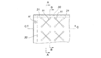
図1は本発明の第1の実施形態におけるエアーマットレス100の構成を示しており、図2はこのエアーマットレス100の部分分解状態を示している。図3はエアーマットレス100の部分拡大平面図であり、同図において、表面側(第1のエアーマット部材10側)の接着筋11を実線で、裏面側(第2のエアーマット部材20側)の接着筋21を破線で示しているが、表面側の接着筋11と裏面側の接着筋21とは、平面視交差(エアーマットレスを通常使用するように設置した際に、上から見た状態で交差)するように配置されている。図4はエアーマットレス100の構成を部分分解図で示しており、図5は図3におけるエアーマットレス100のA-A、B−B、C-C線断面及び図2の端面(Z−Z部)を示している。
FIG. 1 shows a configuration of an
図1〜図5に示すように、本実施形態におけるエアーマットレス100は、第1のエアーマット部材10と、第2のエアーマット部材20と、連結手段30と、連通部40とを備えている。
As shown in FIGS. 1 to 5, the
第1のエアーマット部材10は、第1の表層シート10aと第1の中間シート10bとを積層し、外周部を封止(溶着)して構成された、空気を充填することができるものである。第1の表層シート10aと第1の中間シート10bとは、第1のエアーマット部材10の幅方向及び長さ方向(エアーマットレス100の幅方向及び長さ方向に相当)に所定の間隔で配置された複数の線状の接着筋11によって接着されている。即ち、第1の表層シート10aと第1の中間シート10bとの間に複数の互いに連通された空気セル部を有する空気室101が形成されている。そして、第1のエアーマット部材10の周端部には、後述する第2のエアーマット部材20との連結が行われる連結用帯Sが備えられている。第1の中間シート10bには、少なくとも1つの連通孔が設けられている。この連通孔には、連通部40の一部となる接続アダプタ41が設けられている。この接続アダプタ41は第2の中間シート20bの接続アダプタ42と連結可能に構成されている。
The first
第2のエアーマット部材20は、第2の表層シート20aと第2の中間シート20bとを積層し、外周部を封止(接着)して構成された、空気を充填することができるものである。第2の表層シート20aと第2の中間シート20bとは、第2のエアーマット部材20の幅方向及び長さ方向(エアーマットレス100の幅方向及び長さ方向に相当)に所定の間隔で配置された複数の線状の接着筋21によって接着されている。第2の表層シート20aと第2の中間シート20bとの間に複数の互いに連通された空気セル部を有する空気室102が形成されている。そして、第2のエアーマット部材20の周端部には、第1のエアーマット部材10との連結が行われる連結用帯Sが備えられている。また、第2の中間シート20bには、少なくとも1つの連通孔が設けられている。この連結孔には、連通部40の一部となる接続アダプタ42が設けられている。この接続アダプタ42は第1の中間シート20aの接続アダプタ41と連結可能に構成されている。また、第2の中間シート20bには、給排気口23が設けられている。給排気口23には、給排気管P1を接続可能に構成されている(図8参照)。上述の接着とは、接着剤によるものや溶着など公知の方法を含むものである。
The second
また、第1の表層シート10aと第1の中間シート10bとを接着する線状の接着筋11は、第2の表層シート20aと第2の中間シート20bとを接着する線状の接着筋21と、平面視交差する位置に配置されている。
Moreover, the
また、線状の接着筋11及び21の端部が円弧状であることが好ましい。これにより、接着筋11及び21の端部にかかる応力が好適に分散され、接着筋11及び21の端部と表層シート及び中間との境界部分の破損を防止することができる。また、本実施形態においては、接着筋11及び21は、その端部側が徐々に太軸となる綿棒形状に形成されており、端部が大きな応力にも対応できるように設計されている。線状の接着筋11及び21の長さは、特に限定されず、接着筋の配置パターンに応じて適宜設定できる。
Moreover, it is preferable that the edge part of the linear
第1のエアーマット部材10において、第1の表層シート10aと第1の中間シート10bとを接着する表面側の接着筋11を上述のように形成することにより、エアーマットレス100に使用者が横たわる等して荷重が加えられた際、空気室101の空気セル部は押しつぶされて変形するところ、その空気セル部を形成する線状の接着筋11に沿って、接着筋11の周縁近傍の第1の表層シート10aが立ち上るため、線状の接着筋11は内部に入り込んで第1の表層シート10aの表面上には表れなくなるか、第1の表層シート10a上に表れる接着筋11の接着幅は細く狭められる。また、線状の接着筋11によって空気セル部が形成されているため、使用時に空気室101の空気セル部が押しつぶされた場合においても、接着筋11に沿って空気室101が変形するのみであり、不均一な硬い折れ筋等の皺は生じ難い。それゆえ、エアーマットレス100の接着筋11に使用者の体の突出部位が入り込み難く、接着硬質部に使用者の体があたらないため、床ずれが発生することを防ぐことができる。第2のエアーマット部材20においても同様である。なお、本実施形態において第1の表層シート10aと第1の中間シート10bとを接着する接着部及び、第2の表層シート20aと第2の中間シート20bとを接着する接着部は、上述したように線状の接着筋11及び21として構成され、平面視交差する位置に配置されているが、適当な空気室を形成できるような接着パターンであればよく、接着部の形状及び配置は上述の形状及び配置に限定されない。
In the first
連結手段30は、第1のエアーマット部材10と第2のエアーマット部材20とを積層した状態で外周部を互いに連結するものであり、第1のエアーマット部材10及び第2のエアーマット部材20の外辺にある縫い代(連結用帯S)を縫着する紐部材と、この紐部材を通すための孔であって、所定の間隔で連結用帯Sに設けられた縫合孔とから構成されている。連結手段30をこのような構成とすることで、使用者の体重でエアーマットレス100の外周連結部に気体が移動して内圧が高くなったときに、連結手段30が適度に変形して内圧による応力を緩和することによって、エアーマットレス100の周端部の反り上がりを抑制することができるのである。なお、縫合孔を設けずに、連結用帯Sに縫い針と紐部材とを使って縫合してもよい。縫合孔を設けた場合には、縫合作業が容易となり生産性に優れると共に、縫合部分に応力が集中した場合の連結用帯Sの破損がし難くなるので好ましい。また、縫合孔の径を紐部材の径よりも大きくすることで、紐部材を軸として連結用帯Sが滑りやすくなり、連結部に掛かる応力を分散しつつ連結用帯Sが変形できるため、連結部周辺での応力による皺の発生を低減できる効果もある。
The connecting means 30 connects the outer peripheral portions to each other in a state where the first
本実施形態においては、この連結手段30により連結されたエアーマットレス100の長辺における連結部分、すなわち連結用帯Sは、積層された第1のエアーマット部材10と第2のエアーマット部材20との間に位置するように、内縫いした構成とし、エアーマットレス100の短辺における連結部分(連結用帯S)は、外縫いした構成とした例であるが、全辺を内縫い又は外縫いとしてもよい。
In the present embodiment, the connecting portion on the long side of the
連結手段30で連結用帯Sを内縫いとすると、積層された第1のエアーマット部材10と第2のエアーマット部材20との間に連結用帯Sからなる縫い代が格納されるため、外観に優れると共に、使用者や介助者、ベッドのサイドレール等と連結手段30との接触がなく、連結手段30の破損リスクを回避できるため、特にエアーマットレス100の長辺部の結合手段として好ましい。
If the connecting
また、本実施形態においては、連結用帯S及び連結手段30はエアーマットレス100の全周(全辺)に設けているが、少なくとも長辺に設ければよく、短辺側を連結せずに開口した構造としてもよい。連結用帯Sは、エアーマット部材の製造において、第1の表層シート10aと第1の中間シート10bとを積層し、外周部を接着によって封止するときの接着代(しろ)として連結用帯Sを形成してもよいし、接着の幅を広く形成した接着部を連結用帯Sとしてもよい。また、第1の表層シート10aと第1の中間シート10bとを積層し、外周部を接着によって封止した後または同時に、連結用帯Sとなる別の部品を接着して連結用帯Sを形成してもよい。
Moreover, in this embodiment, although the connection belt | band | zone S and the connection means 30 are provided in the perimeter (all sides) of the
紐部材による連結用帯Sの縫製は、公知の縫い方を採用できるが、生産性と分解時の紐抜きの容易性の観点から、並縫い(波縫い)が好ましい。紐部材による縫い目の間隔と縫いの締め付け強さで、第1のエアーマット部材10と第2のエアーマット部材20との連結力を調整できる。例えば、縫い目の間隔は、10〜100mmが好ましく、20〜70mmがより好ましく、30〜50mmがさらに好ましい。縫い目の間隔が10mm未満であると、連結力が強くなりすぎて、使用時のエアーマットレス側辺部の反り上がりの抑制効果が不十分になり、100mmを超えると、使用時に連結部分(縫製部分)に応力が集中するため連結部分が破損しやすくなったり、連結力が不十分となって第1のエアーマット部材10と第2のエアーマット部材20とがお互いに位置ずれする場合があるため、上述の範囲とするのが好ましい。
For the sewing of the connecting band S by the string member, a publicly known sewing method can be adopted, but from the viewpoint of productivity and ease of string removal at the time of disassembly, side-by-side stitching (wave stitching) is preferable. The connecting force between the first
また、縫製の締め付けは、強すぎると連結力が強くなりすぎて、使用時のエアーマットレス側辺部の反り上がりの抑制効果が不十分になり、逆に弱すぎると連結力が不十分となって第1のエアーマット部材10と第2のエアーマット部材20とがお互いに位置ずれする場合があるため、本発明の効果が得られるように、縫い目の間隔や紐部材の物性、エアーマット部材を構成するシートの物性に応じて調整する。
If the sewing is tightened too much, the connecting force becomes too strong, and the effect of suppressing the warping of the side portion of the air mattress during use becomes insufficient, and conversely if it is too weak, the connecting force becomes insufficient. Since the first
紐部材は、合成樹脂やゴム素材が好適に使用でき、柔軟性や伸び特性等によって、縫製による連結力を調整することができる。また、使用者の体が接しやすい部分には、外力で変形し易い軟質素材やチューブ状のものを用いることが好ましい。 As the string member, a synthetic resin or a rubber material can be preferably used, and the connecting force by sewing can be adjusted by flexibility, elongation characteristics, and the like. Moreover, it is preferable to use a soft material and a tube-shaped thing which are easy to deform | transform with an external force for the part which a user's body touches easily.
連通部40は、第1の中間シート10bの連通孔に設けられた接続アダプタ41と、第2の中間シート20bの連通孔に設けられた接続アダプタ42とを備えている。接続アダプタ41と接続アダプタ42とは互いに嵌合して気密に接続可能である。接続アダプタ41と接続アダプタ42とが接続された状態では、第1のエアーマット部材10と第2のエアーマット部材20とに充填された空気が互いに流通可能となる。なお、接続アダプタ41と接続アダプタ42とを柔軟性のあるチューブを介して接続するようにしても良い。
The
また、エアーマットレス100の外周部に任意構成として固定用紐を挿通可能な複数の固定用貫通孔Hが設けられている。この複数の固定用貫通孔Hを利用して固定用紐でエアーマットレス100をベッド等に固定することができる。
Further, a plurality of fixing through holes H through which a fixing string can be inserted as an optional configuration are provided in the outer periphery of the
本実施形態に係るエアーマットレス100を製作する際には、まず、第1のエアーマット部材10と第2のエアーマット部材20とを第1の表層シート10aと第2の表層シート20aとを対向して積層した状態で外周部の長辺の部分の連結用帯Sに所定の間隔で形成された縫合孔に紐部材を通すことにより互いに連結させる。外周部の長辺の部分の連結用帯Sを連結した後、第1の表層シート10aと第2の表層シート20aとを外側に、第1の中間シート10bと第2の中間シート20bとを対向した状態にすることで、連結手段30により連結されたエアーマットレス100の外周部の長辺における連結用帯Sは、第1のエアーマット部材10と第2のエアーマット部材20との間に位置するように内縫い構造となる。また、給排気口23及び連通部40は、第1の中間シートと第2の中間シートとの間に位置するようになる。この場合、給排気口23に接続している給排気管P1は、第1のエアーマット部材10と第2のエアーマット部材20との縫い目の隙間から外部に引き出すように構成されている。そして、連通部40で第1の中間シートと第2の中間シートとを連通した後、外周部の短辺の部分の連結用帯Sを連結する。これにより、エアーマットレス100が完成される。
When manufacturing the
このエアーマットレス100は、第1の表層シート10aと第1の中間シート10bとの間に空気が充填されて空気室101が形成され、第2の表層シート20aと第2の中間シート20bとの間にも空気が充填されて空気室102が形成されている。このように、エアーマットレス100は、表面側の空気室101と、裏面側の空気室102の2層の空気室を備えている。また、接着筋11と21とを交差するように配置することにより、表面側の接着筋11と裏面側の接着筋21とが筋交いのように作用し、使用者の体をより安定的に支持する。それゆえ、表面側の空気室101と裏面側の空気室102との二層構造であっても底づきし難く、安定感のあるエアーマットレス100が得られる。
The
以上説明したように本実施形態のエアーマットレス100は、第1のエアーマット部材10と、第2のエアーマット部材20と、連結手段30とを備え、第1の表層シート10aと第1の中間シート10bとは、第1のエアーマット部材10の幅方向及び長さ方向に所定の間隔で配置された複数の線状の接着筋11によって接着され、第2の表層シート20aと第2の中間シート20bとは、第2のエアーマット部材20の幅方向及び長さ方向に所定の間隔で配置された複数の線状の接着筋21によって接着されており、接着筋11は、接着筋12と、平面視交差する位置に配置されており、また、エアーマットレス100の外周部の長辺において、連結手段30により連結された連結用帯Sは、積層された第1のエアーマット部材10と第2のエアーマット部材20との間に位置する内縫い構造となるように構成されている。
As described above, the
これにより、エアーマットレス100は、予め外周部を封止して構成された、空気を充填可能な第1のエアーマット部材10と第2のエアーマット部材20とを積層した状態で外周部を互いに連結することにより、簡単な加工方法で、かつ低コストで制作できる。また、長辺の連結部が外部に露出することなく、邪魔にならない。また、エアーマットレス100の接着筋11又は21に使用者の体の突出部位が入り込み難く、体圧分散効果の小さい部分に使用者の体があたらないため、床ずれが発生することを防ぐことができる。また、線状の接着筋11及び21によって空気室101及び102が予め区切られているため、マットレス上に折れ筋等の不均一な皺が生じ難い。それゆえ、全体的に柔らかで寝心地がよいエアーマットレス100が得られる。
As a result, the
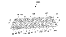
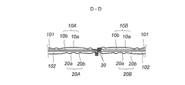
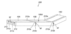
図6は本発明の第2の実施形態におけるエアーマットレス100Aの構成を示しており、図7はエアーマットレス100Aの連結部の断面(図6のD−D線断面)を示している。
FIG. 6 shows a configuration of an
図6及び図7に示すように、本実施形態におけるエアーマットレス100Aは、第1のエアーマット部材10A、10B及び10Cと、第2のエアーマット部材20A、20B及び20Cと、連結手段30とを備えている。第1のエアーマット部材10A、10B及び10Cと、第2のエアーマット部材20A、20B及び20Cは、エアーマットレス100Aの長さ方向(本実施形態において、以下単に長さ方向という)に相当する両サイド及びエアーマットレス100Aの幅方向(本実施形態において、以下単に幅方向という)に相当する辺の少なくとも一方側に連結用帯Sを有している。このエアーマットレス100Aは、第1のエアーマット部材10Aと第2のエアーマット部材20Aとが積層され両サイドが連結手段30で連結された積層体Aと、第1のエアーマット部材10Bと第2のエアーマット部材20Bの組合せ及び第1のエアーマット部材10Cと第2のエアーマット部材20Cの組合せがそれぞれ積層体A同様に積層連結された積層体Bと積層体Cが、長さ方向に配置され、隣接した積層体どうしを連結手段30により連結して構成されている。この3つの積層体はそれぞれ上述した第1の実施形態のエアーマットレス100と同様な構成を有しているため、その詳細説明は省略する。
As shown in FIGS. 6 and 7, the
また、エアーマットレス100Aにおいて、長さ方向に配置された3つの積層体にそれぞれ給排気口23が設けられている。具体的には、例えば、第2のエアーマット部材20A、20B及び20Cにおいて、第2の中間シート20bに、給排気口23が設けられている。また、第1のエアーマット部材10Aと第2のエアーマット部材20Aとの間、第1のエアーマット部材10Bと第2のエアーマット部材20Bとの間、及び第1のエアーマット部材10Cと第2のエアーマット部材20Cとの間に充填された空気が互いに流通可能な少なくとも1つの連通部40が設けられている。
Further, in the
図8はエアーマットレス100Aにおいて、給排気ポンプPを用いて空気の充填状態を示している。図8に示すように、エアーマットレス100Aに空気を充填する際に、長さ方向に配置された3つの部分のそれぞれ給排気口23から空気を充填すると、空気がそれぞれの連通部40を介して、第1のエアーマット部材10A、10B及び10Cと、第2のエアーマット部材20A、20B及び20Cとに充填される。
FIG. 8 shows a state of air filling using the air supply / exhaust pump P in the
本実施形態に係るエアーマットレス100Aは、上述した第1の実施形態のエアーマットレス100と同様な効果を得ることができる。また、長さ方向に配置された3つのエアーマット部材がお互いに隣接する連結用帯Sどうしを連結手段30により連結して構成されているため、背上げ、膝上げ等を行う際にエアーマットレス100Aの変形が容易になる。
The
上述したエアーマットレス100Aにおいて、長さ方向に配置された3つの積層体の連結は、第1のエアーマット部材10A及び10Bの連結用帯Sと、第2のエアーマット部材20A及び20Bの連結用帯Sとを一緒に連結されており(図7参照)、第1のエアーマット部材10B及び10Cの連結用帯Sと、第2のエアーマット部材20B及び20Cの連結用帯Sとを一緒に連結されている構成としたが、本発明はこれに限定されるものではない。例えば、図9に示す構成にしても良い。
In the
図9はエアーマットレス100Aにおいて、連結部の他の構成例を示している。図9に示すように、第1のエアーマット部材10A、10B及び10Cがそれぞれ隣接する連結用帯Sどうしを紐部材で縫合することで互いに連結され、第2のエアーマット部材20A、20B及び20Cが互いに連結されている。即ち、エアーマットレス100Aにおいて、長さ方向に配置された3つの積層体の連結は、第1のエアーマット部材10Aと10Bとを連結し、10Bと10Cとを連結する。また、第2のエアーマット部材20Aと20Bとを連結し、20Bと20Cとを連結する。そして、第1のエアーマット部材10A、10B及び10Cと、第2のエアーマット部材20A、20B及び20Cとの外周部を連結手段30で連結するように構成されている。これにより、第1のエアーマット部材10A、10B及び10C間の連結部は、ほぼ水平方向に位置することができ、連結部全体が硬くならず、使用者の寝心地がさらによくなる。
FIG. 9 shows another configuration example of the connecting portion in the
図10は本発明の第3の実施形態におけるエアーマットレス装置200の構成を示しており、図11はエアーマットレス装置200の断面(図10のE−E線断面)を示している。
FIG. 10 shows a configuration of an
図10及び図11に示すように、本実施形態におけるエアーマットレス装置200は、例えば、エアーマットレス100Aと、エアーマットレス100Aを支持する基台210とを備えている。なお、エアーマットレス100Aの代わりにエアーマットレス100を用いても良い。
As shown in FIGS. 10 and 11, the
基台210は、エアーマットレス100Aの下に設置された弾力性を有する敷き部材211と、エアーマットレス100Aの幅方向の両端側に配置された断面が略矩形の1対の端座部材212とから構成されている。なお、1対の端座部材212の断面形状は、これに限定されるものではない。
The base 210 includes a
敷き部材211は、硬さの異なる2層のクッション材、例えば、硬さの異なる2層のポリウレタン等の発泡材211a及び211bから、下層から硬度が大きい順に積層されて構成されている。各層の発泡材の硬さの好ましい例として、JIS K6401「耐荷重用軟質ポリウレタンフォーム」に準拠して測定した硬度として、下層のポリウレタン等の発泡材211aの硬度は150〜220Nが好ましく、上層のポリウレタン等の発泡材211bの硬度は60〜130Nであることが好ましい。なお、敷き部材211は、1層又は3層以上のポリウレタン等の発泡材から構成されても良い。
The laying
1対の端座部材212は、弾力性を有する材料、例えば所定の硬さを有するポリウレタン材から構成され、敷き部材211の外側に配置されている。この1対の端座部材212の硬度は、JIS K6401「耐荷重用軟質ポリウレタンフォーム」に準拠して測定した硬度として、例えば、150〜220Nであることが好ましい。これにより、使用者が座る時又は介助者が作業する時の沈みが少なく、型くずれを防止することができ、安定性を向上し、介助作業をしやすくなる。また、1対の端座部材212のエアーマットレス100Aの連結部に対応する位置に上面から幅方向に所定深さの切り込み212aが設けられている。さらに、1対の端座部材212には、エアーマットレス100Aを固定するための固定用紐Wを挿通可能な貫通穴212bが複数設けられている。
The pair of
また、空気を充填したエアーマットレス100Aは、使用者が使用する際には、その高さが1対の端座部材212とほぼ同じ高さになり、さらに、その幅方向の両端が1対の端座部材212に当接するように構成されている。この場合、1対の端座部材212は、エアーマットレス100Aの幅方向の変形を規制することができる。これにより、エアーマットレス100Aが安定して保持されると共に底付きの発生も抑制する。また、エアーマットレス100Aと基台210との間に段差及び隙間が生じないため、使用者の体も確実にエアーマットレス上に保持され、安全に使用することができる。なお、使用者が寝返りして端座部材212に当接したときに、端座部材212の硬さによって寝心地が低下する場合には、上記の端座部材212の効果を損なわない範囲において、空気を充填したエアーマットレス100Aの使用時の高さよりも端座部材212の高さを低く設定してもよい。
In addition, when the user uses the
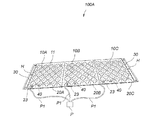
図12は、エアーマットレス装置200の使用状態の一例を示しており、同図において、エアーマットレス装置200における背上げの状態を示している。図12に示すように、エアーマットレス100Aが長さ方向に配置された3つの積層体を連結して構成されているため、背上げの際にエアーマットレス100Aの変形が容易になり、また、1対の端座部材212のエアーマットレス100Aの連結部に対応する位置に上面から幅方向に所定深さの切り込み212aが設けられているため、エアーマットレス装置200における背上げが容易にできる。
FIG. 12 shows an example of the usage state of the
以上説明したように、本実施形態によれば、エアーマットレス装置200は、エアーマットレス100Aと、基台210とを備え、基台210は、敷き部材211と、1対の端座部材212とから構成されていることで、エアーマットレス安定して保持されることができる。また、敷き部材211は、硬さの異なる2層のポリウレタン等の発泡材211a及び211bから、下層から硬度の大きい順に積層されて構成されていることで、柔軟性を確保できると共に、安定性も確保できる。また、万一エアーマットレスから空気漏れが発生して、基台が使用者を安全に受け止めたときに、敷き部材の柔軟性によって体圧分散性を維持しながら使用者を支持することができる。また、1対の端座部材212は、弾力性を有するものであり、かつエアーマットレス100Aの連結部に対応する位置に上面から幅方向に所定深さの切り込み212aが設けられていることで、背上げ、膝上げ等の際にエアーマットレス装置の変形が容易になる。さらに、1対の端座部材212には、エアーマットレス100Aを固定するための紐Wを挿通可能な貫通穴212bが複数設けられていることで、エアーマットレス100Aの位置ずれを防止することができる。
As described above, according to the present embodiment, the
なお、上述した本発明における実施形態のエアーマットレス100及び100Aにおいて、給排気口23は、第2の中間シート20bに設けられている例を説明したが、本発明はこれに限定されるものではない。給排気口23は第1の中間シート10bに設けても良い。また、本実施形態における給排気口23のかわりに、給気口と排気口とをそれぞれ設け、給排気管P1のかわりに、給気管と排気管とをそれぞれ接続させても良い。
In the
また、上述した本発明における実施形態のエアーマットレス100及び100Aにおいて、連結手段30は、第1のエアーマット部材10及び第2のエアーマット部材20の外周部を縫着する紐部材と縫合孔とから構成されている例を説明したが、本発明はこれに限定されるものではない。例えば、縫製糸による縫着、クリップによる挟着等の手段であっても良い。
In the
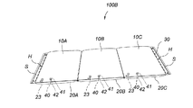
また、上述した本発明における実施形態のエアーマットレス100及び100Aにおいて、接着部が線状の接着筋11及び21の配置パターンとしたが、接着部の形状や配置パターンは、これに限定されるものではない。また、接着部がない構成としても良い。例えば、図13に示すように、エアーマットレス100Bは、第1のエアーマット部材10A、10B及び10Cと、第2のエアーマット部材20A、20B及び20Cとは、接着部がない構成となっている。なお、エアーマットレス100Bにおいて、接着部がない以外、上述した第2の実施形態におけるエアーマットレス100Aと同様な構成を有している。
Moreover, in the
また、上述した本発明における実施形態のエアーマットレス100及び100Aにおいて、第1のエアーマット部材10と、第2のエアーマット部材20とを積層して構成された例を説明したが、本発明はこれに限定されるものではない。第1のエアーマット部材10と第2のエアーマット部材20とが、形状や接着パターンが同じでもよいし、異なっていても良い。また、3以上のエアーマット部材を積層して構成されても良い。さらに、第1のエアーマット部材10と、第2のエアーマット部材20とを連通させる連通部40を設けずに、第1のエアーマット部材10と第2のエアーマット部材20とを独立に空気充填しても良い。
In the above-described
また、上述した本発明における実施形態のエアーマットレス100Aにおいて、各積層体を一列に配置して連結した構成を例示したが、用途に応じてL字やT字等の配置としてもよいし、複数列に配置してもよい。
Moreover, in the
さらに、上述した本発明における実施形態のエアーマットレス装置200において、エアーマットレス100Aの幅方向の両端側に1対の端座部材212が配置された例を説明したが、本発明はこれに限定されるものではない。エアーマットレス100Aの長さ方向の両端側にも端座部材を設けても良い。
Furthermore, in the
本発明のエアーマットレス及びエアーマットレス装置は、気体を充填して封止した状態でそのまま使用することもできるし、給排気口を通じて気体の供給、排気を公知の方法で制御して使用することもできる。また、本発明の第2の実施形態のように長さ方向に複数のエアーマット部材が配置されて、各エアーマット部材を個別に給排気制御してもよく、例えば圧切替型のエアーマットレスのような制御を適用しても良い。 The air mattress and the air mattress device of the present invention can be used as they are in a state of being filled with gas and sealed, or can be used by controlling supply and exhaust of gas through a supply / exhaust port by a known method. it can. Further, as in the second embodiment of the present invention, a plurality of air mat members may be arranged in the length direction, and the air mat members may be individually supplied and exhausted. For example, a pressure switching type air mattress Such control may be applied.
以上述べた実施形態は全て本発明を例示的に示すものであって限定的に示すものではなく、本発明は他の種々の変形態様及び変更態様で実施することができる。従って本発明の範囲は特許請求の範囲及びその均等範囲によってのみ規定されるものである。 All the embodiments described above are illustrative of the present invention and are not intended to be limiting, and the present invention can be implemented in other various modifications and changes. Therefore, the scope of the present invention is defined only by the claims and their equivalents.
10、10A、10B、10C 第1のエアーマット部材
10a 第1の表層シート
10b 第1の中間シート
11、21 接着筋
20、20A、20B、20C 第2のエアーマット部材
20a 第2の表層シート
20b 第2の中間シート
23 給排気口
30 連結手段
40 連通部
41、42 接続アダプタ
100、100A、100B エアーマットレス
101、102 空気室
200 エアーマットレス装置
210 基台
211 敷き部材
211a、211b 発泡材
212 端座部
212a 切り込み
212b 貫通穴
H 固定用貫通孔
P 給排気ポンプ
P1 給排気管
S 連結用帯
W 固定用紐
10, 10A, 10B, 10C First
Claims (12)
第2の表層シートと第2の中間シートとを積層し、外周部を封止して構成された空気を充填可能な第2のエアーマット部材と、
前記第1のエアーマット部材と前記第2のエアーマット部材とを積層した状態で各エアーマット部材の周端部に備えられた連結用帯のうち、少なくとも両サイドの連結用帯を互いに連結する連結手段とを備え、
前記連結手段は、前記第1のエアーマット部材及び前記第2のエアーマット部材の外周部を縫着する紐部材から構成されていることを特徴とするエアーマットレス。 A first air mat member that can be filled with air formed by laminating a first surface layer sheet and a first intermediate sheet and sealing an outer periphery;
A second air mat member that can be filled with air that is formed by laminating the second surface layer sheet and the second intermediate sheet and sealing the outer periphery;
In the state where the first air mat member and the second air mat member are laminated, at least the connecting bands on both sides are connected to each other among the connecting bands provided at the peripheral end of each air mat member. Connecting means,
The air mattress is characterized in that the connecting means is composed of a string member for sewing the outer periphery of the first air mat member and the second air mat member.
隣接する前記積層体は、隣接する前記第1のエアーマット部材の連結用帯どうしの連結、及び隣接する前記第2のエアーマット部材の連結用帯どうしの連結によって互いに連結されていることを特徴とする請求項1に記載のエアーマットレス。 A plurality of laminated bodies configured in a state where the first air mat member and the second air mat member are laminated by the connecting means are configured in a horizontal direction;
The adjacent laminates are connected to each other by connecting the connecting bands of the adjacent first air mat members and connecting the connecting bands of the adjacent second air mat members. The air mattress according to claim 1.
隣接する前記積層体は、前記第1のエアーマット部材と前記第2のエアーマット部材との連結用帯が重ねて連結されていることを特徴とする請求項1に記載のエアーマットレス。 A plurality of laminated bodies configured in a state where the first air mat member and the second air mat member are laminated by the connecting means are configured in a horizontal direction;
2. The air mattress according to claim 1, wherein the adjacent stacked bodies are connected by overlapping bands for connecting the first air mat member and the second air mat member.
前記第1のエアーマット部材の前記線状の接着筋は、前記第2のエアーマット部材の前記線状の接着筋と、平面視交差する位置に配置されていることを特徴とする請求項8に記載のエアーマットレス。 The adhesive part of the first air mat member is a linear adhesive line, the adhesive part of the second air mat member is a linear adhesive line,
9. The linear adhesive bar of the first air mat member is disposed at a position intersecting with the linear adhesive bar of the second air mat member in plan view. The air mattress described in 1.
前記エアーマットレスを支持する基台とを備え、
前記基台は、前記エアーマットレスの下に設置された弾力性を有する敷き部材と、前記エアーマットレスの幅方向の両端側に配置された1対の端座部材とから構成されていることを特徴とするエアーマットレス装置。 The air mattress according to any one of claims 1 to 9,
A base that supports the air mattress;
The base is composed of a resilient laying member installed under the air mattress and a pair of end seat members disposed at both ends in the width direction of the air mattress. Air mattress device.
Priority Applications (1)
| Application Number | Priority Date | Filing Date | Title |
|---|---|---|---|
| JP2016084310A JP6670667B2 (en) | 2016-04-20 | 2016-04-20 | Air mattress and air mattress device |
Applications Claiming Priority (1)
| Application Number | Priority Date | Filing Date | Title |
|---|---|---|---|
| JP2016084310A JP6670667B2 (en) | 2016-04-20 | 2016-04-20 | Air mattress and air mattress device |
Publications (2)
| Publication Number | Publication Date |
|---|---|
| JP2017192541A true JP2017192541A (en) | 2017-10-26 |
| JP6670667B2 JP6670667B2 (en) | 2020-03-25 |
Family
ID=60155107
Family Applications (1)
| Application Number | Title | Priority Date | Filing Date |
|---|---|---|---|
| JP2016084310A Expired - Fee Related JP6670667B2 (en) | 2016-04-20 | 2016-04-20 | Air mattress and air mattress device |
Country Status (1)
| Country | Link |
|---|---|
| JP (1) | JP6670667B2 (en) |
Cited By (3)
| Publication number | Priority date | Publication date | Assignee | Title |
|---|---|---|---|---|
| JP2020110649A (en) * | 2020-04-02 | 2020-07-27 | パラマウントベッド株式会社 | Air mattress |
| CN112089547A (en) * | 2020-10-19 | 2020-12-18 | 张庆娟 | ICU nursing patient stands up supplementary strutting arrangement |
| CN112841994A (en) * | 2020-03-31 | 2021-05-28 | 株式会社安适 | Portable mattress |
Families Citing this family (1)
| Publication number | Priority date | Publication date | Assignee | Title |
|---|---|---|---|---|
| KR102602972B1 (en) * | 2021-07-01 | 2023-11-16 | (주)파크론 | Mat for easy ejecting of internal air |
Citations (6)
| Publication number | Priority date | Publication date | Assignee | Title |
|---|---|---|---|---|
| US5044030A (en) * | 1990-06-06 | 1991-09-03 | Fabrico Manufacturing Corporation | Multiple layer fluid-containing cushion |
| JPH10215983A (en) * | 1997-02-07 | 1998-08-18 | Reiichi Okada | Lower spread bedding provided with slide preventing means |
| US20120096648A1 (en) * | 2010-10-25 | 2012-04-26 | Cheng-Yang Chan | Air Tool With Modularized Air Pad |
| JP2014064692A (en) * | 2012-09-25 | 2014-04-17 | Hiroshima Univ | Mattress and control method of the same |
| JP2015223340A (en) * | 2014-05-28 | 2015-12-14 | 株式会社タイカ | Air mattress |
| JP2016005535A (en) * | 2014-05-28 | 2016-01-14 | 株式会社タイカ | Mat filled with liquid |
-
2016
- 2016-04-20 JP JP2016084310A patent/JP6670667B2/en not_active Expired - Fee Related
Patent Citations (6)
| Publication number | Priority date | Publication date | Assignee | Title |
|---|---|---|---|---|
| US5044030A (en) * | 1990-06-06 | 1991-09-03 | Fabrico Manufacturing Corporation | Multiple layer fluid-containing cushion |
| JPH10215983A (en) * | 1997-02-07 | 1998-08-18 | Reiichi Okada | Lower spread bedding provided with slide preventing means |
| US20120096648A1 (en) * | 2010-10-25 | 2012-04-26 | Cheng-Yang Chan | Air Tool With Modularized Air Pad |
| JP2014064692A (en) * | 2012-09-25 | 2014-04-17 | Hiroshima Univ | Mattress and control method of the same |
| JP2015223340A (en) * | 2014-05-28 | 2015-12-14 | 株式会社タイカ | Air mattress |
| JP2016005535A (en) * | 2014-05-28 | 2016-01-14 | 株式会社タイカ | Mat filled with liquid |
Cited By (5)
| Publication number | Priority date | Publication date | Assignee | Title |
|---|---|---|---|---|
| CN112841994A (en) * | 2020-03-31 | 2021-05-28 | 株式会社安适 | Portable mattress |
| CN112841994B (en) * | 2020-03-31 | 2023-03-28 | 株式会社安适 | Portable mattress |
| JP2020110649A (en) * | 2020-04-02 | 2020-07-27 | パラマウントベッド株式会社 | Air mattress |
| JP7042863B2 (en) | 2020-04-02 | 2022-03-28 | パラマウントベッド株式会社 | Air mattress |
| CN112089547A (en) * | 2020-10-19 | 2020-12-18 | 张庆娟 | ICU nursing patient stands up supplementary strutting arrangement |
Also Published As
| Publication number | Publication date |
|---|---|
| JP6670667B2 (en) | 2020-03-25 |
Similar Documents
| Publication | Publication Date | Title |
|---|---|---|
| US8127386B2 (en) | Air mattress | |
| US8635726B2 (en) | Cushion bladder with middle layer having gaps and various positioned interior welds | |
| CN104244896B (en) | Improve the mattress of nursing/medical treatment fitness | |
| JP2017192541A (en) | Air mattress and air mattress device | |
| JP6284499B2 (en) | Fluid-filled rug | |
| KR101989441B1 (en) | Multi-layered Memory Foam Mattress | |
| US8978185B1 (en) | Mattress pad or mattress topper with an oval support portion | |
| JP2009279086A (en) | Bed mattress | |
| JP6400867B1 (en) | Air mattress | |
| WO2020050317A1 (en) | Air mattress and air cell | |
| WO2020071525A1 (en) | Air cell part, air cell unit, and air mattress | |
| AU2021100726A4 (en) | Upholstered furniture core and upholstered furniture item | |
| JP5871377B2 (en) | Mattress cushion | |
| JP6832771B2 (en) | Air mat device | |
| JPWO2017183218A1 (en) | Multilayer cushion and mattress with the same | |
| CN204599944U (en) | Air mattress | |
| JP2009178284A (en) | Cushion body and cushion device | |
| CN203943840U (en) | a foam pad | |
| JPH09224983A (en) | Air mat device | |
| KR20160004011U (en) | Bedsore prevention mat | |
| JP3167964U (en) | Wheelchair cushion | |
| KR102691222B1 (en) | Sleeping mattress assembly including hard and thin cushion mat, bed including the same and cushion mat therefor | |
| CN211356102U (en) | Scoliosis correcting cushion | |
| JP3124520U (en) | Body support | |
| JP2010046306A (en) | Cushion body |
Legal Events
| Date | Code | Title | Description |
|---|---|---|---|
| A621 | Written request for application examination |
Free format text: JAPANESE INTERMEDIATE CODE: A621 Effective date: 20190328 |
|
| A977 | Report on retrieval |
Free format text: JAPANESE INTERMEDIATE CODE: A971007 Effective date: 20200207 |
|
| TRDD | Decision of grant or rejection written | ||
| A01 | Written decision to grant a patent or to grant a registration (utility model) |
Free format text: JAPANESE INTERMEDIATE CODE: A01 Effective date: 20200225 |
|
| A61 | First payment of annual fees (during grant procedure) |
Free format text: JAPANESE INTERMEDIATE CODE: A61 Effective date: 20200302 |
|
| R150 | Certificate of patent or registration of utility model |
Ref document number: 6670667 Country of ref document: JP Free format text: JAPANESE INTERMEDIATE CODE: R150 |
|
| LAPS | Cancellation because of no payment of annual fees |