JP2017191790A - connector - Google Patents

connector Download PDF

Info

Publication number
JP2017191790A
JP2017191790A JP2017144985A JP2017144985A JP2017191790A JP 2017191790 A JP2017191790 A JP 2017191790A JP 2017144985 A JP2017144985 A JP 2017144985A JP 2017144985 A JP2017144985 A JP 2017144985A JP 2017191790 A JP2017191790 A JP 2017191790A
Authority
JP
Japan
Prior art keywords
contact
slider
fpc
pressing portion
pressing
Prior art date
Legal status (The legal status is an assumption and is not a legal conclusion. Google has not performed a legal analysis and makes no representation as to the accuracy of the status listed.)
Granted
Application number
JP2017144985A
Other languages
Japanese (ja)
Other versions
JP6212671B1 (en
JP6212671B6 (en
Inventor
鈴木 雅幸
Masayuki Suzuki
雅幸 鈴木
Current Assignee (The listed assignees may be inaccurate. Google has not performed a legal analysis and makes no representation or warranty as to the accuracy of the list.)
DDK Ltd
Original Assignee
DDK Ltd
Priority date (The priority date is an assumption and is not a legal conclusion. Google has not performed a legal analysis and makes no representation as to the accuracy of the date listed.)
Filing date
Publication date
Application filed by DDK Ltd filed Critical DDK Ltd
Priority to JP2017144985A priority Critical patent/JP6212671B6/en
Priority claimed from JP2017144985A external-priority patent/JP6212671B6/en
Publication of JP6212671B1 publication Critical patent/JP6212671B1/en
Publication of JP2017191790A publication Critical patent/JP2017191790A/en
Application granted granted Critical
Publication of JP6212671B6 publication Critical patent/JP6212671B6/en
Anticipated expiration legal-status Critical
Expired - Lifetime legal-status Critical Current

Links

Images

Landscapes

  • Coupling Device And Connection With Printed Circuit (AREA)

Abstract

PROBLEM TO BE SOLVED: To provide a connector having good workability, enabling an FPC 40 or FFC to securely press a contacting part 22 of a contact 14 with a slider 16 without damaging strength, specifications, etc. of each part, and enabling a narrow pitch and a low profile.SOLUTION: The connector includes an elastic part 34 and a fulcrum part 32 that are disposed between a contacting part 22 and a connection part 24 of the contact 14. The contacting part 22, the elastic part 34, the fulcrum part 32 and the connection part 24 are arranged in a substantial crank shape. The connector further includes a pressure reception part 20 extending from the elastic part 34 at a position opposite to the connection part 24, and also a pressing part 36 communicating with a slider 16 in the longitudinal direction. The pressing part 36 rotatably mounts the slider 16 on a housing 12 between the connection part 22 of the contact 14 and the pressure reception part 20, thereby achieving the low profile.SELECTED DRAWING: Figure 2

Description

本発明は、携帯電話やノートパソコンやデジタルカメラ等に使用されるコネクタに関するもので、特にフレキシブルプリント基板(以下「FPC」という)やフレキシブルフラットケーブル(以下「FFC」という)にコンタクトを押し付ける機構に関するものである。   The present invention relates to a connector used in a mobile phone, a notebook computer, a digital camera, and the like, and more particularly to a mechanism for pressing a contact against a flexible printed circuit board (hereinafter referred to as “FPC”) or a flexible flat cable (hereinafter referred to as “FFC”). Is.

携帯電話やCCDカメラ等に使用されるコネクタは、狭ピッチで極薄(所謂軽薄短小)であり、主にハウジングとコンタクトとスライダーとから構成され、ハウジングとスライダーとでFPC又はFFCを挟持する構造である。ハウジングとスライダーとでFPC又はFFCを保持する方法には、色々考えられるが、中でもハウジングにFPC又はFFCを挿入した後にスライダーを挿入しFPC又はFFCをコンタクトに押しつける構造のものが多い。   A connector used for a cellular phone, a CCD camera, etc. is a narrow pitch and extremely thin (so-called light thin short), and is mainly composed of a housing, a contact, and a slider, and the housing and the slider sandwich the FPC or FFC. It is. There are various methods for holding the FPC or FFC between the housing and the slider. However, there are many methods in which the slider is inserted after the FPC or FFC is inserted into the housing and the FPC or FFC is pressed against the contact.

ハウジングには、コンタクトが挿入される所要数の挿入孔が設けられるとともにFPC又はFFCが挿入される嵌合口が設けられている。   The housing is provided with a required number of insertion holes into which contacts are inserted and a fitting port into which an FPC or FFC is inserted.

コンタクト64は図8のように略コ字形状をしており、主にFPC40又はFFCと接触する接触部22と基板等に接続する接続部24とハウジング62に固定される固定部42とから構成されている。このコンタクト64は、圧入等によってハウジング62に固定されている。   The contact 64 is substantially U-shaped as shown in FIG. 8, and is mainly composed of a contact portion 22 that contacts the FPC 40 or FFC, a connection portion 24 connected to a substrate or the like, and a fixed portion 42 fixed to the housing 62. Has been. The contact 64 is fixed to the housing 62 by press fitting or the like.

例えば、スライダー66は、図8のように略楔形状をしており、所要数のコンタクト64が配置されたハウジング62に、FPC40又はFFCを挿入した後に、前記スライダー66を挿入する。このようなスライダー66は、主にハウジング62に装着される装着部74とFPC40又はFFCをコンタクト64の接触部22に押圧する押圧部68とを備えている。FPC40又はFFCが挿入される以前は、スライダー66はハウジング62に仮装着された状態になっており、FPC40又はFFCが挿入された後にスライダー66を挿入すると、図8(B)のようにFPC40又はFFCと平行に前記スライダー66の押圧部68が挿入され、コンタクト64の接触部22にFPC40又はFFCが押圧されるようになる。   For example, the slider 66 has a substantially wedge shape as shown in FIG. 8, and after inserting the FPC 40 or FFC into the housing 62 in which the required number of contacts 64 are arranged, the slider 66 is inserted. The slider 66 includes a mounting portion 74 that is mainly mounted on the housing 62 and a pressing portion 68 that presses the FPC 40 or FFC against the contact portion 22 of the contact 64. Before the FPC 40 or FFC is inserted, the slider 66 is temporarily attached to the housing 62. When the slider 66 is inserted after the FPC 40 or FFC is inserted, the FPC 40 or FPC is inserted as shown in FIG. The pressing portion 68 of the slider 66 is inserted in parallel with the FFC, and the FPC 40 or FFC is pressed against the contact portion 22 of the contact 64.

近年、この種のコネクタ60には、より低背位化の要求が強くなってきているが、上述した構造のコネクタ60では、図8(B)のように6層(ハウジング62の厚み方向両側の壁・コンタクト64の接触部22と受け部70の厚さ・スライダー66の押圧部68の厚さ・FPC40又はFFCの厚さ)構造になっている。低背位化を考えると、コンタクト64の受け部70を省略し、5層(ハウジング62の厚み方向両側の壁・コンタクト64の接触部22の厚さ・スライダー66の押圧部68の厚さ・FPC40又はFFCの厚さ)構造にすることはできるが、各部位の強度や仕様等からこれ以上低背位化が出来ないといった解決すべき課題があった。   In recent years, this type of connector 60 has been increasingly required to have a lower profile, but the connector 60 having the above-described structure has six layers (both sides in the thickness direction of the housing 62) as shown in FIG. The thickness of the contact portion 22 of the contact 64 and the receiving portion 70, the thickness of the pressing portion 68 of the slider 66, and the thickness of the FPC 40 or FFC). Considering the low profile, the receiving part 70 of the contact 64 is omitted, and five layers (the walls on both sides in the thickness direction of the housing 62, the thickness of the contact part 22 of the contact 64, the thickness of the pressing part 68 of the slider 66, The thickness of the FPC 40 or the FFC) can be made, but there is a problem to be solved such that the height cannot be lowered any more due to the strength and specifications of each part.

また、上述のような構造のコネクタ60では、ハウジング62の嵌合口18側のみで、FPC40又はFFCの挿入とコンタクト64の接触部22をFPC40又はFFCに押しつける動作を行っているので、コネクタが小型化すればするほど作業性が悪いと言った問題点もある。   Further, in the connector 60 having the structure as described above, the FPC 40 or FFC is inserted and the contact portion 22 of the contact 64 is pressed against the FPC 40 or FFC only on the fitting port 18 side of the housing 62, so the connector is small. There is also the problem that workability becomes worse the more it becomes.

さらにまた、コネクタ60のピッチの狭小化が要求された場合、従来の構造のようにコンタクト64を一方向から挿入したのでは、コネクタの狭小化にも限界があった。   Furthermore, when it is required to narrow the pitch of the connector 60, if the contacts 64 are inserted from one direction as in the conventional structure, there is a limit to narrowing the connector.

本発明は、このような従来の問題点に鑑みてなされたもので、各部位の強度や仕様等を損なうことなく、スライダー16でFPC40又はFFCを確実にコンタクト14の接触部22に押圧することができ、作業性がよく、ピッチの狭小化や低背位化が可能なコネクタを提供せんとするものである。   The present invention has been made in view of such conventional problems, and the FPC 40 or the FFC is reliably pressed against the contact portion 22 of the contact 14 by the slider 16 without impairing the strength and specifications of each part. Therefore, it is intended to provide a connector that can be manufactured, has good workability, and can reduce the pitch and reduce the height.

上記目的の低背位化は、FPC40又はFFCと着脱自在に嵌合するコネクタ10であって、該FPC40又は前記FFCと接触する接触部22を有する所要数のコンタクト14と、このコンタクト14が保持・固定されるとともに前記FPC40又は前記FFCが挿入される嵌合口18を有するハウジング12と、前記FPC40又は前記FFCを前記コンタクト14に押圧するスライダー16とを備えるコネクタ10において、前記コンタクト14の接触部22と接続部24との間に弾性部34と支点部32とを設けるとともに前記接触部22と前記弾性部34と前記支点部32と前記接続部24とを略クランク形状に配置し、かつ、前記接続部24と対向する位置に前記弾性部34から延設された押受部20を設け、前記スライダー16に長手方向に連設した押圧部36を設け、該押圧部36が前記コンタクト14の接続部22と押受部20との間で回動自在に前記スライダー16を前記ハウジング12に装着することにより達成できる。   The low profile for the above purpose is a connector 10 that is detachably fitted to the FPC 40 or FFC, and has a required number of contacts 14 having contact portions 22 that contact the FPC 40 or the FFC, and the contacts 14 hold The contact portion of the contact 14 in the connector 10 including the housing 12 having the fitting port 18 into which the FPC 40 or the FFC is inserted and the slider 16 that presses the FPC 40 or the FFC against the contact 14. An elastic part 34 and a fulcrum part 32 between the contact part 22 and the connection part 24, the contact part 22, the elastic part 34, the fulcrum part 32 and the connection part 24 are arranged in a substantially crank shape, and A pressing portion 20 extending from the elastic portion 34 is provided at a position facing the connecting portion 24, and the slider 1 By providing a pressing portion 36 continuously provided in the longitudinal direction, the pressing portion 36 is mounted on the housing 12 so as to be rotatable between the connection portion 22 of the contact 14 and the pressing portion 20. Can be achieved.

上記目的の低背位化とピッチの狭小化は、FPC40又はFFCと着脱自在に嵌合するコネクタ101であって、該FPC40又は前記FFCと接触する接触部22を有する所要数のコンタクト14、142と、このコンタクト14、142が保持・固定されるとともに前記FPC又は前記FFCが挿入される嵌合口18を有するハウジング121と、前記FPC40又は前記FFCを前記コンタクト14、142に押圧するスライダー161とを備えるコネクタ101において、2種類のコンタクト14、142を千鳥に配置し、一方のコンタクト14には、接触部22と接続部24との間に弾性部34と支点部32とを設けるとともに前記接触部22と前記弾性部34と前記支点部32と前記接続部24とを略クランク形状に配置し、かつ、前記接続部24と対向する位置に前記弾性部34から延設された押受部20を設け、もう一方のコンタクト142には、接触部22と接続部24との間に弾性部34と支点部32とを設けるとともに前記接触部22と前記弾性部34と前記支点部32と前記接続部24とを略コ字状に配置し、かつ、前記弾性部34から接触部22と反対方向に延設された押受部20を設け、前記スライダー161に長手方向に連設した押圧部36を設け、該押圧部36が一方のコンタクト14の接続部24と押受部20との間及びもう一方のコンタクト142の押受部20と前記ハウジング121との間で回動自在に前記スライダー161を前記ハウジング121に装着することにより達成できる。   The above-mentioned purpose of lowering the back and narrowing the pitch is a connector 101 that is detachably fitted to the FPC 40 or FFC, and has a required number of contacts 14 and 142 having contact portions 22 that contact the FPC 40 or the FFC. And a housing 121 having a fitting port 18 into which the contacts 14 and 142 are held and fixed and the FPC or the FFC is inserted, and a slider 161 that presses the FPC 40 or the FFC against the contacts 14 and 142. In the connector 101 provided, two types of contacts 14 and 142 are arranged in a staggered manner, and one contact 14 is provided with an elastic portion 34 and a fulcrum portion 32 between the contact portion 22 and the connection portion 24 and the contact portion. 22, the elastic portion 34, the fulcrum portion 32, and the connection portion 24 are arranged in a substantially crank shape. The pressing portion 20 extending from the elastic portion 34 is provided at a position facing the connection portion 24, and the elastic portion 34 and the fulcrum between the contact portion 22 and the connection portion 24 are provided on the other contact 142. The contact portion 22, the elastic portion 34, the fulcrum portion 32, and the connection portion 24 are arranged in a substantially U shape and extend from the elastic portion 34 in the opposite direction to the contact portion 22. A pressing portion 20 is provided, and a pressing portion 36 provided in the longitudinal direction is provided on the slider 161, and the pressing portion 36 is between the connection portion 24 of one contact 14 and the pressing portion 20 and the other. This can be achieved by mounting the slider 161 to the housing 121 so as to be rotatable between the holding portion 20 of the contact 142 and the housing 121.

一方若しくはもう一方の前記コンタクト14、142の押受部20の先端に突出部26を設け、前記スライダー161の押圧部36が一方の前記コンタクト14の接続部24方向へ移動しないようにすることが望ましい。このように突出部26を設けることで、スライダー161の押圧部36をコンタクト14の押受部20と接続部24との間で回動させるときスライダー161の回動に対する反発力が強い為に、スライダー161の中央部が図6(B)の矢印「ハ」方向に膨れてしまうことを防ぐことが出来る。   Protruding portion 26 is provided at the tip of pressing portion 20 of one or the other of contacts 14 and 142 so that pressing portion 36 of slider 161 does not move toward connecting portion 24 of one of contacts 14. desirable. By providing the protruding portion 26 in this manner, when the pressing portion 36 of the slider 161 is rotated between the pressing portion 20 of the contact 14 and the connecting portion 24, the repulsive force against the rotation of the slider 161 is strong. It is possible to prevent the center portion of the slider 161 from bulging in the direction of the arrow “C” in FIG.

また、前記スライダー16、161の押圧部36の形状を細長形状にすることが望ましい。例えば、楕円形にすると良い。このように細長形状にすることで、前記スライダー16、161を回動した際に、確実に前記コンタクト14、141、142の押受部20を上方に押し上げ、接触部22をFPC40又はFFCに容易に接触させることができる。   In addition, it is preferable that the shape of the pressing portion 36 of the sliders 16 and 161 is an elongated shape. For example, it may be oval. By adopting such an elongated shape, when the sliders 16 and 161 are rotated, the pressing portions 20 of the contacts 14, 141 and 142 are surely pushed upward, and the contact portions 22 can be easily moved to the FPC 40 or FFC. Can be contacted.

前記スライダー16、161には、所要数の前記コンタクト14、141、142の突出部26と係合する係止孔30を設け、該係止孔30を別個独立にした方がよい。このように前記係止孔30を別個独立にすることで、前記スライダー16、161を強固で、確実に回動することができる。   The sliders 16 and 161 are preferably provided with locking holes 30 that engage with the protrusions 26 of the required number of the contacts 14, 141, and 142, and the locking holes 30 are made independent. Thus, by making the said locking hole 30 independent independently, the said sliders 16 and 161 can be rotated firmly and reliably.

また、一方の前記コンタクト142の支点部32から延設した方向にも前記FPC40又はFFCと接触する接触部22を設ける。このように前記FPC40又はFFCの挿入方向に対して、直角方向両側に接触部22を設けることで、前記FPC40又はFFCを接触部22、22で挟持することになり、確実に前記FPC40又はFFCと接触できるようになる。   Further, a contact portion 22 that contacts the FPC 40 or FFC is also provided in a direction extending from the fulcrum portion 32 of the one contact 142. Thus, by providing the contact portions 22 on both sides in a direction perpendicular to the insertion direction of the FPC 40 or FFC, the FPC 40 or FFC is sandwiched between the contact portions 22 and 22, and the FPC 40 or FFC is securely connected to the FPC 40 or FFC. You can touch.

さらにまた、もう一方の前記コンタクト142の支点部32と接続部24との間にも前記FPC40又はFFCと接触する接触部22を設ける。このように前記FPC40又はFFCの挿入方向に対して、直角方向両側に接触部22を設けることで、前記FPC40又はFFCを接触部22、22で挟持することになり、確実に前記FPC40又はFFCと接触できるようになる。   Furthermore, a contact portion 22 that contacts the FPC 40 or FFC is provided between the fulcrum portion 32 and the connection portion 24 of the other contact 142. Thus, by providing the contact portions 22 on both sides in a direction perpendicular to the insertion direction of the FPC 40 or FFC, the FPC 40 or FFC is sandwiched between the contact portions 22 and 22, and the FPC 40 or FFC is securely connected to the FPC 40 or FFC. You can touch.

前記もう一方のコンタクト142の前記支点部32から接続部24と反対方向に延設された延設部44を設け、前記スライダー161の押圧部36が延設部44と押受部20との間で回動自在に前記スライダー161を前記ハウジング121に装着する。このように延設部44を設け、この延設部44と前記押受部20との間でスライダー161を回動させることで、回動させた際により確実にもう一方のコンタクト142の接触部22を前記FPC40又はFFCに押圧することができる。   An extension part 44 extending from the fulcrum part 32 of the other contact 142 in the direction opposite to the connection part 24 is provided, and the pressing part 36 of the slider 161 is located between the extension part 44 and the pressing part 20. The slider 161 is mounted on the housing 121 so as to be freely rotatable. By providing the extended portion 44 as described above and rotating the slider 161 between the extended portion 44 and the pressing portion 20, the contact portion of the other contact 142 is more reliably rotated. 22 can be pressed against the FPC 40 or FFC.

前記FPC40又はFFCが前記ハウジング12、121の嵌合口18内に挿入された後に、前記スライダー16、161の押圧部36が一方の前記コンタクト14の接続部24と押受部36及びもう一方の前記コンタクト142の押受部20と延設部44との間で回動すると、前記押受部20が押圧部36によって押し上げられることで両方の前記コンタクト14、142の支点部32を支点にし、両方の前記コンタクト14、142の弾性部34が前記接触部24側に傾くことによって、前記接触部22が前記FPC40又はFFC側に押圧される。 After the FPC 40 or FFC is inserted into the fitting port 18 of the housing 12, 121, the pressing portion 36 of the slider 16, 161 is connected to the connecting portion 24, the pressing portion 36 of the one contact 14, and the other of the above-described one. When rotating between the pressing portion 20 of the contact 142 and the extending portion 44, the pressing portion 20 is pushed up by the pressing portion 36, and the fulcrum portion 32 of both the contacts 14, 142 is used as a fulcrum. When the elastic part 34 of the contacts 14 and 142 is inclined toward the contact part 24 side, the contact part 22 is pressed toward the FPC 40 or FFC side.

(A) スライダーが開いた状態の嵌合口側からみた本発明のコネクタの斜視図である。(B) スライダーが開いた状態の接続部側からみた本発明のコネクタの斜視図である。(A) It is a perspective view of the connector of this invention seen from the fitting port side of the state which the slider opened. (B) It is the perspective view of the connector of this invention seen from the connection part side in the state where the slider opened. (A) スライダーが開いた状態のあるコンタクト部分で切断した本発明のコネクタの斜視図である。(B) FPCが挿入されスライダーが閉じた状態のあるコンタクト部分で切断した本発明のコネクタの斜視図である。(A) It is a perspective view of the connector of this invention cut | disconnected by the contact part with the state which the slider opened. (B) It is a perspective view of the connector of this invention cut | disconnected by the contact part with the state which inserted FPC and the slider closed. スライダーの斜視図である。It is a perspective view of a slider. (A) 2つの接触部を持ったコンタクトの斜視図である。(B) 1つの接触部を持った別のコンタクトの斜視図である。(A) It is a perspective view of a contact with two contact parts. (B) It is a perspective view of another contact which has one contact part. 別のコネクタの斜視図である。It is a perspective view of another connector. (A) スライダーが開いた状態のもう一方のコンタクト部分で切断した本発明の別のコネクタの斜視図である。(B) FPCが挿入されスライダーが閉じた状態のもう一方のコンタクト部分で切断した本発明の別のコネクタの斜視図である。(A) It is a perspective view of another connector of this invention cut | disconnected by the other contact part of the state in which the slider was open. (B) It is a perspective view of another connector of this invention cut | disconnected by the other contact part of the state which FPC was inserted and the slider closed. スライダーが挿入される前の嵌合口側からみた従来のコネクタの斜視図である。It is a perspective view of the conventional connector seen from the fitting port side before a slider is inserted. (A) スライダーが挿入される前のあるコンタクト部分で切断した従来のコネクタの斜視図である。(B) FPCが挿入されスライダーが挿入された状態のあるコンタクト部分で切断した従来のコネクタの斜視図である。(A) It is a perspective view of the conventional connector cut | disconnected by a certain contact part before a slider is inserted. (B) It is a perspective view of the conventional connector cut | disconnected by the contact part with the state in which FPC was inserted and the slider was inserted.

図1から図4に基づいて、本発明のコネクタの一実施例について説明する。
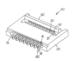
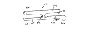
図1(A)はスライダーが開いた状態の嵌合口側からみた本発明のコネクタの斜視図であり、(B)はスライダーが開いた状態の接続部側からみた本発明のコネクタの斜視図である。図2(A)はスライダーが開いた状態のあるコンタクト部分で切断した本発明のコネクタの斜視図であり、(B)はFPCが挿入されスライダーが閉じた状態のあるコンタクト部分で切断した本発明のコネクタの斜視図である。図3はスライダーの斜視図である。図4(A)は1つの接触部を持ったコンタクトの斜視図であり、(B)は2つの接触部を持った別のコンタクトの斜視図である。
An embodiment of the connector of the present invention will be described with reference to FIGS.
FIG. 1A is a perspective view of the connector of the present invention viewed from the fitting port side in a state where the slider is open, and FIG. 1B is a perspective view of the connector of the present invention viewed from the connection portion side in the state where the slider is open. is there. FIG. 2A is a perspective view of the connector of the present invention cut at the contact portion with the slider opened, and FIG. 2B is the present invention cut at the contact portion with the FPC inserted and the slider closed. It is a perspective view of the connector. FIG. 3 is a perspective view of the slider. 4A is a perspective view of a contact having one contact portion, and FIG. 4B is a perspective view of another contact having two contact portions.

本発明のコネクタは、主にハウジングとスライダーとコンタクトとを備えている。   The connector of the present invention mainly includes a housing, a slider, and a contact.

図に基づいて本発明のコネクタの構成部品について説明する。
まず、本発明のポイントであるコンタクトについて説明する。このコンタクトは金属製であり、公知技術のプレス加工によって製作されている。前記コンタクトの材質としては、バネ性や導電性などが要求されるので、黄銅やベリリウム銅やリン青銅等を挙げることができる。
The components of the connector of the present invention will be described with reference to the drawings.
First, the contact that is the point of the present invention will be described. This contact is made of metal and is manufactured by a known press working. The material of the contact is required to be springy or conductive, and examples thereof include brass, beryllium copper, and phosphor bronze.

前記コンタクト14は、図4(A)のように略逆H字形状をしており、主にFPC40又はFFCと接触する接触部22と基板に接続する接続部24とハウジング12に固定する固定部42と前記接触部22と前記接続部24との間に設けられた弾性部34及び支点部32と前記接続部24と対向する位置に前記弾性部34から延設された押受部20と支点部32から延設した方向にも前記FPC40又はFFCと接触するもう一つの接触部22とを備えている。上方側の前記接触部22(図2(A)の図面の上側)と前記弾性部34と前記支点部32と前記接続部24とは、略クランク形状に配置されている。前記接触部22は、FPC40又はFFCと接触し易いように凸部形状にしており、前記接続部24は本実施例では図1のように表面実装タイプ(SMT)にしているが、ディップタイプでも良い。即ち、2つの接触部22、22を設けて、前記FPC40又はFFCを挟持するようにする。前記FPC40又はFFCの挿入方向に対して、直角方向両側に接触部22を設けることで、前記FPC40又はFFCを2つの接触部22、22で挟持することになり、確実に前記FPC40又はFFCと接触できるようになる。   The contact 14 has a substantially inverted H shape as shown in FIG. 4A, and mainly has a contact portion 22 that contacts the FPC 40 or FFC, a connection portion 24 connected to the substrate, and a fixing portion fixed to the housing 12. 42, the elastic portion 34 and the fulcrum portion 32 provided between the contact portion 22 and the connection portion 24, and the support portion 20 and the fulcrum extended from the elastic portion 34 at a position facing the connection portion 24. Another contact portion 22 that contacts the FPC 40 or FFC is also provided in a direction extending from the portion 32. The contact portion 22 on the upper side (the upper side in FIG. 2A), the elastic portion 34, the fulcrum portion 32, and the connection portion 24 are arranged in a substantially crank shape. The contact portion 22 has a convex shape so that it can easily come into contact with the FPC 40 or FFC. In the present embodiment, the connection portion 24 is a surface mount type (SMT) as shown in FIG. good. That is, the two contact portions 22 and 22 are provided so as to sandwich the FPC 40 or the FFC. By providing the contact portions 22 on both sides in a direction perpendicular to the FPC 40 or FFC insertion direction, the FPC 40 or FFC is sandwiched between the two contact portions 22 and 22 and reliably contacts the FPC 40 or FFC. become able to.

前記支点部32と前記弾性部34と前記押受部20とは、前記FPC40又はFFCが挿入された際に、次のような作用を果たすための部分である。前記FPC40又はFFCが前記ハウジング12の嵌合口18内に挿入された後に、前記スライダー16の押圧部36が前記コンタクト14の接続部24と押受部20との間で回動すると、前記押受部20が押圧部36によって押し上げられることで前記コンタクト14の支点部32を支点にし、前記コンタクト14の弾性部34が前記接触部22側に傾くことによって、前記接触部22が前記FPC40又はFFC側に押圧される。前記支点部32と前記弾性部34と前記押受部20の大きさや形状は、このような作用を果たすために、適宜設計されている。   The fulcrum part 32, the elastic part 34, and the pressing part 20 are parts for performing the following actions when the FPC 40 or FFC is inserted. After the FPC 40 or FFC is inserted into the fitting port 18 of the housing 12, the pressing portion 36 of the slider 16 rotates between the connection portion 24 of the contact 14 and the pressing portion 20. When the portion 20 is pushed up by the pressing portion 36, the fulcrum portion 32 of the contact 14 is used as a fulcrum, and the elastic portion 34 of the contact 14 is inclined toward the contact portion 22, whereby the contact portion 22 is moved to the FPC 40 or FFC side. Pressed. The size and shape of the fulcrum part 32, the elastic part 34, and the pressing part 20 are appropriately designed in order to achieve such an action.

また、前記コンタクト14の押受部20の先端に突出部26を設け、スライダー16の押圧部36をコンタクト14の押受部20と接続部24との間で回動させるときスライダー16の回動に対する反発力が強い為に、スライダー16の中央部が図1(B)の矢印「ロ」方向に膨れてしまうことを防ぐようにすることが望ましい。前記突出部26の大きさは、このような役割を果たすことが出来れば如何なる大きさでもよく、スライダー16の押圧部36が引っ掛かる程度に適宜設計する。   Further, a protrusion 26 is provided at the tip of the pressing portion 20 of the contact 14, and the slider 16 is rotated when the pressing portion 36 of the slider 16 is rotated between the pressing portion 20 of the contact 14 and the connecting portion 24. Therefore, it is desirable to prevent the central portion of the slider 16 from bulging in the direction of the arrow “B” in FIG. The size of the protruding portion 26 may be any size as long as it can fulfill such a role, and is appropriately designed to the extent that the pressing portion 36 of the slider 16 is caught.

図4(B)に基づいて、別のコンタクトについて説明する。ここでは、上述したコンタクト14との相違部分についてのみ説明する。コンタクト141の支点部32から延設した方向に設けたFPC40又はFFCとの接触部22を削除したものであり、形状を略逆h字形状にした。   Another contact will be described with reference to FIG. Here, only differences from the contact 14 described above will be described. The contact part 22 with the FPC 40 or the FFC provided in the direction extending from the fulcrum part 32 of the contact 141 is deleted, and the shape is substantially inverted h-shaped.

次に、本発明のもう一つのポイントであるスライダーについて説明する。このスライダーは電気絶縁性のプラスチックであり、公知技術の射出成形によって製作され、この材質としては寸法安定性や加工性やコスト等を考慮して適宜選択するが、一般的にはポリブチレンテレフタレート(PBT)やポリアミド(66PA、46PA)や液晶ポリマー(LCP)やポリカーボネート(PC)やこれらの合成材料を挙げることができる。該スライダー16は主にハウジング12に回動可能に装着される軸28部分と前記コンタクト14の押受部20を押圧する押圧部36と前記コンタクト14の突出部26が係合する係止孔30とを備えている。前記軸28は、スライダー16を回動するための支点であり、ハウジング12の長手方向両側にスライダー16が回動可能に適宜装着されている。また、長手方向両側には、前記コンタクト14の押受部20を押圧した際にスライダー16が高さ(図面の上)方向に持ち上がらないようにするためにハウジング12と係合するロック部が設けられている。ロック部の形状や大きさ等は、ハウジング12に係合できれば如何なるものでもよく、上述の役割やコネクタの大きさや強度等を考慮して適宜設計する。   Next, the slider which is another point of the present invention will be described. This slider is an electrically insulating plastic and is manufactured by a known technique of injection molding. The material is appropriately selected in consideration of dimensional stability, workability, cost, etc. In general, polybutylene terephthalate ( PBT), polyamide (66PA, 46PA), liquid crystal polymer (LCP), polycarbonate (PC), and synthetic materials thereof. The slider 16 mainly includes a shaft 28 portion rotatably mounted on the housing 12, a pressing portion 36 that presses the pressing portion 20 of the contact 14, and a locking hole 30 that engages the protruding portion 26 of the contact 14. And. The shaft 28 is a fulcrum for rotating the slider 16, and the slider 16 is appropriately mounted on both sides in the longitudinal direction of the housing 12 so as to be rotatable. Further, on both sides in the longitudinal direction, there are provided lock portions that engage with the housing 12 so that the slider 16 does not lift in the height (upper drawing) direction when the pressing portion 20 of the contact 14 is pressed. It has been. The lock portion may have any shape, size, etc. as long as it can engage with the housing 12 and is appropriately designed in consideration of the above-described role, the size, strength, etc. of the connector.

前記押圧部36は、コンタクト14の押受部20に押し付ける部分であり、その形状としては細長形状にすることが望ましく、本実施例では楕円形状をしている。このように楕円形状にすることによって、図2(A)のようにスライダー16を矢印「イ」方向に回動させ、コンタクト14の押受部20と接続部24との間で回転させることで、押圧部36の大きさの変化によりコンタクト14の押受部20が持ち上げられ、FPC40又はFFCをコンタクト14の接触部22側に押し付けている。押圧部36の形状としては、コンタクト14の押受部20と接続部24との間で回転でき、長軸と短軸といった大きさの違いによりコンタクト14の押受部20を押し上げられれば、如何なるものでもよい。   The pressing portion 36 is a portion that is pressed against the pressing portion 20 of the contact 14, and the shape thereof is preferably an elongated shape. In this embodiment, the pressing portion 36 has an elliptical shape. By forming the ellipse in this way, the slider 16 is rotated in the direction of the arrow “A” as shown in FIG. 2A and is rotated between the holding portion 20 and the connecting portion 24 of the contact 14. The pressing portion 20 of the contact 14 is lifted by the change in the size of the pressing portion 36, and the FPC 40 or FFC is pressed against the contact portion 22 side of the contact 14. As the shape of the pressing portion 36, any shape can be used as long as the pressing portion 20 of the contact 14 can be rotated between the pressing portion 20 and the connecting portion 24 of the contact 14 and the pressing portion 20 of the contact 14 can be pushed up due to a difference in size such as a major axis and a minor axis. It may be a thing.

また、前記スライダー16を回動した際に、スライダー16の回動に対する反発力が強く、スライダー16の中央部が図1(B)の矢印「ロ」方向に膨れてしまうことを防ぐようにする為に、前記コンタクト14の突出部26が係合する係止孔30が別個独立に設けられている。前記係止孔30を別個独立に設けることで、スライダー16の強度アップや回動時の変形を防止している。   Further, when the slider 16 is rotated, the repulsive force against the rotation of the slider 16 is strong, and the central portion of the slider 16 is prevented from being swollen in the direction of the arrow “B” in FIG. For this purpose, a locking hole 30 with which the protruding portion 26 of the contact 14 engages is provided independently. By providing the locking holes 30 independently, the strength of the slider 16 is prevented from being increased and deformation at the time of rotation is prevented.

最後に、ハウジングについて説明する。このハウジングは電気絶縁性のプラスチックであり、公知技術の射出成形によって製作され、この材質としては寸法安定性や加工性やコスト等を考慮して適宜選択するが、一般的にはポリブチレンテレフタレート(PBT)やポリアミド(66PA、46PA)や液晶ポリマー(LCP)やポリカーボネート(PC)やこれらの合成材料を挙げることができる。前記ハウジング12には、所要数のコンタクト14、141が装着される挿入溝38が設けられており、圧入や引っ掛け(ランス)や溶着等によって固定されている。また、長手方向両側には、前記スライダー16の軸28が回動可能に装着される軸受部が設けられている。この軸受部の形状や大きさは、スライダー16の軸28が回動できるように装着されていれば如何なるものでもよく、この役割やハウジング12の強度や大きさ等を考慮して適宜設計する。なお、長手方向両側には、前記スライダー16のロック部に対応した位置に係止部が設けられている。   Finally, the housing will be described. This housing is an electrically insulating plastic, and is manufactured by injection molding of a known technique. The material is appropriately selected in consideration of dimensional stability, workability, cost, etc. In general, polybutylene terephthalate ( PBT), polyamide (66PA, 46PA), liquid crystal polymer (LCP), polycarbonate (PC), and synthetic materials thereof. The housing 12 is provided with an insertion groove 38 in which a required number of contacts 14 and 141 are mounted, and is fixed by press-fitting, hooking (lance), welding or the like. Further, on both sides in the longitudinal direction, bearing portions to which the shaft 28 of the slider 16 is rotatably mounted are provided. The shape and size of the bearing portion may be any as long as the shaft 28 of the slider 16 is mounted so as to be rotatable, and is appropriately designed in consideration of this role and the strength and size of the housing 12. On both sides in the longitudinal direction, locking portions are provided at positions corresponding to the lock portions of the slider 16.

図5から図6に基づいて、本発明の別の実施例について説明する。主な構成部品は上述したものと同様で、ハウジングとコンタクトとスライダーとを備えている。本実施例の特徴は、2種類のコンタクト14、142をハウジング121への挿入方向を変えて千鳥に配列している点にあり、挿入方向を変えて千鳥に配列することによってピッチの狭小化と低背位化に対応させたものである。前記ハウジング121と前記スライダー161は上述したものと同様であり、また、一方の前記コンタクト14も上述した図4のものと同様であり、説明を省略する。図5は別のコネクタの斜視図であり、図6(A)はスライダーが開いた状態のもう一方のコンタクト部分で切断した本発明のコネクタの斜視図であり、(B)はFPCが挿入されスライダーが閉じた状態のもう一方のコンタクト部分で切断した本発明のコネクタの斜視図である。   Another embodiment of the present invention will be described with reference to FIGS. The main components are the same as those described above, and include a housing, a contact, and a slider. The feature of this embodiment is that the two types of contacts 14 and 142 are arranged in a staggered manner by changing the direction of insertion into the housing 121. By changing the insertion direction and arranged in a staggered manner, the pitch can be narrowed. This corresponds to low profile. The housing 121 and the slider 161 are the same as those described above, and one of the contacts 14 is also the same as that described above with reference to FIG. FIG. 5 is a perspective view of another connector, FIG. 6A is a perspective view of the connector of the present invention cut at the other contact portion with the slider opened, and FIG. 5B is a perspective view of the FPC inserted. It is a perspective view of the connector of this invention cut | disconnected by the other contact part of the state in which the slider was closed.

もう一方の前記コンタクト142も金属製であり、公知技術のプレス加工によって製作されている。材質は、一方のコンタクト14と同様である。   The other contact 142 is also made of metal and is manufactured by a known press working. The material is the same as that of the one contact 14.

もう一方の前記コンタクト142も一方の前記コンタクト14と同様に略逆h字形状と略H字形状の2つのタイプがあり、略逆h字形状のものは、主にFPC40又はFFCと接触する接触部22と基板に接続する接続部24とハウジング121に固定する固定部42と前記接触部22と前記接続部24との間に設けられた弾性部34及び支点部32と前記弾性部34から延設された押受部20を備えている。前記接触部22と前記弾性部34と前記支点部32と前記接続部24とは、略コ字形状に配置されている。略H字形状のものは、前記支点部32からも接続部24と反対方向に延設された延設部44が設けられている。前記接触部22は、FPC40又はFFCと接触し易いように凸部形状にしており、前記接続部24は本実施例では図5のように表面実装タイプ(SMT)にしているが、ディップタイプでも良い。   The other contact 142 has two types of substantially reverse h-shape and substantially H-shape as in the case of the one contact 14, and the substantially reverse h-shape contact mainly contacts the FPC 40 or FFC. The portion 22 and the connecting portion 24 connected to the substrate, the fixing portion 42 fixed to the housing 121, the elastic portion 34 and the fulcrum portion 32 provided between the contact portion 22 and the connecting portion 24, and the elastic portion 34 are extended. The provided pressing part 20 is provided. The contact portion 22, the elastic portion 34, the fulcrum portion 32, and the connection portion 24 are arranged in a substantially U shape. The substantially H-shaped one is provided with an extending portion 44 extending from the fulcrum portion 32 in the direction opposite to the connecting portion 24. The contact portion 22 has a convex shape so that it can easily come into contact with the FPC 40 or FFC. In the present embodiment, the connection portion 24 is a surface mount type (SMT) as shown in FIG. good.

前記支点部32と前記弾性部34と前記押受部20とは、一方のコンタクト14と同様に、前記FPC40又はFFCが挿入された際に、前記スライダー161の押圧部36が前記コンタクト142の押受部20と前記ハウジング121との間若しくは押受部20と延設部44との間で回動すると、前記押受部20が押圧部36によって押し上げられることで前記コンタクト142の支点部32を支点にし、前記コンタクト142の弾性部34が前記接触部22側に傾くことによって、前記接触部22が前記FPC40又はFFC側に押圧される。前記支点部32と前記弾性部34と前記押受部20の大きさや形状は、このような作用を果たすために、適宜設計されている。   The fulcrum part 32, the elastic part 34, and the pressing part 20 are similar to the one contact 14 when the pressing part 36 of the slider 161 is pressed by the contact 142 when the FPC 40 or FFC is inserted. When rotating between the receiving portion 20 and the housing 121 or between the pressing portion 20 and the extending portion 44, the pressing portion 20 is pushed up by the pressing portion 36, whereby the fulcrum portion 32 of the contact 142 is moved. The contact portion 22 is pressed toward the FPC 40 or the FFC side by using the elastic portion 34 of the contact 142 as the fulcrum and tilting toward the contact portion 22 side. The size and shape of the fulcrum part 32, the elastic part 34, and the pressing part 20 are appropriately designed in order to achieve such an action.

また、前記コンタクト142の押受部20の先端に突出部26を設け、スライダー161の押圧部36を回動させるときスライダー161の回動に対する反発力が強い為に、スライダー161の中央部が図6(B)の矢印「ハ」方向に膨れてしまうことを防ぐようにすることが望ましいが、ピッチの狭小化による前記スライダーの強度を考慮すると、2種類あるコンタクトの内、一方のコンタクト14に設けておけば、十分である。前記突出部26の大きさは、このような役割を果たすことが出来れば如何なる大きさでもよく、スライダー161の押圧部36が引っ掛かる程度に適宜設計する。   In addition, since the protrusion 26 is provided at the tip of the pressing portion 20 of the contact 142 and the pressing portion 36 of the slider 161 is rotated, the repulsive force against the rotation of the slider 161 is strong. It is desirable to prevent swelling in the direction of the arrow “c” in FIG. 6B, but considering the strength of the slider due to the narrowing of the pitch, one of the two types of contacts 14 If it is provided, it is sufficient. The projecting portion 26 may have any size as long as it can fulfill such a role, and is appropriately designed to the extent that the pressing portion 36 of the slider 161 is caught.

以上の説明から明らかなように、本発明のコネクタによると、次のような優れた効果が得られる。   As is apparent from the above description, the connector of the present invention provides the following excellent effects.

(1)スライダー16、161をハウジング12、121のコンタクト接続部24側で回動させることで、コンタクト14、141、142の接触部22をFPC40又はFFCに接触させる構造にしているので、ハウジング12、121の嵌合口18にスライダー16、161を挿入することがなく、スライダー16、161の厚み分だけコネクタ10、101の低背位化が可能になった。   (1) Since the sliders 16 and 161 are rotated on the contact connecting portion 24 side of the housings 12 and 121, the contact portions 22 of the contacts 14, 141 and 142 are brought into contact with the FPC 40 or FFC. , 121 without inserting the sliders 16, 161 into the fitting ports 18, and the connectors 10, 101 can be lowered in height by the thickness of the sliders 16, 161.

(2)2種類のコンタクト14、142を準備し、一方のコンタクト14を接続部24側から挿入し、もう一方のコンタクト142を嵌合口18側から挿入し、前記スライダー161を接続部24側で回動させることで、容易に狭小化と低背位化が可能になる。   (2) Two types of contacts 14 and 142 are prepared, one contact 14 is inserted from the connection portion 24 side, the other contact 142 is inserted from the fitting port 18 side, and the slider 161 is inserted at the connection portion 24 side. By turning, narrowing and low profile can be easily achieved.

(3)前記FPC40又はFFCが前記ハウジング121の嵌合口18内に挿入された後に、前記スライダー161の押圧部36が一方の前記コンタクト14の接続部24と押受部20との間で回動すると、前記押受部20が押圧部36によって押し上げられることで前記コンタクト14、142の支点部32を支点にし、前記コンタクト14、142の弾性部34が前記接触部22側に傾くことによって、前記接触部22が前記FPC40又はFFC側に押圧されるので、確実にコンタクト14、142の接触部22とFPC40又はFFCとを接続することができる。   (3) After the FPC 40 or FFC is inserted into the fitting port 18 of the housing 121, the pressing portion 36 of the slider 161 rotates between the connection portion 24 of the one contact 14 and the pressing portion 20. Then, when the pressing portion 20 is pushed up by the pressing portion 36, the fulcrum portion 32 of the contacts 14, 142 is used as a fulcrum, and the elastic portion 34 of the contacts 14, 142 is inclined toward the contact portion 22 side. Since the contact portion 22 is pressed to the FPC 40 or FFC side, the contact portion 22 of the contacts 14 and 142 and the FPC 40 or FFC can be reliably connected.

(4)前記FPC40又はFFCが前記ハウジング121の嵌合口18内に挿入された後に、前記スライダー161の押圧部36がもう一方の前記コンタクト142の押受部20と前記ハウジング121との間若しくは押受部20と延設部44との間で回動すると、前記押受部20が押圧部36によって押し上げられることで前記コンタクト14、142の支点部32を支点にし、前記コンタクト14、142の弾性部34が前記接触部22側に傾くことによって、前記接触部22が前記FPC40又はFFC側に押圧されるので、確実にコンタクト14、142の接触部22とFPC40又はFFCとを接続することができる。   (4) After the FPC 40 or FFC is inserted into the fitting port 18 of the housing 121, the pressing portion 36 of the slider 161 is located between the pressing portion 20 of the other contact 142 and the housing 121 or the pressing force. When rotating between the receiving portion 20 and the extending portion 44, the pressing portion 20 is pushed up by the pressing portion 36, so that the fulcrum portion 32 of the contacts 14, 142 serves as a fulcrum, and the elasticity of the contacts 14, 142 is obtained. Since the contact portion 22 is pressed toward the FPC 40 or FFC when the portion 34 is tilted toward the contact portion 22, the contact portion 22 of the contacts 14 and 142 can be reliably connected to the FPC 40 or FFC. .

(5)一方の前記コンタクト14若しくは両方14、142の押受部29の先端に突出部26を設けているので、スライダー161の押圧部36をコンタクト14の押受部20と接続部24との間で回動させるときスライダー161の回動に対する反発力が強くても、スライダー161の中央部が矢印「ロ」方向に膨れてしまうことを防ぐことが出来る。   (5) Since the protruding portion 26 is provided at the tip of the pressing portion 29 of one of the contacts 14 or both 14, 142, the pressing portion 36 of the slider 161 is connected to the pressing portion 20 of the contact 14 and the connection portion 24. Even if the repulsive force with respect to the rotation of the slider 161 is strong when the slider 161 is rotated, the center portion of the slider 161 can be prevented from bulging in the direction of the arrow “B”.

(6)前記スライダー16、161の押圧部36の形状を細長形状(長軸と短軸がある)にしているので、前記スライダー16、161を回動した際に、確実に前記コンタクト14、141、142の押受部20を上方に押し上げ、接触部22をFPC40又はFFCに容易に接触させることができる。   (6) Since the shape of the pressing portion 36 of the sliders 16 and 161 is an elongated shape (there is a major axis and a minor axis), the contacts 14 and 141 are surely secured when the sliders 16 and 161 are rotated. , 142 can be pushed upward and the contact portion 22 can be easily brought into contact with the FPC 40 or the FFC.

(7)前記スライダー16、161には所要数の前記コンタクト14、141の突出部26と係合する係止孔30を設け、該係止孔30を別個独立にしているので、前記スライダー16、161を強固で、確実に回動することができ、かつ、変形を生じない。   (7) Since the sliders 16 and 161 are provided with locking holes 30 that engage with the protrusions 26 of the required number of the contacts 14 and 141, and the locking holes 30 are made independent of each other, 161 is strong, can be reliably rotated, and does not deform.

(8)一方の前記コンタクト14の支点部32から延設した方向にも前記FPC40又はFFCと接触する接触部22を設けると、前記FPC40又はFFCの挿入方向に対して、直角方向両側に接触部22を設けることになり、前記FPC40又はFFCを接触部22、22で挟持することになるので、確実に前記FPC40又はFFCと接触できるようになる。   (8) When the contact portion 22 that contacts the FPC 40 or FFC is provided also in the direction extending from the fulcrum portion 32 of one of the contacts 14, the contact portions are arranged on both sides in the direction perpendicular to the insertion direction of the FPC 40 or FFC. 22 is provided, and the FPC 40 or the FFC is sandwiched between the contact portions 22 and 22, so that the FPC 40 or the FFC can be reliably contacted.

(9)もう一方の前記コンタクト142の支点部32と接続部24との間のもFPC40又はFFCと接触する接触部22を設けると、前記FPC40又はFFCの挿入方向に対して、直角方向両側に接触部22を設けることになり、前記FPC40又はFFCを接触部22、22で挟持することになるので、確実に前記FPC40又はFFCと接触できるようになる。   (9) When the contact portion 22 that contacts the FPC 40 or FFC is also provided between the fulcrum portion 32 of the other contact 142 and the connection portion 24, the contact portion 22 is provided on both sides in a direction perpendicular to the insertion direction of the FPC 40 or FFC. Since the contact portion 22 is provided and the FPC 40 or FFC is sandwiched between the contact portions 22 and 22, the FPC 40 or FFC can be reliably contacted.

(10)FPC40又はFFCを挿入する側はハウジング12、121の嵌合口18で、コンタクト14、141、142の接触部22をFPC40又はFFCに押しつける動作はコンタクト14、141、142の接続部24側で行っているので、コネクタ10、101が小型化しても作業性に影響がなく、容易に作業を行うことができる。   (10) The side into which the FPC 40 or FFC is inserted is the fitting port 18 of the housings 12 and 121, and the operation of pressing the contact portion 22 of the contacts 14, 141, 142 against the FPC 40 or FFC is the connection portion 24 side of the contacts 14, 141, 142. Therefore, even if the connectors 10 and 101 are downsized, the workability is not affected and the work can be easily performed.

10、101、60 コネクタ
12、121、62 ハウジング
14、141、142、64 コンタクト
16、161、66 スライダー
18 嵌合口
20 押受部
22 接触部
24 接続部
26 突出部
28 軸
30 係止孔
32 支点部
34 弾性部
36、68 押圧部
38 挿入溝
40 FPC
42 固定部
44 延設部
70 受け部
72 スリット
74 装着部
76 固定具
10, 101, 60 Connector 12, 121, 62 Housing 14, 141, 142, 64 Contact 16, 161, 66 Slider 18 Fitting port 20 Pressing portion 22 Contact portion 24 Connection portion 26 Protruding portion 28 Shaft 30 Locking hole 32 Support point Part 34 elastic part 36, 68 pressing part 38 insertion groove 40 FPC
42 Fixing portion 44 Extension portion 70 Receiving portion 72 Slit 74 Mounting portion 76 Fixing tool

本発明は、携帯電話やノートパソコンやデジタルカメラ等に使用されるコネクタに関するもので、特にフレキシブルプリント基板(以下「FPC」という)やフレキシブルフラットケーブル(以下「FFC」という)の接続対象物にコンタクトを押し付ける機構に関するものである。 The present invention relates to a connector used in a mobile phone, a notebook computer, a digital camera, and the like, and particularly contacts a connection object of a flexible printed circuit board (hereinafter referred to as “FPC”) or a flexible flat cable (hereinafter referred to as “FFC”). It is related with the mechanism which presses.

携帯電話やCCDカメラ等に使用されるコネクタは、狭ピッチで極薄(所謂軽薄短小)であり、主にハウジングとコンタクトとスライダーとから構成され、ハウジングとスライダーとでFPC又はFFCを挟持する構造である。ハウジングとスライダーとでFPC又はFFCを保持する方法には、色々考えられるが、中でもハウジングにFPC又はFFCを挿入した後にスライダーを挿入しFPC又はFFCをコンタクトに押しつける構造のものが多い。   A connector used for a cellular phone, a CCD camera, etc. is a narrow pitch and extremely thin (so-called light thin short), and is mainly composed of a housing, a contact, and a slider, and the housing and the slider sandwich the FPC or FFC. It is. There are various methods for holding the FPC or FFC between the housing and the slider. However, there are many methods in which the slider is inserted after the FPC or FFC is inserted into the housing and the FPC or FFC is pressed against the contact.

ハウジングには、コンタクトが挿入される所要数の挿入孔が設けられるとともにFPC又はFFCが挿入される嵌合口が設けられている。   The housing is provided with a required number of insertion holes into which contacts are inserted and a fitting port into which an FPC or FFC is inserted.

コンタクト64は図8のように略コ字形状をしており、主にFPC40又はFFCと接触する接触部22と基板等に接続する接続部24とハウジング62に固定される固定部42とから構成されている。このコンタクト64は、圧入等によってハウジング62に固定されている。   The contact 64 is substantially U-shaped as shown in FIG. 8, and is mainly composed of a contact portion 22 that contacts the FPC 40 or FFC, a connection portion 24 connected to a substrate or the like, and a fixed portion 42 fixed to the housing 62. Has been. The contact 64 is fixed to the housing 62 by press fitting or the like.

例えば、スライダー66は、図8のように略楔形状をしており、所要数のコンタクト64が配置されたハウジング62に、FPC40又はFFCを挿入した後に、前記スライダー66を挿入する。このようなスライダー66は、主にハウジング62に装着される装着部74(図7)とFPC40又はFFCをコンタクト64の接触部22に押圧する押圧部68とを備えている。FPC40又はFFCが挿入される以前は、スライダー66はハウジング62に仮装着された状態になっており、FPC40又はFFCが挿入された後にスライダー66を挿入すると、図8(B)のようにFPC40又はFFCと平行に前記スライダー66の押圧部68が挿入され、コンタクト64の接触部22にFPC40又はFFCが押圧されるようになる。 For example, the slider 66 has a substantially wedge shape as shown in FIG. 8, and after inserting the FPC 40 or FFC into the housing 62 in which the required number of contacts 64 are arranged, the slider 66 is inserted. The slider 66 includes a mounting portion 74 (FIG. 7) that is mainly mounted on the housing 62 and a pressing portion 68 that presses the FPC 40 or FFC against the contact portion 22 of the contact 64. Before the FPC 40 or FFC is inserted, the slider 66 is temporarily attached to the housing 62. When the slider 66 is inserted after the FPC 40 or FFC is inserted, the FPC 40 or FPC is inserted as shown in FIG. The pressing portion 68 of the slider 66 is inserted in parallel with the FFC, and the FPC 40 or FFC is pressed against the contact portion 22 of the contact 64.

近年、この種のコネクタ60には、より低背位化の要求が強くなってきているが、上述した構造のコネクタ60では、図8(B)のように6層(ハウジング62の厚み方向両側の壁・コンタクト64の接触部22と受け部70の厚さ・スライダー66の押圧部68の厚さ・FPC40又はFFCの厚さ)構造になっている。低背位化を考えると、コンタクト64の受け部70を省略し、5層(ハウジング62の厚み方向両側の壁・コンタクト64の接触部22の厚さ・スライダー66の押圧部68の厚さ・FPC40又はFFCの厚さ)構造にすることはできるが、各部位の強度や仕様等からこれ以上低背位化が出来ないといった解決すべき課題があった。   In recent years, this type of connector 60 has been increasingly required to have a lower profile, but the connector 60 having the above-described structure has six layers (both sides in the thickness direction of the housing 62) as shown in FIG. The thickness of the contact portion 22 of the contact 64 and the receiving portion 70, the thickness of the pressing portion 68 of the slider 66, and the thickness of the FPC 40 or FFC). Considering the low profile, the receiving part 70 of the contact 64 is omitted, and five layers (the walls on both sides in the thickness direction of the housing 62, the thickness of the contact part 22 of the contact 64, the thickness of the pressing part 68 of the slider 66, The thickness of the FPC 40 or the FFC) can be made, but there is a problem to be solved such that the height cannot be lowered any more due to the strength and specifications of each part.

また、上述のような構造のコネクタ60では、ハウジング62の挿入口(嵌合口18側のみで、FPC40又はFFCの挿入とコンタクト64の接触部22をFPC40又はFFCに押しつける動作を行っているので、コネクタが小型化すればするほど作業性が悪いとった問題点もある。 In the connector 60 having the above-described structure, the FPC 40 or FFC is inserted and the contact portion 22 of the contact 64 is pressed against the FPC 40 or FFC only on the insertion port ( fitting port ) 18 side of the housing 62. , the connector there is also a problem that the workability was Tsu had a bad enough to be downsized.

さらにまた、コネクタ60のピッチの狭小化が要求された場合、従来の構造のようにコンタクト64を一方向から挿入したのでは、コネクタの狭小化にも限界があった。   Furthermore, when it is required to narrow the pitch of the connector 60, if the contacts 64 are inserted from one direction as in the conventional structure, there is a limit to narrowing the connector.

本発明は、このような従来の問題点に鑑みてなされたもので、各部位の強度や仕様等を損なうことなく、スライダーを動作させてFPCはFFCの接続対象物に対し確実にコンタクト接触部押圧接触するように構成することができ、作業性がよく、ピッチの狭小化や低背位化が可能なコネクタを提供せんとするものである。 The present invention, such has been made in consideration of the conventional problems, without impairing the strength or specifications of each part, certainly contact to by operating the sliders FPC or connection object FFC Therefore, it is possible to provide a connector that can be configured such that the contact portion is pressed and contacted , has good workability, and can reduce the pitch and reduce the height.

上記目的を達成するため、本発明の要旨構成は以下の通りである。
(1)基板上に表面実装され、基板実装面に対し略平行方向から、フレキシブルプリント基板(FPC)又はフレキシブルフラットケーブル(FFC)の接続対象物が挿入されるコネクタであって、前記接続対象物と接触する接触部、及び前記基板に表面実装される接続部それぞれ有する所要数のコンタクトと、前記接続対象物が挿入される挿入口を有し、前記所要数のコンタクトを、間隔をおいた状態で配列保持する電気絶縁性のハウジングと、該ハウジングの、前記挿入口とは反対側の位置に装着され、前記コンタクト押圧するスライダーとを備えるコネクタにおいて、前記コンタクトは、前記挿入口側に位置し前記接続対象物と接触する前記接触部である第1接触部、及び前記スライダー装着側に位置し前記スライダーにより押圧される第1押受部を有し、全体として略直線状に延びる第1作動片と、前記スライダー装着側に位置し前記基板に表面実装される前記接続部である第1接続部、及び前記挿入口側に位置する第1延設部を有し、前記第1作動片よりも前記基板側の位置にて、全体として略直線状に延びる第1基準片とを有し、前記第1作動片及び前記第1基準片がともに、前記基板実装面と略平行に配置され、前記第1接触部、前記第1接続部、前記第1押受部及び前記第1延設部が、同一の金属材料から一体的に形成されてなる第1コンタクトを含み、前記ハウジングには、前記第1コンタクトを保持する挿入溝を、前記挿入口側から見て、前記第1延設部の、前記基板に対向する表面とは反対側の表面の全体が視認できるように貫通させて形成し、前記スライダーは、前記所要数のコンタクトの配列ピッチ方向に連設してなる、長短といった異なる寸法の断面形状をもつ押圧部と、該押圧部に対向して位置する対向壁と、前記押圧部および前記対向壁を連結する連結壁とによって区画形成され、前記スライダーの厚さ方向に延在する所要数の独立する貫通孔を有し、前記コンタクトの前記押受部の先端側部分が前記貫通孔の内部または前記貫通孔を通過した外部に位置する状態で、前記基板実装面に対し略垂直となる姿勢をとる第1スライダー位置から、前記コンタクトの前記押受部の先端側部分が前記連結壁間に位置する状態で、前記基板実装面に対し略平行となる姿勢をとる第2スライダー位置までの移動範囲にわたって、前記押圧部が回動する方向に正逆回転可能に構成され、前記スライダーを前記移動範囲にわたって正回転させると、前記押圧部の、長い方の断面寸法に沿った部分が、前記基板実装面に対し起き上がるような動作態様で前記押圧部が回動し、前記コンタクトの少なくとも前記押受部が押圧されて、前記押受部の少なくとも先端側を前記基板から離れる方向に移動させるように構成され、前記押圧部が、前記移動範囲において前記コンタクトに接触する少なくとも一部分を、滑らかな凸曲面で形成してなることを特徴とするコネクタ。
(2)前記押圧部の前記長い方の断面寸法が、前記スライダーの厚さ寸法よりも小さい上記(1)に記載のコネクタ。
(3)前記コンタクトの前記押受部の先端側部分は、前記スライダーが前記第2スライダー位置にある姿勢にて、前記ハウジングの厚さ領域内にある上記(1)または(2)に記載のコネクタ。
(4)前記コンタクトは、前記挿入口側に位置し前記接続対象物と接触する前記接触部である第2接触部、及び前記スライダー装着側に位置し前記スライダーにより押圧される前記押受部である第2押受部を有し、全体として略直線状に延びる第2作動片と、前記挿入口側に位置し前記基板に表面実装される第2接続部、及び前記スライダー装着側に位置する前記延設部である第2延設部を有し、前記第2作動片よりも前記基板側の位置にて、全体として略直線状に延びる第2基準片とを有し、前記第2作動片及び前記第2基準片がともに、前記基板実装面と略平行に配置され、前記第2接触部、前記第2接続部、前記第2押受部及び前記第2延設部が、同一の金属材料から一体的に形成されてなる第2コンタクトをさらに含み、前記第1コンタクトの前記第1接続部及び前記第2コンタクトの前記第2接続部は、前記第1コンタクト及び前記第2コンタクトを交互に前記ハウジングへの挿入方向を変えながら前記配列ピッチ方向に位置をずらして配置することによって千鳥状の配置関係になる上記(1)、(2)または(3)に記載のコネクタ。
(5)前記第1コンタクトの前記第1接触部及び前記第2コンタクトの前記第2接触部は、前記配列ピッチ方向に対して直交する前記ハウジングの奥行方向の位置を相互にずらすことによって千鳥状の配置関係になる上記(4)に記載のコネクタ。
In order to achieve the above object , the gist of the present invention is as follows.
(1) A connector that is surface-mounted on a substrate and into which a connection object of a flexible printed circuit board (FPC) or a flexible flat cable (FFC) is inserted from a direction substantially parallel to the substrate mounting surface . contact portion for contacting a, and a required number of contacts each having a connection portion to be surface-mounted on the substrate, have a insertion port for the connection object is inserted, the contact of the required number, spaced An electrical insulating housing that is arranged and held in a state and a connector that is mounted at a position opposite to the insertion port of the housing and that presses the contact , wherein the contact is on the insertion port side. A first contact part which is the contact part located and in contact with the connection object, and pressed by the slider located on the slider mounting side A first working piece that extends substantially linearly as a whole, a first connecting portion that is located on the slider mounting side and is surface-mounted on the substrate, and the insertion And a first reference piece extending substantially linearly as a whole at a position closer to the substrate than the first working piece. And the first reference piece are both disposed substantially parallel to the substrate mounting surface, and the first contact portion, the first connection portion, the first pressing portion, and the first extending portion are made of the same metal. A first contact formed integrally from a material, and the housing has an insertion groove for holding the first contact, as viewed from the insertion port side, on the substrate of the first extension portion. The entire surface on the side opposite to the opposite surface is formed so as to be visible, and the The ider includes a pressing portion having different cross-sectional shapes such as long and short, which are connected in the arrangement pitch direction of the required number of contacts, an opposing wall positioned facing the pressing portion, the pressing portion, and the And a required number of independent through-holes extending in the thickness direction of the slider, and a tip side portion of the pressing portion of the contact is formed on the through-hole. From the position of the first slider that takes a posture that is substantially perpendicular to the board mounting surface in the state of being located inside or outside that has passed through the through hole, the tip side portion of the pressing portion of the contact is between the connecting walls. The slider is configured to be able to rotate in the forward and reverse directions in the direction in which the pressing portion rotates, over a range of movement up to a second slider position that takes a posture that is substantially parallel to the board mounting surface. When the head is rotated forward over the movement range, the pressing portion rotates in an operation mode in which a portion along the longer cross-sectional dimension of the pressing portion rises with respect to the board mounting surface. At least the pressing portion is pressed and configured to move at least the distal end side of the pressing portion in a direction away from the substrate, and the pressing portion contacts at least a part of the contact in the moving range. A connector formed by a smooth convex curved surface .
(2) The connector according to (1), wherein the longer cross-sectional dimension of the pressing portion is smaller than the thickness dimension of the slider.
(3) The front end side portion of the pressing portion of the contact is in the thickness region of the housing according to the above (1) or (2) in a posture in which the slider is in the second slider position. connector.
(4) The contact is a second contact portion that is the contact portion that is located on the insertion port side and contacts the connection object, and the pressing portion that is located on the slider mounting side and is pressed by the slider. A second operating piece having a second pressing portion and extending substantially linearly as a whole; a second connecting portion positioned on the insertion port side and surface-mounted on the substrate; and positioned on the slider mounting side A second reference piece extending generally linearly at a position closer to the substrate than the second operation piece, and having a second extension portion that is the extension portion; Both the piece and the second reference piece are arranged substantially parallel to the substrate mounting surface, and the second contact portion, the second connection portion, the second pressing portion, and the second extending portion are the same. A second contact formed integrally from a metal material; The first connection portion of the tact and the second connection portion of the second contact are shifted in the arrangement pitch direction while alternately changing the insertion direction of the first contact and the second contact into the housing. The connector according to (1), (2), or (3), wherein the connector has a staggered arrangement relationship when arranged.
(5) The first contact portion of the first contact and the second contact portion of the second contact are staggered by shifting the position of the housing in the depth direction perpendicular to the arrangement pitch direction. The connector according to (4), wherein the arrangement relationship is as follows.

本発明のコネクタによれば前記コンタクトは、前記挿入口側に位置し前記接続対象物と接触する前記接触部である第1接触部、及び前記スライダー装着側に位置し前記スライダーにより押圧される第1押受部を有し、全体として略直線状に延びる第1作動片と、前記スライダー装着側に位置し前記基板に表面実装される前記接続部である第1接続部、及び前記挿入口側に位置する第1延設部を有し、前記第1作動片よりも前記基板側の位置にて、全体として略直線状に延びる第1基準片とを有し、前記第1作動片及び前記第1基準片がともに、前記基板実装面と略平行に配置され、前記第1接触部、前記第1接続部、前記第1押受部及び前記第1延設部が、同一の金属材料から一体的に形成されてなる第1コンタクトを含み、前記ハウジングには、前記第1コンタクトを保持する挿入溝を、前記挿入口側から見て、前記第1延設部の、前記基板に対向する表面とは反対側の表面の全体が視認できるように貫通させて形成し、前記スライダーは、前記所要数のコンタクトの配列ピッチ方向に連設してなる、長短といった異なる寸法の断面形状をもつ押圧部と、該押圧部に対向して位置する対向壁と、前記押圧部および前記対向壁を連結する連結壁とによって区画形成され、前記スライダーの厚さ方向に延在する所要数の独立する貫通孔を有し、前記コンタクトの前記押受部の先端側部分が前記貫通孔の内部または前記貫通孔を通過した外部に位置する状態で、前記基板実装面に対し略垂直となる姿勢をとる第1スライダー位置から、前記コンタクトの前記押受部の先端側部分が前記連結壁間に位置する状態で、前記基板実装面に対し略平行となる姿勢をとる第2スライダー位置までの移動範囲にわたって、前記押圧部が回動する方向に正逆回転可能に構成され、前記スライダーを前記移動範囲にわたって正回転させると、前記押圧部の、長い方の断面寸法に沿った部分が、前記基板実装面に対し起き上がるような動作態様で前記押圧部が回動し、前記コンタクトの少なくとも前記押受部が押圧されて、前記押受部の少なくとも先端側を前記基板から離れる方向に移動させるように構成され、前記押圧部が、前記移動範囲において前記コンタクトに接触する少なくとも一部分を、滑らかな凸曲面で形成したものであり、これによって、次のような優れた効果が得られる According to the connector of the present invention, the contact is located on the insertion port side and is a first contact portion that is the contact portion that contacts the connection object, and is located on the slider mounting side and pressed by the slider. A first working piece having a first pressing portion and extending substantially linearly as a whole; a first connection portion which is the connection portion located on the slider mounting side and surface-mounted on the substrate; and the insertion port And a first reference piece extending substantially linearly as a whole at a position closer to the substrate than the first working piece, the first working piece and The first reference pieces are both disposed substantially parallel to the substrate mounting surface, and the first contact portion, the first connection portion, the first pressing portion, and the first extending portion are the same metal material. Including a first contact formed integrally with the housing. The insertion groove for holding the first contact is penetrated so that the entire surface of the first extending portion on the side opposite to the surface facing the substrate can be seen when viewed from the insertion port side. The slider has a pressing portion having a cross-sectional shape with different dimensions, such as long and short, which is provided continuously in the arrangement pitch direction of the required number of contacts, and an opposing wall positioned facing the pressing portion. And a connecting wall that connects the pressing portion and the opposing wall, and has a required number of independent through-holes extending in the thickness direction of the slider, and the distal end side of the pressing portion of the contact From the position of the first slider taking a posture substantially perpendicular to the substrate mounting surface in a state where the portion is located inside or outside the through hole, the tip side of the contact portion of the contact Part is said In a state of being located between the connecting walls, it is configured to be able to rotate forward and backward in the direction in which the pressing portion rotates over a moving range to a second slider position that takes a posture that is substantially parallel to the board mounting surface, When the slider is rotated forward over the moving range, the pressing portion rotates in an operation mode in which a portion along the longer cross-sectional dimension of the pressing portion rises with respect to the substrate mounting surface, and the contact At least the pressing portion is pressed and configured to move at least the distal end side of the pressing portion in a direction away from the substrate, and the pressing portion contacts at least a part of the contact in the moving range. It is formed with a smooth convex curved surface, and the following excellent effects can be obtained .

(1)ハウジングの、挿入口とは反対側の位置に装着されたスライダーを正回転させることで、ハウジングの挿入口側に位置するコンタクトの接触部を接続対象物に押圧接触させる構造にしているので、ハウジングの挿入口側にはスライダーが存在しない結果、スライダーの厚み分だけコネクタの低背位化が可能になる。(1) A structure in which the contact portion of the contact located on the insertion port side of the housing is pressed and brought into contact with the connection object by rotating the slider mounted on the opposite side of the housing from the insertion port. Therefore, as a result of the absence of the slider on the insertion port side of the housing, it is possible to reduce the height of the connector by the thickness of the slider.

(2)接続対象物がハウジングの挿入口内に挿入された後に、スライダーの正回転に伴い、コンタクトの少なくとも押受部が押圧されて、少なくとも押受部の先端側を基板から離れる方向に移動させることに伴って、接触部が接続対象物を押圧するように構成されているので、確実にコンタクトの接触部と接続対象物とを電気接続することができる。(2) After the connection object is inserted into the insertion slot of the housing, at least the pressing portion of the contact is pressed along with the forward rotation of the slider, and at least the tip side of the pressing portion is moved away from the substrate. In connection with it, since the contact part is comprised so that a connection target object may be pressed, the contact part of a contact and a connection target object can be electrically connected reliably.

(3)スライダーの押圧部の形状を、長短といった異なる寸法の断面形状にし、接続対象物を挿入した状態で、スライダーを正回転させると、押圧部の、長い方の断面寸法の部分が、基板実装面に対し起き上がるような動作態様で押圧部を回動させて、確実にコンタクトの押受部を押圧することによって、接触部を接続対象物に容易に接触させることができる。(3) When the shape of the pressing portion of the slider is changed to a cross-sectional shape with different dimensions such as long and short, and the slider is normally rotated in a state where the connection object is inserted, the longer cross-sectional dimension portion of the pressing portion becomes the substrate. The contact portion can be easily brought into contact with the connection object by rotating the pressing portion in such a manner that it rises with respect to the mounting surface and reliably pressing the pressing portion of the contact.

(4)スライダーは、所要数のコンタクトの配列ピッチ方向に連設してなる、長短といった異なる寸法の断面形状をもつ押圧部と、押圧部に対向して位置する対向壁と、押圧部および対向壁を連結する連結壁とによって区画形成され、スライダーの厚さ方向に延在する所要数の独立する貫通孔を有しているので、スライダーは、強固で、確実に回転することができ、かつ、変形が生じにくくなる。(4) The slider has a pressing portion having different cross-sectional shapes such as long and short, which are connected in the arrangement pitch direction of the required number of contacts, an opposing wall positioned opposite the pressing portion, the pressing portion and the opposing portion. The slider has a required number of independent through-holes that are partitioned by a connecting wall that connects the walls and extends in the thickness direction of the slider, so that the slider is strong and can rotate reliably, and , Deformation is less likely to occur.

(5)コンタクトを2種類のコンタクトである第1コンタクトと第2コンタクトとで構成し、第1コンタクト及び第2コンタクトを配列ピッチ方向にハウジングへの挿入方向を互い違いに変えて千鳥に配置することにより、コンタクト間の配列ピッチの狭小化を図ることができる。(5) The contact is composed of two types of contacts, the first contact and the second contact, and the first contact and the second contact are arranged in a staggered manner by alternately changing the insertion direction into the housing in the arrangement pitch direction. Thus, the arrangement pitch between contacts can be reduced.

(A)スライダーが開いた状態(第1スライダー位置にある状態)でハウジングの挿入口側からた本発明のコネクタの斜視図である。(B)スライダーが開いた状態でハウジングのスライダー装着側からた図1(A)に示すコネクタの斜視図である。(A) It is a perspective view of the connector of this invention seen from the insertion port side of the housing in the state which the slider opened (the state which exists in a 1st slider position) . FIG. 2B is a perspective view of the connector shown in FIG. 1A viewed from the slider mounting side of the housing with the slider opened. (A)スライダーが開いた状態のあるコンタクト部分で、コンタクトの延在方向に切断した本発明のコネクタの斜視図である。(B)FPCが挿入された後にスライダーが閉じた状態(第2スライダー位置にある状態)あるコンタクト部分で、コンタクトの延在方向に切断した本発明のコネクタの斜視図である。(A) It is a perspective view of the connector of this invention cut | disconnected in the extension direction of a contact in the part of a certain contact in the state which the slider opened. (B) It is the perspective view of the connector of this invention cut | disconnected in the contact extension direction in the part of a certain contact in the state which closed the slider ( state in a 2nd slider position) after FPC insertion. 本発明のコネクタから抜き出したスライダーの斜視図である。It is a perspective view of the slider extracted from the connector of the present invention . 本発明のコネクタから1本だけ抜き出したコンタクトの斜視図である It is a perspective view of the contact extracted only from the connector of this invention . 本発明の他のコネクタの斜視図である。It is a perspective view of the other connector of this invention . (A)スライダーが開いた状態(第1スライダー位置にある状態)、ある第2コンタクト部分で、第2コンタクトの延在方向に切断した本発明の他のコネクタの斜視図である。(B)FPCが挿入されスライダーが閉じた状態(第2スライダー位置にある状態)、ある第2コンタクト部分で、第2コンタクトの延在方向に切断した本発明の他のコネクタの斜視図である。(A) a state in which the slider is in the open (the state in the first slider position), the portion of a second contact, a perspective view of another connector of the present invention taken along the extending direction of the second contact. (B) a state in which the FPC slider is inserted is closed (state in the second slider position), the portion of a second contact, perspective of another connector of the present invention taken along the extending direction of the second contact FIG. FPCが挿入される前のハウジングの嵌合口(挿入口)側からた従来のコネクタの斜視図である。It is a perspective view of the conventional connector seen from the fitting port (insertion port) side of the housing before FPC is inserted. (A)FPCが挿入される前のあるコンタクト部分でコンタクトの延在方向に切断した従来のコネクタの断面図である。(B)FPCおよびスライダーが挿入された状態のあるコンタクト部分でコンタクトの延在方向に切断した従来のコネクタの断面図である。(A) It is sectional drawing of the conventional connector cut | disconnected in the contact extension direction in the part of a certain contact before FPC is inserted. (B) It is sectional drawing of the conventional connector cut | disconnected in the extension direction of a contact in the part of a certain contact in the state in which FPC and the slider were inserted.

図1から図4に基づいて、本発明のコネクタの一実施例について説明する。
図1(A)、(B)は、本発明のコネクタを示したものであって、図1(A)はスライダーが開いた状態(第1スライダー位置にある状態)ハウジングの挿入口側から見た場合、図1(B)はスライダーが開いた状態でハウジングのスライダー装着側から場合を示し、また、図2(A)、(B)は、図1(A)に示すコネクタを、あるコンタクト(第1コンタクト)の部分で切断したときの斜視図であって、図2(A)はスライダーが開いた状態、図2(B)は接続対象物(FPCが挿入された後にスライダーが閉じた状態(第2スライダー位置にある状態)で示し、さらに、図3はスライダーの斜視図であり、図4コンタクトの斜視図である。
An embodiment of the connector of the present invention will be described with reference to FIGS.
FIGS. 1A and 1B show the connector of the present invention, and FIG. 1A shows the housing from the insertion port side in a state where the slider is open (in the first slider position). When viewed, FIG. 1 (B) shows the case when viewed from the slider mounting side of the housing with the slider open , and FIGS. 2 (A) and 2 (B) show the connector shown in FIG. 1 (A). a perspective view of a cutaway of the portion of a contact (first contact), 2 (a) is a state where the slider is opened, FIG. 2 (B) after the connection object (FPC) is inserted It shows a state in which the slider is closed (state in the second slider position), further 3 Ri perspective view der sliders 4 is a perspective view of the contact.

本発明のコネクタ10は、主にハウジング12とコンタクト14とスライダー16とを備え、基板(図示せず)上に表面実装され、基板実装面に対し略平行方向から、フレキシブルプリント基板(FPC)又はフレキシブルフラットケーブル(FFC)の接続対象物40が挿入可能な構成を有している。 The connector 10 of the present invention mainly includes a housing 12 , a contact 14, and a slider 16 , is surface-mounted on a substrate (not shown), and is a flexible printed circuit board (FPC) or a substantially parallel direction to the substrate mounting surface. A flexible flat cable (FFC) connection object 40 can be inserted.

図に基づいて本発明のコネクタの構成部品について説明する。
まず、本発明のポイントであるコンタクトについて説明する。コンタクトは、FPC又はFFCの接続対象物40と接触する接触部と、基板(図示せず)に表面実装される接続部と、スライダーにより押圧される押受部と、延設部とを有し、接触部、接続部、押受部及び延設部が、同一の金属材料から一体的に形成されている。接触部は、挿入口側に位置し、接続部は、スライダー装着側又は挿入口側に位置し、押受部は、スライダー装着側に位置し、そして延設部は、接続部とは反対側、すなわち、挿入口側、又はスライダー装着側に位置する。このコンタクトは金属製であり、公知技術のプレス加工によって製作されている。コンタクトの材質としては、バネ性や導電性などが要求されるので、黄銅やベリリウム銅やリン青銅等を挙げることができる。
The components of the connector of the present invention will be described with reference to the drawings.
First, the contact that is the point of the present invention will be described. The contact includes a contact portion that contacts the FPC or FFC connection object 40, a connection portion that is surface-mounted on a substrate (not shown), a pressing portion that is pressed by a slider, and an extending portion. The contact portion, the connection portion, the pressing portion, and the extending portion are integrally formed from the same metal material. The contact portion is located on the insertion port side, the connection portion is located on the slider mounting side or the insertion port side, the holding portion is located on the slider mounting side, and the extending portion is opposite to the connection portion That is, it is located on the insertion port side or the slider mounting side. The contact is made of a metal and formed by up-less working of the known technique. Since the contact material is required to have springiness, conductivity, etc., brass, beryllium copper, phosphor bronze, or the like can be used.

本発明のコネクタ10は、所要数のコンタクトを備え、これら所要数のコンタクトは、第1コンタクト14を含んで構成され、あるいは、第1コンタクト14および第2コンタクト142を含んで構成され、図1に示すコネクタ10では、所要数のコンタクトの全てが図4に示す第1コンタクト14で構成されている場合を示す。The connector 10 of the present invention includes a required number of contacts, and the required number of contacts includes the first contact 14 or includes the first contact 14 and the second contact 142. In the connector 10 shown in FIG. 4, a case where all the required number of contacts are configured by the first contacts 14 shown in FIG. 4 is shown.

第1コンタクト14は、ハウジング12の挿入口18側に位置し、FPC又はFFCの接続対象物(図2(B)ではFPC40)の、基板実装面(図示せず)とは反対側に位置する表面40aに接触可能な第1接触部22aと、挿入口18とは反対側であるスライダー装着側に位置しスライダー16により押圧される第1押受部20aとを有し、全体として略直線状に延びる第1作動片と、スライダー装着側に位置し基板に表面実装される第1接続部24a、及び第1接続部24aとは反対側で挿入口18側に位置する第1延設部22eを有し、第1作動片よりも基板側の位置にて、全体として略直線状に延びる第1基準片とを有し、また、図4に示す第1コンタクト14では、一端が、第1作動片の、第1接触部22a及び第1押受部20aの間に位置する部分に連結され、他端が、第1基準片の、第1延設部22e及び第1接続部24aの間に位置する部分に連結される第1連結片(第1連結部34a)をさらに有する構成が示されている。さらに、第1作動片及び第1基準片は、ともに第1連結片(第1連結部34a)により一体に連結された状態で、基板実装面と略平行に配置され、図4では、全体として略H字形状をしている。 The first contact 14 is located on the insertion port 18 side of the housing 12 and is located on the side opposite to the board mounting surface (not shown) of the FPC or FFC connection target (FPC 40 in FIG. 2B). It has a first contact portion 22a that can contact the surface 40a and a first pressing portion 20a that is positioned on the slider mounting side opposite to the insertion port 18 and that is pressed by the slider 16, and is generally linear as a whole. A first working piece extending to the slider, a first connecting portion 24a located on the slider mounting surface and surface-mounted on the substrate, and a first extending portion 22e located on the insertion port 18 side opposite to the first connecting portion 24a. And a first reference piece that extends substantially linearly as a whole at a position closer to the substrate than the first working piece, and one end of the first contact 14 shown in FIG. The first contact portion 22a and the first pressing portion 20 of the operating piece. The first connection piece (the first connection piece) is connected to the part located between the first extension part 22e and the first connection part 24a of the first reference piece. A configuration is further shown having part 34a). Furthermore, the first working piece and the first reference piece are both arranged in parallel with the substrate mounting surface in a state of being integrally connected by the first connecting piece (first connecting portion 34a). It is substantially H-shaped.

また、図4に示す第1コンタクト14は、ハウジング12に保持または固定する第1固定部42と、第1延設部22eに接続対象物40と接触する第3接触部22とをさらに備えており、第1接触部22aと第1連結部34a第1接続部24とは、略クランク形状となる位置関係で配置された場合を示している加えて、第1及び第3接触部22a、22cは、接続対象物40と接触し易いように凸部形状にしており、この場合、2つの接触部である第1及び第3接触部22、22cによって接続対象物40を挟持するように構成されており、このように挿入される接続対象物40の表面40aを挟んで直角方向両側の位置第1及び第3接触部22a、22cを設けることで、接続対象物40を第1及び第3接触部22a、22cで挟持するようにる結果接続対象物40に対して確実に押圧接触できるようになる。なお、第1接続部24aは、図1に示すように表面実装タイプ(SMT)として構成されている。 The first contact 14 shown in FIG. 4, further a first fixing portion 42 a for holding or fixed to the housing 12, and a third contact portion 22 c in contact with the connection object 40 to the first elongated portion 22e provided and a first contact portion 22a and the first connecting portion 34a and the first connecting portion 24 a, shows a case which is arranged in a positional relationship that a substantially crank shape. In addition, the first and third contact portions 22a and 22c are formed in a convex shape so as to be easily in contact with the connection object 40. In this case, the first and third contact portions 22 which are two contact portions are used . a, by 22 c, which is configured to sandwich the connection object 40, the first and third contact portions 22 across the surface 40a of the connection object 40 in this way is inserted at right angles on both sides a, by providing the 22c, the connection object 40 of the first and third contact portions 22 a, ing results so as to sandwich at 22c, it becomes possible to reliably press contact with the connection object 40. In addition, the 1st connection part 24a is comprised as a surface mounting type (SMT), as shown in FIG.

第1連結部34a第1押受部20とは、接続対象物40が挿入された際に、第1コンタクト14が接続対象物40と押圧接触するようにするため、次のような動作態様を示す第1コンタクト14の部分である。すなわち、接続対象物40がハウジング12の挿入口18内に挿入された後に、スライダー16の回転、例えば図3に示す実施形態においては軸部分28(所定の回転軸線X)周りの回転によって、押圧部36が、回動して第1コンタクト14の第1押受部20aに作用して、第1押受部20aを押圧することで、第1接触部22aが接続対象物40に対して押圧接触する構成を可能にしている。第1連結部34a第1押受部20の大きさや形状は、このような動作態様を示す構成にするために、適宜設計されている。 A first connecting portion 34a and the first pressure receiving portion 20 a, when the connection object 40 is inserted, so that the first contact 14 contacts the pressing and connecting object 40, the following operations It is the part of the 1st contact 14 which shows a mode . That is, after the connection object 40 is inserted into the insertion port 18 of the housing 12, it is pressed by rotation of the slider 16, for example, rotation around the shaft portion 28 (predetermined rotation axis X) in the embodiment shown in FIG. 3. part 36 acts on the first pressure receiving portion 20a of the first contact 14 by rotating, by pressing the first pressure receiving portion 20a, the first contact portion 22 a is for the connection object 40 The structure which press-contacts is enabled. A first connecting portion 34a the size and shape of the first pressure receiving portion 20 a, in order to configure indicating such operation mode is appropriately designed.

また、第1コンタクト14は、スライダーを装着する側の部分(例えば第1押受部20の先端側部分)膨れ防止手段を設けることが好ましい。スライダー16の回転によって、押圧部36が第1コンタクト14の第1押受部20aに対して押圧力を作用させるとき、スライダー16の回に対する反発力が強い為に、スライダー16の中央部が図(B)の矢印「」方向に膨れて移動す傾向があるが、この膨れ防止手段を設けることにより、かかる傾向を防ぐことができるためである。さらに、膨れ防止手段として第1押受部20aの先端側部分に第1突出部26を設けることが好適である。第1突出部26の大きさは、上記役割を果たすことが出来れば如何なる大きさでもよく、スライダー16の押圧部36が引っ掛かる程度に適宜設計する。加えて、スライダー16の押圧部36が少なくとも接触移動する、第1コンタクト14の第1押受部20aの部分及び第1接続部24aの部分を、図2に示すように、ともにフラットに形成することが好ましい。なお、フラットに形成する部分は、第1突出部26等の膨れ防止手段を設けた場合には、膨れ防止手段を除いた部分とする。さらに、第1コンタクト14は、第1押受部20aの少なくとも先端側部分が、スライダーが開いた状態(第1スライダー位置にある状態)では貫通孔30の内部に位置するか、あるいは図2(A)に示すように貫通孔30を通過した外部に位置し、また、スライダーが閉じた状態(第2スライダー位置にある状態)では、図2(B)に示すように連結壁37、37間に位置するようにハウジング12内に配置されている。また、第1コンタクト14の第1押受部20aの先端側部分の上端位置は、スライダーが閉じた状態にて、図2(B)に示すように、貫通孔30を構成する押圧部36の上方にあって、かつ連結壁37の上端面37aを越えない位置にあることが好ましい。 Further, the first contact 14, Rukoto provided preventing means blistering portion of the side for mounting the slider (e.g., the distal portion of the first pressure receiving portion 20 a) is preferred. The rotation of the slider 16, when the pressing portion 36 exerts a pressing force against the first pressure receiving portion 20a of the first contact 14, to repulsive force against rotation of the slider 16 is strong, the central portion of the slider 16 tend you move blistering arrow "c" direction shown in FIG. 1 (B) but, by providing the bulging preventing means is because it is possible to prevent such a tendency. Further, it is preferable to provide the first protruding portion 26 at the tip side portion of the first pressing portion 20a as a swelling preventing means. The size of the first protruding portion 26 may be any size as long as it can fulfill the above-described role, and is appropriately designed to the extent that the pressing portion 36 of the slider 16 is caught. In addition, as shown in FIG. 2, the first pressing portion 20a portion and the first connecting portion 24a portion of the first contact 14 where the pressing portion 36 of the slider 16 moves at least in contact with each other are formed flat. It is preferable. In addition, the part formed in flat is a part except a swelling prevention means, when the swelling prevention means, such as the 1st protrusion part 26, is provided. Furthermore, the first contact 14 is located at least in the front end portion of the first pressing portion 20a in the through hole 30 when the slider is open (in the first slider position), or FIG. As shown in FIG. 2B, when the slider is located outside (through the through-hole 30 as shown in FIG. 2A) and the slider is closed (in the second slider position), as shown in FIG. It arrange | positions in the housing 12 so that it may be located in. Further, the upper end position of the tip side portion of the first pressing portion 20a of the first contact 14 is such that the pressing portion 36 constituting the through hole 30 is in a state where the slider is closed, as shown in FIG. It is preferable to be at a position that is above and does not exceed the upper end surface 37 a of the connecting wall 37.

加えて、第1コンタクト14の寸法は、第1押受部20aの先端側部分(特にその上端部分)を、第2スライダー位置にあるスライダー16の姿勢にて、ハウジング12の厚さ領域内にあるように構成することが好ましい。In addition, the dimension of the first contact 14 is such that the tip side portion (especially the upper end portion) of the first pressing portion 20a is within the thickness region of the housing 12 in the posture of the slider 16 at the second slider position. It is preferable to have a configuration.

次に、本発明のもう一つのポイントであるスライダーについて説明する。このスライダーは電気絶縁性のプラスチックであり、公知技術の射出成形によって製作され、この材質としては寸法安定性や加工性やコスト等を考慮して適宜選択するが、一般的にはポリブチレンテレフタレート(PBT)やポリアミド(66PA、46PA)や液晶ポリマー(LCP)やポリカーボネート(PC)やこれらの合成材料を挙げることができる。該スライダー16は、正逆回転が可能なように構成されている。例えばスライダー16は、図3に示す一実施形態においては、主にハウジング12の挿入口18とは反対側に回可能に装着される軸部分28と、第1コンタクト14の第1押受部20を押圧する押圧部36と、スライダー16の厚さ方向に延在する所要数の独立する貫通孔30とを備えている。前記軸部分28は、スライダー16を回させるための軸としての機能をもち、ハウジング12の長手方向(コンタクトの配列ピッチ方向)両側に、スライダー16が回可能に適宜装着されている。また、貫通孔30は、押圧部36と、押圧部36に対向して位置する対向壁35と、押圧部36および対向壁35を連結する(2つの)連結壁37とによって区画形成されている。さらに、スライダー16の長手方向(コンタクトの配列ピッチ方向)両側には、第1コンタクト14の第1押受部20を押圧した際にスライダー16の操作部が高さ方向(第2スライダー位置から第1スライダー位置へ向かう逆回転方向で、図2(A)の矢印「イ」方向とは反対の方向)に持ち上がらないようにするためにハウジング12と係合するロック部(図示せず)を設けることが好ましい。ロック部の形状や大きさ等は、ハウジング12に係合できれば如何なるものでもよく、上述の役割やコネクタの大きさや強度等を考慮して適宜設計する。 Next, the slider which is another point of the present invention will be described. This slider is an electrically insulating plastic and is manufactured by a known technique of injection molding. The material is appropriately selected in consideration of dimensional stability, workability, cost, etc. In general, polybutylene terephthalate ( PBT), polyamide (66PA, 46PA), liquid crystal polymer (LCP), polycarbonate (PC), and synthetic materials thereof. The slider 16 is configured to be able to rotate forward and reverse. For example the slider 16, in one embodiment shown in FIG. 3 includes a main shaft portion 28 which is mounted on the opposite side rotation capable the insertion opening 18 of the housing 12, the first pressure receiving portion of the first contact 14 20 a, and a required number of independent through holes 30 extending in the thickness direction of the slider 16 . The shaft portion 28 has a function as a shaft for the slider 16 times translocated, in the longitudinal direction (arrangement pitch direction of the contacts) on both sides of the housing 12, the slider 16 is mounted rotary possible as appropriate. Further, the through hole 30 is defined by a pressing portion 36, an opposing wall 35 that faces the pressing portion 36, and (two) connecting walls 37 that connect the pressing portion 36 and the opposing wall 35. . Further, in the longitudinal direction (arrangement pitch direction of the contacts) on both sides of the slider 16, the first pressure receiving portion 20 operating portion height direction of the slider 16 upon pressing a (second slider position of the first contact 14 A lock portion (not shown) that engages with the housing 12 in order to prevent it from lifting in the reverse rotation direction toward the first slider position in the direction opposite to the direction of the arrow “A” in FIG. provided Rukoto is preferable. The lock portion may have any shape, size, etc. as long as it can engage with the housing 12 and is appropriately designed in consideration of the above-described role, the size, strength, etc. of the connector.

スライダー16は、第1コンタクト14の第1押受部20aの先端側部分が貫通孔30の内部または貫通孔30を通過した外部に位置する状態で、基板実装面に対し略垂直となる姿勢をとる第1スライダー位置(図2(A)に示すスライダー位置)から、第1コンタクト14の第1押受部20aの先端側部分が連結壁37、37間に位置する状態で、基板実装面に対し略平行となる姿勢をとる第2スライダー位置(図2(B)に示すスライダー位置)までの移動範囲にわたって、押圧部36が第1コンタクト14の第1押受部20aの先端から外方に離脱しない状態で正逆回転可能に構成されている。The slider 16 has a posture that is substantially perpendicular to the board mounting surface in a state where the tip side portion of the first pressing portion 20a of the first contact 14 is located inside the through hole 30 or outside after passing through the through hole 30. From the first slider position to be taken (slider position shown in FIG. 2A), the tip side portion of the first pressing portion 20a of the first contact 14 is positioned between the connecting walls 37 and 37 on the board mounting surface. The pressing portion 36 moves outward from the tip of the first pressing portion 20a of the first contact 14 over a moving range up to a second slider position (slider position shown in FIG. 2B) taking a substantially parallel posture. It is configured to be able to rotate forward and backward without being detached.

スライダー16は、接続対象物40を挿入した状態で、前記移動範囲にわたって正回転させると、押圧部36の、長い方の断面寸法に沿った部分が、基板実装面に対し起き上がるような動作態様で押圧部36が回動し、第1コンタクト14の少なくとも第1押受部20aが押圧されて、第1押受部20aの少なくとも先端側を基板から離れる方向に移動させることに伴って、第1接触部22aが接続対象物40を押圧するように構成されている。When the slider 16 is rotated in the forward direction over the moving range with the connection object 40 inserted, the slider 16 is operated in such a manner that a portion along the longer cross-sectional dimension rises with respect to the board mounting surface. As the pressing portion 36 rotates and at least the first pressing portion 20a of the first contact 14 is pressed, at least the tip side of the first pressing portion 20a is moved away from the substrate. The contact portion 22 a is configured to press the connection target 40.

押圧部36は、コンタクトの配列ピッチ方向に連設してなり、第1コンタクト14の少なくとも第1押受部20aの先端側が基板から離れる方向に押圧接触可能である第1押受部20aの隣接位置に配設され、接続対象物40との電気接続時に第1コンタクト14の第1押受部20に押し付けられるスライダー16の部分であり、その形状としては、例えば長軸及び短軸をもつ楕円形状のように長短といった異なる寸法をもつ断面形状を有している。押圧部36は、具体的には、スライダー16の回転可動範囲(前記移動範囲)で第1コンタクト14に接触する少なくとも一部分を、滑らかな凸曲面で形成することが好ましい。押圧部36の好適な断面形状としては、例えば細長形状や楕円形状を含んだ長円形状などが挙げられる。押圧部36を前記断面形状にすることによって、図2(A)のようにスライダー16を矢印「イ」方向に正回させ、前記断面形状をもつ押圧部36で第1コンタクト14の第1押受部20a及び第1接続部24aの双方を押圧し、押圧部36の大きさ(寸法)の変化により、第1コンタクト14の第1押受部20aの少なくとも先端側を、基板から離れる方向に移動させることができる。接続対象物40が挿入されている場合、スライダー16を矢印「イ」方向に正回転させると、第1コンタクト14の第1接触部22接続対象物40に対して押圧させることができる。押圧部36の形状としては、スライダー16の回転に伴い、第1コンタクト14の第1押受部20aに対して押圧力を作用させて、長短といった異なる寸法(大きさの違いにより第1コンタクト14の第1押受部20を、基板から離れる方向に押圧する構成であれば、如何なるものでもよい。 The pressing portion 36 is continuously provided in the contact arrangement pitch direction, and the first pressing portion 20a is capable of pressing contact in a direction in which at least the distal end side of the first pressing portion 20a of the first contact 14 is separated from the substrate. disposed in adjacent positions, a portion of the first pressure receiving portion 20 is pressed against the a slider 16 of the first contact 14 when the electrical connection with the connection object 40, the shape, for example, the major axis and minor axis It has a cross-sectional shape with different dimensions such as long and short like an elliptical shape. Specifically, it is preferable that the pressing portion 36 is formed with a smooth convex curved surface at least a part that contacts the first contact 14 in the rotationally movable range (the moving range) of the slider 16. As a suitable cross-sectional shape of the pressing part 36, for example , an elliptical shape including an elongated shape or an elliptical shape can be cited. By the pressing portion 36 in the cross-sectional shape, is Seikai rolling the arrow "b" direction the slider 16 as shown in FIG. 2 (A), the first of the first contact 14 by the pressing portion 36 having the cross-sectional shape pressing both the pressure receiving portion 20 a and the first connecting portion 24a, by a change in size of the pressing portion 36 (dimension), at least the distal end side of the first pressure receiving portion 20 a of the first contact 14, from the substrate It can be moved away. If the connection object 40 is inserted and rotated forward the slider 16 in the arrow "b" direction, it can be pressed against the first contact portion 22 a of the first contact 14 to the connection object 40. As the shape of the pressing portion 36, the first pressing portion 36 has a different size (difference in size ) by applying a pressing force to the first pressing portion 20 a of the first contact 14 as the slider 16 rotates . a first pressure receiving portion 20 a of the contact 14, with the configuration for pressing in a direction away from the substrate, may be any.

さらに、押圧部36の大きさ(寸法)は、押圧部36の断面形状で見て、長い方の断面寸法をスライダー16の厚さ寸法よりも小さくすることが好ましい。また、第1コンタクト14の第1押受部20aの先端側部分は、第2スライダー位置にあるスライダー16の姿勢にて、ハウジング12の厚さ領域内に収容されることがより好ましい。Further, the size (dimension) of the pressing portion 36 is preferably set such that the longer cross-sectional dimension is smaller than the thickness dimension of the slider 16 in view of the cross-sectional shape of the pressing portion 36. Further, it is more preferable that the tip side portion of the first pressing portion 20a of the first contact 14 is accommodated in the thickness region of the housing 12 in the posture of the slider 16 at the second slider position.

また、スライダー16を回転した際に、スライダー16の回に対する反発力が強く、スライダー16の中央部が図(B)の矢印「」方向に膨れてしまうことを防ぐようにする為に、第1コンタクト14の第1突出部26が係合する貫通孔30が、押圧部36、対向壁35、および(2つの)連結壁37により画定されていて、別個独立に設けられている。このように貫通孔30が別個独立に設けることで、スライダー16の強度アップや回時の変形を防止できる。 Further, upon rotation of the slider 16, strong repulsive force against rotation of the slider 16, to the central portion of the slider 16 to prevent it would blistering arrow "c" direction shown in FIG. 1 (B) The through hole 30 with which the first protrusion 26 of the first contact 14 engages is defined by the pressing portion 36, the opposing wall 35, and the (two) connecting walls 37, and is provided separately. By thus through-hole 30 is provided separately and independently, it is possible to prevent the deformation at the time of increased strength and rotation of the slider 16.

最後に、ハウジング12について説明する。このハウジングは電気絶縁性のプラスチックであり、公知技術の射出成形によって製作され、この材質としては寸法安定性や加工性やコスト等を考慮して適宜選択するが、一般的にはポリブチレンテレフタレート(PBT)やポリアミド(66PA、46PA)や液晶ポリマー(LCP)やポリカーボネート(PC)やこれらの合成材料を挙げることができる。ハウジング12には、所要数の第1コンタクト14が装着され、間隔をおいた状態で配列保持される所要数の第1挿入溝38が設けられており、各第1コンタクト14の配列保持(固定)は、圧入や引っ掛け(ランス)や溶着等によって行うことができる第1挿入溝38は、図2に示すように、ハウジング12を貫通しており、前記挿入口18側から見て、第1延設部22eの、基板に対向する表面とは反対側の表面の全体が視認できるように形成されていることが好ましい。 Finally, the housing 12 will be described. This housing is an electrically insulating plastic, and is manufactured by injection molding of a known technique. The material is appropriately selected in consideration of dimensional stability, workability, cost, etc. In general, polybutylene terephthalate ( PBT), polyamide (66PA, 46PA), liquid crystal polymer (LCP), polycarbonate (PC), and synthetic materials thereof. A required number of first contacts 14 are mounted on the housing 12, and a required number of first insertion grooves 38 that are arranged and held at intervals are provided, and the arrangement of the first contacts 14 is held (fixed). ) Can be performed by press-fitting, hooking (lance), welding or the like. As shown in FIG. 2, the first insertion groove 38 passes through the housing 12, and the surface of the first extending portion 22 e opposite to the surface facing the substrate when viewed from the insertion port 18 side. It is preferable that it is formed so that the whole can be visually recognized.

また、図1に示すコネクタでは、一実施例としてハウジング12の長手方向両側に、スライダー16の軸部分28が回転可能に装着される軸受部が設けられている場合を示している。この軸受部の形状や大きさは、スライダー16の軸部分28が回できるように装着されていれば如何なるものでもよく、この役割やハウジング12の強度や大きさ等を考慮して適宜設計する。なお、ハウジング12の長手方向両側には、スライダー16のロック部に対応した位置に係止部(図示せず)が設けられている。また、ハウジング12は、スライダー16の押圧部36によって、第1コンタクト14の第1押受部20aが押圧されて変位する際、第1押受部20aの変位を妨げることがないようにするため、全ての第1コンタクト14に対応する、ハウジング12を切り欠いた一つの切欠部を有することが好ましい(図2(A)及び(B)参照)。 Further, in the connector shown in FIG. 1, as an example, a case is shown in which bearing portions to which the shaft portion 28 of the slider 16 is rotatably mounted are provided on both longitudinal sides of the housing 12 . Shape and size of the bearing portion, if the shaft portion 28 of the slider 16 is mounted so as to be rolling times may be any one, be suitably designed in consideration of this role, strength and size of the housing 12 such . Note that locking portions (not shown) are provided at positions corresponding to the lock portions of the slider 16 on both sides in the longitudinal direction of the housing 12 . Further, the housing 12 is configured so that the displacement of the first pressing portion 20a is not hindered when the first pressing portion 20a of the first contact 14 is pressed and displaced by the pressing portion 36 of the slider 16. It is preferable to have one cutout portion in which the housing 12 is cut out, corresponding to all the first contacts 14 (see FIGS. 2A and 2B).

次に、図5及び図6に基づいて、本発明の別の実施例について説明する。主な構成部品は上述したものと同様で、ハウジング121とコンタクト14、142とスライダー161とを備えている。本実施例の特徴は、2種類のコンタクト14、142をハウジング121への挿入方向を互い違いに変えて千鳥に配列している点にあり、より具体的には、第1コンタクト14及び第2コンタクト142を交互にハウジング121への挿入方向を変えながら配列ピッチ方向に位置をずらして配置することによって、第1コンタクト14の第1接続部24a及び第2コンタクト142の第2接続部24bを千鳥状の配置関係になるようにする点にある。挿入方向を変えて千鳥に配列することによって配設ピッチの狭小化と低背位化に対応させたものである。加えて、図6(A)に示す実施形態では、第1コンタクト14の第1接触部及22a及び第2コンタクト142の第2接触部22bを、配列ピッチ方向に対して直交するハウジング121の奥行方向の位置を相互にずらすことによって千鳥状の配置関係にした場合を示している。ハウジング121とスライダー161は、上述した図1に示すコネクタ10のハウジング12とスライダー16と基本的な構成がであり、異なる点は、ハウジング121には、所要数の第2コンタクト142が装着される第2挿入溝が設けられていることと、スライダー161には、後述する第2コンタクト142の第2押受部20bの先端側部分が通過(貫通)可能であって、第2押受部20bに対応するスライダー161の厚さ方向に延在する所要数の独立する貫通孔30を備えていることである。また、2種類のコンタクト14、142のうち、一方のコンタクトである第1コンタクト14は、上述した図4のものと同様であるため、説明を省略する。図5は別のコネクタの斜視図であり、図6(A)はスライダーが開いた状態(第1スライダー位置にある状態)、ある第2コンタクト142部分で、第2コンタクト142の延在方向に切断した本発明のコネクタの斜視図であり、図6(B)はFPC40が挿入されスライダーが閉じた状態(第2スライダー位置にある状態)、ある第2コンタクト142部分で延在方向に切断した本発明のコネクタの斜視図である。 Next, based on FIGS. 5 and 6, it will be described another embodiment of the present invention. Main components are the same as those described above, and include a housing 121 , contacts 14 and 142, and a slider 161 . This embodiment is characterized in two Ri near points are arranged in staggered varied staggered the insertion direction of the contact 14,142 to the housing 121, more specifically, the first contact 14 and a second By alternately disposing the contacts 142 in the arrangement pitch direction while changing the insertion direction into the housing 121, the first connection portions 24a of the first contacts 14 and the second connection portions 24b of the second contacts 142 are staggered. It is in the point that it will become a shape-like arrangement relation. It is made to correspond to the narrow and low profile position of the disposition pitch by staggered by changing the insertion direction. In addition, in the embodiment shown in FIG. 6 (A), the depth of the housing 121 perpendicular to the arrangement pitch direction is set so that the first contact portion 22a of the first contact 14 and the second contact portion 22b of the second contact 142 are arranged. This shows a case where a staggered arrangement relationship is obtained by shifting the positions of the directions. Housing 121 and the slider 161 is at Ji housing 12 and the slider 16 and the basic configuration of the connector 10 shown in FIG. 1 described above is the same, is different, the housing 121, second contact 142 of the required number is attached The second insertion groove is provided, and the slider 161 can pass (penetrate) a tip side portion of the second pressing portion 20b of the second contact 142, which will be described later. The required number of independent through holes 30 extending in the thickness direction of the slider 161 corresponding to the portion 20b is provided. Also, of the two types of contacts 14,142, the first contact 14, which is one of the contacts is omitted similarly der because to that of FIG. 4 described above, the description. Figure 5 is a perspective view of another connector, FIG. 6 (A) shows a state in which the slider is opened (the state in the first slider position), the portion of a second contact 142, extending the second contact 142 FIG. 6B is a perspective view of the connector of the present invention cut in a direction , and FIG. 6B extends at a portion of a second contact 142 in a state where the FPC 40 is inserted and the slider is closed (in the second slider position). It is a perspective view of the connector of the present invention cut in the direction .

2種類のコンタクト14、142のうち、もう一方のコンタクトである第2コンタクト142について説明する。第2コンタクト142も金属製であり、公知技術のプレス加工によって製作されている。材質は、第1コンタクト14と同様である。 Of the two types of contacts 14, 142, the second contact 142, which is the other contact, will be described. The second contact 142 is also made of metal, and is manufactured by a known press working. The material is the same as that of the first contact 14.

図6に示す第2コンタクト142は、ハウジング121の挿入口18側に位置し、接続対象物40の、基板実装面とは反対側に位置する表面40aに接触可能な第2接触部22b、及びスライダー装着側に位置し前記スライダー161により押圧される第2押受部20bを有し、全体として略直線状に延びる第2作動片と、挿入口18側に位置し基板に表面実装される第2接続部24b、及びスライダー装着側に位置する第2延設部44を有し、第2作動片よりも基板側の位置にて、全体として略直線状に延びる第2基準片とを有し、また、図6に示す第2コンタクト142では、一端が、第2作動片の、第2接触部22b及び第2押受部20bの間に位置する部分に連結され、他端が、第2基準片の、第2延設部44及び第2接続部24bの間に位置する部分に連結される第2連結片(第2連結部34b)をさらに有する構成が示されている。さらに、第2作動片及び第2基準片は、ともに第2連結片(第2連結部34b)により一体に連結された状態で、基板実装面と略平行に配置され、図6では、全体として略H字形状をしている。The second contact 142 shown in FIG. 6 is located on the insertion port 18 side of the housing 121, the second contact portion 22b that can contact the surface 40a of the connection target 40 located on the side opposite to the board mounting surface, and The second operating piece 20b is located on the slider mounting side and is pressed by the slider 161. The second operating piece extends substantially linearly as a whole, and the second operating piece is located on the insertion port 18 side and surface-mounted on the substrate. 2 having a second connecting portion 24b and a second extending portion 44 located on the slider mounting side, and a second reference piece extending substantially linearly as a whole at a position closer to the substrate than the second operating piece. In the second contact 142 shown in FIG. 6, one end is connected to a portion of the second working piece located between the second contact portion 22b and the second pressing portion 20b, and the other end is the second contact. The second extending portion 44 and the second connecting portion 24b of the reference piece Further comprising forming the second coupling piece which is connected (second connection portion 34b) is shown in portion located between. Furthermore, the second operating piece and the second reference piece are both arranged integrally in parallel with the substrate mounting surface in a state where they are integrally connected by the second connecting piece (second connecting portion 34b). It is substantially H-shaped.

さらに、図6に示す第2コンタクト142は、第2接触部22、第2接続部24ハウジング121に保持または固定する第2固定部(図示せず)、第2連結部34b、第2押受部20bと第2延設部44とを備えており、第2接触部22第2連結部34b第2接続部24とは、略コ字形状となる位置関係で配置されている。加えて、図6の実施例では、第2コンタクト142の第2接続部24bと第2連結部34bとの間に、第2接触部22bと向き合う位置関係にあり、接続対象物40の、基板実装面側に位置する表面に接触可能な第4接触部22dが設けられている場合を示している。第2接触部22b及び第4接触部22dは、接続対象物40と接触し易いように凸部形状にしている。即ち、2つの接触部である第2及び第4接触部22、22dによって接続対象物40を挟持するように構成されている。このように挿入される接続対象物40を挟んで直角方向両側に第2及び第4接触部22b、22dを設けることで、接続対象物40を第2及び第4接触部22b、22dで挟持するようになる結果、接続対象物40に対して確実に押圧接触できるようになる。なお、第2接続部24は、図6に示すように表面実装タイプ(SMT)として構成されている。 Further, second contact 142 shown in FIG. 6, a second contact portion 22 b, and a second connecting portion 24 b, a second fixing portion for holding or fixed to the housing 121 (not shown), the second connecting portion and 34b, the second pressure receiving portion 20 b and has a second extending portion 44, the second contact portion 22 b and the second connecting portion 34b and the second connecting portion 24 b, and substantially U-shaped Are arranged in a positional relationship . In addition, in the embodiment of FIG. 6, there is a positional relationship facing the second contact portion 22 b between the second connection portion 24 b and the second coupling portion 34 b of the second contact 142, and the board of the connection target 40 The case where the 4th contact part 22d which can contact the surface located in the mounting surface side is provided is shown. The 2nd contact part 22b and the 4th contact part 22d are made into the convex part shape so that it may contact with the connection target object 40 easily. That is, the connection object 40 is sandwiched between the second and fourth contact portions 22 b and 22 d which are two contact portions. Thus the inserted second and fourth contact portions 22b in the direction perpendicular both sides of the connection object 40, by providing the 22 d, sandwiching the connection object 40 in the second and fourth contact portions 22 b, 22 d As a result, the connection object 40 can be surely pressed and contacted. Note that the second connecting portion 24 b is configured as a surface mount type (SMT) as shown in FIG.

第2連結部34bと第2押受部20bとは、スライダー161を正回転させて押圧部36を回動させたときに、第1コンタクト14の第1連結部34a及び第1押受部20aと同様に動作し、例えば接続対象物40が挿入された際に、スライダー161の正回転に伴い、押圧部36が第2コンタクト142の第2押受部20bに作用して、第2押受部20bを圧すること、第2接触部22bが接続対象物40に対して押圧接触する構成を可能にしている第2連結部34b第2押受部20の大きさや形状は、このような動作態様を示す構成にするために、適宜設計されている。 A second connecting portion 34b and the second pressure receiving portion 20 b, when rotates the pressing portion 36 by the forward rotation of the slider 161, the first connecting portion 34a and the first pressure receiving portion of the first contact 14 behave like 20a, for example, when the connection object 40 is inserted, with the forward rotation of the slider 161, the pressing portion 36 acts on the second pressure receiving portion 20 b of the second contact 142, second by applying press pressure receiving portion 20 b, which enables a configuration in which the second contact portion 22b is pressed into contact against the connection object 40. A second connecting portion 34b size and shape of the second pressure receiving portion 20 b, in order to configure indicating such operation mode is appropriately designed.

また、第2コンタクト142は、スライダーを装着する側の部分(例えば第2押受部20の先端側部分)に、第1突出部26と同様な形状をもつ第2突出部(図示せず)のような膨れ防止手段を設けることもできる。スライダー161の回転に伴い、押圧部36を第2コンタクト142の第2押受部20bに対して押圧力を作用させるとき、スライダー161の回に対する反発力が強い為に、スライダー161の中央部が図6(B)の矢印「ハ」方向に膨れて移動する傾向があるが、第2突出部を設けることにより、かかる傾向を防ぐようにすることができる。第2突出部の大きさは、このような役割を果たすことが出来れば如何なる大きさでもよく、スライダー161の押圧部36が引っ掛かる程度に適宜設計する。加えて、スライダー161の押圧部36が少なくとも接触移動する、第2コンタクト142の第2押受部20bの部分及び第2延設部44の部分を、図6に示すように、ともにフラットに形成することが好ましい。なお、フラットに形成する部分は、第2突出部等の膨れ防止手段を設けた場合には、膨れ防止手段を除いた部分とする。さらに、第2コンタクト142の第2押受部20bの少なくとも先端側部分は、スライダーが開いた状態では、貫通孔30の内部、または図6(A)に示すように、貫通孔30を通過して貫通孔30の外部に位置し、また、スライダー161が閉じた状態では、図6(B)に示すように、貫通孔30を構成する押圧部36の上方にあって、かつハウジング121の厚さ領域内にあることが好ましい。さらに図6(B)に示すようにハウジングの厚さ領域内であって、かつ連結壁37の上端面37aも越えない位置にあることが好ましい。さらにまた、ハウジング121に形成する第2挿入溝は、ハウジング121を貫通していることがより好ましい。 The second contact 142, a portion of the side for mounting the slider (e.g., the distal portion of the second pressure receiving portion 20 b), without the second protrusion (not having the same shape as the first protrusion 26 the provided may Rukoto bulging preventing means such as a). With the rotation of the slider 161, when exerting a pressing force to the pressing portion 36 against the second pressure receiving portion 20b of the second contact 142, because the repulsive force against rotation of the slider 161 is strong, the central portion of the slider 161 However , such a tendency can be prevented by providing the second projecting portion . The size of the second protruding portion may be any size as long as it can fulfill such a role, and is appropriately designed to the extent that the pressing portion 36 of the slider 161 is caught. In addition, the portion of the second pressing portion 20b of the second contact 142 and the portion of the second extending portion 44, at which the pressing portion 36 of the slider 161 moves at least, are both formed flat as shown in FIG. It is preferable to do. In addition, the part formed flat is a part excluding the swelling preventing means when the swelling preventing means such as the second protrusion is provided. Further, at least the tip side portion of the second pressing portion 20b of the second contact 142 passes through the through hole 30 as shown in FIG. 6A or inside the through hole 30 when the slider is open. When the slider 161 is located outside the through hole 30 and closed, the thickness of the housing 121 is above the pressing portion 36 constituting the through hole 30 as shown in FIG. It is preferable to be in the region. Furthermore, as shown in FIG. 6 (B), it is preferable to be in the thickness region of the housing and not to exceed the upper end surface 37a of the connecting wall 37. Furthermore, it is more preferable that the second insertion groove formed in the housing 121 penetrates the housing 121.

本発明によれば、各部位の強度や仕様等を損なうことなく、スライダーの正回転に伴い、スライダーで接続対象物に確実にコンタクトの接触部を押圧接触させて安定した電気接続を得ることができ、作業性がよく、配設ピッチの狭小化や低背位化が可能なコネクタを提供することが可能になった。According to the present invention, it is possible to obtain a stable electrical connection by reliably pressing and contacting the contact portion of the contact with the connection object with the slider with the forward rotation of the slider without impairing the strength or specification of each part. In addition, it is possible to provide a connector that has good workability and can reduce the arrangement pitch and reduce the profile.

10、60 コネクタ
12、121、62 ハウジング
14 第1コンタクト
142 第2コンタクト
16、161、66 スライダー
18 挿入
20a、20b 第1及び第2押受部
22a〜22d 第1〜第4接触部
22e 第1延設部
24a、24b 第1及び第2接続部
26 第1突出部
28 軸部分
30 貫通
34a、34b 第1及び第2連結部
35 対向壁
36、68 押圧部
37 連結壁
38 第1挿入溝
40 接続対象物(またはFPC)
42、42a 固定部
44 第2延設部
70 受け部
72 スリット
74 装着部
76 固定具
10, 60 connector 12, 121, 62 housing 14 first contact
142 2nd contact 16, 161, 66 Slider 18 insertion slot 20a , 20b 1st and 2nd pressing part 22a-22d 1st-4th contact part
22e 1st extension part 24a, 24b 1st and 2nd connection part 26 1st protrusion part 28 Shaft part 30 Through- hole 34a, 34b 1st and 2nd connection part
35 Opposing walls 36, 68 Pressing part
37 connecting wall 38 first insertion groove 40 connection object (or FPC)
42 , 42a fixing portion 44 second extending portion 70 receiving portion 72 slit 74 mounting portion 76 fixing tool

Claims (10)

フレキシブルプリント基板(FPC)又はフレキシブルフラットケーブル(FFC)と着脱自在に嵌合するコネクタであって、該フレキシブルプリント基板又は前記フレキシブルフラットケーブルと接触する接触部を有する所要数のコンタクトと、このコンタクトが保持・固定されるとともに前記フレキシブルプリント基板又は前記フレキシブルフラットケーブルが挿入される嵌合口を有するハウジングと、前記フレキシブルプリント基板(FPC)又は前記フレキシブルフラットケーブル(FFC)を前記コンタクトに押圧するスライダーとを備えるコネクタにおいて、
前記コンタクトの接触部と接続部との間に弾性部と支点部とを設けるとともに前記接触部と前記弾性部と前記支点部と前記接続部とを略クランク形状に配置し、かつ、前記接続部と対向する位置に前記弾性部から延設された押受部を設け、前記スライダーに長手方向に連設した押圧部を設け、該押圧部が前記コンタクトの接続部と押受部との間で回動自在に前記スライダーを前記ハウジングに装着したことを特徴とするコネクタ。
A connector that is detachably fitted to a flexible printed circuit board (FPC) or a flexible flat cable (FFC), and has a required number of contacts having a contact portion that contacts the flexible printed circuit board or the flexible flat cable, A housing having a fitting port into which the flexible printed circuit board or the flexible flat cable is inserted and a slider that presses the flexible printed circuit board (FPC) or the flexible flat cable (FFC) against the contact. In the connector provided,
An elastic part and a fulcrum part are provided between the contact part and the connection part of the contact, and the contact part, the elastic part, the fulcrum part and the connection part are arranged in a substantially crank shape, and the connection part A pressing portion extending from the elastic portion is provided at a position opposite to the elastic portion, and a pressing portion provided in a longitudinal direction on the slider is provided, and the pressing portion is between the contact portion and the pressing portion. A connector characterized in that the slider is rotatably mounted on the housing.
フレキシブルプリント基板(FPC)又はフレキシブルフラットケーブル(FFC)と着脱自在に嵌合するコネクタであって、該フレキシブルプリント基板又は前記フレキシブルフラットケーブルと接触する接触部を有する所要数のコンタクトと、このコンタクトが保持・固定されるとともに前記フレキシブルプリント基板又は前記フレキシブルフラットケーブルが挿入される嵌合口を有するハウジングと、前記フレキシブルプリント基板(FPC)又は前記フレキシブルフラットケーブル(FFC)を前記コンタクトに押圧するスライダーとを備えるコネクタにおいて、
2種類のコンタクトを千鳥に配置し、一方のコンタクトには、接触部と接続部との間に弾性部と支点部とを設けるとともに前記接触部と前記弾性部と前記支点部と前記接続部とを略クランク形状に配置し、かつ、前記接続部と対向する位置に前記弾性部から延設された押受部を設け、もう一方のコンタクトには、接触部と接続部との間に弾性部と支点部とを設けるとともに前記接触部と前記弾性部と前記支点部と前記接続部とを略コ字状に配置し、かつ、前記弾性部から接触部と反対方向に延設された押受部を設け、前記スライダーに長手方向に連設した押圧部を設け、該押圧部が一方のコンタクトの接続部と押受部との間及びもう一方のコンタクトの押受部と前記ハウジングとの間で回動自在に前記スライダーを前記ハウジングに装着したことを特徴とするコネクタ。
A connector that is detachably fitted to a flexible printed circuit board (FPC) or a flexible flat cable (FFC), and has a required number of contacts having a contact portion that contacts the flexible printed circuit board or the flexible flat cable, A housing having a fitting port into which the flexible printed circuit board or the flexible flat cable is inserted and a slider that presses the flexible printed circuit board (FPC) or the flexible flat cable (FFC) against the contact. In the connector provided,
Two types of contacts are arranged in a staggered manner, and one contact is provided with an elastic portion and a fulcrum portion between the contact portion and the connection portion, and the contact portion, the elastic portion, the fulcrum portion, and the connection portion. Is disposed in a substantially crank shape, and a pressing portion extending from the elastic portion is provided at a position facing the connection portion, and the other contact is provided with an elastic portion between the contact portion and the connection portion. And a fulcrum portion, and the contact portion, the elastic portion, the fulcrum portion, and the connection portion are arranged in a substantially U-shape and extend from the elastic portion in a direction opposite to the contact portion. And a pressing portion provided in the longitudinal direction on the slider. The pressing portion is between the connection portion of one contact and the pressing portion, and between the pressing portion of the other contact and the housing. The slider is mounted on the housing in a freely rotatable manner Connector, wherein the door.
前記スライダーの押圧部が一方の前記コンタクトの接続部と押受部との間で回動すると、前記押受部が押圧部によって押し上げられることで前記支点部を支点にし、前記弾性部が前記接触部側に傾くことによって、前記接触部が前記フレキシブルプリント基板(FPC)又は前記フレキシブルフラットケーブル(FFC)側に押圧されることを特徴とする請求項1記載のコネクタ。 When the pressing portion of the slider rotates between the connection portion of one of the contacts and the pressing portion, the pressing portion is pushed up by the pressing portion so that the fulcrum portion serves as a fulcrum, and the elastic portion is the contact The connector according to claim 1, wherein the contact portion is pressed toward the flexible printed circuit board (FPC) or the flexible flat cable (FFC) by being inclined toward the portion. 一方若しくはもう一方の前記コンタクトの押受部の先端に突出部を設け、前記スライダーの押圧部が一方の前記コンタクトの接続部方向へ移動しないようにしたことを特徴とする請求項1又は2記載のコネクタ。 3. A projecting portion is provided at a tip of a pressing portion of one or the other of the contacts, and the pressing portion of the slider is prevented from moving toward a connecting portion of one of the contacts. Connector. 前記スライダーの押圧部の形状を細長形状にしたことを特徴とする請求項1又は2記載のコネクタ。 The connector according to claim 1 or 2, wherein a shape of a pressing portion of the slider is an elongated shape. 前記スライダーには、所要数の前記コンタクトの突出部と係合する係止孔を設け、該係止孔を別個独立にしたことを特徴とする請求項5記載のコネクタ。 6. The connector according to claim 5, wherein the slider is provided with a locking hole that engages with a required number of protruding portions of the contact, and the locking holes are made independent of each other. 前記押圧部の細長形状を、楕円形にしたことを特徴とする請求項5記載のコネクタ。 The connector according to claim 5, wherein the elongated shape of the pressing portion is an ellipse. 一方の前記コンタクトの支点部から延設した方向にも前記フレキシブルプリント基板(FPC)又は前記フレキシブルフラットケーブル(FFC)と接触する接触部を設けたことを特徴とする請求項1記載のコネクタ。 The connector according to claim 1, wherein a contact portion that contacts the flexible printed circuit board (FPC) or the flexible flat cable (FFC) is provided also in a direction extending from a fulcrum portion of one of the contacts. もう一方のコンタクトの前記支点部から接続部と反対方向に延設された延設部を設け、前記スライダーの押圧部が延設部と押受部との間で回動自在に前記スライダーを前記ハウジングに装着したことを特徴とする請求項2記載のコネクタ。 An extension portion extending from the fulcrum portion of the other contact in a direction opposite to the connection portion is provided, and the slider pressing portion of the slider is rotatable between the extension portion and the pressing portion. The connector according to claim 2, wherein the connector is attached to a housing. もう一方の前記コンタクトの支点部と接続部との間にも前記フレキシブルプリント基板(FPC)又は前記フレキシブルフラットケーブル(FFC)と接触する接触部を設けたことを特徴とする請求項2記載のコネクタ。 The connector according to claim 2, wherein a contact portion that contacts the flexible printed circuit board (FPC) or the flexible flat cable (FFC) is provided between the fulcrum portion and the connection portion of the other contact. .
JP2017144985A 2017-07-27 connector Expired - Lifetime JP6212671B6 (en)

Priority Applications (1)

Application Number Priority Date Filing Date Title
JP2017144985A JP6212671B6 (en) 2017-07-27 connector

Applications Claiming Priority (1)

Application Number Priority Date Filing Date Title
JP2017144985A JP6212671B6 (en) 2017-07-27 connector

Related Parent Applications (1)

Application Number Title Priority Date Filing Date
JP2017125698A Division JP2019036380A (en) 2017-06-28 2017-06-28 connector

Related Child Applications (1)

Application Number Title Priority Date Filing Date
JP2017156974A Division JP6261064B2 (en) 2017-08-16 2017-08-16 connector

Publications (3)

Publication Number Publication Date
JP6212671B1 JP6212671B1 (en) 2017-10-11
JP2017191790A true JP2017191790A (en) 2017-10-19
JP6212671B6 JP6212671B6 (en) 2017-11-15

Family

ID=

Citations (4)

* Cited by examiner, † Cited by third party
Publication number Priority date Publication date Assignee Title
JPH10208810A (en) * 1997-01-24 1998-08-07 Nec Corp Light insertion/extraction connector
JPH1131561A (en) * 1997-07-08 1999-02-02 Omron Corp Connector
JP2002190360A (en) * 2000-12-20 2002-07-05 Smk Corp Printed circuit board connector
JP2002270290A (en) * 2001-03-09 2002-09-20 Japan Aviation Electronics Industry Ltd Connector

Patent Citations (4)

* Cited by examiner, † Cited by third party
Publication number Priority date Publication date Assignee Title
JPH10208810A (en) * 1997-01-24 1998-08-07 Nec Corp Light insertion/extraction connector
JPH1131561A (en) * 1997-07-08 1999-02-02 Omron Corp Connector
JP2002190360A (en) * 2000-12-20 2002-07-05 Smk Corp Printed circuit board connector
JP2002270290A (en) * 2001-03-09 2002-09-20 Japan Aviation Electronics Industry Ltd Connector

Also Published As

Publication number Publication date
JP6212671B1 (en) 2017-10-11

Similar Documents

Publication Publication Date Title
JP6212671B1 (en) connector
JP6212671B6 (en) connector
JP2019036380A (en) connector
JP2017188409A (en) connector
JP2019036518A (en) connector
JP2019036520A (en) connector
JP2017188422A (en) connector
JP2019046809A (en) connector
JP2019046810A (en) connector
JP2019033077A (en) connector
JP2019207863A (en) connector
JP2016146360A (en) connector
JP2017188461A (en) connector
JP2017188448A (en) connector
JP2017188433A (en) connector
JP2017188425A (en) connector
JP2017188429A (en) connector
JP2017188418A (en) connector
JP2017188416A (en) connector
JP2016035891A (en) connector
JP2016035889A (en) connector
JP2017188413A (en) connector
JP2017188412A (en) connector
JP2017188410A (en) connector
JP2016035919A (en) connector

Legal Events

Date Code Title Description
A521 Request for written amendment filed

Free format text: JAPANESE INTERMEDIATE CODE: A523

Effective date: 20170828

A621 Written request for application examination

Free format text: JAPANESE INTERMEDIATE CODE: A621

Effective date: 20170828

A871 Explanation of circumstances concerning accelerated examination

Free format text: JAPANESE INTERMEDIATE CODE: A871

Effective date: 20170828

RD02 Notification of acceptance of power of attorney

Free format text: JAPANESE INTERMEDIATE CODE: A7422

Effective date: 20170828

A975 Report on accelerated examination

Free format text: JAPANESE INTERMEDIATE CODE: A971005

Effective date: 20170906

TRDD Decision of grant or rejection written
A01 Written decision to grant a patent or to grant a registration (utility model)

Free format text: JAPANESE INTERMEDIATE CODE: A01

Effective date: 20170911

A61 First payment of annual fees (during grant procedure)

Free format text: JAPANESE INTERMEDIATE CODE: A61

Effective date: 20170915

R150 Certificate of patent or registration of utility model

Ref document number: 6212671

Country of ref document: JP

Free format text: JAPANESE INTERMEDIATE CODE: R150

R154 Certificate of patent or utility model (reissue)

Free format text: JAPANESE INTERMEDIATE CODE: R154

R250 Receipt of annual fees

Free format text: JAPANESE INTERMEDIATE CODE: R250

R250 Receipt of annual fees

Free format text: JAPANESE INTERMEDIATE CODE: R250

EXPY Cancellation because of completion of term