JP2017191638A - Vehicular lighting fixture - Google Patents

Vehicular lighting fixture Download PDF

Info

Publication number
JP2017191638A
JP2017191638A JP2016078631A JP2016078631A JP2017191638A JP 2017191638 A JP2017191638 A JP 2017191638A JP 2016078631 A JP2016078631 A JP 2016078631A JP 2016078631 A JP2016078631 A JP 2016078631A JP 2017191638 A JP2017191638 A JP 2017191638A
Authority
JP
Japan
Prior art keywords
light source
unit
outside air
light
source unit
Prior art date
Legal status (The legal status is an assumption and is not a legal conclusion. Google has not performed a legal analysis and makes no representation as to the accuracy of the status listed.)
Pending
Application number
JP2016078631A
Other languages
Japanese (ja)
Inventor
研二 秋貞
Kenji Akisada
研二 秋貞
Current Assignee (The listed assignees may be inaccurate. Google has not performed a legal analysis and makes no representation or warranty as to the accuracy of the list.)
Stanley Electric Co Ltd
Original Assignee
Stanley Electric Co Ltd
Priority date (The priority date is an assumption and is not a legal conclusion. Google has not performed a legal analysis and makes no representation as to the accuracy of the date listed.)
Filing date
Publication date
Application filed by Stanley Electric Co Ltd filed Critical Stanley Electric Co Ltd
Priority to JP2016078631A priority Critical patent/JP2017191638A/en
Publication of JP2017191638A publication Critical patent/JP2017191638A/en
Pending legal-status Critical Current

Links

Images

Abstract

PROBLEM TO BE SOLVED: To provide a vehicular lighting fixture which can cool a semiconductor light-emitting element of a light source unit efficiently while achieving reduction in weight and cost by simplification of the structure and reduction in the number of components.SOLUTION: A vehicular lighting fixture is constituted by: a lamp body unit 2 which includes a lamp module 8 having a lens 16 for light distribution control and a light conversion element 15 for converting the light into a specific wavelength; and a light source unit 3 which includes a light source part 3A separately provided from the lamp body unit 2, and including a semiconductor light-emitting element which serves as a light source, and a heat sink (heat radiation part) 3B for radiating heat generating in the light source part 3A. The lamp body unit 2 and the light source unit 3 are connected by an optical fiber (light propagation means) 4. The heat sink 3B of the light source unit 3 is arranged in a ventilation flue connected to an air conditioning unit 25 of a vehicle 1 (in an outside air duct 27 in Figure).SELECTED DRAWING: Figure 3

Description

本発明は、互いに別設された灯体ユニットと光源ユニットとを光ファイバ等の光伝播手段によって接続して成る車両用灯具、特に光源ユニットの放熱構造に関するものである。   The present invention relates to a vehicular lamp formed by connecting a lamp unit and a light source unit, which are separately provided, by a light propagation means such as an optical fiber, and more particularly to a heat dissipation structure of the light source unit.

例えば、車両の前部左右に配置されるヘッドランプ等の車両用灯具の光源として、近年、従来のバルブ(電球)に代えてLED(発光ダイオード)等の半導体発光素子が使用されつつある。この半導体発光素子は、発光効率が高くて長寿命、且つ、省電力等の利点を有する反面、発熱によって温度が上昇すると、発光効率や寿命が低下するという欠点を有している。このため、半導体発光素子が発生する熱をヒートシンク等の放熱部材によって放熱し、該半導体発光素子の温度上昇を低く抑えることが行われている。例えば、特許文献1には、図13に示す放熱構造を備える車両用灯具が提案されている。   For example, in recent years, semiconductor light-emitting elements such as LEDs (light-emitting diodes) are being used as light sources for vehicle lamps such as headlamps arranged on the left and right of the front of a vehicle, instead of conventional bulbs (light bulbs). This semiconductor light emitting device has advantages such as high luminous efficiency, long life, and power saving, but has a drawback that when the temperature rises due to heat generation, the luminous efficiency and lifetime are reduced. For this reason, heat generated by the semiconductor light emitting element is dissipated by a heat radiating member such as a heat sink to suppress the temperature rise of the semiconductor light emitting element. For example, Patent Document 1 proposes a vehicular lamp including the heat dissipation structure shown in FIG.

即ち、図13は特許文献1において提案された車両用灯具の縦断面図であり、図示の車両用灯具100は、車両の前部左右に配置された灯体ユニット102と、この灯体ユニット103とは離れたエンジンルーム内に配置された光源ユニット103とを光伝播手段である光ファイバ104によって接続して構成されている。   13 is a longitudinal sectional view of the vehicular lamp proposed in Patent Document 1. The illustrated vehicular lamp 100 includes a lamp unit 102 disposed on the front left and right of the vehicle, and the lamp unit 103. The light source unit 103 disposed in a remote engine room is connected by an optical fiber 104 serving as a light propagation means.

上記各灯体ユニット102は、ハウジング105とその前面開口部を覆う透明なアウタレンズ106によって画成された灯室107内に、ランプモジュール108とエクステンション109を収容して構成されている。ここで、光源モジュール108は、集光コリメータレンズ112、光変換素子115、配光制御用のレンズ116等によって構成されている。   Each of the lamp units 102 is configured such that a lamp module 108 and an extension 109 are accommodated in a lamp chamber 107 defined by a housing 105 and a transparent outer lens 106 covering the front opening thereof. Here, the light source module 108 includes a condensing collimator lens 112, a light conversion element 115, a light distribution control lens 116, and the like.

又、前記光源ユニット103は、車両のエンジンルーム内に配置された送風管127の外側に配置された回路基板145上に実装された半導体発光素子103Aと、送風管127内に配置されて半導体発光素子146からの放熱を促進するための放熱部としてのヒートシンク103Bによって構成されている。尚、回路基板145には、制御回路146や温度センサ147が配置されている。   The light source unit 103 includes a semiconductor light emitting element 103A mounted on a circuit board 145 disposed outside the blower tube 127 disposed in the engine room of the vehicle, and a semiconductor light emitting device disposed in the blower tube 127. The heat sink 103 </ b> B is configured as a heat radiating portion for promoting heat radiation from the element 146. A control circuit 146 and a temperature sensor 147 are disposed on the circuit board 145.

更に、前記送風管127の内部には別の送風管128が設けられており、この送風管128の内部には、モータ131によって回転駆動される送風軸流ファン130が設けられている。そして、送風管127のヒートシンク103Bの上流側(図13の左側)には、回動可能なダンパ132が設けられている。   Further, another blower pipe 128 is provided in the blower pipe 127, and a blower axial flow fan 130 that is rotationally driven by a motor 131 is provided in the blower pipe 128. A rotatable damper 132 is provided on the upstream side (left side in FIG. 13) of the heat sink 103 </ b> B of the blower tube 127.

而して、車両が停止若しくは低速走行しているときには、ダンパ132が実線にて示すように全閉状態にあるため、モータ131によって送風軸流ファン130が回転駆動されると、送風管127に流入する空気が送風軸流ファン130によってヒートシンク103Bへと送られて該ヒートシンク103Bからの放熱が促進される。この結果、半導体発光素子103Aが冷却され、その温度上昇が低く抑えられる。   Thus, when the vehicle is stopped or traveling at a low speed, the damper 132 is in a fully closed state as shown by a solid line. Inflowing air is sent to the heat sink 103B by the blower axial flow fan 130, and heat dissipation from the heat sink 103B is promoted. As a result, the semiconductor light emitting element 103A is cooled, and the temperature rise is suppressed to a low level.

他方、車両が高速走行している場合には、風圧によってダンパ132が開き、その開度は、車両の走行速度に応じて変化する。従って、ヒートシンク103Bは、ダンパ132を通過する空気によって放熱が促進されるが、温度センサ147によって検出される温度が設定値よりも高くなると、モータ131によって送風軸流ファン130が回転駆動されて空気が送風管128を通ってヒートシンク103Bへと流れるため、この空気によってもヒートシンク103Bからの放熱が促進され、半導体発光素子103Aの温度が設定値以下に抑えられる。   On the other hand, when the vehicle is traveling at a high speed, the damper 132 is opened by the wind pressure, and the opening degree changes according to the traveling speed of the vehicle. Accordingly, heat dissipation of the heat sink 103B is promoted by the air passing through the damper 132. However, when the temperature detected by the temperature sensor 147 becomes higher than a set value, the blower axial fan 130 is rotationally driven by the motor 131 and the air is discharged. Flows through the blower pipe 128 to the heat sink 103B, and this air also promotes heat dissipation from the heat sink 103B, and the temperature of the semiconductor light emitting element 103A is suppressed to a set value or less.

特開2015−138727号公報JP2015-138727A

しかしながら、特許文献1において提案された図13に示す車両用灯具100のようにエンジンルーム内に送風軸流ファン130を設置すると、該送風軸流ファン130への防水性、防塵性、耐熱性等の要求仕様が厳しくなり、コストアップを招く。又、送風軸流ファン130や送風管127,128、ダンパ132、温度センサ147等を別途設ける必要があるため、部品点数が増えて構造が複雑化し、重量も増加するという問題がある。   However, when the blower axial fan 130 is installed in the engine room as in the vehicle lamp 100 shown in FIG. 13 proposed in Patent Document 1, waterproofing, dustproof, heat resistance, etc. to the blower axial fan 130 are provided. The demanded specifications become strict, leading to an increase in cost. Further, since it is necessary to separately provide the blower axial flow fan 130, the blow pipes 127 and 128, the damper 132, the temperature sensor 147, etc., there is a problem that the number of parts increases, the structure becomes complicated, and the weight also increases.

本発明は上記問題に鑑みてなされたもので、その目的とする処は、構造の単純化と部品点数の削減による軽量化とコストダウンを図りつつ、光源ユニットの半導体発光素子を効率良く冷却することができる車両用灯具を提供することにある。   The present invention has been made in view of the above problems, and the object of the present invention is to efficiently cool the semiconductor light emitting element of the light source unit while reducing the weight and cost by simplifying the structure and reducing the number of parts. An object of the present invention is to provide a vehicular lamp.

上記目的を達成するため、請求項1に記載の発明は、
配光制御用のレンズ及び光を特定の波長に変換するための光変換素子を有するランプモジュールを備えた灯体ユニットと、
前記灯体ユニットとは別設され、光源である半導体発光素子を含む光源部と、該光源部で発生する熱を放熱する放熱部を備えた光源ユニットと、
によって構成され、該灯体ユニットと前記光源ユニットとを光伝播手段によって接続して成る車両用灯具において、
前記光源ユニットの放熱部を、車両の空調ユニットに連なる通風路に配置したことを特徴とする。
In order to achieve the above object, the invention described in claim 1
A lamp unit comprising a lens for light distribution control and a lamp module having a light conversion element for converting light into a specific wavelength;
A light source unit that is provided separately from the lamp unit and includes a semiconductor light emitting element that is a light source, and a light source unit that dissipates heat generated by the light source unit,
In a vehicle lamp comprising the lamp unit and the light source unit connected by a light propagation means,
The heat radiating part of the light source unit is arranged in a ventilation path connected to an air conditioning unit of a vehicle.

請求項2に記載の発明は、請求項1に記載の発明において、前記放熱部を、前記空調ユニットに外気を導入する外気ダクト内に配置したことを特徴とする。   The invention according to claim 2 is characterized in that, in the invention according to claim 1, the heat dissipating part is arranged in an outside air duct for introducing outside air into the air conditioning unit.

請求項3に記載の発明は、請求項1に記載の発明において、前記放熱部を、前記空調ユニットに内気を導入する内気ダクト内に配置したことを特徴とする。   According to a third aspect of the present invention, in the first aspect of the present invention, the heat radiating portion is disposed in an inside air duct that introduces inside air into the air conditioning unit.

請求項4に記載の発明は、請求項1に記載の発明において、前記放熱部を、前記空調ユニットに外気を導入する外気ダクト内と内気を導入する内気ダクト内にそれぞれ配置したことを特徴とする。   According to a fourth aspect of the present invention, in the first aspect of the present invention, the heat radiating portion is disposed in an outside air duct that introduces outside air into the air conditioning unit and an inside air duct that introduces inside air, respectively. To do.

請求項5に記載の発明は、請求項1に記載の発明において、前記放熱部を、車両に開口する外気導入口のカウル付近に配置したことを特徴とする。   According to a fifth aspect of the present invention, in the first aspect of the present invention, the heat dissipating part is disposed in the vicinity of a cowl of an outside air inlet that opens in the vehicle.

請求項6に記載の発明は、請求項5に記載の発明において、前記放熱部を、前記空調ユニットに外気を導入する外気ダクトの前記外気導入口への開口部に設けられた遮水ルーバとして構成したことを特徴とする。   The invention according to claim 6 is the water-impervious louver provided in the opening to the outside air introduction port of the outside air duct that introduces outside air into the air conditioning unit in the invention according to claim 5. It is characterized by comprising.

請求項7に記載の発明は、請求項1に記載の発明において、前記放熱部を、車両の空調ユニットに外気を導入する外気ダクトと内気を導入する内気ダクトとの合流部に配置したことを特徴とする。   According to a seventh aspect of the present invention, in the first aspect of the present invention, the heat radiating portion is disposed at a junction of an outside air duct that introduces outside air to an air conditioning unit of the vehicle and an inside air duct that introduces inside air. Features.

請求項8に記載の発明は、請求項1に記載の発明において、前記放熱部を、内外気仕切板によって仕切られて前記空調ユニットに連なる外気通路と内気通路にそれぞれ配置したことを特徴とする。   The invention according to claim 8 is characterized in that, in the invention according to claim 1, the heat dissipating part is arranged in an outside air passage and an inside air passage which are partitioned by an inside / outside air partition plate and are connected to the air conditioning unit. .

請求項9に記載の発明は、請求項7に記載の発明において、前記送風機ユニットと前記空調ユニットとを接続するダクトに、排気ダクトを更に設けたことを特徴とする。   The invention described in claim 9 is characterized in that, in the invention described in claim 7, an exhaust duct is further provided in a duct connecting the blower unit and the air conditioning unit.

請求項10に記載の発明は、請求項1〜9の何れかに記載の発明において、前記光源部と前記放熱部とを別設し、両者を熱輸送手段によって熱的に接続したことを特徴とする。   The invention according to claim 10 is the invention according to any one of claims 1 to 9, wherein the light source part and the heat radiating part are provided separately, and both are thermally connected by heat transport means. And

請求項11に記載の発明は、請求項1〜10の何れかに記載の発明において、前記光源ユニットから前記光伝播手段を介して伝播する光は青色光であり、前記灯体ユニットは、前記青色光を黄色光に変換する蛍光体を含むことを特徴とする。
請求項1〜8の何れかに記載の発明において、前記光源部と前記放熱部とを別設し、両者を熱輸送手段によって熱的に接続したことを特徴とする。
The invention according to claim 11 is the invention according to any one of claims 1 to 10, wherein the light propagating from the light source unit through the light propagation means is blue light, and the lamp unit is It contains a phosphor that converts blue light into yellow light.
The invention according to any one of claims 1 to 8, wherein the light source unit and the heat radiating unit are separately provided, and both are thermally connected by heat transport means.

本発明によれば、光源ユニットの半導体発光素子が発光すると、該半導体発光素子で発生する熱は、光源部から放熱部へと伝導して該放熱部から放熱されるが、放熱部は、車両の空調ユニットに連なる通風路に配置されているため、通風路を流れる空気によって放熱部が強制空冷されて該放熱部からの放熱が促進される。このため、半導体発光素子が効率良く冷却されてその温度上昇が低く抑えられ、該半導体発光素子の温度上昇に伴う発光効率と寿命の低下が防がれる。   According to the present invention, when the semiconductor light emitting element of the light source unit emits light, the heat generated in the semiconductor light emitting element is conducted from the light source part to the heat radiating part and radiated from the heat radiating part. Therefore, the heat radiating part is forcibly air-cooled by the air flowing through the ventilation path, and the heat radiation from the heat radiating part is promoted. For this reason, the semiconductor light emitting device is efficiently cooled and the temperature rise is suppressed to a low level, and the light emission efficiency and the lifetime are not reduced due to the temperature rise of the semiconductor light emitting device.

そして、本発明においては、車両に既設の通風路を利用するため、構造の単純化と部品点数の削減によって軽量化とコストダウンを図ることができる。   In the present invention, since an existing ventilation path is used in the vehicle, weight reduction and cost reduction can be achieved by simplifying the structure and reducing the number of parts.

本発明の実施の形態1に係る車両用灯具を備える車両の平面図である。It is a top view of a vehicle provided with the vehicle lamp which concerns on Embodiment 1 of this invention. 本発明の実施の形態1に係る車両用灯具の灯体ユニットの縦断面図である。It is a longitudinal cross-sectional view of the lamp body unit of the vehicle lamp which concerns on Embodiment 1 of this invention. 本発明の実施の形態1に係る車両用灯具の光源ユニットの放熱構造を示す車両前部の構成図である。It is a block diagram of the vehicle front part which shows the thermal radiation structure of the light source unit of the vehicle lamp which concerns on Embodiment 1 of this invention. 本発明の実施の形態2に係る車両用灯具の光源ユニットの放熱構造を示す車両前部の構成図である。It is a block diagram of the vehicle front part which shows the heat dissipation structure of the light source unit of the vehicle lamp which concerns on Embodiment 2 of this invention. 本発明の実施の形態3に係る車両用灯具の光源ユニットの放熱構造を示す車両前部の構成図である。It is a block diagram of the vehicle front part which shows the thermal radiation structure of the light source unit of the vehicle lamp which concerns on Embodiment 3 of this invention. 本発明の実施の形態4に係る車両用灯具の光源ユニットの放熱構造を示す車両前部の構成図である。It is a block diagram of the vehicle front part which shows the heat dissipation structure of the light source unit of the vehicle lamp which concerns on Embodiment 4 of this invention. 本発明の実施の形態5に係る車両用灯具の光源ユニットの放熱構造を示す車両前部の構成図である。It is a block diagram of the vehicle front part which shows the thermal radiation structure of the light source unit of the vehicle lamp which concerns on Embodiment 5 of this invention. 本発明の実施の形態6に係る車両用灯具の光源ユニットの放熱構造を示す車両前部の構成図である。It is a block diagram of the vehicle front part which shows the heat dissipation structure of the light source unit of the vehicle lamp which concerns on Embodiment 6 of this invention. 本発明の実施の形態6に係る車両用灯具の光源ユニットの斜視図である。It is a perspective view of the light source unit of the vehicle lamp which concerns on Embodiment 6 of this invention. 本発明の実施の形態7に係る車両用灯具の光源ユニットの放熱構造を示す車両前部の構成図である。It is a block diagram of the vehicle front part which shows the heat dissipation structure of the light source unit of the vehicle lamp which concerns on Embodiment 7 of this invention. 本発明の実施の形態8に係る車両用灯具の光源ユニットの放熱構造を示す車両前部の構成図である。It is a block diagram of the vehicle front part which shows the thermal radiation structure of the light source unit of the vehicle lamp which concerns on Embodiment 8 of this invention. 本発明の実施の形態9に係る車両用灯具の光源ユニットの放熱構造を示す車両前部の構成図である。It is a block diagram of the vehicle front part which shows the thermal radiation structure of the light source unit of the vehicle lamp which concerns on Embodiment 9 of this invention. 特許文献1において提案された車両用灯具の縦断面図である。It is a longitudinal cross-sectional view of the vehicle lamp proposed in Patent Document 1.

以下に本発明の実施の形態を添付図面に基づいて説明する。   Embodiments of the present invention will be described below with reference to the accompanying drawings.

<実施の形態1>
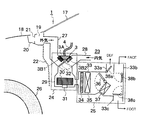
図1は本発明の実施の形態1に係る車両用灯具を備える車両の平面図、図2は同車両用灯具の灯体ユニットの縦断面図、図3は同車両用灯具の光源ユニットの放熱構造を示す車両前部の構成図である。
<Embodiment 1>
1 is a plan view of a vehicle including a vehicle lamp according to Embodiment 1 of the present invention, FIG. 2 is a longitudinal sectional view of a lamp unit of the vehicle lamp, and FIG. 3 is a heat dissipation of a light source unit of the vehicle lamp. It is a block diagram of the vehicle front part which shows a structure.

図1に示す車両1においては、車体の前部左右に灯体ユニット2が配置されており、エンジンルーム23(図3参照)内の左側には、左右の灯体ユニット2とは別設された光源ユニット3が配置されている。ここで、本発明に係る車両用灯具はヘッドランプであって、左右の灯体ユニット2と光源ユニット3によって構成されており、光源ユニット3は、光伝播手段である左右の光ファイバ4によって左右の灯体ユニット2にそれぞれ接続されている。   In the vehicle 1 shown in FIG. 1, lamp units 2 are arranged on the left and right sides of the front part of the vehicle body, and are provided separately from the left and right lamp units 2 on the left side in the engine room 23 (see FIG. 3). A light source unit 3 is arranged. Here, the vehicular lamp according to the present invention is a headlamp, and is composed of a left and right lamp unit 2 and a light source unit 3. The light source unit 3 is left and right by left and right optical fibers 4 serving as light propagation means. Are connected to each of the lamp units 2.

各灯体ユニット2は、図2に示すように、ハウジング5とその前面開口部を覆う透明なアウタレンズ6によって画成された灯室7内に、ランプモジュール8とエクステンション9を収容して構成されている。ここで、光源モジュール8は、光軸調整機構10によってハウジング5に固定された支持筐体11、該支持筐体11に固定された集光コリメータレンズ12とフランジ13、該フランジ13の中央に固定された支持基板14、該支持基板14上に実装された光変換素子15、配光制御用のレンズ16によって構成されている。尚、支持筐体11は、アルミニウムや銅等の熱伝導率の高い金属によって構成されている。又、光変換素子15は、光を特定の波長の光に変換するための蛍光体によって構成されている。更に、光源ユニット3から光ファイバ4を介して放出される光が白色である場合には、光変換素子15は必須ではない。   As shown in FIG. 2, each lamp unit 2 is configured such that a lamp module 8 and an extension 9 are accommodated in a lamp chamber 7 defined by a housing 5 and a transparent outer lens 6 covering a front opening of the housing 5. ing. Here, the light source module 8 is fixed to the support housing 11 fixed to the housing 5 by the optical axis adjusting mechanism 10, the condensing collimator lens 12 fixed to the support housing 11 and the flange 13, and the center of the flange 13. The support substrate 14, the light conversion element 15 mounted on the support substrate 14, and the lens 16 for light distribution control. The support housing 11 is made of a metal having high thermal conductivity such as aluminum or copper. The light conversion element 15 is composed of a phosphor for converting light into light of a specific wavelength. Furthermore, when the light emitted from the light source unit 3 via the optical fiber 4 is white, the light conversion element 15 is not essential.

ところで、図3に示すように、車両のフロントガラス17とエンジンフード18との間には外気導入口19が開口しており、この外気導入口19には、カウル20から垂直に立設されたカウルバー21が臨んでいる。そして、車両前部のダッシュパネル22によって区画されたエンジンルーム23内には、送風機ユニット24と空調ユニット25が配置されている。尚、図3において、26は左右の前輪(図3には一方のみ図示)である。   Incidentally, as shown in FIG. 3, an outside air introduction port 19 is opened between the vehicle windshield 17 and the engine hood 18, and the outside air introduction port 19 is erected vertically from the cowl 20. Cowl bar 21 is facing. A blower unit 24 and an air conditioning unit 25 are arranged in the engine room 23 partitioned by the dash panel 22 at the front of the vehicle. In FIG. 3, reference numeral 26 denotes left and right front wheels (only one is shown in FIG. 3).

上記送風機ユニット24は、一端がダッシュパネル22を介して外気導入口19に連なる外気ダクト27と一端が車室内に開口する内気ダクト28とが合流して構成されたファンダクト29の内部に配置されたファン30と、該ファン30を回転駆動するファンモータ31を備えている。尚、外気ダクト27と内気ダクト28との合流部には、回動可能な内外気切替ドア32が配置されている。   The blower unit 24 is disposed inside a fan duct 29 having one end connected to the outside air introduction port 19 through the dash panel 22 and an inside air duct 28 having one end opening into the vehicle interior. And a fan motor 31 that rotationally drives the fan 30. In addition, a rotatable inside / outside air switching door 32 is disposed at a junction between the outside air duct 27 and the inside air duct 28.

又、前記空調ユニット25は、送風機ユニット24のファンダクト29に連なる空調ダクト33内に、車両前方(図3の左方)からフィルタ34、蒸発器35、回動可能なエアミックスドア36及びヒーターコア37を順次収容して構成されている。ここで、空調ダクト33からは、フロントガラス17の内側(DEF)に向けて空気を供給するダクト33aと、乗員の顔(FACE)に向けて空気を供給するダクト33bと、乗員の足(FOOT)に向けて空気を供給するダクト3cが分岐しており、各ダクト33a〜33cの分岐部には、各ダクト33a〜33cを開閉するための回動可能なドア38a〜38cがそれぞれ設けられている。   The air conditioning unit 25 includes a filter 34, an evaporator 35, a rotatable air mix door 36, and a heater in the air conditioning duct 33 connected to the fan duct 29 of the blower unit 24 from the front of the vehicle (left side in FIG. 3). The core 37 is sequentially accommodated. Here, from the air conditioning duct 33, a duct 33a that supplies air toward the inside (DEF) of the windshield 17, a duct 33b that supplies air toward the occupant's face (FACE), and the occupant's feet (FOOT) ) For supplying air toward the air), and branching portions of the ducts 33a to 33c are provided with rotatable doors 38a to 38c for opening and closing the ducts 33a to 33c, respectively. Yes.

ところで、ヘッドランプとして使用される本実施の形態に係る車両用灯具は、図2に示す左右の灯体ユニット2(図2には一方のみ図示)と図3に示す光源ユニット3によって構成されているが、この光源ユニット3は、例えば青色光を発するLD(レーザーダイオード)やLED(発光ダイオード)等の不図示の半導体発光素子を備えた光源部3Aと、該光源部3Aの半導体発光素子が発生する熱を放熱するための放熱部としてのヒートシンク3Bによって構成されている。   By the way, the vehicular lamp according to the present embodiment used as a headlamp is composed of left and right lamp units 2 (only one is shown in FIG. 2) and a light source unit 3 shown in FIG. However, the light source unit 3 includes a light source unit 3A including a semiconductor light emitting element (not shown) such as an LD (laser diode) or LED (light emitting diode) that emits blue light, and a semiconductor light emitting element of the light source unit 3A. It is constituted by a heat sink 3B as a heat radiating part for radiating generated heat.

而して、本実施の形態は、光源ユニット3のヒートシンク3Bを外気ダクト27内に配置したことを特徴としており、このヒートシンク3Bには、外気ダクト27を介して光源部3Aが密着している。尚、光源部3Aは、光ファイバ4によって左右の灯体ユニット2にそれぞれ接続されている(図1参照)。   Thus, the present embodiment is characterized in that the heat sink 3B of the light source unit 3 is disposed in the outside air duct 27, and the light source section 3A is in close contact with the heat sink 3B via the outside air duct 27. . The light source unit 3A is connected to the left and right lamp units 2 by optical fibers 4 (see FIG. 1).

以上のように構成された車両用灯具において、光源ユニット3の光源部3Aに設けられた不図示の半導体発光素子にバッテリ等の不図示の電源から電流が供給されて該半導体発光素子が発光すると、その光は、光ファイバ4を経て左右の灯体ユニット2へと送られる。すると、図2に示す各灯体ユニット2においては、光は、集光コリメータレンズ12によって集光された後、光変換素子15によって特定の波長の光(例えば、青色光が黄色光(最終的には白色光))に変換される。そして、特定の波長の光は、レンズ16を通過することによって配光が制御され、透明なアウタレンズ6を透過して車両前方へと照射されるため、車両用灯具は、ヘッドランプとしての機能を果たす。   In the vehicular lamp configured as described above, when a current is supplied from a power source (not shown) such as a battery to a semiconductor light emitting device (not shown) provided in the light source unit 3A of the light source unit 3, the semiconductor light emitting device emits light. The light is sent to the right and left lamp units 2 through the optical fiber 4. Then, in each lamp unit 2 shown in FIG. 2, after the light is condensed by the condensing collimator lens 12, light of a specific wavelength (for example, blue light is converted into yellow light (final light) Is converted to white light)). The light of a specific wavelength is controlled by passing through the lens 16 and is transmitted to the front of the vehicle through the transparent outer lens 6, so that the vehicular lamp has a function as a headlamp. Fulfill.

ところで、上述のように光源ユニット3の光源部3Aに設けられた半導体発光素子が発光すると熱が発生するが、この熱は、外気ダクト27を経てヒートシンク3Bへと伝導して該ヒートシンク3Bから放熱される。   By the way, heat is generated when the semiconductor light emitting element provided in the light source unit 3A of the light source unit 3 emits light as described above, but this heat is conducted to the heat sink 3B through the outside air duct 27 and radiated from the heat sink 3B. Is done.

而して、車室内への送風モードとして外気導入モードが選択されている場合には、内外気切替ドアが図3に実線にて示すように外気ダクト27を開き、内気ダクト28を閉じるため、送風機ユニット24のファン30の回転によって外気が外気導入口19から外気ダクト27へと導入される。そして、このとき空調ユニット25が駆動され、該空調ユニット25が冷房運転されている場合には、エアミックスドア36が図3に破線にて示す位置に切り替えられ、フィルタ34を通過する外気は、蒸発器35における液体冷媒の蒸発潜熱によって熱を奪われて冷やされ、冷気がダクト33a〜33cから車室内のフロントガラス17の内側、乗員の顔や足に向けて供給される。尚、冷気が供給される箇所の切り替えは、各ドア38a〜38cの開閉によってなされ、図3に示す例では、冷気は、フロントガラス17の内側と乗員の顔に向けて吹き付けられている。   Thus, when the outside air introduction mode is selected as the air blowing mode into the vehicle interior, the inside / outside air switching door opens the outside air duct 27 and closes the inside air duct 28 as shown by a solid line in FIG. The outside air is introduced from the outside air inlet 19 into the outside air duct 27 by the rotation of the fan 30 of the blower unit 24. At this time, when the air conditioning unit 25 is driven and the air conditioning unit 25 is in cooling operation, the air mix door 36 is switched to the position indicated by the broken line in FIG. Heat is taken away and cooled by the latent heat of vaporization of the liquid refrigerant in the evaporator 35, and the cold air is supplied from the ducts 33 a to 33 c toward the inside of the windshield 17 in the passenger compartment, the face and feet of the passenger. In addition, the location where the cold air is supplied is switched by opening and closing the doors 38a to 38c. In the example shown in FIG. 3, the cold air is blown toward the inside of the windshield 17 and the face of the passenger.

他方、空調ユニット25が暖房運転されている場合には、エアミックスドア36が図3に実線にて示す位置に切り替えられ、フィルタ34を通過した外気は、ヒーターコア37によって加熱されて暖気となり、この暖気は、車室内のフロントガラス17の内側、乗員の顔や足に向けて供給される。   On the other hand, when the air conditioning unit 25 is in a heating operation, the air mix door 36 is switched to the position shown by the solid line in FIG. 3, and the outside air that has passed through the filter 34 is heated by the heater core 37 to become warm air, This warm air is supplied to the inside of the windshield 17 in the passenger compartment, toward the passenger's face and feet.

而して、送風モードとして外気モードが選択されている場合には、外気が外気ダクト27を流れるが、本実施の形態では、光源ユニット3のヒートシンク3Bを外気ダクト27内に配置したため、この外気ダクト27を流れる外気によってヒートシンク3Bが強制空冷され、該ヒートシンク3Bからの放熱が促進される。このため、光源部3Aの半導体発光素子が効率良く冷却されてその温度上昇が低く抑えられ、該半導体発光素子の温度上昇に伴う発光効率と寿命の低下が防がれる。そして、本実施の形態では、車両に既設の外気ダクト27や送風機ユニット24、空調ユニット25等を利用するため、放熱構造の単純化と部品点数の削減が図られて軽量化とコストダウンが実現される。   Thus, when the outside air mode is selected as the air blowing mode, the outside air flows through the outside air duct 27. In the present embodiment, since the heat sink 3B of the light source unit 3 is disposed in the outside air duct 27, this outside air The heat sink 3B is forcibly cooled by the outside air flowing through the duct 27, and heat dissipation from the heat sink 3B is promoted. For this reason, the semiconductor light emitting element of the light source unit 3A is efficiently cooled and the temperature rise is suppressed to a low level, and the light emission efficiency and the lifetime are not reduced due to the temperature rise of the semiconductor light emitting element. In this embodiment, since the outside air duct 27, the blower unit 24, the air conditioning unit 25, and the like that are already installed in the vehicle are used, the heat dissipation structure is simplified and the number of parts is reduced, thereby realizing weight reduction and cost reduction. Is done.

又、車室内への送風モードとして内気循環モードが選択されている場合には、内外気切替ドア32が図3に破線にて示すように外気ダクト27を閉じ、内気ダクト28を開くため、送風機ユニット24のファン30の回転によって車室内の内気が内気ダクト28から空調ユニット25へと流入する。そして、前記と同様に冷房運転時には、蒸発器35を通過した冷気がダクト33a〜33cの何れかを通って車室内に導入されて車室の冷房に供され、暖房運転時には、ヒーターコア37によって加熱された暖気がダクト33a〜33cの何れかを通って車室内に導入されて車室の暖房に供される。   When the inside air circulation mode is selected as the air blowing mode to the vehicle interior, the inside / outside air switching door 32 closes the outside air duct 27 and opens the inside air duct 28 as shown by a broken line in FIG. The inside air of the passenger compartment flows into the air conditioning unit 25 from the inside air duct 28 by the rotation of the fan 30 of the unit 24. Similarly to the above, during the cooling operation, the cold air that has passed through the evaporator 35 is introduced into the passenger compartment through any of the ducts 33a to 33c and is used for cooling the passenger compartment. During the heating operation, the heater core 37 The heated warm air is introduced into the passenger compartment through any of the ducts 33a to 33c and used for heating the passenger compartment.

而して、送風モードとして内気循環モードが選択されているときには、外気ダクト27を外気が流れないため、外気ダクト27内に配置された光源ユニット3のヒートシンク3Bは、外気によって強制空冷されることはないが、空気の自然対流によってヒートシンク3Bからの放熱が促進されるため、光源部3Aに設けられた半導体発光素子が冷却されてその温度上昇が低く抑えられる。   Thus, when the inside air circulation mode is selected as the air blowing mode, the outside air does not flow through the outside air duct 27. Therefore, the heat sink 3B of the light source unit 3 disposed in the outside air duct 27 is forcibly cooled by the outside air. However, since heat dissipation from the heat sink 3B is promoted by natural convection of air, the semiconductor light emitting element provided in the light source unit 3A is cooled, and the temperature rise is suppressed low.

<実施の形態2>
次に、本発明の実施の形態2を図4に基づいて説明する。尚、図4は本発明の実施の形態2に係る車両用灯具の光源ユニットの放熱構造を示す車両前部の構成図であり、本図においては図3において示したものと同一要素には同一符号を付しており、以下、それらについての再度の説明は省略する。
<Embodiment 2>
Next, a second embodiment of the present invention will be described with reference to FIG. 4 is a configuration diagram of the front portion of the vehicle showing the heat dissipation structure of the light source unit of the vehicular lamp according to the second embodiment of the present invention. In this figure, the same elements as those shown in FIG. 3 are the same. Reference numerals are attached, and repetitive description thereof will be omitted below.

本実施の形態は、送風機ユニット24と空調ユニット25とを接続するダクト39から排気ダクト40を分岐させるとともに、その分岐部に、排気ダクト40を開閉するための排気ドア41を設けたことを特徴としており、他の構成は前記実施の形態1の構成と同じである。   The present embodiment is characterized in that an exhaust duct 40 is branched from a duct 39 connecting the blower unit 24 and the air conditioning unit 25, and an exhaust door 41 for opening and closing the exhaust duct 40 is provided at the branch portion. Other configurations are the same as those of the first embodiment.

而して、本実施の形態によれば、空調ユニット25を使用しないで(車室内の冷暖房を行わないで)光源ユニット3の放熱を行う場合に、ファン30の駆動時に車室内への送風を防ぐために排気ドア41を実線位置に切り替えて排気ダクト40を開くとともに、空調ユニット25への送風を遮断するようにしている。この場合、送風モードとして外気導入モードが選択されて内外気切替ドア32が実線位置にある状態では、ファン30によって吸引されて外気ダクト27を流れる外気によって光源ユニット3のヒートシンク3Bが強制空冷されるため、該ヒートシンク3Bからの放熱が促進されて半導体発光素子の温度上昇が抑えられ、前記実施の形態1と同様の効果が得られる。尚、排気ダクト40の排気口は、エンジンルーム23内若しくは車両後方に開口させることができる。   Thus, according to the present embodiment, when the heat radiation of the light source unit 3 is performed without using the air conditioning unit 25 (without cooling or heating the vehicle interior), the fan 30 is blown into the vehicle interior when the fan 30 is driven. In order to prevent this, the exhaust door 41 is switched to the solid line position, the exhaust duct 40 is opened, and the air blowing to the air conditioning unit 25 is blocked. In this case, when the outside air introduction mode is selected as the air blowing mode and the inside / outside air switching door 32 is in the solid line position, the heat sink 3B of the light source unit 3 is forcibly cooled by the outside air that is sucked by the fan 30 and flows through the outside air duct 27. Therefore, heat dissipation from the heat sink 3B is promoted, and the temperature rise of the semiconductor light emitting element is suppressed, and the same effect as in the first embodiment can be obtained. The exhaust port of the exhaust duct 40 can be opened in the engine room 23 or the rear of the vehicle.

<実施の形態3>
次に、本発明の実施の形態3を図5に基づいて説明する。尚、図5は本発明の実施の形態3に係る車両用灯具の光源ユニットの放熱構造を示す車両前部の構成図であり、本図においても図3において示したものと同一要素には同一符号を付しており、以下、それらについての再度の説明は省略する。
<Embodiment 3>
Next, Embodiment 3 of the present invention will be described with reference to FIG. FIG. 5 is a configuration diagram of the front portion of the vehicle showing the heat dissipation structure of the light source unit of the vehicular lamp according to the third embodiment of the present invention. In FIG. 5, the same elements as those shown in FIG. Reference numerals are attached, and repetitive description thereof will be omitted below.

本実施の形態は、光源ユニット3のヒートシンク3Bを内気ダクト28内に配置し、このヒートシンク3Bに内気ダクト28を介して光源部3Aを密着させたことを特徴としており、他の構成は前記実施の形態1の構成と同じである。   The present embodiment is characterized in that the heat sink 3B of the light source unit 3 is disposed in the inside air duct 28, and the light source unit 3A is in close contact with the heat sink 3B via the inside air duct 28. The configuration is the same as that of the first embodiment.

而して、本実施の形態によれば、送風モードとして内気循環モードが選択されている場合、ファン30の回転によって送風機ユニット24へと流れ込む内気によってヒートシンク3Bが強制空冷されるため、該ヒートシンク3Bの放熱性能が高められて光源部3Aの半導体発光素子が効果的に冷却され、該半導体発光素子の温度上昇が低く抑えられるという前記実施の形態1と同様の効果が得られる。   Thus, according to the present embodiment, when the inside air circulation mode is selected as the blowing mode, the heat sink 3B is forcibly cooled by the inside air that flows into the blower unit 24 by the rotation of the fan 30, so the heat sink 3B The heat radiation performance is improved, the semiconductor light emitting element of the light source section 3A is effectively cooled, and the same effect as in the first embodiment can be obtained that the temperature rise of the semiconductor light emitting element can be suppressed low.

<実施の形態4>
次に、本発明の実施の形態4を図6に基づいて説明する。尚、図6は本発明の実施の形態4に係る車両用灯具の光源ユニットの放熱構造を示す車両前部の構成図であり、本図においても図3において示したものと同一要素には同一符号を付しており、以下、それらについての再度の説明は省略する。
<Embodiment 4>
Next, a fourth embodiment of the present invention will be described with reference to FIG. FIG. 6 is a configuration diagram of the front portion of the vehicle showing the heat dissipation structure of the light source unit of the vehicular lamp according to the fourth embodiment of the present invention. In FIG. 6, the same elements as those shown in FIG. Reference numerals are attached, and repetitive description thereof will be omitted below.

本実施の形態は、光源ユニット3の2つのヒートシンク3B1,3B2を外気ダクト27内と内気ダクト28内にそれぞれ設置し、両ヒートシンク3B1,3B2に1つの光源部3Aを密着させたことを特徴としており、他の構成は前記実施の形態1の構成と同じである。   The present embodiment is characterized in that two heat sinks 3B1 and 3B2 of the light source unit 3 are installed in the outside air duct 27 and the inside air duct 28, respectively, and one light source unit 3A is brought into close contact with both the heat sinks 3B1 and 3B2. Other configurations are the same as those of the first embodiment.

而して、本実施の形態では、送風モードとして外気導入モードが選択されている場合には、外気ダクト27を流れる外気によって一方のヒートシンク3B1を強制空冷することができ、内気循環モードが選択されている場合には、内気ダクト28を流れる内気によって他方のヒートシンク3B2を強制空冷することができる。   Thus, in the present embodiment, when the outside air introduction mode is selected as the air blowing mode, the one heat sink 3B1 can be forcibly cooled by the outside air flowing through the outside air duct 27, and the inside air circulation mode is selected. If this is the case, the other heat sink 3B2 can be forcibly cooled by the inside air flowing through the inside air duct 28.

従って、本実施の形態によれば、送風モードとして外気導入モードと内気循環モードの何れが選択されている場合であっても、ヒートシンク3B1,3B2の一方を強制空冷することができるため、光源部3Aの半導体発光素子を効果的に冷却してその温度上昇を低く抑えることができる。   Therefore, according to the present embodiment, since either the outside air introduction mode or the inside air circulation mode is selected as the air blowing mode, one of the heat sinks 3B1 and 3B2 can be forcibly air-cooled. It is possible to effectively cool the 3A semiconductor light emitting device and to suppress the temperature rise.

そして、本実施の形態では、2つのヒートシンク3B1,3B2を用いたため、各ヒートシンク3B1,3B2のサイズを半分程度に小型化することができ、外気ダクト27と内気ダクト28との圧力損失が小さく抑えられ、これらの外気ダクト27を流れる外気と内気ダクト28を流れる内気の流速の低下を抑えることができるという効果も得られる。   In this embodiment, since the two heat sinks 3B1 and 3B2 are used, the size of each of the heat sinks 3B1 and 3B2 can be reduced to about half, and the pressure loss between the outside air duct 27 and the inside air duct 28 is kept small. In addition, it is possible to suppress the decrease in the flow velocity of the outside air flowing through the outside air duct 27 and the inside air flowing through the inside air duct 28.

<実施の形態5>
次に、本発明の実施の形態5を図7に基づいて説明する。尚、図7は本発明の実施の形態5に係る車両用灯具の光源ユニットの放熱構造を示す車両前部の構成図であり、本図においても図3において示したものと同一要素には同一符号を付しており、以下、それらについての再度の説明は省略する。
<Embodiment 5>
Next, a fifth embodiment of the present invention will be described with reference to FIG. FIG. 7 is a configuration diagram of the front portion of the vehicle showing the heat dissipation structure of the light source unit of the vehicular lamp according to the fifth embodiment of the present invention. In FIG. 7, the same elements as those shown in FIG. Reference numerals are attached, and repetitive description thereof will be omitted below.

本実施の形態は、光源ユニット3のヒートシンク3Bを車両に開口する外気導入口19のカウル20付近に配置し、このヒートシンク3Bに光源部3Aを密着させたことを特徴としており、他の構成は前記実施の形態1の構成と同じである。   The present embodiment is characterized in that the heat sink 3B of the light source unit 3 is disposed in the vicinity of the cowl 20 of the outside air inlet 19 that opens to the vehicle, and the light source unit 3A is in close contact with the heat sink 3B. The configuration is the same as that of the first embodiment.

而して、本実施の形態では、ファン30が回転駆動されているときには、外気が送風機ユニット24に吸い込まれる際に生じる外気導入口19付近の空気の流れによってヒートシンク3Bが強制空冷されるため、該ヒートシンク3Bからの放熱が促進されて光源部3Aの半導体発光素子の温度上昇が低く抑えられる。   Thus, in the present embodiment, when the fan 30 is rotationally driven, the heat sink 3B is forcibly air-cooled by the air flow in the vicinity of the outside air inlet 19 generated when outside air is sucked into the blower unit 24. The heat radiation from the heat sink 3B is promoted, and the temperature rise of the semiconductor light emitting element of the light source unit 3A is suppressed to a low level.

又、ファン30が停止しているときには、車両の走行中は走行風によってヒートシンク3Bが強制空冷され、車両が停止しているときには、空気の自然対流によってヒートシンク3Bが冷却されるため、光源部3Aの半導体発光素子の温度上昇が低く抑えられる。   Further, when the fan 30 is stopped, the heat sink 3B is forcibly air-cooled by the traveling wind while the vehicle is traveling, and when the vehicle is stopped, the heat sink 3B is cooled by natural convection of air, so that the light source unit 3A The temperature rise of the semiconductor light emitting device can be kept low.

<実施の形態6>
次に、本発明の実施の形態6を図8に基づいて説明する。尚、図8は本発明の実施の形態6に係る車両用灯具の光源ユニットの放熱構造を示す車両前部の構成図であり、図9は光源ユニットの斜視図であり、これらの図においても図3において示したものと同一要素には同一符号を付しており、以下、それらについての再度の説明は省略する。
<Embodiment 6>
Next, a sixth embodiment of the present invention will be described with reference to FIG. 8 is a configuration diagram of the front portion of the vehicle showing the heat dissipation structure of the light source unit of the vehicular lamp according to the sixth embodiment of the present invention, and FIG. 9 is a perspective view of the light source unit. The same elements as those shown in FIG. 3 are denoted by the same reference numerals, and description thereof will be omitted below.

本実施の形態は、外気ダクト27の開口部に、該外気ダクト27への水の浸入を阻止する遮水ルーバとして機能するヒートシンク3Bと、該ヒートシンク3Bの左右に固定された光源部3Aを配置したことを特徴としており、他の構成は前記実施の形態1の構成と同じである。ここで、ヒートシンク3Bは、適当な間隔で上下に重ねられた複数枚(図示例では、5枚)の放熱板3aによって構成されている。又、左右の光源ユニット3Aは、光ファイバ4によって左右の灯体ユニット2(図2参照)にそれぞれ接続されている。   In the present embodiment, a heat sink 3B that functions as a water-blocking louver that prevents water from entering the outside air duct 27 and a light source unit 3A that is fixed to the left and right of the heat sink 3B are disposed at the opening of the outside air duct 27. The other structure is the same as that of the first embodiment. Here, the heat sink 3B is configured by a plurality of (five in the illustrated example) heat radiating plates 3a that are vertically stacked at an appropriate interval. The left and right light source units 3A are connected to the left and right lamp units 2 (see FIG. 2) by optical fibers 4, respectively.

而して、本実施の形態では、ファン30が回転駆動されているときには、外気ダクト27へと流入する外気がルーバ状のヒートシンク3Bを通過することによって該ヒートシンク3Bが強制空冷されるため、該ヒートシンク3Bからの放熱が促進されて左右の光源部3Aの各半導体発光素子の温度上昇が低く抑えられる。   Thus, in the present embodiment, when the fan 30 is driven to rotate, the outside air flowing into the outside air duct 27 passes through the louver-like heat sink 3B, so that the heat sink 3B is forcibly cooled by air. Heat dissipation from the heat sink 3B is promoted, and the temperature rise of each semiconductor light emitting element of the left and right light source portions 3A is suppressed to a low level.

又、ファン30が停止しているときには、車両の走行中は走行風によってヒートシンク3Bが強制空冷され、車両が停止しているときには、空気の自然対流によってヒートシンク3Bが冷却されるため、左右の光源部3Aの各半導体発光素子の温度上昇が低く抑えられる。   Further, when the fan 30 is stopped, the heat sink 3B is forcibly air-cooled by the traveling wind while the vehicle is traveling, and when the vehicle is stopped, the heat sink 3B is cooled by the natural convection of the air. The temperature rise of each semiconductor light emitting element of the part 3A can be suppressed low.

<実施の形態7>
次に、本発明の実施の形態7を図10に基づいて説明する。尚、図10は本発明の実施の形態7に係る車両用灯具の光源ユニットの放熱構造を示す車両前部の構成図であり、本図においても図3において示したものと同一要素には同一符号を付しており、以下、それらについての再度の説明は省略する。
<Embodiment 7>
Next, a seventh embodiment of the present invention will be described with reference to FIG. FIG. 10 is a configuration diagram of the front portion of the vehicle showing the heat dissipation structure of the light source unit of the vehicular lamp according to the seventh embodiment of the present invention. In FIG. 10, the same elements as those shown in FIG. Reference numerals are attached, and repetitive description thereof will be omitted below.

本実施の形態は、光源ユニット3のヒートシンク3Bを外気ダクト27内に配置し、このヒートシンク3Bから離れた前輪26のタイヤハウス付近に光源部3Aを配置し、これらのヒートシンク3Bと光源部3Aとを熱輸送手段であるヒートパイプ42によって熱的に接続したことを特徴としており、他の構成は前記実施の形態と同じである。   In the present embodiment, the heat sink 3B of the light source unit 3 is disposed in the outside air duct 27, the light source unit 3A is disposed near the tire house of the front wheel 26 away from the heat sink 3B, and the heat sink 3B, the light source unit 3A, Are thermally connected by a heat pipe 42 which is a heat transport means, and the other configuration is the same as that of the above embodiment.

而して、本実施の形態では、光源ユニット3の光源部3Aに設けられた半導体発光素子が発生する熱は、ヒートパイプ42を経てヒートシンク3Bに伝導するが、ヒートシンク3Bは、前記実施の形態1と同様に外気ダクト27内に配置されているため、外気ダクト27を流れる外気によって強制空冷され、或いは空気の自然対流によって冷却されてその放熱性能が高められる。この結果、光源部3Aの半導体発光素子の温度上昇が低く抑えられるという効果が得られる。   Thus, in the present embodiment, the heat generated by the semiconductor light emitting element provided in the light source unit 3A of the light source unit 3 is conducted to the heat sink 3B via the heat pipe 42. Since it is arranged in the outside air duct 27 in the same manner as 1, it is forcibly air-cooled by the outside air flowing through the outside air duct 27, or is cooled by natural convection of air, so that its heat radiation performance is enhanced. As a result, the effect that the temperature rise of the semiconductor light emitting element of the light source unit 3A can be suppressed low can be obtained.

尚、本実施の形態に係る放熱構造は、車両スペースの都合上、光源ユニット3の光源部3Aをヒートシンク3Bに密着させて配置することができない場合に有効である。この場合、光源部3Aは、エンジンルーム23からの熱を受けないように断熱構造とすることが望ましい。   Note that the heat dissipation structure according to the present embodiment is effective when the light source unit 3A of the light source unit 3 cannot be disposed in close contact with the heat sink 3B due to vehicle space. In this case, it is desirable that the light source unit 3 </ b> A has a heat insulating structure so as not to receive heat from the engine room 23.

<実施の形態8>
次に、本発明の実施の形態8を図11に基づいて説明する。尚、図11は本発明の実施の形態8に係る車両用灯具の光源ユニットの放熱構造を示す車両前部の構成図であり、本図においても図3において示したものと同一要素には同一符号を付しており、以下、それらについての再度の説明は省略する。
<Eighth embodiment>
Next, an eighth embodiment of the present invention will be described with reference to FIG. FIG. 11 is a configuration diagram of the front portion of the vehicle showing the heat dissipation structure of the light source unit of the vehicular lamp according to the eighth embodiment of the present invention. In FIG. 11, the same elements as those shown in FIG. Reference numerals are attached, and repetitive description thereof will be omitted below.

本実施の形態は、光源ユニット3のヒートシンク3Bを、外気ダクト27と内気ダクト28との合流部であって、内外気切替ドア32の下流側に配置し、このヒートシンク3Bに光源部3Aを密着させたことを特徴としており、他の構成は前記実施の形態1の構成と同じである。   In the present embodiment, the heat sink 3B of the light source unit 3 is arranged at the junction of the outside air duct 27 and the inside air duct 28 at the downstream side of the inside / outside air switching door 32, and the light source 3A is in close contact with the heat sink 3B. The other structure is the same as that of the first embodiment.

而して、本実施の形態によれば、送風モードとして外気導入モードが選択されて内外気切替ドア32が破線にて示す位置にある場合には、ヒートシンク3Bは、外気ダクト27を流れる外気によって強制空冷され、内気循環モードが選択されて内外気切替ドア32が実線にて示す位置にある場合には、ヒートシンク3Bは、内気ダクト28を流れる内気によって強制空冷される。   Thus, according to the present embodiment, when the outside air introduction mode is selected as the air blowing mode and the inside / outside air switching door 32 is at the position indicated by the broken line, the heat sink 3B is caused by the outside air flowing through the outside air duct 27. When forced air cooling is performed and the inside air circulation mode is selected and the inside / outside air switching door 32 is at the position indicated by the solid line, the heat sink 3B is forcibly air cooled by the inside air flowing through the inside air duct 28.

従って、本実施の形態においては、前記実施の形態4と同様に、送風モードとして外気導入モードと内気循環モードの何れが選択されている場合であっても、ヒートシンク3Bは外気又は内気の何れかによって強制空冷されるため、光源部3Aの半導体発光素子を効果的に冷却してその温度上昇を低く抑えることができるという効果が得られる。   Therefore, in the present embodiment, as in the fourth embodiment, the heat sink 3B is either outside air or inside air, regardless of whether the outside air introduction mode or the inside air circulation mode is selected as the air blowing mode. Therefore, the semiconductor light emitting element of the light source unit 3A can be effectively cooled to suppress an increase in temperature.

<実施の形態9>
次に、本発明の実施の形態9を図12に基づいて説明する。尚、図12は本発明の実施の形態9に係る車両用灯具の光源ユニットの放熱構造を示す車両前部の構成図であり、本図においても図3において示したものと同一要素には同一符号を付しており、以下、それらについての再度の説明は省略する。
<Embodiment 9>
Next, Embodiment 9 of the present invention will be described with reference to FIG. FIG. 12 is a configuration diagram of the front portion of the vehicle showing the heat dissipation structure of the light source unit of the vehicular lamp according to the ninth embodiment of the present invention. In FIG. 12, the same elements as those shown in FIG. Reference numerals are attached, and repetitive description thereof will be omitted below.

本実施の形態は、内外気2層式の空調ユニット25と送風機ユニット24とを接続するダクト39内を内外気仕切板43によって仕切られた外気通路39aと内気通路39bに光源ユニット3のヒートシンク3B1,3B2をそれぞれ配置し、両ヒートシンク3B1,3B2の間に光源部3Aを配置したことを特徴としている。ここで、ダクト39内の外気通路39aと内気通路39bは、外気ダクト27と内気ダクト28にそれぞれ連通しており、内気ダクト28の開口部には、該内気ダクト28を開閉する内気ドア44が回動可能に設けられている。   In the present embodiment, the heat sink 3B1 of the light source unit 3 is divided into an outside air passage 39a and an inside air passage 39b in which a duct 39 connecting the inside / outside air two-layer air conditioning unit 25 and the blower unit 24 is partitioned by an inside / outside air partition plate 43. , 3B2 are arranged, and the light source part 3A is arranged between the heat sinks 3B1, 3B2. Here, the outside air passage 39 a and the inside air passage 39 b in the duct 39 communicate with the outside air duct 27 and the inside air duct 28, respectively, and an inside air door 44 that opens and closes the inside air duct 28 is provided at the opening of the inside air duct 28. It is provided so that rotation is possible.

而して、送風モードとして外気導入モードが選択されている場合には、内外気切替ドア32が破線にて示すように開き、内気ドア44が実線にて示すように閉じているため、ファン30によって外気ダクト27へと導入される外気は、外気ダクト27からダクト39内の外気通路39aを通って空調ユニット25へと送り込まれる。従って、外気通路39aに配置された一方のヒートシンク3B1が外気によって強制空冷されてその放熱性能が高められる。このため、光源部3Aの半導体発光素子が効果的に冷却されてその温度上昇が低く抑えられる。   Thus, when the outside air introduction mode is selected as the blowing mode, the inside / outside air switching door 32 is opened as indicated by a broken line, and the inside air door 44 is closed as indicated by a solid line. The outside air introduced into the outside air duct 27 is sent from the outside air duct 27 to the air conditioning unit 25 through the outside air passage 39a in the duct 39. Accordingly, one of the heat sinks 3B1 disposed in the outside air passage 39a is forcibly air-cooled by the outside air, and the heat dissipation performance is improved. For this reason, the semiconductor light emitting element of the light source part 3A is effectively cooled, and the temperature rise is suppressed low.

他方、送風モードとして内気循環モードが選択されている場合には、内外気切替ドア32が実線にて示すように閉じ、内気ドア44が破線にて示すように開いているため、ファン30によって内気ダクト28へと導入される内気は、内気ダクト28からダクト39内の内気通路39bを通って空調ユニット25へと送り込まれる。従って、内気通路39bに配置された他方のヒートシンク3B2が内気によって強制空冷されてその放熱性能が高められる。このため、光源部3Aの半導体発光素子が効果的に冷却されてその温度上昇が低く抑えられる。   On the other hand, when the inside air circulation mode is selected as the air blowing mode, the inside / outside air switching door 32 is closed as indicated by a solid line and the inside air door 44 is open as indicated by a broken line. The inside air introduced into the duct 28 is sent from the inside air duct 28 to the air conditioning unit 25 through the inside air passage 39b in the duct 39. Accordingly, the other heat sink 3B2 disposed in the inside air passage 39b is forcibly air-cooled by the inside air, and the heat dissipation performance is improved. For this reason, the semiconductor light emitting element of the light source part 3A is effectively cooled, and the temperature rise is suppressed low.

従って、本実施の形態によれば、前記実施の形態4,8と同様に、送風モードとして外気導入モードと内気循環モードの何れが選択されている場合であっても、ヒートシンク3B1,3B2の一方を強制空冷することができるため、光源部3Aの半導体発光素子を効果的に冷却してその温度上昇を低く抑えることができるという効果が得られる。   Therefore, according to the present embodiment, as in the fourth and eighth embodiments, one of the heat sinks 3B1 and 3B2 can be used regardless of whether the outside air introduction mode or the inside air circulation mode is selected as the air blowing mode. Therefore, the semiconductor light emitting element of the light source unit 3A can be effectively cooled to suppress the temperature rise to a low level.

1 車両
2 灯体ユニット
3 光源ユニット
3A 光源ユニットの光源部
3B 光源ユニットのヒートシンク(放熱部)
4 光ファイバ(光伝播手段)
5 ハウジング
6 アウタレンズ
7 灯室
8 ランプモジュール
9 エクステンション
10 光軸調整機構
11 支持筐体
12 集光コリメータレンズ
13 フランジ
14 支持基板
15 光変換素子
16 レンズ
17 フロントガラス
18 エンジンフード
19 外気導入口
20 カウル
21 カウルバー
22 ダッシュパネル
23 エンジンルーム
24 送風機ユニット
25 空調ユニット
26 前輪
27 外気ダクト(通風路)
28 内気ダクト(通風路)
29 ファンダクト
30 ファン
31 ファンモータ
32 内外気切替ドア
33 空調ダクト
34 フィルタ
35 蒸発器
36 エアミックスドア
37 ヒーターコア
38a〜38c ドア
39 ダクト
39a ダクトの外気通路
39b ダクトの内気通路
40 排気ダクト
41 排気ドア
42 ヒートパイプ(熱輸送手段)
43 内外気仕切板
44 内気ドア
DESCRIPTION OF SYMBOLS 1 Vehicle 2 Lamp body unit 3 Light source unit 3A Light source part of light source unit 3B Heat sink (heat radiation part) of light source unit
4 Optical fiber (light propagation means)
DESCRIPTION OF SYMBOLS 5 Housing 6 Outer lens 7 Lamp chamber 8 Lamp module 9 Extension 10 Optical axis adjustment mechanism 11 Support housing 12 Condensing collimator lens 13 Flange 14 Support substrate 15 Light conversion element 16 Lens 17 Front glass 18 Engine hood 19 Outside air introduction port 20 Cowl 21 Cowl bar 22 Dash panel 23 Engine room 24 Blower unit 25 Air conditioning unit 26 Front wheel 27 Outside air duct (ventilation path)
28 Inside air duct (ventilation path)
DESCRIPTION OF SYMBOLS 29 Fan duct 30 Fan 31 Fan motor 32 Inside / outside air switching door 33 Air conditioning duct 34 Filter 35 Evaporator 36 Air mix door 37 Heater core 38a-38c Door 39 Duct 39a Duct outside air passage 39b Duct inside air passage 40 Exhaust duct 41 Exhaust door 42 Heat pipe (heat transport means)
43 Inside / outside air partition plate 44 Inside air door

Claims (11)

配光制御用のレンズを含むランプモジュールを備えた灯体ユニットと、
前記灯体ユニットとは別設され、光源である半導体発光素子を含む光源部と、該光源部で発生する熱を放熱する放熱部を備えた光源ユニットと、
によって構成され、該灯体ユニットと前記光源ユニットとを光伝播手段によって接続して成る車両用灯具において、
前記光源ユニットの放熱部を、車両の空調ユニットに連なる通風路に配置したことを特徴とする車両用灯具。
A lamp unit including a lamp module including a lens for light distribution control;
A light source unit that is provided separately from the lamp unit and includes a semiconductor light emitting element that is a light source, and a light source unit that dissipates heat generated by the light source unit,
In a vehicle lamp comprising the lamp unit and the light source unit connected by a light propagation means,
A vehicular lamp, wherein the heat radiating portion of the light source unit is disposed in a ventilation path connected to an air conditioning unit of the vehicle.
前記放熱部を、前記空調ユニットに外気を導入する外気ダクト内に配置したことを特徴とする請求項1に記載の車両用灯具。   The vehicular lamp according to claim 1, wherein the heat dissipating part is disposed in an outside air duct that introduces outside air into the air conditioning unit. 前記放熱部を、前記空調ユニットに内気を導入する内気ダクト内に配置したことを特徴とする請求項1に記載の車両用灯具。   The vehicular lamp according to claim 1, wherein the heat dissipating unit is disposed in an inside air duct that introduces inside air into the air conditioning unit. 前記光源ユニットの放熱部を、前記空調ユニットに外気を導入する外気ダクト内と内気を導入する内気ダクト内にそれぞれ配置したことを特徴とする請求項1に記載の車両用灯具。   2. The vehicular lamp according to claim 1, wherein the heat radiating portion of the light source unit is disposed in an outside air duct that introduces outside air into the air conditioning unit and in an inside air duct that introduces inside air. 前記放熱部を、車両に開口する外気導入口のカウル付近に配置したことを特徴とする請求項1に記載の車両用灯具。   The vehicular lamp according to claim 1, wherein the heat dissipating part is disposed in the vicinity of a cowl of an outside air inlet opening in the vehicle. 前記放熱部を、前記空調ユニットに外気を導入する外気ダクトの前記外気導入口への開口部に設けられた遮熱ルーバとして構成したことを特徴とする請求項5に記載の車両用灯具。   The vehicular lamp according to claim 5, wherein the heat radiating unit is configured as a heat shield louver provided at an opening to the outside air introduction port of an outside air duct that introduces outside air into the air conditioning unit. 前記放熱部を、車両の空調ユニットに外気を導入する外気ダクトと内気を導入する内気ダクトとの合流部に設けられた送風機ユニット内に配置したことを特徴とする請求項1に記載の車両用灯具。   2. The vehicle according to claim 1, wherein the heat dissipating unit is arranged in a blower unit provided at a junction of an outside air duct that introduces outside air to an air conditioning unit of the vehicle and an inside air duct that introduces inside air. Light fixture. 前記放熱部を、車両の空調ユニット内の内外気仕切板によって仕切られた外気通路と内気通路にそれぞれ配置したことを特徴とする請求項1に記載の車両用灯具。   The vehicular lamp according to claim 1, wherein the heat radiating portion is disposed in an outside air passage and an inside air passage that are partitioned by an inside / outside air partition plate in an air conditioning unit of the vehicle. 前記送風機ユニットと前記空調ユニットとを接続するダクトに、排気ダクトを更に設けたことを特徴とする請求項7に記載の車両用灯具。   8. The vehicular lamp according to claim 7, further comprising an exhaust duct provided in a duct connecting the blower unit and the air conditioning unit. 前記光源部と前記放熱部とを別設し、両者を熱輸送手段によって熱的に接続したことを特徴とする請求項1〜9の何れかに記載の車両用灯具。   The vehicular lamp according to any one of claims 1 to 9, wherein the light source unit and the heat radiating unit are separately provided, and both are thermally connected by heat transport means. 前記光源ユニットから前記光伝播手段を介して伝播する光は青色光であり、前記灯体ユニットは、前記青色光を黄色光に変換する蛍光体を含むことを特徴とする請求項1〜10の何れかに記載の車両用灯具。
The light propagating from the light source unit through the light propagation means is blue light, and the lamp unit includes a phosphor that converts the blue light into yellow light. The vehicle lamp according to any one of the above.
JP2016078631A 2016-04-11 2016-04-11 Vehicular lighting fixture Pending JP2017191638A (en)

Priority Applications (1)

Application Number Priority Date Filing Date Title
JP2016078631A JP2017191638A (en) 2016-04-11 2016-04-11 Vehicular lighting fixture

Applications Claiming Priority (1)

Application Number Priority Date Filing Date Title
JP2016078631A JP2017191638A (en) 2016-04-11 2016-04-11 Vehicular lighting fixture

Publications (1)

Publication Number Publication Date
JP2017191638A true JP2017191638A (en) 2017-10-19

Family

ID=60084750

Family Applications (1)

Application Number Title Priority Date Filing Date
JP2016078631A Pending JP2017191638A (en) 2016-04-11 2016-04-11 Vehicular lighting fixture

Country Status (1)

Country Link
JP (1) JP2017191638A (en)

Cited By (1)

* Cited by examiner, † Cited by third party
Publication number Priority date Publication date Assignee Title
JP7338401B2 (en) 2019-10-30 2023-09-05 市光工業株式会社 vehicle lamp

Cited By (1)

* Cited by examiner, † Cited by third party
Publication number Priority date Publication date Assignee Title
JP7338401B2 (en) 2019-10-30 2023-09-05 市光工業株式会社 vehicle lamp

Similar Documents

Publication Publication Date Title
JP5160992B2 (en) Vehicle lighting
CN103339439B (en) Light emitting semiconductor module and car light
JP5923271B2 (en) Headlamp assembly and automobile having the same
JP5331418B2 (en) Illumination device provided with semiconductor light source
EP2733412B1 (en) Vehicular lamp
JP5342553B2 (en) Vehicle lighting
US8297805B2 (en) Device for cooling an optical module for a motor vehicle headlight
JP4822443B2 (en) Vehicle headlamp
JP2008226843A (en) Lighting or signal device for automotive having outer wall having heat exchanger
CN107448860B (en) Motor vehicle lighting and/or signaling device provided with a light-emitting module cooled by means of an airflow generator
JP4915928B2 (en) Vehicle headlamp
JP4661740B2 (en) LED lights for vehicles
US10746371B2 (en) Vehicular lamp
JP2018100011A (en) Antifreezing device for vehicle headlight
JP2017191638A (en) Vehicular lighting fixture
US10851964B2 (en) Lighting fixture for vehicle
JP6811600B2 (en) Heat dissipation structure of vehicle lighting equipment
RU2706627C1 (en) Vehicle cooling assembly and vehicle
JP2018098086A (en) Heat radiation structure for vehicular lighting
JP6960746B2 (en) Heat dissipation structure of vehicle lighting equipment
JP2023133120A (en) Vehicle lamp fitting
JP6460698B2 (en) Vehicle lighting
KR101976821B1 (en) Apparatus for cooling lamp module of an automobile
JP2013089353A (en) Vehicular lamp
JP2015230890A (en) Vehicle lighting device and vehicle equipped with the same