JP2017190977A - Control rod operation monitoring system - Google Patents
Control rod operation monitoring system Download PDFInfo
- Publication number
- JP2017190977A JP2017190977A JP2016079587A JP2016079587A JP2017190977A JP 2017190977 A JP2017190977 A JP 2017190977A JP 2016079587 A JP2016079587 A JP 2016079587A JP 2016079587 A JP2016079587 A JP 2016079587A JP 2017190977 A JP2017190977 A JP 2017190977A
- Authority
- JP
- Japan
- Prior art keywords
- control rod
- control
- rods
- operation monitoring
- monitoring system
- Prior art date
- Legal status (The legal status is an assumption and is not a legal conclusion. Google has not performed a legal analysis and makes no representation as to the accuracy of the status listed.)
- Granted
Links
Images


Classifications
-
- Y—GENERAL TAGGING OF NEW TECHNOLOGICAL DEVELOPMENTS; GENERAL TAGGING OF CROSS-SECTIONAL TECHNOLOGIES SPANNING OVER SEVERAL SECTIONS OF THE IPC; TECHNICAL SUBJECTS COVERED BY FORMER USPC CROSS-REFERENCE ART COLLECTIONS [XRACs] AND DIGESTS
- Y02—TECHNOLOGIES OR APPLICATIONS FOR MITIGATION OR ADAPTATION AGAINST CLIMATE CHANGE
- Y02E—REDUCTION OF GREENHOUSE GAS [GHG] EMISSIONS, RELATED TO ENERGY GENERATION, TRANSMISSION OR DISTRIBUTION
- Y02E30/00—Energy generation of nuclear origin
- Y02E30/30—Nuclear fission reactors
Landscapes
- Monitoring And Testing Of Nuclear Reactors (AREA)
Abstract
Description
本発明は、制御棒操作監視システムに関する。 The present invention relates to a control rod operation monitoring system.
従来、改良沸騰水型原子炉では、燃料棒間に電動駆動を用いた制御棒の挿入や引抜により、原子炉出力を変更する機能を有している。この電動駆動を用いた制御棒の引抜操作や挿入操作は、自動出力調整装置等を用いた自動操作または運転員の手動操作にて制御棒操作監視装置にて実施される。 Conventionally, improved boiling water reactors have a function of changing the reactor power by inserting or extracting control rods using electric drive between fuel rods. The operation of pulling out and inserting the control rod using the electric drive is performed by the control rod operation monitoring device by an automatic operation using an automatic output adjusting device or the manual operation of the operator.
電動駆動による制御棒の挿入には通常の運転で用いる通常挿入操作と緊急時に用いる緊急制御棒挿入操作の2種類がある。前者は通常運転時の原子炉出力調整時に使用される。一方、後者はスクラムなどの水圧駆動による制御棒挿入動作のバックアップとして使用される。
沸騰水型原子炉では、冷却材のボイド率に依存して出力が変化する特性を有しており、通常運転において制御棒の挿入割合により燃料棒の軸方向に出力の偏りを持っている。
There are two types of control rod insertion by electric drive: normal insertion operation used in normal operation and emergency control rod insertion operation used in emergency. The former is used for reactor power adjustment during normal operation. On the other hand, the latter is used as a backup for control rod insertion operation by hydraulic drive such as scrum.
The boiling water reactor has a characteristic that the output changes depending on the void ratio of the coolant, and the output is biased in the axial direction of the fuel rod due to the insertion ratio of the control rod in the normal operation.
沸騰水型原子炉において電動駆動のような比較的緩やかな速度で全制御棒の挿入動作を行った場合、制御棒挿入により燃料棒に負の反応度が印加されるため炉心下部のボイド率が減少する。このため、ボイド量変化が炉心上部に伝播し、炉心上部のボイド率が減少し正のボイド反応度により炉心上部の出力密度が上昇する。ここで、過度に出力密度が上昇する場合、放置すれば、原子炉燃料の熱的制限を逸脱しペレット、被覆管が損傷し、燃料破損に至る可能性がある。 In a boiling water reactor, when all control rods are inserted at a relatively slow speed, such as electric drive, negative reactivity is applied to the fuel rods due to insertion of the control rods. Decrease. For this reason, the void amount change propagates to the upper part of the core, the void ratio at the upper part of the core decreases, and the power density at the upper part of the core increases due to the positive void reactivity. Here, if the power density rises excessively, if left untreated, it may deviate from the thermal limit of the reactor fuel, and the pellets and cladding may be damaged, leading to fuel failure.
このメカニズムを図6(a)〜(c)に示す。図6(a)〜(c)は全制御棒同時挿入事象のメカニズムを示している。図6(a)は、燃料棒間に制御棒を入れない状態を示し、図6(b)は、燃料棒間に制御棒の挿入を開始した状態を示し、図6(c)は、燃料棒間に制御棒の挿入中の状態を示す。図6(a)〜(c)において、横軸に出力(エネルギ)を示し、縦軸に燃料棒の軸方向の位置を示す。 This mechanism is shown in FIGS. FIGS. 6A to 6C show the mechanism of the simultaneous insertion event of all control rods. 6A shows a state in which no control rod is inserted between the fuel rods, FIG. 6B shows a state in which insertion of the control rod is started between the fuel rods, and FIG. The state during the insertion of the control rod between the rods is shown. 6A to 6C, the horizontal axis indicates the output (energy), and the vertical axis indicates the position of the fuel rod in the axial direction.
図6(a)に示す通常運転(初期状態)においては、燃料棒の軸方向中央になだらかなピークをもつ出力分布となっている。
通常運転(図6(a))の状態から全制御棒の同時挿入が開始される場合を考える。電動駆動により比較的ゆっくりとした制御棒の挿入が行われると、制御棒の挿入による負の反応度が印加されるため、炉心下部のボイドが減少する。制御棒の挿入が進むに従い、ボイド量の変化が炉心上部に伝播する
In the normal operation (initial state) shown in FIG. 6A, the output distribution has a gentle peak at the axial center of the fuel rod.
Consider a case where simultaneous insertion of all control rods is started from the state of normal operation (FIG. 6A). When the control rod is inserted relatively slowly by electric drive, a negative reactivity due to the insertion of the control rod is applied, so that voids in the lower part of the core are reduced. As control rod insertion progresses, changes in void volume propagate to the top of the core
燃料棒の挿入中は、図6(c)に示すように、電動駆動による制御棒の挿入速度に対し炉心上部でボイドが減少する方が速いため、炉心上部では出力が上昇する。以上の影響から、炉心上部の出力密度が上昇する。従って、過度に出力密度が上昇する場合、原子炉燃料の熱的制限を逸脱しペレット、被覆管が損傷し、燃料破損に至るおそれがある。
ところで、通常運転での制御棒挿入動作では、同時に操作できる制御棒の本数が全205本の内26本に制限されているため、全制御棒が同時に挿入する全挿入のような動作は無い。
During insertion of the fuel rods, as shown in FIG. 6 (c), since the voids decrease faster in the upper part of the core than the insertion speed of the control rods by electric drive, the output increases in the upper part of the core. From the above effects, the power density at the top of the core increases. Therefore, if the power density rises excessively, it deviates from the thermal limit of the reactor fuel, and the pellets and the cladding tube may be damaged, resulting in fuel failure.
By the way, in the control rod insertion operation in the normal operation, the number of control rods that can be operated at the same time is limited to 26 of the total 205, so there is no operation like full insertion in which all control rods are inserted simultaneously.
図7は、従来の制御棒操作監視装置の構成を示す図である。
一方緊急時の制御棒挿入動作では、制御棒緊急挿入信号S4が成立した場合には、全制御棒制御統括部108の制御棒挿入論理回路から個別制御棒制御部109の個別制御棒挿入論理回路に全制御棒の全挿入の信号が出力される。このため、制御棒緊急挿入信号S4のように全制御棒に対して挿入信号が出力されるような場合、全制御棒を4つのグループに分割する。そして、それぞれのグループにタイマ119を持たせて時間差をもって、グループ毎に制御棒を挿入することで全制御棒が同時に挿入することを回避している。なお、スクラム(緊急停止)により水圧駆動で既に制御棒が挿入されている制御棒については、タイマ119を用いる必要がないのでタイマ119がバイパスされる仕組みを有している。
FIG. 7 is a diagram showing a configuration of a conventional control rod operation monitoring device.
On the other hand, in the control rod insertion operation in an emergency, when the control rod emergency insertion signal S4 is established, the control rod insertion logic circuit of the individual control
グループ毎の各制御棒に個別に、個別制御棒制御部109からブレーキ解除指令S8が個別ブレーキ盤110に送られ、制御棒電動駆動装置112によりブレーキが解除される。そして、個別制御棒制御部109から制御棒緊急挿入指令信号S6または制御棒挿入指令信号S7が個別駆動制御盤111のインバータ制御部に送られ、制御棒電動駆動装置112により制御棒の挿入が行われる。
A brake release command S8 is sent from the individual control
ところで、上述の電動駆動により制御棒が挿入される事象では中性子が吸収され原子炉出力が減少するため、スクラム等の安全機能は働かない。よって、タイマ119が全制御棒同時全挿入を回避するための唯一の対策設備となる。 By the way, in the event that the control rod is inserted by the above-described electric drive, neutrons are absorbed and the reactor output decreases, so that a safety function such as a scram does not work. Therefore, the timer 119 is the only countermeasure facility for avoiding all simultaneous insertion of all control rods.
現状の設備構成では、制御棒の挿入機能もタイマ119も、また同時に操作できる制御棒の本数の制御機能も同一の制御棒操作監視装置103内で実現されている。そのため、制御棒操作監視装置103が故障して誤った緊急挿入信号等が原子炉緊急停止装置104から発信された場合には同一制御内に設置しているタイマ119も故障して働かないことが考えられる。そのため、全制御棒が同時に全挿入される可能性がある。
In the current equipment configuration, the control rod insertion function, the timer 119, and the control function for the number of control rods that can be operated simultaneously are realized in the same control rod
従来、全制御棒制御統括部108で生成された制御棒緊急挿入信号S4を受信した個別制御棒制御部109内で個々の制御棒の状態を確認する。そして、個別のタイマ119を使用することで制御棒をグループ分けして、グループ毎に時間差を設けて制御棒を挿入する。これにより、例えば205本の全制御棒が同時に挿入されることを防御していた。
Conventionally, the state of each control rod is confirmed in the individual control
しかしながら、全制御棒制御統括部108、個別のタイマ119を含む個別制御棒制御部109は同一の制御棒操作監視装置103の内部で実現されているため、制御棒操作監視装置103の故障に対する防御が脆弱であるおそれがある。
However, since all control rod control control unit 108 and individual control
本発明は上記実状に鑑み創案されたものであり、制御棒操作監視装置とは別に、制御棒の動作状態を検知して、制限本数以上の制御棒が挿入動作する場合、制御棒の挿入動作を停止させるとともに、緊急制御棒挿入動作を行える制御棒操作監視システムの提供を目的とする。 The present invention was devised in view of the above-mentioned actual situation, and separately from the control rod operation monitoring device, when the operation state of the control rod is detected and the control rod more than the limit number is inserted, the insertion operation of the control rod It is intended to provide a control rod operation monitoring system capable of stopping the operation and performing an emergency control rod insertion operation.
前記課題を解決するため、第1の本発明の制御棒操作監視システムは、原子力発電プラントの緊急停止時に炉心を未臨界にするため水圧駆動により制御棒を挿入するスクラム機能動作時の緊急制御棒挿入機能と、前記制御棒の電動駆動により全制御棒の挿入動作を行う電動挿入機能とを有し、前記各制御棒の挿入開始時間を変更して、前記電動挿入機能により前記制御棒を挿入する制御を行う制御棒操作監視装置と、前記各制御棒の挿入動作を検出する検出装置と、前記制御棒操作監視装置とは別装置であって前記検出装置の検出信号により、前記電動挿入機能による制限本数以上の前記制御棒の挿入動作を検出した際に前記制御棒の挿入動作を停止する制御棒動作停止装置とを備えている。 In order to solve the above-mentioned problem, the control rod operation monitoring system according to the first aspect of the present invention is an emergency control rod during scram function operation in which a control rod is inserted by hydraulic drive in order to make the core subcritical at the time of emergency stop of a nuclear power plant. An insertion function and an electric insertion function for inserting all control rods by electric drive of the control rods, and changing the insertion start time of each control rod and inserting the control rods by the electric insertion function A control rod operation monitoring device that performs control, a detection device that detects an insertion operation of each control rod, and a control rod operation monitoring device that is separate from the detection signal of the detection device. And a control rod operation stopping device that stops the insertion operation of the control rod when detecting the insertion operation of the control rod exceeding the limit number.
第2の本発明の制御棒操作監視システムは、原子力発電プラントの緊急停止時に炉心を未臨界にするため水圧駆動により制御棒を挿入するスクラム機能動作時の緊急制御棒挿入機能と、前記制御棒の電動駆動により全制御棒の挿入動作を行う電動挿入機能とを有し、前記各制御棒の挿入開始時間を変更して、前記電動挿入機能により前記制御棒を挿入する制御を行う制御棒操作監視装置と、前記各制御棒の挿入動作を検出する検出装置と、前記制御棒操作監視装置とは別装置であって前記検出装置の検出信号により、前記電動挿入機能による制限本数以上の前記制御棒の挿入動作を検出した際に原子炉緊急停止装置により前記緊急制御棒挿入機能を行わせる緊急制御棒挿入装置とを備えている。 A control rod operation monitoring system according to a second aspect of the present invention includes an emergency control rod insertion function during a scram function operation in which a control rod is inserted by water pressure drive in order to make the core subcritical at the time of an emergency stop of a nuclear power plant, and the control rod A control rod operation for controlling the insertion of the control rods by the electric insertion function by changing the insertion start time of the control rods. A monitoring device, a detection device for detecting the insertion operation of each control rod, and the control rod operation monitoring device are separate from the control rod operation monitoring device, and the control more than the limit number by the electric insertion function is detected by a detection signal of the detection device And an emergency control rod insertion device that performs the emergency control rod insertion function by a reactor emergency stop device when detecting the rod insertion operation.
本発明によれば、制御棒操作監視装置とは別に、制御棒の動作状態を検知して、制限本数以上の制御棒が挿入動作する場合、制御棒の挿入動作を停止させるとともに、緊急制御棒挿入動作を行える制御棒操作監視システムを提供することができる。 According to the present invention, separately from the control rod operation monitoring device, when the operation state of the control rod is detected and the control rods exceeding the limit number are inserted, the insertion operation of the control rod is stopped and the emergency control rod It is possible to provide a control rod operation monitoring system capable of inserting.
以下、本発明の実施形態について、適宜図面を参照しながら詳細に説明する。
本発明は、原子力発電プラントにおいて、緊急停止時に炉心を未臨界にするため水圧駆動により制御棒を緊急挿入するスクラム機能と、スクラム機能動作時の制御棒挿入機能のバックアップとして制御棒電動駆動挿入機能により全制御棒が挿入動作する機能とを有する。本発明は、制御棒電動駆動挿入機能により全制御棒が挿入動作する機能に対し、誤って全制御棒が全数および制限本数以上同時挿入することを監視し、制御棒の挿入を制限する機能を有する。制御棒の挿入を制限することで、燃料の軸方向出力分布の歪みを抑えられる。
Hereinafter, embodiments of the present invention will be described in detail with reference to the drawings as appropriate.
The present invention relates to a scram function for emergency insertion of a control rod by water pressure drive to make the core subcritical at the time of emergency stop in a nuclear power plant, and a control rod electric drive insertion function as a backup of the control rod insertion function at the time of scram function operation Thus, all the control rods have a function of inserting. The present invention has a function of monitoring the insertion of all control rods simultaneously and more than the limit number by mistake, and restricting the insertion of control rods, in contrast to the function of inserting all control rods by the control rod electric drive insertion function. Have. By restricting the insertion of the control rod, distortion of the fuel axial output distribution can be suppressed.
本発明では、全制御棒の挿入動作および制限本数以上の制御棒が挿入動作を開始したことを制御棒のブレーキ解除状態または制御棒位置情報が示す変位で検出し、制御棒駆動電源を遮断する機能を有する。
また、本発明では、制御棒操作監視装置の別手段として全制御棒が全挿入動作および制限本数以上の制御棒が挿入動作を開始したことを制御棒のブレーキ解除状態または制御棒位置情報が示す変位で検出し、水圧駆動による緊急制御棒挿入動作を行う機能を有する。
In the present invention, the control rod drive power supply is shut off by detecting the control rod brake release state or the displacement indicated by the control rod position information that all control rods have been inserted and that control rods exceeding the limit number have started insertion operations. It has a function.
Further, in the present invention, as another means of the control rod operation monitoring device, the brake release state or control rod position information of the control rod indicates that all the control rods have started full insertion operation and that the control rods exceeding the limit number have started insertion operation. It has a function of detecting the displacement and performing an emergency control rod insertion operation by water pressure driving.
本発明によれば、全制御棒が全挿入動作する場合および制限本数以上の制御棒が挿入動作する場合、制御棒操作監視装置とは別装置として、制御棒の動作状態を検知して制御棒の駆動電源を遮断する機能をもつことにより、制御棒操作監視装置に拠ることなく、全制御棒全挿入動作および制限本数以上の制御棒の挿入動作を停止させ、燃料の健全性を維持することが可能となる。
また、制御棒操作監視装置とは別装置として制御棒の動作状態を検知して水圧駆動による緊急制御棒挿入動作を行う機能をもつことにより、制御棒操作監視装置に拠ることなく、燃料の健全性を維持することが可能となる。
According to the present invention, when all control rods are fully inserted and when more than the limit number of control rods are inserted, the control rod is detected by detecting the operating state of the control rod as a separate device from the control rod operation monitoring device. With the function of shutting off the drive power of all, without relying on the control rod operation monitoring device, all control rod full insertion operation and control rod insertion operation exceeding the limit number are stopped, and the soundness of the fuel is maintained Is possible.
Also, as a device separate from the control rod operation monitoring device, it has a function to detect the operation state of the control rod and perform an emergency control rod insertion operation by hydraulic drive, so that the soundness of the fuel can be improved without relying on the control rod operation monitoring device. It becomes possible to maintain sex.
<<実施形態1>>
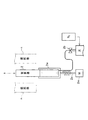
図1に、本発明に係る実施形態1の制御棒操作監視システムが設けられる原子力発電プラントを示す。
実施形態1の原子力発電プラントP(沸騰水型)は、原子炉1、原子炉緊急停止装置4、制御棒操作監視装置3、および制御棒操作監視装置3の運転員操作部7を具備している。
沸騰水型の原子炉1は、ウラニウム等の核分裂の連鎖反応による熱エネルギを用いて高温高圧の蒸気をタービンに供給し発電する仕組みである。
<<
FIG. 1 shows a nuclear power plant provided with a control rod operation monitoring system according to
The nuclear power plant P (boiling water type) according to the first embodiment includes a
The boiling
原子炉緊急停止装置4は、異常状態が検出された場合、原子炉緊急停止信号S3を、原子炉緊急停止系18(図3参照)に出力し、同時に制御棒緊急挿入信号S4を制御棒操作監視装置3に出力する。異常状態とは、原子炉1の出力が制限値を超えて上昇した場合、原子炉1の内部の圧力が制限圧力より上昇した場合、燃料棒2の冷却水の水位が制限水位より低下した場合等である。
When an abnormal condition is detected, the reactor
運転員操作部7は、運転員が原子力発電プラントPの出力を操作するために制御棒2を人為操作により制御、管理する操作部である。運転員操作部7は、制御棒2を燃料棒n間に挿入するに際して、制御棒挿入指令信号S5を制御棒操作監視装置3に出力する。
制御棒操作監視装置3は、原子炉1内の制御棒2の位置を監視し、出力の管理および出力を停止等する装置である。制御棒操作監視装置3は、原子炉1の出力を制御したり、制御棒2を燃料棒n間に挿入したり、緊急挿入したり等する。
The
The control rod
制御棒操作監視装置3は、運転員操作部7からの制御棒挿入指令信号S5により、原子炉1内の下部に配置された制御棒2を燃料棒n間の上方に電動で移動させる。また、制御棒操作監視装置3は、原子炉緊急停止装置4からの制御棒緊急挿入信号S4により、原子炉1内に配置された制御棒2を上方の燃料棒n間に電動で移動させる。
The control rod
図2は、制御棒の電動駆動と水圧駆動との構成を示す概念図である。
制御棒2の電動駆動は以下のように行われる。
制御棒2の下方には電動駆動用の駆動モータ2mが配置されている。駆動モータ2mのモータ軸には制御棒2の下部を支持する支持部材2sが設けられている。駆動モータ2mを稼動し、支持部材2sを前進させることにより、制御棒2を上方に移動させて燃料棒n間に挿入する。一方、駆動モータ2mを稼動し、支持部材2sを後退させることにより、制御棒2を下方に移動させて燃料棒n間から引き抜く。
FIG. 2 is a conceptual diagram showing the configuration of electric drive and hydraulic drive of the control rod.
The electric drive of the
A
制御棒2には不図示の係止部が設けられている。係止部が不図示の被係止部に係止することで、制御棒2は所定の位置に配置し続ける。なお、制御棒2の係止部は、制御棒2が下方に移動する際、被係止部との係止が解除され、制御棒2の下方に引っ込む構成である。
図1に示すように、原子炉緊急停止装置4では、原子炉1内に配置された原子炉出力検出器5からの原子炉出力信号S1や、原子炉水位・圧力検出器6からの原子炉水位・圧力信号S2等を受け、原子炉1の状態を常に監視している。
The
As shown in FIG. 1, in the reactor
原子炉出力検出器5は、原子炉1の出力を検出し、原子炉出力信号S1を原子炉緊急停止装置4に送る。原子炉出力信号S1が示す原子炉出力が制限値以上に大きくなった場合、原子炉緊急停止信号S3による緊急挿入信号が水圧駆動系に送られ、原子炉はスクラムする。また同時に制御棒操作監視装置3に送られる制御棒緊急挿入信号S4により制御棒2を燃料棒n間に上昇させる。
The
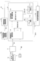
原子炉出力信号S1が示す原子炉出力が異常に上昇した場合や、原子炉水位・圧力信号S2が示す原子炉1の水位が異常に低下した場合、原子炉1の圧力が上昇した場合には、原子炉緊急停止装置4は原子炉1や燃料の健全性を確保するため原子炉緊急停止信号S3を原子炉緊急停止系18(図3参照)に発信する。すると、原子炉緊急停止系18により制御棒2が水圧駆動で短時間で緊急挿入される。図3は、制御棒操作監視システムの構成を示す図である。
When the reactor power indicated by the reactor output signal S1 is abnormally increased, when the water level of the
この時、図1に示すように、原子炉緊急停止装置4は同時に制御棒緊急挿入信号S4を制御棒操作監視装置3に発信し、電動駆動によるバックアップの制御棒2の挿入動作を行う。
At this time, as shown in FIG. 1, the nuclear reactor
原子炉緊急停止系18(図3参照)による制御棒2の水圧駆動は以下のように行われる。
図2に示すように、制御棒2の下方には水槽2wと水槽2wに配管を介して接続される常閉型のスクラムパイロットバルブ2bとが設けられている。スクラムパイロットバルブ2bの上流には、水槽2wに充填するための充填用の水が用意されている。原子炉緊急停止信号S3(図1、3参照)を契機として、スクラムパイロットバルブ2bが開弁され、充填用の水がN2ガスに加圧されて水槽2wに満たされる。充填用の水の圧力により、制御棒2が上方に移動し、燃料棒n間に短時間で挿入される。
なお、制御棒2が水圧駆動で挿入される場合、短時間で行われるので、図6(c)に示す出力密度の上昇という現象は生じない。
制御棒2の水圧駆動は、制御棒2を、水圧により上昇(挿入)させる。
The hydraulic pressure driving of the
As shown in FIG. 2, a
Note that, when the
The water pressure driving of the
<制御棒操作監視装置3>
制御棒操作監視装置3の構成を、図3を用いて説明する。
制御棒操作監視装置3は、全制御棒制御統括部8、個別制御棒制御部9、個別ブレーキ盤10、および個別駆動制御盤11を有している。
全制御棒制御統括部8は、制御棒挿入論理回路を有しており、例えば204本の各燃料棒毎に制御棒2を挿入する指令を個別制御棒制御部9に出力する。
<Control rod
The configuration of the control rod
The control rod
The all control rod
個別制御棒制御部9は、制御棒2毎の個別のタイマ19をもつ個別制御棒挿入論理回路を有する。個別制御棒制御部9は、制御棒2毎の制御部である。個別制御棒制御部9は、制御棒2毎の個別ブレーキ盤10にブレーキ解除指令信号S8を出力する。
個別ブレーキ盤10は、対応する制御棒2のブレーキを、制御棒電動駆動装置12を用いて解除させる。
The individual control rod control unit 9 has an individual control rod insertion logic circuit having an individual timer 19 for each
The
個別駆動制御盤11はインバータ制御部を有する。
個別制御棒制御部9が制御棒緊急挿入指令信号S6または制御棒挿入指令信号S7を個別駆動制御盤11に出力すると、個別駆動制御盤11のインバータ制御部は制御棒電動駆動装置12を用いて、電動駆動による制御棒2の挿入動作を行う。なお、制御棒2のブレーキを解除しないと、制御棒2の挿入動作はできない。つまり、制御棒2の挿入動作は制御棒2のブレーキの解除が前提となる。そのため、制御棒2の電動駆動による挿入操作は、ブレーキの解除、制御棒2の挿入動作の順に行われる。
The individual
When the individual control rod control unit 9 outputs the control rod emergency insertion command signal S6 or the control rod insertion command signal S7 to the individual
制御棒2が燃料棒n(図1参照)間に挿入されるような場合、図3に示すように、全制御棒制御統括部8では原子炉緊急停止装置4からの制御棒緊急挿入信号S4や運転員操作部7からの制御棒挿入指令信号S5が入力される。
すると、全制御棒制御統括部8は、どの制御棒2をどのように挿入するかを、全制御棒制御統括部8内の制御棒挿入論理回路で制御棒2の挿入の対称性等を勘案して判断し、その結果が個別制御棒制御部9に出力される。
When the
Then, all control rod
制御棒2の挿入の対称性とは、原子炉1の内部の複数の燃料棒nに対応する複数の制御棒2を上方から見た場合、複数の制御棒2の中心にほぼ点対称であることを意味する。
The symmetry of insertion of the
個別制御棒制御部9では個別制御棒挿入論理回路で個々の制御棒2を挿入するための個々の制御棒2に対する信号を生成する。
個別制御棒制御部9で生成される信号はブレーキ解除指令信号S8と制御棒緊急挿入指令信号S6と制御棒挿入指令信号S7である。ブレーキ解除指令信号S8は個別ブレーキ盤10に出力され、制御棒緊急挿入指令信号S6および制御棒挿入指令信号S7は個別駆動制御盤11に出力される。
The individual control rod control unit 9 generates signals for the
The signals generated by the individual control rod control unit 9 are a brake release command signal S8, a control rod emergency insertion command signal S6, and a control rod insertion command signal S7. The brake release command signal S8 is output to the
個別ブレーキ盤10はブレーキ解除指令信号S8を受信すると制御棒電動駆動装置12により制御棒2のブレーキ解除を行う。その後、個別駆動制御盤11ではインバータ制御部により制御棒電動駆動装置12が駆動され、電動駆動で制御棒2が燃料棒n間に挿入される。
When receiving the brake release command signal S8, the
制御棒電動駆動装置12の通常運転での制御棒2の挿入動作では、同時に操作できる制御棒2の本数が全205本のうち26本に制限されている。そのため、27本以上および全ての制御棒2の挿入動作が行われた場合には、異常状態と判断される一方、26本以下の制御棒2の挿入動作が行われる場合は正常状態と判断される。
前記したように、従来、制御棒操作監視装置103(図7参照)の障害に対する防御が弱いという問題があった。
そこで、本原子力発電プラントPでは、制御棒操作監視装置3の外部に新たに制御棒挿入動作を制限する機能を有する制御棒操作監視システムS(詳細は下記)を設置する。
In the insertion operation of the
As described above, there has conventionally been a problem that the defense against the failure of the control rod operation monitoring device 103 (see FIG. 7) is weak.
Therefore, in this nuclear power plant P, a control rod operation monitoring system S (details below) having a function of newly restricting the control rod insertion operation is installed outside the control rod
<制御棒操作監視システムS>
制御棒操作監視システムSについて図3に基づき説明する。
制御棒操作監視システムSは、制御棒2が挿入状態に移行する際、制御棒2のブレーキが解除されることから、制御棒2のブレーキ解除状態を検知して、異常状態と判断される場合は、制御棒駆動電源遮断器14により制御棒電動駆動装置12の駆動電源を遮断する。
<Control rod operation monitoring system S>
The control rod operation monitoring system S will be described with reference to FIG.
When the
制御棒操作監視システムSでは、制御棒2の動作状態を判断するため、制御棒2のブレーキの解除状態を電圧電流検出器15で検知する。上述したように、制御棒2を駆動する場合には、まず制御棒2のブレーキが解除される必要がある。そこで、制御棒操作監視システムSでは、制御棒2の挿入動作を検出するため、ブレーキ解除のために制御棒電動駆動装置12に電圧を印加し電流を流す必要があるというメカニズムを利用する。
In the control rod operation monitoring system S, the brake state of the
制御棒操作監視システムSは、前記の制御棒操作監視装置3に加え、電圧電流検出器15と制御棒駆動電源遮断装置13と制御棒駆動電源遮断器14とを有する。
電圧電流検出器15は、制御棒2のブレーキを解除するために、個別ブレーキ盤10から制御棒電動駆動装置12に電圧が印加されたか、または、電流が流れたかを検出する。個別ブレーキ盤10から制御棒電動駆動装置12に電圧が印加されまたは電流が流れたかを検出することで、制御棒2の挿入動作が開始されたかを判定できる。
The control rod operation monitoring system S includes a voltage /
The voltage /
制御棒駆動電源遮断装置13は、制御棒駆動電源遮断論理回路を有しており、制御棒2の異常挿入が発生したか否かを、ブレーキ解除状態信号S10を基に以下のようにして判断する。
前記したように、通常運転での制御棒挿入動作では、同時に操作できる制御棒2の本数が全205本のうち26本に制限されている。
The control rod drive power cut-off
As described above, in the control rod insertion operation in the normal operation, the number of
そこで、制御棒駆動電源遮断装置13は、電圧電流検出器15から入力されるブレーキ解除状態信号S10から、26本を超える制御棒2のブレーキを解除する電圧が印加されまたは電流が流されたかを判断する。同時に操作できる制御棒2の本数が全205本のうち26本であるので、制御棒駆動電源遮断装置13は、27本以上および全ての制御棒2のブレーキが解除された場合は異常状態が発生したと見なす。一方、26本以下の制御棒2のブレーキが解除された場合、正常な状態であると判断する。
Therefore, the control rod drive power cut-off
制御棒駆動電源遮断装置13は、制御棒2の異常挿入(異常状態)が発生したと判断した場合、制御棒駆動電源遮断器14に電源断指令信号S11を出力する。
制御棒駆動電源遮断器14は、制御棒駆動電源遮断装置13からの電源断指令信号S11により制御棒2の挿入動作を担う制御棒電動駆動装置12の駆動電源を遮断する。
When it is determined that the abnormal insertion (abnormal state) of the
The control rod drive power
制御棒操作監視システムSでは、電圧電流検出器15で検知されたブレーキ解除状態信号S10が、制御棒操作監視装置3とは別の独立した制御棒駆動電源遮断装置13に入力される。制御棒駆動電源遮断装置13では、複数の制御棒2が同時に駆動していることをブレーキ解除状態信号S10から検知する。そして、予め定められた本数以上、例えば27本以上および全ての制御棒2が動作した場合、制御棒駆動電源遮断装置13は、電源断指令信号S11を制御棒駆動電源遮断器14に出力する。制御棒駆動電源遮断器14はブレーキが解除される信号が流された制御棒2の制御棒電動駆動装置12の駆動電源を遮断する。この結果、駆動電源を失った制御棒電動駆動装置12は停止し、該当する制御棒2の挿入動作が停止される。
In the control rod operation monitoring system S, the brake release state signal S10 detected by the voltage /
以上の効果から、全制御棒2および制限本数を超える制御棒2が同時に誤挿入とされる場合にその挿入動作を阻止することが可能となる。そのため、全制御棒2の全挿入時および制限本数を超える制御棒2の挿入時に生じる可能性がある燃料棒nの軸方向出力分布の歪(図6参照)を防止することが可能となる。
From the above effects, when all
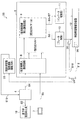
<<実施形態2>>
図4は、実施形態2の制御棒操作監視システムの構成を示す図である。
実施形態2の制御棒操作監視システム2Sでは、制御棒2の動作状態を判断するため、制御棒2の位置信号の変位を制御棒電動駆動装置12に内蔵された制御棒位置検出器16で検知する。これは、制御棒2が駆動される場合には、制御棒2を駆動する駆動モータ2mの回転により制御棒2の位置が鉛直方向に変化する。そこで、制御棒操作監視システム2Sでは、制御棒2の位置の変位を利用して制御棒2の挿入動作を検出する。
<<
FIG. 4 is a diagram illustrating a configuration of a control rod operation monitoring system according to the second embodiment.
In the control rod
制御棒操作監視システム2Sは、前記の制御棒操作監視装置3に加え、制御棒位置検出器16と制御棒駆動電源遮断装置23と制御棒駆動電源遮断器24とを有する。
制御棒位置検出器16は、制御棒2の位置を検出する。制御棒2の位置は、駆動モータ2mの回転位置をロータリーエンコーダにより検出したり、駆動モータ2mのモータ軸に設置される支持部材2sの位置を位置センサで検出したり等して検出される。制御棒2の位置を検出することで、制御棒2の挿入動作が開始されたか否かを判定できる。
The control rod
The control
制御棒駆動電源遮断装置23には、制御棒位置検出器16から制御棒位置信号S12が入力される。制御棒駆動電源遮断装置23はどの制御棒2が挿入状態に移行しようとしているか判定する。前記したように、制御棒駆動電源遮断装置23は、27本以上および全ての制御棒2が挿入状態に移行しようとしている場合は、異常状態と見なす。一方、26本以下の制御棒2が挿入状態に移行しようとしている場合、正常状態と判断する。
制御棒駆動電源遮断器24は、制御棒駆動電源遮断装置23の指令を受けて、挿入状態に移行しようとする制御棒2の制御棒電動駆動装置12の駆動電源を遮断する。
A control rod position signal S12 is input from the control
The control rod drive power
上記構成により、制御棒操作監視システム2Sでは、制御棒位置検出器16で検知された制御棒位置信号S12が、制御棒操作監視装置3とは別の独立した制御棒駆動電源遮断装置23に入力される。制御棒駆動電源遮断装置23では、複数の制御棒2が同時に駆動していることを、制御棒位置信号S12により検知する。
With the above configuration, in the control rod
そして、予め定められた本数以上に制御棒2が動作した場合に電源断指令信号S11を制御棒駆動電源遮断器24に出力する。これにより、制御棒駆動電源遮断器24は、挿入状態に移行しようとしている制御棒2を駆動する制御棒電動駆動装置12の駆動電源を遮断する。駆動電源を失った制御棒電動駆動装置12は停止し、該当する制御棒2の挿入動作は停止する。
Then, when the
以上の効果から、全制御棒2および制限数を超える制御棒2が同時に誤挿入となるような場合にその挿入動作を阻止することが可能となる。
そのため、全制御棒2の全挿入時および制限数を超える制御棒2の挿入時に生じる可能性のある燃料棒の軸方向出力分布の歪(図6(a)〜(c)参照)を抑制することが可能となる。
From the above effects, when all
Therefore, the distortion (refer to FIGS. 6A to 6C) of the axial distribution of fuel rods that may occur when all
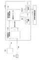
<<実施形態3>>
図5は、実施形態3の制御棒操作監視システムの構成を示す図である。
実施形態3の制御棒操作監視システム3Sは、制御棒2の動作状態を判断するため、前記した制御棒2のブレーキ解除状態(実施形態1)または制御棒位置信号の変位(実施形態2)を利用する。
制御棒操作監視システム3Sは、前記の制御棒操作監視装置3に加え、電圧電流検出器35と制御棒位置検出器36と制御棒駆動電源遮断装置33とを有する。
<<
FIG. 5 is a diagram illustrating a configuration of a control rod operation monitoring system according to the third embodiment.
Since the control rod
The control rod
電圧電流検出器35は、どの制御棒2のブレーキが解除されたかを、個別ブレーキ盤10から制御棒電動駆動装置12に印加される電圧または流れる電流で検出する。
制御棒位置検出器36は、制御棒2の位置を検出する。制御棒2の位置は、前記と同様、駆動モータ2mの回転位置や、駆動モータ2mのモータ軸に設置される支持部材2sの位置を検出する等して検出される。
The voltage /
The control
制御棒駆動電源遮断装置33は、電圧電流検出器35から出力されるブレーキ解除状態信号S10または制御棒位置検出器36から出力される制御棒位置信号S12を受信して、挿入状態に移行する制御棒2を認識する。制御棒駆動電源遮断装置33は、挿入状態に移行する制御棒2の本数が制限数、例えば26本を超える場合および全数の場合には異常状態と判定する一方、挿入状態に移行する制御棒2の本数が制限数以下、例えば26本以下の場合には、正常状態と判定する。
The control rod drive
制御棒操作監視システム3Sにおいて、電圧電流検出器35で検知されたブレーキ解除状態信号S10および制御棒位置信号S12は、制御棒操作監視装置3とは別の独立した制御棒駆動電源遮断装置33に入力される。
In the control rod
制御棒駆動電源遮断装置33では、複数の制御棒2が同時に駆動していることを、ブレーキ解除状態信号S10および/または制御棒位置信号S12を受信して検知する。そして、予め定められた本数以上、例えば27本以上および全ての制御棒2が動作した場合に制御棒駆動電源遮断装置33は異常状態であると判定する。そして、制御棒駆動電源遮断装置33は安全機能である緊急制御棒挿入(スクラム)信号S13を原子炉緊急停止装置4に出力し、原子炉緊急停止装置4から原子炉緊急停止信号S3を原子炉緊急停止系18に出力し、原子炉緊急停止系18によりスクラム(緊急停止)させる。
The control rod drive power shut-off
原子炉緊急停止系18の水圧駆動によるスクラム機能は、電動駆動、ブレーキを稼動する制御棒電動駆動装置12を含む制御棒操作監視装置3とは分離・独立している。よって、原子炉緊急停止系18の水圧駆動によるスクラムでは電動駆動のブレーキの有無に依存せず、スクラム動作する。
The scram function by the hydraulic drive of the nuclear reactor
この結果、制御棒2が緊急挿入される効果から原子炉1は停止し、全制御棒2の全挿入時および制限本数を超える制御棒2の同時挿入時に生じる可能性のある燃料棒2の軸方向出力分布の歪を抑制することが可能となる。
なお、原子炉緊急停止系18の水圧駆動によるスクラム機能では、全制御棒2を短時間で同時に挿入する。よって、制御棒2のグループ分けはしていない。
As a result, the
In the scram function of the reactor
実施形態1〜3の構成によれば、制御棒2の動作状態をブレーキ解除時に印加される電圧または電流により判断し、予め定められた制御棒2の本数以上に制御棒2が動作した場合を検知して制御棒2の駆動電源を遮断する。これにより、制御棒2の誤挿入動作を停止させることが可能となる。
この結果、全制御棒2の全挿入時および制限本数以上の制御棒2の挿入時に生じる可能性のある燃料棒の軸方向出力分布の歪を防止することが可能となる。
According to the configuration of the first to third embodiments, the operation state of the
As a result, it is possible to prevent distortion in the axial output distribution of the fuel rods that may occur when all the
或いは、制御棒2の変位を制御棒電動駆動装置12に内蔵された制御棒位置検出器16により判断し、予め定められた制御棒2の本数以上に制御棒2が動作した場合を検知して制御棒2の駆動電源を遮断する。これにより、制御棒2の誤挿入動作を停止させることが可能となる。この結果、全制御棒2の全挿入時および制限本数以上の制御棒2の挿入時に生じる可能性のある燃料棒の軸方向出力分布の歪を防止することが可能となる。
Alternatively, the displacement of the
さらに、制御棒2のブレーキ解除状態または制御棒位置信号S12で検出される制御棒2の変位から予め定められた制御棒2の本数以上に制御棒2が動作した場合を検知して制御棒緊急挿入(スクラム)信号S4を原子炉緊急停止装置4に入力し、原子炉緊急停止系18によりスクラムさせることが可能となる。この結果、全制御棒2の全挿入時および制限本数以上の制御棒2の挿入時に生じる可能性のある燃料棒の軸方向出力分布の歪を防止することが可能となる。
Further, the
さらに、全制御棒2が全挿入動作する場合および制限本数以上の制御棒2が挿入動作する場合、制御棒操作監視装置3とは別に独立して、制御棒2の動作状態を検知して制御棒2の駆動電源を遮断する機能を実現する。
これにより、制御棒操作監視装置3に障害が発生した場合にも、全制御棒2の挿入動作および制限本数以上の制御棒2の挿入動作を停止させ、燃料の健全性を維持できる。
Further, when all the
Thereby, even when a failure occurs in the control rod
また、制御棒操作監視装置3の別手段として、全制御棒2が全挿入動作する場合および制限本数以上の制御棒2が挿入動作する場合、制御棒操作監視装置3とは別に独立して、制御棒2の動作状態を検知して原子炉緊急停止系18より緊急制御棒挿入動作を行える。
これにより、燃料の健全性を維持できるとともに、原子炉1の安全性を確保できる。
As another means of the control rod
Thereby, while being able to maintain the soundness of a fuel, the safety | security of the
なお、前記実施形態1〜3では、同時に操作できる制御棒2の本数が全205本のうち26本の場合を例示して説明したが、26本以外の本数としてもよい。制御棒2の本数が全205本以外の本数でもよいのは勿論である。
なお、前記実施形態1〜3は、特許請求の範囲に記載した本発明の一例を記載したものであり、特許請求の範囲に記載した本発明の範囲内で様々な具体的形態、変形形態が可能である。
In the first to third embodiments, the number of
The first to third embodiments describe examples of the present invention described in the claims, and various specific forms and modifications can be made within the scope of the present invention described in the claims. Is possible.
1 原子炉
2 制御棒
3 制御棒操作監視装置
4 原子炉緊急停止装置
5 原子炉出力検出器
6 原子炉水位・圧力検出器
8 全制御棒制御統括部(制御棒操作監視装置)
9 個別制御棒制御部(制御棒操作監視装置)
10 個別フ゛レーキ盤(制御棒操作監視装置)
11 個別駆動制御盤(制御棒操作監視装置)
12 制御棒電動駆動装置(電動挿入機能)
13、23 制御棒駆動電源遮断装置(制御棒動作停止装置)
14、24 制御棒駆動電源遮断器(制御棒動作停止装置)
15、35 電圧電流検出器(検出装置)
18 原子炉緊急停止系(緊急制御棒挿入機能)
16、36 制御棒位置検出器(検出装置)
P 原子力発電プラント
S、2S、3S 制御棒操作監視システム
S9 個別タイマ(制御棒操作監視装置)
S10 フ゛レーキ解除状態信号(検出信号)
S12 制御棒位置信号(検出信号)
1
3 Control rod
5
9 Individual control rod control unit (Control rod operation monitoring device)
10 Individual brake board (control rod operation monitoring device)
11 Individual drive control panel (control rod operation monitoring device)
12 Control rod electric drive (electric insertion function)
13, 23 Control rod drive power cut-off device (control rod operation stop device)
14, 24 Control rod drive power circuit breaker (Control rod operation stop device)
15, 35 Voltage / current detector (detection device)
18 Reactor emergency stop system (emergency control rod insertion function)
16, 36 Control rod position detector (detection device)
P Nuclear power plant S, 2S, 3S Control rod operation monitoring system S9 Individual timer (Control rod operation monitoring device)
S10 Brake release status signal (detection signal)
S12 Control rod position signal (detection signal)
Claims (4)
前記各制御棒の挿入開始時間を変更して、前記電動挿入機能により前記制御棒を挿入する制御を行う制御棒操作監視装置と、
前記各制御棒の挿入動作を検出する検出装置と、
前記制御棒操作監視装置とは別装置であって前記検出装置の検出信号により、制限本数以上の前記制御棒の挿入動作を検出した際に前記制御棒の挿入動作を停止する制御棒動作停止装置とを
備えることを特徴とする制御棒操作監視システム。 Emergency control rod insertion function during scram function operation that inserts control rods by hydraulic drive to make the core subcritical at the time of emergency stop of nuclear power plant, and electric operation that inserts all control rods by electric drive of the control rods With an insertion function,
A control rod operation monitoring device for controlling the insertion of the control rod by the electric insertion function by changing the insertion start time of each control rod;
A detection device for detecting an insertion operation of each control rod;
A control rod operation stop device that is separate from the control rod operation monitoring device and that stops the control rod insertion operation when detecting an insertion operation of the control rods exceeding the limit number based on a detection signal of the detection device And a control rod operation monitoring system.
前記各制御棒の挿入開始時間を変更して、前記電動挿入機能により前記制御棒を挿入する制御を行う制御棒操作監視装置と、
前記各制御棒の挿入動作を検出する検出装置と、
前記制御棒操作監視装置とは別装置であって前記検出装置の検出信号により、制限本数以上の前記制御棒の挿入動作を検出した際に原子炉緊急停止装置により前記緊急制御棒挿入機能を行わせる緊急制御棒挿入装置とを
備えることを特徴とする制御棒操作監視システム。 Emergency control rod insertion function during scram function operation that inserts control rods by hydraulic drive to make the core subcritical at the time of emergency stop of nuclear power plant, and electric operation that inserts all control rods by electric drive of the control rods With an insertion function,
A control rod operation monitoring device for controlling the insertion of the control rod by the electric insertion function by changing the insertion start time of each control rod;
A detection device for detecting an insertion operation of each control rod;
The emergency control rod insertion function is performed by a reactor emergency stop device when an insertion operation of the control rod exceeding the limit number is detected by a detection signal of the detection device, which is a separate device from the control rod operation monitoring device. A control rod operation monitoring system comprising an emergency control rod insertion device.
前記検出装置は、前記制御棒のブレーキを解除する制御棒電動駆動装置に、印加される電圧または電流を検出する
ことを特徴とする制御棒操作監視システム。 In the control rod operation monitoring system according to claim 1 or 2,
The control rod operation monitoring system, wherein the detection device detects a voltage or a current applied to a control rod electric drive device that releases a brake of the control rod.
前記検出装置は、前記制御棒の位置を検出する
ことを特徴とする制御棒操作監視システム。 In the control rod operation monitoring system according to claim 1 or 2,
The control rod operation monitoring system, wherein the detection device detects a position of the control rod.
Priority Applications (1)
| Application Number | Priority Date | Filing Date | Title |
|---|---|---|---|
| JP2016079587A JP6606005B2 (en) | 2016-04-12 | 2016-04-12 | Control rod operation monitoring system |
Applications Claiming Priority (1)
| Application Number | Priority Date | Filing Date | Title |
|---|---|---|---|
| JP2016079587A JP6606005B2 (en) | 2016-04-12 | 2016-04-12 | Control rod operation monitoring system |
Publications (2)
| Publication Number | Publication Date |
|---|---|
| JP2017190977A true JP2017190977A (en) | 2017-10-19 |
| JP6606005B2 JP6606005B2 (en) | 2019-11-13 |
Family
ID=60085070
Family Applications (1)
| Application Number | Title | Priority Date | Filing Date |
|---|---|---|---|
| JP2016079587A Active JP6606005B2 (en) | 2016-04-12 | 2016-04-12 | Control rod operation monitoring system |
Country Status (1)
| Country | Link |
|---|---|
| JP (1) | JP6606005B2 (en) |
Cited By (2)
| Publication number | Priority date | Publication date | Assignee | Title |
|---|---|---|---|---|
| JP6381839B1 (en) * | 2018-02-27 | 2018-08-29 | 三菱重工業株式会社 | Reactor shutdown device, reactor shutdown method, and core design method |
| CN113658733A (en) * | 2021-09-07 | 2021-11-16 | 山东核电有限公司 | Control system device of nuclear turbine and control method thereof |
-
2016
- 2016-04-12 JP JP2016079587A patent/JP6606005B2/en active Active
Cited By (4)
| Publication number | Priority date | Publication date | Assignee | Title |
|---|---|---|---|---|
| JP6381839B1 (en) * | 2018-02-27 | 2018-08-29 | 三菱重工業株式会社 | Reactor shutdown device, reactor shutdown method, and core design method |
| JP2019148518A (en) * | 2018-02-27 | 2019-09-05 | 三菱重工業株式会社 | Nuclear reactor shutdown device, nuclear reactor shutdown method and reactor core design method |
| CN113658733A (en) * | 2021-09-07 | 2021-11-16 | 山东核电有限公司 | Control system device of nuclear turbine and control method thereof |
| CN113658733B (en) * | 2021-09-07 | 2024-04-09 | 山东核电有限公司 | Control system device of nuclear turbine and control method thereof |
Also Published As
| Publication number | Publication date |
|---|---|
| JP6606005B2 (en) | 2019-11-13 |
Similar Documents
| Publication | Publication Date | Title |
|---|---|---|
| JP5701033B2 (en) | Reactor shutdown device | |
| JP6606005B2 (en) | Control rod operation monitoring system | |
| JP2018077231A (en) | Methods for protection of nuclear reactors from thermal hydraulic/neutronic core instability | |
| KR101903073B1 (en) | Method and Apparatus for prevention of Reactor Trip in a Loss of one Reactor Coolant Pump | |
| WO2012049935A1 (en) | Control system for nuclear power facility | |
| EP0696032B2 (en) | Transient adjusted overpower protection system | |
| KR930011109B1 (en) | Method of controlling a pwr to prevent overpressure in the event of feed water loss | |
| JP6381839B1 (en) | Reactor shutdown device, reactor shutdown method, and core design method | |
| JP4564203B2 (en) | Reactor control rod malfunction prevention device | |
| JP2020020580A (en) | Nuclear reactor stopping device, nuclear power plant, and method for stopping nuclear reactor | |
| JP6505889B1 (en) | Abnormality alleviation facility for nuclear reactor and method for judging adherence of control rod | |
| US7634043B2 (en) | Protection systems for and methods of operating nuclear boiling water reactors | |
| JP2016145726A (en) | Emergency reactor core cooling system of nuclear power station | |
| JP6823565B2 (en) | Control rod operation monitoring system | |
| WO2018131106A1 (en) | Control rod operation monitoring system and control rod operation monitoring method | |
| WO2018167833A1 (en) | Method for monitoring control rod operation and system for monitoring control rod operation | |
| JP2008008758A (en) | Control rod lifting monitor | |
| KR860000760B1 (en) | The water supply system and method of the p.w.r.reactor | |
| CN115331857A (en) | Control method and device for relieving SGTR accident of pressurized water reactor nuclear power plant and pressurized water reactor of nuclear power plant | |
| JPH0480356B2 (en) | ||
| Kondo et al. | Actual Operation Control of Boiling Water Reactor | |
| JPH05134090A (en) | Full capacity turbine bypass nuclear plant | |
| JPH053557B2 (en) | ||
| Jia et al. | Calculations for AP1000 nuclear power plant SGTR accident based on RELAP5/mod 3.3 program | |
| JPS63285495A (en) | Controlling apparatus of reactor |
Legal Events
| Date | Code | Title | Description |
|---|---|---|---|
| A621 | Written request for application examination |
Free format text: JAPANESE INTERMEDIATE CODE: A621 Effective date: 20180605 |
|
| A977 | Report on retrieval |
Free format text: JAPANESE INTERMEDIATE CODE: A971007 Effective date: 20190313 |
|
| A131 | Notification of reasons for refusal |
Free format text: JAPANESE INTERMEDIATE CODE: A131 Effective date: 20190409 |
|
| A521 | Request for written amendment filed |
Free format text: JAPANESE INTERMEDIATE CODE: A523 Effective date: 20190521 |
|
| TRDD | Decision of grant or rejection written | ||
| A01 | Written decision to grant a patent or to grant a registration (utility model) |
Free format text: JAPANESE INTERMEDIATE CODE: A01 Effective date: 20191001 |
|
| A61 | First payment of annual fees (during grant procedure) |
Free format text: JAPANESE INTERMEDIATE CODE: A61 Effective date: 20191017 |
|
| R150 | Certificate of patent or registration of utility model |
Ref document number: 6606005 Country of ref document: JP Free format text: JAPANESE INTERMEDIATE CODE: R150 |