JP2017190903A - Outdoor unit - Google Patents
Outdoor unit Download PDFInfo
- Publication number
- JP2017190903A JP2017190903A JP2016080110A JP2016080110A JP2017190903A JP 2017190903 A JP2017190903 A JP 2017190903A JP 2016080110 A JP2016080110 A JP 2016080110A JP 2016080110 A JP2016080110 A JP 2016080110A JP 2017190903 A JP2017190903 A JP 2017190903A
- Authority
- JP
- Japan
- Prior art keywords
- refrigerant
- pipe
- compressor
- outdoor unit
- low
- Prior art date
- Legal status (The legal status is an assumption and is not a legal conclusion. Google has not performed a legal analysis and makes no representation as to the accuracy of the status listed.)
- Pending
Links
Images

Abstract
Description
本発明は、室外ユニット、特に、低圧レシーバ、圧縮機、四路切換弁、室外熱交換器及び各機器間を接続する機内冷媒管を有する室外ユニットに関する。 The present invention relates to an outdoor unit, and more particularly to an outdoor unit having a low-pressure receiver, a compressor, a four-way switching valve, an outdoor heat exchanger, and an in-machine refrigerant pipe that connects each device.
従来より、室内ユニットと接続されることによって空気調和装置や冷凍装置の冷媒回路を構成する室外ユニットがある。現在の空気調和装置や冷凍装置の冷媒回路においては、R410Aが冷媒として封入されているものが多いが、最近、地球温暖化防止をさらに促進する観点から、R410Aよりも地球温暖化係数(GWP)が小さいR32が冷媒として封入されるようになってきている。 Conventionally, there is an outdoor unit that constitutes a refrigerant circuit of an air conditioner or a refrigeration apparatus by being connected to an indoor unit. In many refrigerant circuits of current air conditioners and refrigeration apparatuses, R410A is sealed as a refrigerant. Recently, from the viewpoint of further promoting the prevention of global warming, the global warming potential (GWP) is higher than that of R410A. R32 having a small value is being sealed as a refrigerant.
そして、このような冷媒回路に封入される冷媒をR32とした空気調和装置や冷凍装置として、特許文献1(特開2013−200090号公報)には、室内ユニットと室外ユニットとの間を接続する冷媒連絡管の管外径を、冷媒回路にR410Aが封入される場合よりも小さくなるように設定する内容が記載されている。 And as an air-conditioning apparatus or refrigeration apparatus using R32 as the refrigerant sealed in such a refrigerant circuit, Patent Document 1 (Japanese Patent Laid-Open No. 2013-200090) connects an indoor unit and an outdoor unit. The contents of setting the pipe outer diameter of the refrigerant communication pipe to be smaller than when R410A is sealed in the refrigerant circuit are described.
上記従来の構成では、冷媒回路に封入される冷媒(R32)の量や配管材料の使用量を減らすことを目的としているため、冷媒封入量や材料使用量への影響が大きい冷媒連絡管の管外径を小さくするようにしている。 The above-described conventional configuration is intended to reduce the amount of refrigerant (R32) sealed in the refrigerant circuit and the amount of piping material used, so that the refrigerant communication tube having a large influence on the amount of refrigerant enclosed and the amount of material used is large. The outer diameter is made small.
しかし、空気調和装置や冷凍装置では、冷媒封入量や材料使用量の削減だけではなく、近年の省スペース化の動向に伴い、空気調和装置や冷凍装置を構成する室外ユニットに対して、設置スペースの低減が要求されており、特に、定格能力が大きい室外ユニットに対しては、その要求が特に強いものとなっている。ここで、室外ユニットは、低圧レシーバ、圧縮機、四路切換弁、室外熱交換器、及び、各機器間を接続する機内冷媒管を有しており、設置スペースを低減するためには、これらの機器のコンパクト化とともに、機内冷媒管のコンパクト化も必要になる。 However, in the air conditioner and the refrigeration system, not only the amount of refrigerant enclosed and the amount of material used is reduced, but the installation space for the outdoor units constituting the air conditioner and the refrigeration system has been increased due to the recent trend of space saving. In particular, the requirement is particularly strong for an outdoor unit having a large rated capacity. Here, the outdoor unit has a low-pressure receiver, a compressor, a four-way switching valve, an outdoor heat exchanger, and an in-machine refrigerant pipe that connects between each device. In addition to downsizing the equipment, it is also necessary to make the in-machine refrigerant pipe compact.
本発明の課題は、低圧レシーバ、圧縮機、四路切換弁、室外熱交換器及び各機器間を接続する機内冷媒管を有する室外ユニットにおいて、機内冷媒管の管径を小さくし、設置スペースの低減に寄与できるようにすることにある。 An object of the present invention is to reduce the pipe diameter of an in-machine refrigerant pipe in an outdoor unit having an in-machine refrigerant pipe connecting between a low-pressure receiver, a compressor, a four-way switching valve, an outdoor heat exchanger, and each device. It is to be able to contribute to reduction.
第1の観点にかかる室外ユニットは、低圧レシーバ、圧縮機、四路切換弁、室外熱交換器、及び、各機器間を接続する機内冷媒管を有しており、室内ユニットに接続されることによって冷媒回路を構成している。そして、ここでは、冷媒回路に封入される冷媒をR32とし、機内冷媒管のうち、少なくとも、四路切換弁と低圧レシーバとを接続する第1吸入ガス冷媒管、及び、低圧レシーバと圧縮機とを接続する第2吸入ガス冷媒管の管外径を、(Do−1)/8インチ(ここで、「Do/8インチ」は冷媒回路に封入される冷媒をR410Aとした場合の管外径である)としている。 The outdoor unit according to the first aspect has a low-pressure receiver, a compressor, a four-way switching valve, an outdoor heat exchanger, and an in-machine refrigerant pipe that connects each device, and is connected to the indoor unit. Constitutes a refrigerant circuit. And here, the refrigerant sealed in the refrigerant circuit is R32, and among the refrigerant pipes in the machine, at least the first intake gas refrigerant pipe connecting the four-way switching valve and the low-pressure receiver, and the low-pressure receiver and the compressor The outer diameter of the second suction gas refrigerant pipe connecting the pipe is (Do-1) / 8 inch (where "Do / 8 inch" is the pipe outer diameter when the refrigerant enclosed in the refrigerant circuit is R410A). ).
ここでは、冷媒をR32にするとともに、機内冷媒管のうちで管外径が大きくて最も機内スペースを必要とする第1吸入ガス冷媒管及び第2吸入ガス冷媒管の管外径を、冷媒をR410Aにする場合よりも小さくしている。 Here, the refrigerant is R32, and the outer diameters of the first intake gas refrigerant pipe and the second intake gas refrigerant pipe, which have the largest pipe outer diameter among the in-machine refrigerant pipes and require the largest in-machine space, It is smaller than the case of R410A.
これにより、ここでは、機内冷媒管の管径を小さくし、室外ユニットの設置スペースの低減に寄与することができる。 Thereby, here, the pipe diameter of the in-machine refrigerant pipe can be reduced, which can contribute to the reduction of the installation space of the outdoor unit.
第2の観点にかかる室外ユニットは、低圧レシーバ、圧縮機、四路切換弁、室外熱交換器、及び、各機器間を接続する機内冷媒管を有しており、室内ユニットに接続されることによって冷媒回路を構成している。そして、ここでは、冷媒回路に封入される冷媒をR32とし、機内冷媒管のうち、少なくとも、四路切換弁と低圧レシーバとを接続する第1吸入ガス冷媒管、及び、低圧レシーバと圧縮機とを接続する第2吸入ガス冷媒管の管外径を、6/8インチ以下としている。 The outdoor unit according to the second aspect has a low-pressure receiver, a compressor, a four-way switching valve, an outdoor heat exchanger, and an in-machine refrigerant pipe that connects each device, and is connected to the indoor unit. Constitutes a refrigerant circuit. And here, the refrigerant sealed in the refrigerant circuit is R32, and among the refrigerant pipes in the machine, at least the first intake gas refrigerant pipe connecting the four-way switching valve and the low-pressure receiver, and the low-pressure receiver and the compressor The outer diameter of the second intake gas refrigerant pipe connecting the pipes is 6/8 inches or less.
ここでは、冷媒をR32にするとともに、機内冷媒管のうちで管外径が大きくて最も機内スペースを必要とする第1吸入ガス冷媒管及び第2吸入ガス冷媒管の管外径を、6/8インチ以下にしている。ここで、冷媒をR410Aにする場合には、第1吸入ガス冷媒管及び第2吸入ガス冷媒管の管外径の範囲が、冷媒をR32にする場合よりも大きくなる。 Here, the refrigerant is R32, and the pipe outer diameters of the first and second suction gas refrigerant pipes, which have the largest pipe outer diameter and require the most space in the machine, are 6 / 8 inches or less. Here, when the refrigerant is R410A, the outer diameter ranges of the first intake gas refrigerant pipe and the second intake gas refrigerant pipe are larger than when the refrigerant is R32.
これにより、ここでは、機内冷媒管の管径を小さくし、室外ユニットの設置スペースの低減に寄与することができる。 Thereby, here, the pipe diameter of the in-machine refrigerant pipe can be reduced, which can contribute to the reduction of the installation space of the outdoor unit.
第3の観点にかかる室外ユニットは、第1又は第2の観点にかかる室外ユニットにおいて、定格能力を、20.0kWから33.5kWの範囲としている。ここでいう「定格能力」は、室外ユニットの製品カタログや取扱説明書に記載の「呼称能力」と同等の値を意味する。 The outdoor unit according to the third aspect has the rated capacity in the range of 20.0 kW to 33.5 kW in the outdoor unit according to the first or second aspect. The “rated capacity” here means a value equivalent to the “nominal capacity” described in the product catalog or instruction manual of the outdoor unit.
ここでは、上記第1及び第2の観点にかかる機内冷媒管の管外径を、20.0kWから33.5kWという定格能力が大きい室外ユニットに対して採用している。 Here, the pipe outer diameter of the in-machine refrigerant pipe according to the first and second aspects is adopted for an outdoor unit having a large rated capacity of 20.0 kW to 33.5 kW.
これにより、ここでは、定格能力が大きい室外ユニットの設置スペースの低減に寄与にすることができる。 Thereby, it can contribute to reduction of the installation space of an outdoor unit with a large rated capacity here.
第4の観点にかかる室外ユニットは、第1〜第3の観点のいずれかにかかる室外ユニットにおいて、第2吸入ガス冷媒管に、低圧レシーバの出口から圧縮機の入口に至るまでに曲がった管部分である曲管部が複数個形成されている。そして、ここでは、曲管部の個数を、(Nb+1)個以上(ここで、「Nb個」は冷媒回路に封入される冷媒をR410Aとした場合の個数である)としている。ここで、曲管部の個数は、低圧レシーバの容器本体部分を出た直後から圧縮機のケーシング部分(付属レシーバを有する圧縮機の場合には、付属レシーバの容器本体部分)に入るまでの間の曲管部の個数である。 The outdoor unit according to the fourth aspect is a tube bent from the outlet of the low-pressure receiver to the inlet of the compressor in the second intake gas refrigerant pipe in the outdoor unit according to any of the first to third aspects. A plurality of curved pipe portions, which are portions, are formed. Here, the number of the bent pipe portions is (Nb + 1) or more (here, “Nb” is the number when the refrigerant enclosed in the refrigerant circuit is R410A). Here, the number of bent pipes is from immediately after leaving the container body part of the low-pressure receiver until it enters the casing part of the compressor (in the case of a compressor having an attached receiver, the container body part of the attached receiver). This is the number of curved pipe parts.
機内冷媒管のうち第2吸入ガス冷媒管は、機内冷媒管のうちで最も管外径が大きいにもかかわらず、圧縮機に直接接続されているため、室外ユニットの輸送時の振動や圧縮機の運転時の振動の影響を最も受けやすい。このため、第2吸入ガス冷媒管には、輸送振動や運転振動の影響を緩和するために、低圧レシーバの出口から圧縮機の入口に至るまでに曲がった管部分である曲管部を複数個形成する必要がある。 The second suction gas refrigerant pipe among the in-machine refrigerant pipes is directly connected to the compressor even though the pipe outer diameter is the largest among the in-machine refrigerant pipes. Most susceptible to vibration during driving. For this reason, the second suction gas refrigerant pipe has a plurality of bent pipe portions that are bent from the outlet of the low-pressure receiver to the inlet of the compressor in order to alleviate the influence of transportation vibration and operation vibration. Need to form.
しかし、冷媒をR410Aにする場合には、第2吸入ガス冷媒管の管外径が大きいことから、設置スペースを大きくせずに、曲管部の個数を多くすることが難しい。 However, when the refrigerant is R410A, it is difficult to increase the number of bent pipe parts without increasing the installation space because the outer diameter of the second suction gas refrigerant pipe is large.
そこで、ここでは、上記のように、冷媒をR32にするとともに、第2吸入ガス冷媒管の管外径を、冷媒をR410Aにする場合よりも小さくしていることを利用して、第2吸入ガス冷媒管の曲管部の個数を、冷媒をR410Aにする場合よりも1個以上多くしている。 Therefore, here, as described above, the second suction is performed by using the fact that the refrigerant is R32 and the outer diameter of the second suction gas refrigerant pipe is smaller than that when the refrigerant is R410A. The number of curved pipe portions of the gas refrigerant pipe is one or more than that when the refrigerant is R410A.
これにより、ここでは、設置スペースが大きくなることを抑えつつ、第2吸入ガス冷媒管の曲管部の個数を多くすることが可能になり、第2吸入ガス冷媒管に対する輸送振動や運転振動の影響を緩和することができる。 This makes it possible to increase the number of bent portions of the second intake gas refrigerant tube while suppressing an increase in installation space, and to reduce transportation vibration and operation vibration with respect to the second intake gas refrigerant tube. The impact can be mitigated.
第5の観点にかかる室外ユニットは、第1〜第3の観点のいずれかにかかる室外ユニットにおいて、第2吸入ガス冷媒管が、低圧レシーバの出口から圧縮機の入口に至るまでに鉛直方向に延びる直管部分である鉛直管部が複数本形成されるように曲げられた形状を有している。そして、ここでは、鉛直管部の管本数を、(Np+1)本以上(ここで、「Np本」は冷媒回路に封入される冷媒をR410Aとした場合の管本数である)としている。ここで、鉛直管部の管本数は、低圧レシーバの容器本体部分を出た直後から圧縮機のケーシング部分(付属レシーバを有する圧縮機の場合には、付属レシーバの容器本体部分)に入るまでの間の鉛直管部の管本数である。 The outdoor unit according to the fifth aspect is the outdoor unit according to any one of the first to third aspects, wherein the second intake gas refrigerant pipe extends vertically from the outlet of the low-pressure receiver to the inlet of the compressor. It has a bent shape so that a plurality of vertical pipe portions, which are straight pipe portions extending, are formed. Here, the number of tubes in the vertical tube portion is set to (Np + 1) or more (here, “Np” is the number of tubes when the refrigerant enclosed in the refrigerant circuit is R410A). Here, the number of pipes in the vertical pipe section is from immediately after leaving the container main body portion of the low-pressure receiver until it enters the casing portion of the compressor (in the case of a compressor having an attached receiver, the container body portion of the attached receiver). It is the number of pipes in the vertical pipe.
機内冷媒管のうち第2吸入ガス冷媒管は、機内冷媒管のうちで最も管外径が大きいにもかかわらず、圧縮機に直接接続されているため、室外ユニットの輸送時の振動や圧縮機の運転時の振動の影響を最も受けやすい。このため、第2吸入ガス冷媒管は、輸送振動や運転振動の影響を緩和するために、低圧レシーバの出口から圧縮機の入口に至るまでに鉛直管部が複数本形成されるように曲げられた形状にする必要がある。 The second suction gas refrigerant pipe among the in-machine refrigerant pipes is directly connected to the compressor even though the pipe outer diameter is the largest among the in-machine refrigerant pipes. Most susceptible to vibration during driving. For this reason, the second intake gas refrigerant pipe is bent so that a plurality of vertical pipe portions are formed from the outlet of the low-pressure receiver to the inlet of the compressor in order to reduce the influence of transportation vibration and operation vibration. It is necessary to have a different shape.
しかし、冷媒をR410Aにする場合には、第2吸入ガス冷媒管の管外径が大きいことから、設置スペースを大きくせずに、鉛直管部の管本数を多くすることが難しい。 However, when the refrigerant is R410A, it is difficult to increase the number of pipes in the vertical pipe portion without increasing the installation space because the outer diameter of the second suction gas refrigerant pipe is large.
そこで、ここでは、上記のように、冷媒をR32にするとともに、第2吸入ガス冷媒管の管外径を、冷媒をR410Aにする場合よりも小さくしていることを利用して、第2吸入ガス冷媒管の鉛直管部の管本数を、冷媒をR410Aにする場合よりも1本以上多くしている。 Therefore, here, as described above, the second suction is performed by using the fact that the refrigerant is R32 and the outer diameter of the second suction gas refrigerant pipe is smaller than that when the refrigerant is R410A. The number of the vertical pipe portions of the gas refrigerant pipe is one or more than that when the refrigerant is R410A.
これにより、ここでは、設置スペースが大きくなることを抑えつつ、第2吸入ガス冷媒管の鉛直管部の管本数を多くすることが可能になり、第2吸入ガス冷媒管に対する輸送振動や運転振動の影響を緩和することができる。 Thereby, here, it becomes possible to increase the number of pipes of the vertical pipe portion of the second intake gas refrigerant tube while suppressing an increase in installation space, and transportation vibration and operation vibration with respect to the second intake gas refrigerant tube. Can alleviate the effects.
第6の観点にかかる室外ユニットは、第1〜第3の観点のいずれかにかかる室外ユニットにおいて、第2吸入ガス冷媒管に、低圧レシーバの出口から圧縮機の入口に至るまでに曲がった管部分である曲管部が複数個形成されている。そして、ここでは、曲管部の個数を、4個から10個の範囲としている。ここで、曲管部の個数は、低圧レシーバの容器本体部分を出た直後から圧縮機のケーシング部分(付属レシーバを有する圧縮機の場合には、付属レシーバの容器本体部分)に入るまでの間の曲管部の個数である。 The outdoor unit according to the sixth aspect is a tube bent from the outlet of the low-pressure receiver to the inlet of the compressor in the second intake gas refrigerant pipe in the outdoor unit according to any of the first to third aspects. A plurality of curved pipe portions, which are portions, are formed. In this case, the number of bent pipe portions is in the range of 4 to 10. Here, the number of bent pipes is from immediately after leaving the container body part of the low-pressure receiver until it enters the casing part of the compressor (in the case of a compressor having an attached receiver, the container body part of the attached receiver). This is the number of curved pipe parts.
機内冷媒管のうち第2吸入ガス冷媒管は、機内冷媒管のうちで最も管外径が大きいにもかかわらず、圧縮機に直接接続されているため、室外ユニットの輸送時の振動や圧縮機の運転時の振動の影響を最も受けやすい。このため、第2吸入ガス冷媒管には、輸送振動や運転振動の影響を緩和するために、低圧レシーバの出口から圧縮機の入口に至るまでに曲がった管部分である曲管部を複数個形成する必要がある。 The second suction gas refrigerant pipe among the in-machine refrigerant pipes is directly connected to the compressor even though the pipe outer diameter is the largest among the in-machine refrigerant pipes. Most susceptible to vibration during driving. For this reason, the second suction gas refrigerant pipe has a plurality of bent pipe portions that are bent from the outlet of the low-pressure receiver to the inlet of the compressor in order to alleviate the influence of transportation vibration and operation vibration. Need to form.
しかし、冷媒をR410Aにする場合には、第2吸入ガス冷媒管の管外径が大きいことから、設置スペースを大きくせずに、曲管部の個数を多くすることが難しい。 However, when the refrigerant is R410A, it is difficult to increase the number of bent pipe parts without increasing the installation space because the outer diameter of the second suction gas refrigerant pipe is large.
そこで、ここでは、上記のように、冷媒をR32にするとともに、第2吸入ガス冷媒管の管外径を、冷媒をR410Aにする場合よりも小さくしていることを利用して、第2吸入ガス冷媒管の曲管部の個数を、4個から10個の範囲としている。ここで、冷媒をR410Aにする場合には、第2吸入ガス冷媒管の曲管部の個数の範囲が、冷媒をR32にする場合よりも1個以上少なくなる。 Therefore, here, as described above, the second suction is performed by using the fact that the refrigerant is R32 and the outer diameter of the second suction gas refrigerant pipe is smaller than that when the refrigerant is R410A. The number of curved pipe portions of the gas refrigerant pipe is in the range of 4 to 10. Here, when the refrigerant is R410A, the range of the number of bent pipe portions of the second intake gas refrigerant pipe is one or more less than that when the refrigerant is R32.
これにより、ここでは、設置スペースが大きくなることを抑えつつ、第2吸入ガス冷媒管の曲管部の個数を多くすることが可能になり、第2吸入ガス冷媒管に対する輸送振動や運転振動の影響を緩和することができる。 This makes it possible to increase the number of bent portions of the second intake gas refrigerant tube while suppressing an increase in installation space, and to reduce transportation vibration and operation vibration with respect to the second intake gas refrigerant tube. The impact can be mitigated.
第7の観点にかかる室外ユニットは、第1〜第3の観点のいずれかにかかる室外ユニットにおいて、第2吸入ガス冷媒管が、低圧レシーバの出口から圧縮機の入口に至るまでに鉛直方向に延びる直管部分である鉛直管部が複数本形成されるように曲げられた形状を有している。そして、ここでは、鉛直管部の管本数を、3本から6本の範囲としている。ここで、鉛直管部の管本数は、低圧レシーバの容器本体部分を出た直後から圧縮機のケーシング部分(付属レシーバを有する圧縮機の場合には、付属レシーバの容器本体部分)に入るまでの間の鉛直管部の管本数である。 An outdoor unit according to a seventh aspect is the outdoor unit according to any one of the first to third aspects, wherein the second suction gas refrigerant pipe extends vertically from the outlet of the low-pressure receiver to the inlet of the compressor. It has a bent shape so that a plurality of vertical pipe portions, which are straight pipe portions extending, are formed. And here, the number of pipes in the vertical pipe section is in the range of 3 to 6. Here, the number of pipes in the vertical pipe section is from immediately after leaving the container main body portion of the low-pressure receiver until it enters the casing portion of the compressor (in the case of a compressor having an attached receiver, the container body portion of the attached receiver). It is the number of pipes in the vertical pipe.
機内冷媒管のうち第2吸入ガス冷媒管は、機内冷媒管のうちで最も管外径が大きいにもかかわらず、圧縮機に直接接続されているため、室外ユニットの輸送時の振動や圧縮機の運転時の振動の影響を最も受けやすい。このため、第2吸入ガス冷媒管は、輸送振動や運転振動の影響を緩和するために、低圧レシーバの出口から圧縮機の入口に至るまでに鉛直管部が複数本形成されるように曲げられた形状にする必要がある。 The second suction gas refrigerant pipe among the in-machine refrigerant pipes is directly connected to the compressor even though the pipe outer diameter is the largest among the in-machine refrigerant pipes. Most susceptible to vibration during driving. For this reason, the second intake gas refrigerant pipe is bent so that a plurality of vertical pipe portions are formed from the outlet of the low-pressure receiver to the inlet of the compressor in order to reduce the influence of transportation vibration and operation vibration. It is necessary to have a different shape.
しかし、冷媒をR410Aにする場合には、第2吸入ガス冷媒管の管外径が大きいことから、設置スペースを大きくせずに、鉛直管部の管本数を多くすることが難しい。 However, when the refrigerant is R410A, it is difficult to increase the number of pipes in the vertical pipe portion without increasing the installation space because the outer diameter of the second suction gas refrigerant pipe is large.
そこで、ここでは、上記のように、冷媒をR32にするとともに、第2吸入ガス冷媒管の管外径を、冷媒をR410Aにする場合よりも小さくしていることを利用して、第2吸入ガス冷媒管の鉛直管部の管本数を、3本から6本の範囲としている。ここで、冷媒をR410Aにする場合には、第2吸入ガス冷媒管の鉛直管部の管本数の範囲が、冷媒をR32にする場合よりも1本以上少なくなる。 Therefore, here, as described above, the second suction is performed by using the fact that the refrigerant is R32 and the outer diameter of the second suction gas refrigerant pipe is smaller than that when the refrigerant is R410A. The number of pipes in the vertical pipe portion of the gas refrigerant pipe is in the range of 3 to 6. Here, when the refrigerant is R410A, the range of the number of the vertical pipe portions of the second intake gas refrigerant pipe is one or more less than that when the refrigerant is R32.
これにより、ここでは、設置スペースが大きくなることを抑えつつ、第2吸入ガス冷媒管の鉛直管部の管本数を多くすることが可能になり、第2吸入ガス冷媒管に対する輸送振動や運転振動の影響を緩和することができる。 Thereby, here, it becomes possible to increase the number of pipes of the vertical pipe portion of the second intake gas refrigerant tube while suppressing an increase in installation space, and transportation vibration and operation vibration with respect to the second intake gas refrigerant tube. Can alleviate the effects.
以上の説明に述べたように、本発明によれば、低圧レシーバ、圧縮機、四路切換弁、室外熱交換器及び各機器間を接続する機内冷媒管を有する室外ユニットにおいて、機内冷媒管の管径を小さくし、室外ユニットの設置スペースの低減に寄与することができる。 As described in the above description, according to the present invention, in the outdoor unit having the low-pressure receiver, the compressor, the four-way switching valve, the outdoor heat exchanger, and the in-machine refrigerant pipe connecting each device, It is possible to reduce the tube diameter and contribute to the reduction of the installation space of the outdoor unit.
以下、本発明にかかる室外ユニットの実施形態及びその変形例について、図面に基づいて説明する。尚、本発明にかかる室外ユニットの具体的な構成は、下記の実施形態及びその変形例に限られるものではなく、発明の要旨を逸脱しない範囲で変更可能である。 DESCRIPTION OF EMBODIMENTS Hereinafter, embodiments of an outdoor unit according to the present invention and modifications thereof will be described with reference to the drawings. Note that the specific configuration of the outdoor unit according to the present invention is not limited to the following embodiments and modifications thereof, and can be changed without departing from the scope of the invention.
(1)空気調和装置の構成
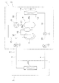
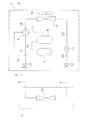
図1は、本発明の一実施形態にかかる室外ユニット2を有する空気調和装置1の概略構成図である。
(1) Configuration of Air Conditioner FIG. 1 is a schematic configuration diagram of an air conditioner 1 having an
空気調和装置1は、蒸気圧縮式の冷凍サイクルを行うことによって、建物等の室内の冷房や暖房を行うことが可能な装置である。空気調和装置1は、主として、室外ユニット2と、室内ユニット3とが接続されることによって構成されている。ここで、室外ユニット2と室内ユニット3とは、液冷媒連絡管4及びガス冷媒連絡管5を介して接続されている。すなわち、空気調和装置1の蒸気圧縮式の冷媒回路6は、室外ユニット2と、室内ユニット3とが冷媒連絡管4、5を介して接続されることによって構成されている。
The air conditioner 1 is a device capable of cooling and heating a room such as a building by performing a vapor compression refrigeration cycle. The air conditioner 1 is mainly configured by connecting an
室外ユニット2は、室外に設置されており、冷媒回路6の一部を構成している。室外ユニット2は、主として、低圧レシーバ7と、圧縮機8と、四路切換弁9と、室外熱交換器10と、膨張弁11と、液側閉鎖弁12と、ガス側閉鎖弁13と、室外ファン14と、を有している。各機器及び弁間は、機内冷媒管15〜21によって接続されている。
The
室内ユニット3は、室内に設置されており、冷媒回路6の一部を構成している。室内ユニット3は、主として、室内熱交換器22を有している。
The
冷媒連絡管4、5は、空気調和装置1を建物等の設置場所に設置する際に、現地にて施工される冷媒管である。液冷媒連絡管4の一端は、室外ユニット2の液側閉鎖弁12に接続され、液冷媒連絡管4の他端は、室内ユニット3の室内熱交換器21の液側端に接続されている。ガス冷媒連絡管5の一端は、室外ユニット2のガス側閉鎖弁13に接続され、ガス冷媒連絡管5の他端は、室内ユニット3の室内熱交換器22のガス側端に接続されている。
The
このような冷媒回路6を有する空気調和装置1は、冷房時において、主として、低圧レシーバ7、圧縮機8、四路切換弁9、放熱器としての室外熱交換器10、膨張弁11、蒸発器としての室内熱交換器22、四路切換弁9、低圧レシーバ7の順に冷媒を循環させる冷凍サイクルを行うようになっている。また、空気調和装置1は、暖房時において、主として、低圧レシーバ7、圧縮機8、四路切換弁9、放熱器としての室内熱交換器22、膨張弁11、蒸発器としての室外熱交換器10、四路切換弁9、低圧レシーバ7の順に冷媒を循環させる冷凍サイクルを行うようになっている。
The air conditioner 1 having such a
(2)室外ユニットの構成
<全体>
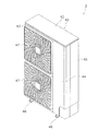
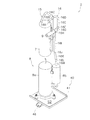
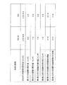
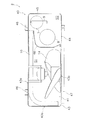
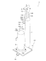
図2は、室外ユニット2の外観斜視図である。図3は、室外ユニット2の平面図(天板42と、低圧レシーバ7、圧縮機8、四路切換弁9及び室外熱交換器10以外の冷媒回路構成部品と、を取り除いて図示)である。図4は、冷媒回路6に封入される冷媒をR32とした場合における低圧レシーバ7、圧縮機8、四路切換弁9及び吸入ガス冷媒管15、16の配置を示す概略斜視図である。図5は、冷媒回路6に封入される冷媒をR410Aとした場合とR32とした場合における、機内冷媒管15〜18、21の管外径と、第2吸入ガス冷媒管16の曲管部の個数と、第2吸入ガス冷媒管16の鉛直管部の管本数と、を示す図である。
(2) Configuration of outdoor unit <Overall>
FIG. 2 is an external perspective view of the
室外ユニット2は、略直方体箱状のケーシング40の内部が鉛直に延びる仕切板48により送風機室S1と機械室S2とに分割されたトランク型の構造と呼ばれるものである。室外ユニット2は、主として、略直方体箱状のケーシング40と、室外ファン14と、低圧レシーバ7や圧縮機8等の機器、膨張弁11や閉鎖弁12、13等の弁及び冷媒管15〜21等を含み冷媒回路6の一部を構成する冷媒回路構成部品と、を有している。尚、以下の説明において、「上」、「下」、「左」、「右」、「前」、「後」、「前面」、「背面」は、特にことわりのない限り、図2に示される室外ユニット2を前方(図面の左斜前側)から見た場合の方向を意味している。
The
<ケーシング>
ケーシング40は、主として、底フレーム41と、天板42と、左前板43と、右前板44と、右側板45と、を有している。
<Casing>
The
底フレーム41は、ケーシング40の底面部分を構成する横長の略長方形状の板状部材である。底フレーム41の下面には、現地設置面に固定される2つの固定脚46が設けられている。
The
天板42は、ケーシング40の天面部分を構成する横長の略長方形状の板状部材である。
The
左前板43は、主として、ケーシング40の左前面部分及び左側面部分を構成する板状部材であり、その下部が底フレーム41にネジ等により固定されている。左前板43には、室外ファン14によってケーシング40内に吸入される空気の吸入口43aが形成されている。また、左前板43には、室外ファン14によってケーシング40の背面側及び左側面側から内部に取り込まれた空気を外部に吹き出すための吹出口43bが設けられている。吹出口43bは、ここでは、上下2つ形成されており、それぞれにファングリル47が設けられている。
The left
右前板44は、主として、ケーシング40の右前面部分及び右側面の前部を構成する板状部材であり、その下部が底フレーム41にネジ等により固定されている。また、右前板44は、その左端部が左前板43の右端部にネジ等により固定されている。
The right
右側板45は、主として、ケーシング40の右側面の後部及び右背面部分を構成する板状部材であり、その下部が底フレーム41にネジ等により固定されている。そして、左前板43の後端部と右側板45の背面側端部と左右方向間には、室外ファン14によってケーシング40内に吸入される空気の吸入口43cが形成されている。
The
また、ケーシング40内には、仕切板48が設けられている。仕切板48は、底フレーム41上に配置される鉛直に延びる板状部材であり、ケーシング40の内部を左右2つの空間に仕切るように配置されている。仕切板48は、ケーシング40を上方から見た際に、左前板43の右端部から背面側に向かって延びている。左前板43の右端部は、仕切板48の前端部にネジ等により固定されている。
A
このように、ケーシング40は、その内部が仕切板48により送風機室S1と機械室S2とに分割されている。より具体的には、送風機室S1は、底フレーム41と、天板42と、左前板43と、仕切板48とによって囲まれた空間であり、主として、室外ファン14や室外熱交換器10が配置されている。機械室S2は、底フレーム41と、天板42と、右前板44と、右側板45と、仕切板48とによって囲まれた空間であり、主として、室外熱交換器10以外の冷媒回路構成部品が配置されている。
As described above, the
<室外ファン>
室外ファン14は、送風機室S1内の室外熱交換器10の前側に設けられている。ここでは、室外ファン14は、プロペラファンであり、吹出口43bに対向するように、送風機室S1内に上下2つ配置されている。
<Outdoor fans>
The
<冷媒回路構成部品>
低圧レシーバ7は、圧縮機8に吸入される冷媒を一時的に溜めるための大型の略円筒形状の容器であり、機械室S2内の圧縮機8の上側に設けられている。低圧レシーバ7の入口は、第1吸入ガス冷媒連絡管15を介して四路切換弁9に接続されており、低圧レシーバ7の出口は、第2吸入ガス冷媒連絡管16を介して圧縮機8に接続されている。ここで、低圧レシーバ7は、「アキュムレータ」とも呼ばれることがある。
<Refrigerant circuit components>
The low-
圧縮機8は、冷媒を圧縮するための機器であり、機械室S2内に設けられている。ここでは、圧縮機8は、圧縮機本体8a及び付属レシーバ8bによって構成される付属レシーバ付きの圧縮機である。圧縮機本体8aは、略円筒形状のハウジング内に冷媒を圧縮するための圧縮機構及び圧縮機構を回転駆動するためのモータが収容された密閉式圧縮機である。付属レシーバ8bは、圧縮機本体8aに吸入される冷媒を一時的に溜めるために圧縮機本体8aの側部に設けられるとともに配管接続された小型の略円筒形状の容器である。圧縮機8の吸入口としての付属レシーバ8bの入口は、機内冷媒管の1つである第2吸入ガス冷媒管16を介して低圧レシーバ7の出口に接続されており、圧縮機8の吐出口としての圧縮機本体8aの出口は、機内冷媒管の1つである吐出ガス冷媒管17(図1参照)を介して四路切換弁9に接続されている。
The
四路切換弁9は、冷媒回路6(図1参照)における冷媒の循環方向を切り換えるための切換弁であり、機械室S2内の低圧レシーバ7の横側に設けられている。四路切換弁9は、4つのポートを有しており、その第1のポートは、機内冷媒管の1つである第2ガス冷媒連絡管21(図1参照)を介してガス側閉鎖弁13(図1参照)に接続されている。四路切換弁9の第2のポートは、第1吸入ガス冷媒連絡管15を介して低圧レシーバ7の入口に接続されており、第3ポートは、吐出ガス冷媒連絡管17を介して圧縮機8の吐出口に接続されており、第4ポートは、第1ガス冷媒連絡管18(図1参照)を介して室外熱交換器10に接続されている。
The four-
機械室S2内には、他の冷媒回路構成部品11〜13、19、20も設けられているが、ここでは説明を省略する。
Other
室外熱交換器10は、送風機室S1内に設けられており、室外ファン14によってケーシング40内に取り込まれた空気との間で熱交換を行う熱交換器である。ここでは、室外熱交換器10は、ケーシング40の左側面から背面に沿うように配置された略L字形状をなしている。
The
−機内冷媒管の管外径−
上記のような構成を有する室外ユニット2においては、設置スペースの低減が要求されており、特に、定格能力が大きなものに対しては、その要求が特に強いものとなっている。ここで、室外ユニット2の設置スペースを低減するためには、圧縮機8や室外熱交換器10のような機器のコンパクト化とともに、機内冷媒管15〜21のコンパクト化も必要である。
-Outer diameter of refrigerant pipe in machine-
In the
そこで、ここでは、冷媒回路6に封入される冷媒をR32とし、機内冷媒管15〜21のうち、少なくとも、第1吸入ガス冷媒管15、及び、第2吸入ガス冷媒管16の管外径を、冷媒回路6に封入される冷媒をR410Aとした同一の定格能力の室外ユニット2よりも小さくしている。すなわち、ここでは、冷媒回路6に封入される冷媒をR32にするとともに、機内冷媒管15〜21のうちで管外径が大きくて最も機内スペースを必要とする第1吸入ガス冷媒管15及び第2吸入ガス冷媒管16の管外径を、冷媒をR410Aにする場合よりも小さくしている。
Therefore, here, the refrigerant sealed in the
ここで、機内冷媒管15〜21の管外径は、冷媒回路6において所定の定格能力を得るために必要な冷媒の冷媒循環量、及び、機内冷媒管15〜21で許容できる圧力損失を算出しておき、機内冷媒管15〜21における圧力損失が許容範囲に収まるように設定することによって行われる。尚、ここでは、室外ユニット2の定格能力の範囲を、20.0kW(8馬力)から33.5kW(12馬力)とし、トランク型の室外ユニットの中では大型のものを対象としている。また、ここでいう「定格能力」は、室外ユニット2の製品カタログや取扱説明書に記載の「呼称能力」と同等の値を意味する。
Here, the pipe outer diameters of the in-
そうすると、冷媒をR410Aとした場合に比べて冷媒をR32とした場合のほうが、同一の定格能力において冷媒循環量を減らすことができるため、冷媒をR32とする場合に、機内冷媒管15〜21の管外径を、冷媒をR410Aにする場合よりも小さくしている。図5においては、第1吸入ガス冷媒管15及び第2吸入ガス冷媒管16を含むガス冷媒が流れる機内冷媒管15〜18、21の管外径が記載されているが、いずれの機内冷媒管15〜18、21についても、冷媒をR32とした場合に、冷媒をR410Aとした場合よりも管外径を小さくしている。そして、ここでは、冷媒回路6に封入される冷媒をR410Aとした場合の機内冷媒管15〜21の管外径を「Do/8インチ」として、冷媒回路6に封入される冷媒をR32とした場合の機内冷媒管15〜18、21の管外径を、(Do−1)/8インチにしている。すなわち、冷媒回路6に封入される冷媒をR32とした場合の機内冷媒管15〜21の管外径を、冷媒回路6に封入される冷媒をR410Aとした場合の機内冷媒管15〜21の管外径よりも1サイズ小さくしている。
Then, compared to the case where the refrigerant is R410A, when the refrigerant is R32, the refrigerant circulation amount can be reduced at the same rated capacity. Therefore, when the refrigerant is R32, The pipe outer diameter is made smaller than that when the refrigerant is R410A. In FIG. 5, the outer diameters of the in-
具体的には、冷媒回路6に封入される冷媒をR32とした場合に、機内冷媒管15〜21の管外径を6/8インチ以下にしている。ここでは、冷媒回路6に封入される冷媒をR32とした場合に、吐出ガス冷媒管17の管外径を4/8〜5/8インチ(冷媒をR410Aとした場合は5/8〜6/8インチ)にし、第1ガス冷媒管18の管外径を5/8インチ(冷媒をR410Aとした場合は6/8インチ)にし、第2ガス冷媒管21の管外径を6/8インチ(冷媒をR410Aとした場合は7/8インチ)にしている。そして、機内冷媒管15〜21のうちで管外径が大きくて最も機内スペースを必要とする第1吸入ガス冷媒管15及び第2吸入ガス冷媒管16の管外径を6/8インチ(冷媒をR410Aとした場合は7/8インチ)にしている。言い換えれば、冷媒をR410Aにする場合には、機内冷媒管15〜21の管外径の範囲が、冷媒をR32にする場合よりも大きくなるということである。
Specifically, when the refrigerant sealed in the
これにより、ここでは、機内冷媒管15〜21の管径を小さくし、室外ユニット2の設置スペースの低減に寄与することができる。特に、ここでは、上記の機内冷媒管15〜21の管外径を、20.0kWから33.5kWという定格能力が大きい室外ユニット2に対して採用しているため、室外ユニット2の設置スペースの低減への寄与が顕著である。
Thereby, here, the pipe diameter of the in-
−第2吸入ガス冷媒管の曲がり形状−
機内冷媒管15〜21のうち第2吸入ガス冷媒管16は、機内冷媒管15〜21のうちで最も管外径が大きいにもかかわらず、圧縮機8に直接接続されているため、室外ユニット2の輸送時の振動や圧縮機8の運転時の振動の影響を最も受けやすい。このため、第2吸入ガス冷媒管16には、輸送振動や運転振動の影響を緩和するために、低圧レシーバ7の出口から圧縮機8の入口に至るまでに曲がった管部分である曲管部(曲がった管部分)を複数個形成する、又は、低圧レシーバ7の出口から圧縮機8の入口に至るまでに鉛直管部(鉛直方向に延びる直管部分)が複数本形成されるように曲げられた形状にする必要がある。ここで、曲管部の個数は、低圧レシーバ7の容器本体部分を出た直後から圧縮機8を構成する付属レシーバ8bの容器本体部分に入るまでの間の曲管部の個数である。また、鉛直管部の管本数は、低圧レシーバ7の容器本体部分を出た直後から圧縮機8のケーシング部分(ここでは、付属レシーバ8bを有する圧縮機8であるため、付属レシーバ8bの容器本体部分)に入るまでの間の鉛直管部の管本数である。
-Bent shape of second suction gas refrigerant pipe-
The second intake
しかし、冷媒をR410Aにする場合には、第2吸入ガス冷媒管16の管外径が大きいことから、設置スペースを大きくせずに、曲管部の個数や鉛直管部の管本数を多くすることが難しい。
However, when the refrigerant is R410A, since the outer diameter of the second intake
そこで、ここでは、上記のように、冷媒をR32にするとともに、第2吸入ガス冷媒管16の管外径を、冷媒をR410Aにする場合よりも小さくしていることを利用して、第2吸入ガス冷媒管16の曲管部の個数を、冷媒をR410Aにする場合よりも1個以上多くする、又は、第2吸入ガス冷媒管16の鉛直管部の管本数を、冷媒をR410Aにする場合よりも1本以上多くしている。
Therefore, here, as described above, the refrigerant is made R32 and the second suction
ここで、第2吸入ガス冷媒管16の曲がり形状は、室外ユニット2(ここでは、機械室S2)内の所定の位置に低圧レシーバ7及び圧縮機8を設け、第2吸入ガス冷媒管16で接続する場合に形成可能な曲管部の個数や鉛直管部の管本数を設定することによって行われる。尚、ここでも、室外ユニット2の定格能力の範囲を、20.0kW(8馬力)から33.5kW(12馬力)とし、トランク型の室外ユニットの中では大型のものを対象としている。
Here, the bent shape of the second intake
そうすると、冷媒をR410Aとした場合に比べて冷媒をR32とした場合のほうが、上記のように、第2吸入ガス冷媒管16の管外径を1サイズ小さくすることができ(7/8インチから6/8インチにでき)、曲げ半径を小さくすること及び鉛直管部の確保が容易になるため、冷媒をR32とする場合に、第2吸入ガス冷媒管16の曲管部の個数又は鉛直管部の管本数を多くしている。そして、ここでは、冷媒回路6に封入される冷媒をR410Aとした場合の第2吸入ガス冷媒管16の曲管部の個数を「Nb個」として、冷媒回路6に封入される冷媒をR32とした場合の第2吸入ガス冷媒管16の曲管部の個数を、(Nb+1)個以上にしている。また、冷媒回路6に封入される冷媒をR410Aとした場合の第2吸入ガス冷媒管16の鉛直管部の管本数を「Np本」として、冷媒回路6に封入される冷媒をR32とした場合の第2吸入ガス冷媒管16の鉛直管部の管本数を、(Np+1)本以上にしている。すなわち、冷媒回路6に封入される冷媒をR32とした場合の第2吸入ガス冷媒管16の曲管部の個数や鉛直管部の管本数を、冷媒回路6に封入される冷媒をR410Aとした場合の第2吸入ガス冷媒管16の曲管部の個数や鉛直管部の管本数よりも1個又は1本以上多くしている。
As a result, when the refrigerant is R32, the outer diameter of the second intake
具体的には、図4に示すように、機械室S2内の所定の位置に低圧レシーバ7及び圧縮機8を設け、冷媒回路6に封入される冷媒をR32とした場合には、第2吸入ガス冷媒管16(管外径は6/8インチ)の曲管部16B、16D、16F、16H、16J、16Lの個数を6個で鉛直管部16A、16E、16I、16Mの管本数を4本にすることができる。これに対して、図4と同じ位置に低圧レシーバ7及び圧縮機8を設け、冷媒回路6に封入される冷媒をR410Aとした場合には、ここでは図示しないが、第2吸入ガス冷媒管16(管外径は7/8インチ)の曲管部の個数が5個で鉛直管部の管本数が3本になる。すなわち、冷媒回路6に封入される冷媒をR32とした場合の第2吸入ガス冷媒管16の曲管部の個数や鉛直管部の管本数は、冷媒回路6に封入される冷媒をR410Aとした場合の第2吸入ガス冷媒管16の曲管部の個数や鉛直管部の管本数よりも1個又は1本以上多くなるということである。そして、第2吸入ガス冷媒管16の曲管部の個数や鉛直管部の管本数について、機械室S2内における低圧レシーバ7及び圧縮機8の種々の配置に対して検討すると、図5に示すように、冷媒回路6に封入される冷媒をR410Aとした場合に曲管部の個数が3個から9個の範囲(鉛直管部の管本数が2本から5本の範囲)であるのに対して、冷媒回路6に封入される冷媒をR32とした場合には、曲管部の個数を4個から10個の範囲(鉛直管部の管本数を3本から6本の範囲)にすることができる。
Specifically, as shown in FIG. 4, when the
これにより、ここでは、設置スペースが大きくなることを抑えつつ、第2吸入ガス冷媒管16の曲管部の個数や鉛直管部の管本数を多くすることが可能になり、第2吸入ガス冷媒管16に対する輸送振動や運転振動の影響を緩和することができる。
Thereby, here, it becomes possible to increase the number of bent pipe portions and the number of vertical pipe portions of the second suction
(3)変形例
上記実施形態においては、図1、図3及び図4に示すように、圧縮機8が付属レシーバ付きの圧縮機であり、室外ユニット2(ここでは、機械室S2)内に、低圧レシーバ7が圧縮機8の上側に設けられている例を挙げて説明したが、圧縮機8は付属レシーバ付きの圧縮機に限定されるものではなく、また、室外ユニット2内における低圧レシーバ7の配置も圧縮機の上側に設けられるものに限定されるものではない。
(3) Modified Example In the above embodiment, as shown in FIGS. 1, 3, and 4, the
例えば、図6〜図8に示すように、圧縮機8が付属レシーバを有しない圧縮機であり、室外ユニット2(ここでは、機械室S2)内に、低圧レシーバ7が圧縮機8の横側に設けられていてもよい。
For example, as shown in FIGS. 6 to 8, the
この場合であっても、冷媒回路6に封入される冷媒をR32にするとともに、第1吸入ガス冷媒管15及び第2吸入ガス冷媒管16を含む機内冷媒管15〜21の管外径を、冷媒をR410Aにする場合よりも1サイズ小さい6/8インチにすることができる。また、第2吸入ガス冷媒管16の曲管部の個数や鉛直管部の管本数を、冷媒をR410Aにする場合よりも1個又は1本多い6個(曲管部16B、16D、16F、16H、16J、16L)や4本(鉛直管部16A、16E、16I、16M)にすることができ、曲管部の個数の範囲(4個から10個)や鉛直管部の管本数の範囲(3本から6本)を満たすことができる。
Even in this case, the refrigerant sealed in the
本発明は、低圧レシーバ、圧縮機、四路切換弁、室外熱交換器及び各機器間を接続する機内冷媒管を有する室外ユニットに対して、広く適用可能である。 The present invention is widely applicable to an outdoor unit having a low-pressure receiver, a compressor, a four-way switching valve, an outdoor heat exchanger, and an in-machine refrigerant pipe that connects each device.
2 室外ユニット
3 室内ユニット
6 冷媒回路
7 低圧レシーバ
8 圧縮機
9 四路切換弁
10 室外熱交換器
15 第1吸入ガス冷媒管
16 第2吸入ガス冷媒管
2
Claims (7)
前記冷媒回路に封入される冷媒をR32とし、
前記機内冷媒管のうち、少なくとも、前記四路切換弁と前記低圧レシーバとを接続する第1吸入ガス冷媒管(15)、及び、前記低圧レシーバと前記圧縮機とを接続する第2吸入ガス冷媒管(16)の管外径を、
(Do−1)/8インチ
(ここで、「Do/8インチ」は前記冷媒回路に封入される冷媒をR410Aとした場合の管外径である)
としている、
室外ユニット(2)。 A low-pressure receiver (7), a compressor (8), a four-way switching valve (9), an outdoor heat exchanger (10), and an in-machine refrigerant pipe connecting the respective devices, and an indoor unit (3 In the outdoor unit constituting the refrigerant circuit (6) by being connected to
The refrigerant enclosed in the refrigerant circuit is R32,
Among the refrigerant pipes in the machine, at least a first suction gas refrigerant pipe (15) connecting the four-way switching valve and the low-pressure receiver, and a second suction gas refrigerant connecting the low-pressure receiver and the compressor. The pipe outer diameter of the pipe (16) is
(Do-1) / 8 inch (where "Do / 8 inch" is the outer diameter of the pipe when the refrigerant enclosed in the refrigerant circuit is R410A)
Trying,
Outdoor unit (2).
前記冷媒回路に封入される冷媒をR32とし、
前記機内冷媒管のうち、少なくとも、前記四路切換弁と前記低圧レシーバとを接続する第1吸入ガス冷媒管(15)、及び、前記低圧レシーバと前記圧縮機とを接続する第2吸入ガス冷媒管(16)の管外径を、6/8インチ以下としている、
室外ユニット(2)。 A low-pressure receiver (7), a compressor (8), a four-way switching valve (9), an outdoor heat exchanger (10), and an in-machine refrigerant pipe connecting the respective devices, and an indoor unit (3 In the outdoor unit constituting the refrigerant circuit (6) by being connected to
The refrigerant enclosed in the refrigerant circuit is R32,
Among the refrigerant pipes in the machine, at least a first suction gas refrigerant pipe (15) connecting the four-way switching valve and the low-pressure receiver, and a second suction gas refrigerant connecting the low-pressure receiver and the compressor. The pipe outer diameter of the pipe (16) is 6/8 inches or less.
Outdoor unit (2).
請求項1又は2に記載の室外ユニット。 The rated capacity is in the range of 20.0 kW to 33.5 kW.
The outdoor unit according to claim 1 or 2.
前記曲管部の個数を、
(Nb+1)個以上
(ここで、「Nb個」は前記冷媒回路に封入される冷媒をR410Aとした場合の個数である)
としている、
請求項1〜3のいずれか1項に記載の室外ユニット。 The second suction gas refrigerant pipe is formed with a plurality of curved pipe parts that are bent from the outlet of the low-pressure receiver to the inlet of the compressor,
The number of the curved pipe portions is
(Nb + 1) or more (where "Nb" is the number when the refrigerant enclosed in the refrigerant circuit is R410A)
Trying,
The outdoor unit according to any one of claims 1 to 3.
前記鉛直管部の管本数を、
(Np+1)本以上
(ここで、「Np本」は前記冷媒回路に封入される冷媒をR410Aとした場合の管本数である)
としている、
請求項1〜3のいずれか1項に記載の室外ユニット。 The second intake gas refrigerant pipe has a bent shape so that a plurality of vertical pipe portions, which are straight pipe portions extending in the vertical direction, from the outlet of the low-pressure receiver to the inlet of the compressor are formed. And
The number of tubes of the vertical pipe part is
(Np + 1) or more (where “Np” is the number of tubes when the refrigerant enclosed in the refrigerant circuit is R410A)
Trying,
The outdoor unit according to any one of claims 1 to 3.
前記曲管部の個数を、4個から10個の範囲としている、
請求項1〜3のいずれか1項に記載の室外ユニット。 The second suction gas refrigerant pipe is formed with a plurality of curved pipe parts that are bent from the outlet of the low-pressure receiver to the inlet of the compressor,
The number of the curved pipe portions is in the range of 4 to 10;
The outdoor unit according to any one of claims 1 to 3.
前記鉛直管部の管本数を、3本から6本の範囲としている、
請求項1〜3のいずれか1項に記載の室外ユニット。 The second intake gas refrigerant pipe has a bent shape so that a plurality of vertical pipe portions, which are straight pipe portions extending in the vertical direction, from the outlet of the low-pressure receiver to the inlet of the compressor are formed. And
The number of tubes of the vertical pipe portion is in the range of 3 to 6;
The outdoor unit according to any one of claims 1 to 3.
Priority Applications (2)
| Application Number | Priority Date | Filing Date | Title |
|---|---|---|---|
| JP2016080110A JP2017190903A (en) | 2016-04-13 | 2016-04-13 | Outdoor unit |
| CN201720327724.6U CN206683284U (en) | 2016-04-13 | 2017-03-30 | Outdoor unit |
Applications Claiming Priority (1)
| Application Number | Priority Date | Filing Date | Title |
|---|---|---|---|
| JP2016080110A JP2017190903A (en) | 2016-04-13 | 2016-04-13 | Outdoor unit |
Publications (1)
| Publication Number | Publication Date |
|---|---|
| JP2017190903A true JP2017190903A (en) | 2017-10-19 |
Family
ID=60084767
Family Applications (1)
| Application Number | Title | Priority Date | Filing Date |
|---|---|---|---|
| JP2016080110A Pending JP2017190903A (en) | 2016-04-13 | 2016-04-13 | Outdoor unit |
Country Status (2)
| Country | Link |
|---|---|
| JP (1) | JP2017190903A (en) |
| CN (1) | CN206683284U (en) |
Cited By (1)
| Publication number | Priority date | Publication date | Assignee | Title |
|---|---|---|---|---|
| JP7398582B1 (en) | 2023-02-16 | 2023-12-14 | 東芝キヤリア株式会社 | air conditioner |
Citations (4)
| Publication number | Priority date | Publication date | Assignee | Title |
|---|---|---|---|---|
| JPH05322222A (en) * | 1992-05-25 | 1993-12-07 | Mitsubishi Electric Corp | Freezer |
| JP2001330275A (en) * | 2000-05-24 | 2001-11-30 | Sanyo Electric Co Ltd | Outdoor machine of air-conditioner |
| JP2015017720A (en) * | 2013-07-09 | 2015-01-29 | 日立アプライアンス株式会社 | Air conditioning equipment |
| WO2016051606A1 (en) * | 2014-10-03 | 2016-04-07 | 三菱電機株式会社 | Air conditioning device |
-
2016
- 2016-04-13 JP JP2016080110A patent/JP2017190903A/en active Pending
-
2017
- 2017-03-30 CN CN201720327724.6U patent/CN206683284U/en active Active
Patent Citations (4)
| Publication number | Priority date | Publication date | Assignee | Title |
|---|---|---|---|---|
| JPH05322222A (en) * | 1992-05-25 | 1993-12-07 | Mitsubishi Electric Corp | Freezer |
| JP2001330275A (en) * | 2000-05-24 | 2001-11-30 | Sanyo Electric Co Ltd | Outdoor machine of air-conditioner |
| JP2015017720A (en) * | 2013-07-09 | 2015-01-29 | 日立アプライアンス株式会社 | Air conditioning equipment |
| WO2016051606A1 (en) * | 2014-10-03 | 2016-04-07 | 三菱電機株式会社 | Air conditioning device |
Cited By (1)
| Publication number | Priority date | Publication date | Assignee | Title |
|---|---|---|---|---|
| JP7398582B1 (en) | 2023-02-16 | 2023-12-14 | 東芝キヤリア株式会社 | air conditioner |
Also Published As
| Publication number | Publication date |
|---|---|
| CN206683284U (en) | 2017-11-28 |
Similar Documents
| Publication | Publication Date | Title |
|---|---|---|
| JP5884784B2 (en) | Chiller device | |
| WO2013118381A1 (en) | Heat exchange unit and heat exchange device | |
| JP2021050840A (en) | Refrigerant flow passage switching device and air conditioning system | |
| EP3514457B1 (en) | Heat source unit | |
| JP2017190903A (en) | Outdoor unit | |
| WO2017038376A1 (en) | Turbo refrigeration apparatus | |
| JP2003279076A (en) | Outdoor unit of air-conditioner | |
| JP2020003176A (en) | Outdoor air conditioner | |
| JP2020003174A (en) | Outdoor air conditioner | |
| WO2018055726A1 (en) | Ceiling suspension-type air conditioner | |
| JP6809583B1 (en) | Refrigerant flow path switching device and air conditioning system | |
| WO2017056214A1 (en) | Air-conditioner | |
| JP2017156038A (en) | Noise insulation cover and outdoor unit including the same | |
| WO2019244253A1 (en) | Refrigeration cycle device | |
| JP4640296B2 (en) | Air conditioning unit | |
| JP2016121856A (en) | Heat source unit for refrigerator | |
| JP7262625B2 (en) | Outdoor unit of refrigeration cycle equipment | |
| JP6245148B2 (en) | Compressor support structure | |
| CN113454406B (en) | Air conditioner | |
| US20230341189A1 (en) | Heat exchanger and air conditioner having the same | |
| WO2015189948A1 (en) | Refrigeration cycle device | |
| WO2016147244A1 (en) | Air conditioning indoor unit for computer room | |
| JP2016180544A (en) | Air conditioner | |
| JP2017190917A (en) | Outdoor unit for freezing device | |
| JP2017009149A (en) | Air conditioner |
Legal Events
| Date | Code | Title | Description |
|---|---|---|---|
| A621 | Written request for application examination |
Free format text: JAPANESE INTERMEDIATE CODE: A621 Effective date: 20190220 |
|
| A977 | Report on retrieval |
Free format text: JAPANESE INTERMEDIATE CODE: A971007 Effective date: 20191122 |
|
| A131 | Notification of reasons for refusal |
Free format text: JAPANESE INTERMEDIATE CODE: A131 Effective date: 20191203 |
|
| A131 | Notification of reasons for refusal |
Free format text: JAPANESE INTERMEDIATE CODE: A131 Effective date: 20200526 |
|
| A02 | Decision of refusal |
Free format text: JAPANESE INTERMEDIATE CODE: A02 Effective date: 20201117 |