JP2017190892A - Hot water supply system - Google Patents
Hot water supply system Download PDFInfo
- Publication number
- JP2017190892A JP2017190892A JP2016079552A JP2016079552A JP2017190892A JP 2017190892 A JP2017190892 A JP 2017190892A JP 2016079552 A JP2016079552 A JP 2016079552A JP 2016079552 A JP2016079552 A JP 2016079552A JP 2017190892 A JP2017190892 A JP 2017190892A
- Authority
- JP
- Japan
- Prior art keywords
- hot water
- water supply
- temperature
- flow rate
- storage tank
- Prior art date
- Legal status (The legal status is an assumption and is not a legal conclusion. Google has not performed a legal analysis and makes no representation as to the accuracy of the status listed.)
- Granted
Links
Images


Landscapes
- Domestic Hot-Water Supply Systems And Details Of Heating Systems (AREA)
- Heat-Pump Type And Storage Water Heaters (AREA)
Abstract
【課題】負荷へ供給される湯の温度が目標値に比べて低くなることを抑制できる給湯システムを提供する。【解決手段】給湯システム1000は、貯湯タンク1と、給湯負荷につながる給湯負荷配管305と、給湯負荷配管305の上流側において、貯湯タンク1から供給される湯と、外部の燃焼式給湯機2000から供給される湯とを択一または混合する二熱源混合手段42と、給湯負荷配管305を流れる湯の流量である給湯負荷流量を検出する給湯負荷流量検出手段601と、二熱源混合手段42を制御する制御手段100と、を備える。給湯負荷流量が下限流量に満たない場合に、貯湯タンク1から供給される湯が択一されるように二熱源混合手段42が制御される。【選択図】図1A hot water supply system capable of suppressing the temperature of hot water supplied to a load from becoming lower than a target value is provided. A hot water supply system 1000 includes a hot water storage tank 1, a hot water supply load pipe 305 connected to a hot water supply load, hot water supplied from the hot water storage tank 1 on the upstream side of the hot water supply load pipe 305, and an external combustion water heater 2000. The two heat source mixing means 42 for selecting or mixing the hot water supplied from the hot water, the hot water supply load flow rate detecting means 601 for detecting the hot water supply load flow rate that is the flow rate of the hot water flowing through the hot water supply load pipe 305, and the two heat source mixing means 42 Control means 100 for controlling. When the hot water supply load flow rate is less than the lower limit flow rate, the two heat source mixing means 42 is controlled so that the hot water supplied from the hot water storage tank 1 is selected. [Selection] Figure 1
Description
本発明は、給湯システムに関する。 The present invention relates to a hot water supply system.
下記特許文献1に開示された貯湯式給湯装置は、貯湯タンク(110)からの湯と、補助熱源(130)からの湯との混合割合を調節する混合弁(133)と、貯湯タンク(110)内の湯の熱量に応じて補助熱源(130)及び混合弁(133)を作動させて給湯部への給湯を制御する制御装置(150)とを備える。
A hot water storage type hot water supply device disclosed in
既設の燃焼式給湯機に対して、貯湯タンクを有する給湯機を後付けで組み合わせることで、ハイブリッド給湯システムを構築することが行われている。ハイブリッド給湯システムにおいて、負荷へ供給される湯の流量が低い場合に、負荷へ供給される湯の温度が目標値に比べて低くなる事象が発生する場合がある。 A hybrid hot water supply system has been constructed by retrofitting an existing combustion hot water heater with a hot water heater having a hot water storage tank. In the hybrid hot water supply system, when the flow rate of hot water supplied to the load is low, an event may occur in which the temperature of the hot water supplied to the load becomes lower than the target value.
本発明は、上述のような課題を解決するためになされたもので、負荷へ供給される湯の温度が目標値に比べて低くなることを抑制できる給湯システムを提供することを目的とする。 The present invention has been made to solve the above-described problems, and an object thereof is to provide a hot water supply system capable of suppressing the temperature of hot water supplied to a load from becoming lower than a target value.
本発明に係る給湯システムは、貯湯タンクと、給湯負荷につながる給湯負荷配管と、給湯負荷配管の上流側において、貯湯タンクから供給される湯と、外部の燃焼式給湯機から供給される湯とを択一または混合する混合手段と、給湯負荷配管を流れる湯の流量である給湯負荷流量を検出する手段と、混合手段を制御する制御手段と、を備え、給湯負荷流量が下限流量に満たない場合に、貯湯タンクから供給される湯が択一されるように混合手段が制御されるものである。 A hot water supply system according to the present invention includes a hot water storage tank, a hot water supply load pipe connected to a hot water supply load, hot water supplied from a hot water storage tank on the upstream side of the hot water supply load pipe, hot water supplied from an external combustion water heater, Mixing means for selecting or mixing, a means for detecting a hot water supply load flow rate which is a flow rate of hot water flowing through the hot water supply load piping, and a control means for controlling the mixing means, wherein the hot water supply load flow rate is less than the lower limit flow rate. In this case, the mixing means is controlled so that hot water supplied from the hot water storage tank is selected.
本発明の給湯システムによれば、負荷へ供給される湯の温度が目標値に比べて低くなることを抑制することが可能となる。 According to the hot water supply system of the present invention, it is possible to suppress the temperature of the hot water supplied to the load from becoming lower than the target value.
以下、図面を参照して実施の形態について説明する。各図において共通する要素には、同一の符号を付して、重複する説明を簡略化または省略する。本開示は、以下の各実施の形態で説明する構成のうち、組合わせ可能な構成のあらゆる組合わせを含み得る。 Hereinafter, embodiments will be described with reference to the drawings. Elements common to the drawings are denoted by the same reference numerals, and redundant description is simplified or omitted. The present disclosure may include any combination of configurations that can be combined among the configurations described in the following embodiments.
実施の形態1.
≪機器構成≫
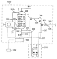
図1は、実施の形態1の給湯システム1000を示す図である。給湯システム1000は、貯湯タンク1及びヒートポンプ装置2を備える。燃焼式給湯機2000は、給湯システム1000の外部にある。既設の燃焼式給湯機2000に対して、給湯システム1000を後付けで並列的に設置することで、ハイブリッド給湯システムを構築することが可能である。ハイブリッド給湯システムを構築することで、燃焼式給湯機2000単体で使用する場合に比べて、ランニングコスト及び一次エネルギーの使用量を低減できる。
≪Device configuration≫
FIG. 1 is a diagram illustrating a hot
給湯システム1000は、貯湯タンク1及びヒートポンプ装置2に加えて、HP沸上げポンプ31、給水混合手段41、二熱源混合手段42、HP沸上げ往き配管301a、HP沸上げ戻り配管301b、給水配管302、高温導出配管303、給水混合配管304、給湯負荷配管305、中間給湯配管308、及び制御手段100を備える。
In addition to the hot
燃焼式給湯機2000は、給水を加熱して湯にする燃焼器5を備える。燃焼器5は、例えばガスまたは石油などの燃料の燃焼熱によって水を加熱する。燃焼器5の加熱能力すなわち単位時間当たりの加熱量は、ヒートポンプ装置2の加熱能力すなわち単位時間当たりの加熱量に比べて大きい。燃焼器5のエネルギー効率は、ヒートポンプ装置2のエネルギー効率に比べて低い。燃焼器5は、例えば燃料及び空気の量を調節することで加熱能力を調整可能に構成されてもよい。
Combustion-
給湯システム1000と燃焼式給湯機2000との間は、燃焼器給水配管306及び燃焼器給湯配管307を介して接続される。
The hot
貯湯タンク1は、湯水を貯留する。ヒートポンプ装置2は、貯湯タンク1から導かれた水を加熱して湯にする。ヒートポンプ装置2は、例えばインバータ制御などを用いて、加熱能力を変化可能に構成されてもよい。
The hot
給水配管302の一端は、水道等の水源に接続される。給水配管302の他端は、貯湯タンク1の下部に接続される。水源から供給される低温水が給水配管302を通って貯湯タンク1の下部に流入する。
One end of the
給湯システム1000は、蓄熱運転を実行できる。蓄熱運転は、ヒートポンプ装置2で加熱された湯すなわち高温水を貯湯タンク1に蓄積する運転である。蓄熱運転では、以下のようになる。ヒートポンプ装置2及びHP沸上げポンプ31が運転される。HP沸上げポンプ31が運転されると、貯湯タンク1とヒートポンプ装置2との間で水が循環する。貯湯タンク1内の水がHP沸上げ往き配管301aを通ってヒートポンプ装置2に送られる。ヒートポンプ装置2で加熱された湯は、HP沸上げ戻り配管301bを通って貯湯タンク1に導かれる。図示のように、HP沸上げポンプ31は、HP沸上げ戻り配管301bに比べて温度の低いHP沸上げ往き配管301aの途中に接続されることが望ましい。
The hot
高温導出配管303は、貯湯タンク1の上部から取り出された高温水を給水混合手段41の第一入口に導く。給水混合配管304は、給水配管302から分岐して、給水混合手段41の第二入口に低温水を導く。給水混合手段41の出口には、中間給湯配管308の上流端が接続されている。給水混合手段41は、貯湯タンク1から高温導出配管303を通って供給される湯と、給水混合配管304から供給される低温水とを混合または択一して、中間給湯配管308へ流入させる。中間給湯配管308の下流端は、二熱源混合手段42の第一入口に接続されている。
The high
燃焼器給水配管306は、給水配管302から分岐して、燃焼式給湯機2000の燃焼器5に低温水を導く。燃焼器給湯配管307は、燃焼器5で加熱された湯を、二熱源混合手段42の第二入口に導く。二熱源混合手段42の出口には、給湯負荷配管305の上流端が接続されている。給湯負荷配管305の下流側には、給湯負荷(図示省略)が接続される。給湯負荷は、例えば、給湯栓、浴槽、シャワー、のうちの少なくとも一つの給湯端末を含んでもよい。二熱源混合手段42は、貯湯タンク1から高温導出配管303及び中間給湯配管308を通って供給される湯と、燃焼式給湯機2000から燃焼器給湯配管307を通って供給される湯とを混合または択一して、給湯負荷配管305へ流入させる。当該混合または択一された湯は、給湯負荷配管305を通って、給湯負荷へ供給される。
The combustor
上述したように、本実施の形態1では、貯湯タンク1からの湯が、給水混合手段41、二熱源混合手段42、給湯負荷、の順で流れる。本実施の形態1は、燃焼式給湯機2000の燃焼器5で加熱された湯を、給水混合手段41の下流側の二熱源混合手段42にて混合可能な例を示している。
As described above, in the first embodiment, hot water from the hot
制御手段100は、ヒートポンプ装置2、HP沸上げポンプ31、給水混合手段41、及び二熱源混合手段42の各々の動作を制御する。
The
貯湯タンク1には、高さ方向に間隔をおいて、貯湯温度検出手段501a〜501fが設けられている。なお、ここでは、貯湯温度検出手段の個数が6個の例を図示したが、この個数はこの例に限られるものではなく、貯湯タンク1の内部の温度分布を測るのに必要最低限な数の温度検出手段を設けるようにしてもよい。
The hot
HP沸上げ戻り配管301bには、ヒートポンプ装置2の下流側にて湯水の温度を検出するHP沸上げ温度検出手段502が設けられている。給水配管302には、水源から供給される低温水の温度(以下、「給水温度」と称する)を検出するための給水温度検出手段504が設けられている。貯湯タンク1の上部には、貯湯タンク1の上部から取り出された湯の温度(以下、「タンク給湯温度」と称する)を検出する導出温度検出手段503が設けられている。燃焼器5の下流側であって給湯システム1000の内部の燃焼器給湯配管307には、燃焼式給湯温度検出手段507が設けられている。燃焼式給湯温度検出手段507は、燃焼式給湯機2000から二熱源混合手段42へ供給される湯の温度(以下、「燃焼式給湯温度」と称する)を検出する。中間給湯配管308には、給水混合手段41と二熱源混合手段42との間を流れる湯水の温度を検出する中間給湯温度検出手段508が設けられている。給湯負荷配管305には、給湯負荷に供給される湯水の温度(以下、「給湯負荷温度」と称する)を検出する給湯負荷温度検出手段505が設けられている。給湯負荷配管305には、給湯負荷に供給される湯水の流量(以下、「給湯負荷流量」と称する)を検出する給湯負荷流量検出手段601が設けられている。
The HP boiling
図2は、実施の形態1の給湯システム1000のブロック図である。制御手段100は、ヒートポンプ装置2を制御するHP沸上げ制御手段105と、給水混合手段41及び二熱源混合手段42を制御する混合制御手段106と、リモコン102と、HP沸上げポンプ31を制御するポンプ制御手段108とを備える。
FIG. 2 is a block diagram of hot
リモコン102は、ユーザー操作を受け付ける操作端末またはユーザーインターフェース装置の例である。リモコン102は、例えば、浴室、台所などに設置されてもよい。リモコン102は、制御手段100の本体に対し、有線または無線により、双方向にデータ通信可能に接続される。リモコン102は、温度目標値設定手段107を備える。温度目標値設定手段107は、ユーザーが給湯負荷温度の目標値を設定することを可能にする。リモコン102は、例えば液晶ディスプレイのような表示装置を備えてもよい。リモコン102は、ブザー、音声ガイダンスを出力する音声出力装置などを備えてもよい。複数台のリモコン102が備えられてもよい。
The
制御手段100には、日時検出手段(タイマー)509、貯湯温度検出手段501a〜501f、HP沸上げ温度検出手段502、導出温度検出手段503、給水温度検出手段504、給湯負荷温度検出手段505、燃焼式給湯温度検出手段507、中間給湯温度検出手段508、及び、給湯負荷流量検出手段601の各々が検出した情報が入力される。制御手段100は、入力されたこれらの情報に基づいて、ヒートポンプ装置2、HP沸上げポンプ31、給水混合手段41、及び二熱源混合手段42の各々の動作を制御する。
The control means 100 includes date and time detection means (timer) 509, hot water storage temperature detection means 501a to 501f, HP boiling temperature detection means 502, derived temperature detection means 503, feed water temperature detection means 504, hot water supply load temperature detection means 505, combustion Information detected by each of the hot water supply temperature detection means 507, the intermediate hot water supply temperature detection means 508, and the hot water supply load flow rate detection means 601 is input. The
HP沸上げ制御手段105は、ヒートポンプ装置2の起動及び停止、並びに、ヒートポンプ装置2の運転中の加熱能力などを制御する。
The HP boiling control means 105 controls the starting and stopping of the
混合制御手段106は、給水混合手段41及び二熱源混合手段42における混合比率を制御する。混合制御手段106は、給湯負荷温度検出手段505または中間給湯温度検出手段508で検出される温度が、給湯負荷温度の目標値に近づくように、給水混合手段41における、貯湯タンク1から高温導出配管303を通って供給される湯と、給水混合配管304から供給される低温水との混合または択一を制御してもよい。混合制御手段106は、給湯負荷温度検出手段505で検出される給湯負荷温度が、給湯負荷温度の目標値に近づくように、二熱源混合手段42における、貯湯タンク1から高温導出配管303及び中間給湯配管308を通って供給される湯と、燃焼式給湯機2000から燃焼器給湯配管307を通って供給される湯との混合または択一を制御してもよい。
The mixing control means 106 controls the mixing ratio in the feed water mixing means 41 and the two heat source mixing means 42. The mixing control means 106 is a high temperature outlet pipe from the hot
ポンプ制御手段108は、蓄熱運転のときに、HP沸上げポンプ31の回転速度を制御することで、水の循環流量を調節してもよい。ポンプ制御手段108は、HP沸上げ温度検出手段502で検出される温度が目標値に近づくように、HP沸上げポンプ31の動作を制御してもよい。
The pump control means 108 may adjust the circulating flow rate of water by controlling the rotational speed of the
以上、実施の形態1の給湯システム1000の構成を説明した。次に、実施の形態1の給湯システム1000の動作について説明する。
The configuration of hot
≪基本的動作≫
まず、給湯システム1000の基本的な動作を説明する。
≪Basic operation≫
First, the basic operation of the hot
[タンク給湯動作]
タンク給湯動作は、以下のような動作である。蓄熱運転により、ヒートポンプ装置2で加熱した湯を貯湯タンク1に溜める。給湯負荷の湯の需要が発生した場合に、貯湯タンク1に貯留された湯を、給水混合手段41にて低温水と混合することで、目標温度に調節した湯を給湯負荷へ送る。
[Tank hot water operation]
The tank hot water supply operation is as follows. Hot water heated by the
[燃焼式給湯動作]
燃焼式給湯動作では、二熱源混合手段42を燃焼器側全開とし、燃焼式給湯機2000の燃焼器5で加熱した湯を給湯負荷に送ってもよい。燃焼器側全開とは、二熱源混合手段42において、燃焼式給湯機2000から燃焼器給湯配管307を通って供給される湯を択一する状態に相当する。主として、貯湯タンク1内の貯湯温度が十分に高くない場合に、燃焼式給湯動作を行う。
[Combustion hot water supply operation]
In the combustion type hot water supply operation, the two heat source mixing means 42 may be fully opened on the combustor side, and the hot water heated by the
一般的に、燃焼器5は、流量が過小であると温度調節が困難であるという特性を有する。温度調節が困難な状態で給湯することを避けるために、すなわち安全性を優先するために、燃焼式給湯機2000は、燃焼器5を通過する水の流量が閾値(以下、「燃焼器温調可能流量」と称する)より低い場合には、燃焼器5を運転しないように制御する。
Generally, the
[蓄熱運転]
燃焼式給湯動作に比べて、タンク給湯動作の方が、高効率であり、ランニングコスト及び一次エネルギーの使用量を低減できる。なるべく燃焼式給湯動作を行わないで済ませるために、制御手段100は、貯湯タンク1の湯切れが発生しないように、蓄熱運転を実施する。蓄熱運転では、レジオネラ殺菌、所定のタンク容量に所定の蓄熱量を収容するために必要な貯湯温度、などを根拠として、貯湯タンク1に貯留する湯の温度の目標値を定める。蓄熱運転のとき、制御手段100は、HP沸上げ温度検出手段502で検知される温度が、当該目標値に等しくなるように、ヒートポンプ装置2及びHP沸上げポンプ31を制御する。
[Heat storage operation]
Compared to the combustion hot water supply operation, the tank hot water supply operation is more efficient, and the running cost and the amount of primary energy used can be reduced. In order to avoid performing the combustion type hot water supply operation as much as possible, the control means 100 performs the heat storage operation so that the hot
≪特徴的な動作≫
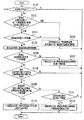
以下、本実施の形態1の特徴的な動作について図3を用いて説明する。図3は、実施の形態1において実行されるルーチンのフローチャートである。本実施の形態では、制御手段100が図3のフローチャートの処理を実行する。本フローチャートのルーチンは、周期的に繰り返し実行される。
≪Characteristic action≫
The characteristic operation of the first embodiment will be described below with reference to FIG. FIG. 3 is a flowchart of a routine executed in the first embodiment. In the present embodiment, the
図3のステップS3101では、給湯負荷へ湯が流れているか否かが判定される。例えば、給湯負荷流量検出手段601の検出値に基づいて、給湯負荷へ湯が流れているか否かを判定してもよい。給湯負荷へ湯が流れていない場合には、ルーチンを終了する。 In step S3101 of FIG. 3, it is determined whether hot water is flowing into the hot water supply load. For example, it may be determined whether hot water is flowing into the hot water supply load based on the detected value of the hot water supply load flow rate detection means 601. If hot water is not flowing into the hot water supply load, the routine is terminated.
給湯負荷へ湯が流れている場合には、ステップS3101からステップS3102へ移行する。ステップS3102では、燃焼式給湯機2000の運転の要否が判定される。ステップS3102では、以下のようにしてもよい。タンク給湯温度が、給湯負荷温度の目標値以上であれば、燃焼式給湯機2000の運転が不要と判定してもよい。タンク給湯温度が、給湯負荷温度の目標値未満であれば、燃焼式給湯機2000の運転が必要と判定してもよい。タンク給湯温度は、導出温度検出手段503により検出できる。
When hot water is flowing into the hot water supply load, the process proceeds from step S3101 to step S3102. In step S <b> 3102, it is determined whether or not the combustion
燃焼式給湯機2000の運転が不要と判定された場合には、ステップS3102からステップS3103へ移行する。ステップS3103では、以下のようにする。二熱源混合手段42を燃焼器側全閉とする。燃焼器側全閉とは、二熱源混合手段42において、貯湯タンク1から供給される湯を択一する状態に相当する。給湯負荷温度検出手段505で検出される給湯負荷温度が目標値に近づくように、給水混合手段41の動作が制御される。ステップS3103の後、ルーチンを終了する。
When it is determined that the operation of the
燃焼式給湯機2000の運転が必要と判定された場合には、ステップS3102からステップS3104へ移行する。ステップS3104では、給湯負荷流量検出手段601で検出される給湯負荷流量を、基準値である下限流量と比較する。下限流量は、燃焼器温調可能流量に等しい値、または燃焼器温調可能流量に比べてやや大きい値になるように、予め設定されている。
When it is determined that the operation of the combustion hot
給湯負荷流量が下限流量に満たない場合には、ステップS3104から、上述したステップS3103へ移行する。給湯負荷流量が下限流量以上である場合には、ステップS3104からステップS3105へ移行する。 When the hot water supply load flow rate is less than the lower limit flow rate, the process proceeds from step S3104 to step S3103 described above. When the hot water supply load flow rate is equal to or higher than the lower limit flow rate, the process proceeds from step S3104 to step S3105.
ステップS3105では、給湯負荷温度検出手段505で検出される給湯負荷温度が目標値に近づくように、給水混合手段41の動作が制御される。ステップS3105では、給水混合手段41は、高温導出配管303側に全開で給水混合配管304側に全閉の状態に制御されてもよい。すなわち、給水混合手段41は、貯湯タンク1から高温導出配管303を通って供給される湯を択一する状態に制御されてもよい。ステップS3105からステップS3106へ移行する。
In step S3105, the operation of the feed water mixing means 41 is controlled so that the hot water supply load temperature detected by the hot water supply load temperature detection means 505 approaches the target value. In step S3105, the feed water mixing means 41 may be controlled to be fully open on the high
ステップS3106では、燃焼式給湯機2000の燃焼器5から二熱源混合手段42へ供給される湯の流量(以下、「燃焼式給湯流量」と称する)を検出し、その検出された燃焼式給湯流量を下限流量と比較する。燃焼式給湯流量は、以下のようにして検出してもよい。給湯負荷流量検出手段601で検出される給湯負荷流量と、給湯負荷温度検出手段505で検出される給湯負荷温度と、中間給湯温度検出手段508で検出される温度と、燃焼式給湯温度検出手段507で検出される燃焼式給湯温度とに基づいて、燃焼式給湯流量の推定値を計算できる。当該推定値を燃焼式給湯流量の検出値として用いることができる。または、燃焼器給水配管306または燃焼器給湯配管307に設置した流量センサ(図示省略)により、燃焼式給湯流量を直接検出してもよい。
In step S3106, the flow rate of hot water supplied to the two heat source mixing means 42 from the
燃焼式給湯流量が下限流量に満たない場合には、ステップS3106からステップS3107へ移行する。ステップS3107では、燃焼式給湯流量が下限流量に近づくように、二熱源混合手段42が制御される。例えば、二熱源混合手段42を燃焼器給湯配管307側に全開とし、給湯負荷の全量を燃焼式給湯機2000側から供給するようにしてもよい。ステップS3107の後、ルーチンを終了する。
When the combustion hot water supply flow rate is less than the lower limit flow rate, the process proceeds from step S3106 to step S3107. In step S3107, the two heat source mixing means 42 is controlled so that the combustion hot water supply flow rate approaches the lower limit flow rate. For example, the two heat source mixing means 42 may be fully opened to the combustor hot
燃焼式給湯流量が下限流量以上である場合には、ステップS3106からステップS3108へ移行する。ステップS3108では、給水混合手段41及び二熱源混合手段42の各々の動作が安定したかどうかを確認する。給水混合手段41及び二熱源混合手段42の各々の動作がまだ安定していない場合には、ルーチンを終了する。給水混合手段41及び二熱源混合手段42の各々の動作が安定している場合には、ステップS3108からステップS3109へ移行する。
If the combustion hot water supply flow rate is equal to or greater than the lower limit flow rate, the process moves from step S3106 to step S3108. In step S3108, it is confirmed whether each operation | movement of the feed water mixing means 41 and the two heat-source mixing means 42 was stabilized. If the operations of the feed water mixing means 41 and the two heat source mixing means 42 are not yet stable, the routine is terminated. When the operations of the feed
ステップS3109では、給湯負荷温度検出手段505で検出される給湯負荷温度が目標値以上であるという第一条件と、燃焼式給湯流量の検出値が下限流量より大きいという第二条件とが共に満たされているかどうかを判断する。第一条件及び第二条件が共に満たされている場合には、その時点より燃焼式給湯流量を低下させても、給湯負荷へ供給される湯の温度を目標値以上に維持することが可能であると考えられる。第一条件及び第二条件が共に満たされている場合には、ステップS3109からステップS3110へ移行する。ステップS3110では、燃焼式給湯流量が減少する方向に二熱源混合手段42の開度を操作する。ステップS3110の後、ルーチンを終了する。 In step S3109, the first condition that the hot water supply load temperature detected by hot water supply load temperature detecting means 505 is equal to or higher than the target value and the second condition that the detected value of the combustion hot water supply flow rate is larger than the lower limit flow rate are both satisfied. Determine if you are. When both the first condition and the second condition are satisfied, the temperature of the hot water supplied to the hot water supply load can be maintained at a target value or higher even if the combustion hot water flow rate is reduced from that point. It is believed that there is. When both the first condition and the second condition are satisfied, the process proceeds from step S3109 to step S3110. In step S3110, the opening degree of the two heat source mixing means 42 is manipulated in the direction in which the combustion hot water supply flow rate decreases. After step S3110, the routine ends.
ステップS3109で第一条件及び第二条件の少なくとも一方が満たされていない場合には、ステップS3109からステップS3111へ移行する。ステップS3111では、給湯負荷温度検出手段505で検出される給湯負荷温度が目標値未満であるかどうかを判断する。給湯負荷温度が目標値未満でない場合、すなわち給湯負荷温度が目標値以上である場合には、ルーチンを終了する。給湯負荷温度が目標値未満である場合には、ステップS3111からステップS3112へ移行する。ステップS3112では、燃焼式給湯流量を増加させる方向に、二熱源混合手段42の開度を操作する。これにより、給湯負荷温度を目標値に近づけることができる。ステップS3112の後、ルーチンを終了する。 If at least one of the first condition and the second condition is not satisfied in step S3109, the process proceeds from step S3109 to step S3111. In step S3111, it is determined whether or not the hot water supply load temperature detected by hot water supply load temperature detecting means 505 is less than the target value. If the hot water supply load temperature is not lower than the target value, that is, if the hot water supply load temperature is equal to or higher than the target value, the routine is terminated. When the hot water supply load temperature is lower than the target value, the process proceeds from step S3111 to step S3112. In step S3112, the opening degree of the two heat source mixing means 42 is operated in the direction of increasing the combustion hot water supply flow rate. Thereby, the hot water supply load temperature can be brought close to the target value. After step S3112, the routine ends.
本実施の形態であれば、給湯負荷流量が下限流量に満たない場合には、ステップS3104からステップS3103へ移行することで、二熱源混合手段42において、貯湯タンク1から供給される湯が択一されるようにする。これにより、以下の効果が得られる。給湯負荷流量が下限流量に満たない場合には、燃焼式給湯機2000の燃焼器5を通過する水の流量が燃焼器温調可能流量に満たなくなることで、燃焼器5が運転されない可能性がある。燃焼器5が運転されない状態で燃焼器給湯配管307からの低温水が二熱源混合手段42で混合されると、給湯負荷温度が目標値に比べて大幅に低くなる可能性がある。本実施の形態であれば、給湯負荷流量が下限流量に満たない場合には、二熱源混合手段42において、貯湯タンク1から供給される湯が択一されるようにすることで、燃焼器給湯配管307からの低温水が二熱源混合手段42で混合されることを確実に防止できる。そのため、給湯負荷温度が目標値に比べて大幅に低くなる事態が生ずることを確実に防止できる。
In the present embodiment, when the hot water supply load flow rate is less than the lower limit flow rate, the process proceeds from step S3104 to step S3103, whereby the hot water supplied from the hot
本実施の形態であれば、導出温度検出手段503により検出されるタンク給湯温度が、給湯負荷温度の目標値以上である場合には、ステップS3102からステップS3103へ移行することで、二熱源混合手段42において、貯湯タンク1から供給される湯が択一されるようにする。これにより、ランニングコストの低いタンク給湯動作を優先的に実行できる。また、タンク給湯温度が給湯負荷温度の目標値に満たない場合には、二熱源混合手段42において、貯湯タンク1から供給される湯と、燃焼式給湯機2000から供給される湯とが混合されるようにする。これにより、タンク給湯温度が不十分であるときでも、給湯負荷に供給される湯の温度を目標値に等しくできる。
In the present embodiment, when the tank hot water temperature detected by the derived temperature detection means 503 is equal to or higher than the target value of the hot water supply load temperature, the process proceeds from step S3102 to step S3103, whereby the two heat source mixing means At 42, hot water supplied from the hot
本実施の形態であれば、ステップS3109〜ステップS3111の処理により、以下の効果が得られる。貯湯タンク1から供給される湯と、燃焼式給湯機2000から供給される湯とを二熱源混合手段42で混合する場合に、給湯負荷温度が目標値以上になり、かつ、燃焼式給湯流量が下限流量以上になる範囲において、燃焼式給湯流量が最少になるように制御できる。そのため、給湯負荷に供給される湯の温度を確実に目標値以上にすることと、ランニングコストの低減とを両立できる。
In the present embodiment, the following effects can be obtained by the processing in steps S3109 to S3111. When the hot water supplied from the hot
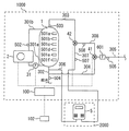
図4は、実施の形態1の給湯システム1000の変形例を示す図である。図4に示す変形例の給湯システム1000は、以下の点で、図1の給湯システム1000と異なる。高温導出配管303は、貯湯タンク1の上部と、二熱源混合手段42の第一入口との間をつなぐ。中間給湯配管308は、二熱源混合手段42の出口と、給水混合手段41の第二入口との間をつなぐ。本発明では、図4に示す給湯システム1000のように、給水混合手段41の上流側で、貯湯タンク1から供給される湯と燃焼式給湯機2000から供給される湯とを混合可能に構成してもよい。図4に示す給湯システム1000では、給湯負荷流量検出手段601で検出される給湯負荷流量と、給湯負荷温度検出手段505で検出される給湯負荷温度と、中間給湯温度検出手段508で検出される温度と、燃焼式給湯温度検出手段507で検出される燃焼式給湯温度と、導出温度検出手段503で検出されるタンク給湯温度と、給水温度検出手段504で検出される給水温度とに基づいて、燃焼式給湯流量の推定値を計算できる。当該推定値を燃焼式給湯流量の検出値として用いることができる。または、燃焼器給水配管306または燃焼器給湯配管307に設置した流量センサ(図示省略)により、燃焼式給湯流量を直接検出してもよい。
FIG. 4 is a diagram illustrating a modification of the hot
実施の形態1では、ユーザーの利便性を向上させることなどを目的として、以下のようにしてもよい。
(1)給湯システム1000は、下限流量の値をユーザーが設定可能にする手段を備えてもよい。例えば、ユーザーがリモコン102を操作することで下限流量の値を変更または入力できるように構成してもよい。下限流量の値をユーザーが設定可能にすることで、既設の燃焼式給湯機2000ごとの多様な燃焼器温調可能流量に応じて、下限流量をより適切な値に設定できる。
In the first embodiment, the following may be performed for the purpose of improving user convenience.
(1) The hot
(2)給湯システム1000は、給湯負荷へ供給される湯が、貯湯タンク1からの湯であるか、燃焼式給湯機2000からの湯であるか、貯湯タンク1からの湯と燃焼式給湯機2000からの湯とが混合された湯であるか、に関する情報を報知する手段を備えてもよい。例えば、当該情報をリモコン102の表示装置に表示してもよいし、当該情報をリモコン102から音声ガイダンスとして出力してもよい。当該情報をユーザーに報知することで、ユーザーは、例えば、自身の給湯行為を、より省エネルギー・低費用にしうる。例えば、貯湯タンク1からの湯に比べてランニングコストが高い燃焼式給湯機2000からの湯が給湯負荷へ供給される場合には、ユーザーは、湯の使用を必要最小限に控えるようにすればよい。また、入浴などの使用湯量の多い行為については、ユーザーは、ランニングコストの低い貯湯タンク1からの湯が給湯負荷へ供給される状態のときに実施すればよい。
(2) The hot
(3)給湯システム1000は、貯湯タンク1からの湯を給湯負荷へ供給する状態と、燃焼式給湯機2000からの湯を給湯負荷へ供給する状態と、貯湯タンク1からの湯と燃焼式給湯機2000からの湯とが混合された湯を給湯負荷へ供給する状態と、のうちの、いずれかの状態から他の状態への変化に関する情報を報知する手段を備えてもよい。例えば、当該変化をリモコン102の表示装置に予告表示してもよいし、当該変化をリモコン102から音声ガイダンスにより予告してもよいし、ブザーを鳴らすことで当該変化を予告してもよい。上記の変化の際には、湯水の回路が切り替わることで、給湯負荷での湯温の変動が発生する可能性がある。当該変化の情報をユーザーに報知することで、ユーザーは、当該変化の際にシャワーを一時的に避けるなどの措置をとることが可能となり、給湯行為における利便性が向上する。
(3) The hot
(4)給湯システム1000は、給湯負荷温度検出手段505で検出される給湯負荷温度が目標値に達しない場合に、燃焼式給湯機2000の給湯設定温度を高くすることをユーザーに勧める手段を備えてもよい。例えば、給湯負荷温度検出手段505で検出される給湯負荷温度が目標値に達しない場合に、燃焼式給湯機2000の給湯設定温度を高くすることを勧める内容のメッセージを、リモコン102の表示装置に表示したり、リモコン102から音声ガイダンスとして出力してもよい。給湯負荷温度検出手段505で検出される給湯負荷温度が目標値に達しないことの原因が、燃焼式給湯機2000の給湯設定温度が給湯負荷温度の目標値より低くなっていることにある場合が考えられる。そのような場合に、上記メッセージをユーザーに報知することで、利便性が向上する。
(4) The hot
実施の形態2.
次に、図5を参照して、実施の形態2について説明するが、上述した実施の形態1との相違点を中心に説明し、同一部分または相当部分については説明を簡略化または省略する。実施の形態2の給湯システム1000のハードウェア機器の構成は、実施の形態1と同じであるので、説明を省略する。
Next, the second embodiment will be described with reference to FIG. 5. The description will focus on the differences from the first embodiment described above, and the description of the same or corresponding parts will be simplified or omitted. Since the configuration of the hardware device of hot
図5は、実施の形態2において実行されるルーチンのフローチャートである。本実施の形態では、制御手段100が図5のフローチャートの処理を実行する。本フローチャートのルーチンは、周期的に繰り返し実行される。
FIG. 5 is a flowchart of a routine executed in the second embodiment. In the present embodiment, the
図5のステップS5101では、蓄熱運転の実行が必要であるか否かを判定する。当該判定は、貯湯温度検出手段501a〜501fで検知される蓄熱量または貯湯量に基づいて行われてもよい。当該判定は、ユーザーの過去の給湯使用実績を学習した情報をさらに加味して行われてもよい。蓄熱運転が不要と判定された場合には、ステップS5101からステップS5102へ移行する。ステップS5102では、蓄熱運転を停止する。ステップS5102からステップS5107へ移行する。
In step S5101 of FIG. 5, it is determined whether or not it is necessary to execute the heat storage operation. The determination may be performed based on the amount of stored heat or the amount of stored hot water detected by the stored hot water
蓄熱運転が必要と判定された場合には、ステップS5101からステップS5103へ移行する。ステップS5103では、蓄熱運転が実行中であるか否かを判定する。蓄熱運転が実行中である場合には、そのまま蓄熱運転を継続し、ステップS5107へ移行する。蓄熱運転が実行中でない場合には、ステップS5103からステップS5104へ移行する。 If it is determined that the heat storage operation is necessary, the process proceeds from step S5101 to step S5103. In step S5103, it is determined whether the heat storage operation is being performed. When the heat storage operation is being executed, the heat storage operation is continued as it is, and the process proceeds to step S5107. When the heat storage operation is not being executed, the process proceeds from step S5103 to step S5104.
ステップS5104では、攪拌運転の実行が必要であるか否かを判定する。攪拌運転は、貯湯タンク1の内部を攪拌することで貯湯タンク1の内部の水温を均一に近づける運転である。攪拌運転は、ヒートポンプ装置2を停止したままでHP沸上げポンプ31を最高速度で駆動する運転でもよい。貯湯タンク1の上部の温度と下部の温度との温度差が基準に比べて大きい場合に攪拌運転が必要と判定し、当該温度差が当該基準に比べて小さい場合に攪拌運転が不要と判定してもよい。
In step S5104, it is determined whether it is necessary to perform a stirring operation. The agitation operation is an operation in which the water temperature inside the hot
攪拌運転が不要と判定された場合には、ステップS5104からステップS5105へ移行する。ステップS5105では、蓄熱運転を実行する。ステップS5105からステップS5107へ移行する。 If it is determined that the stirring operation is unnecessary, the process proceeds from step S5104 to step S5105. In step S5105, a heat storage operation is performed. The process proceeds from step S5105 to step S5107.
攪拌運転が必要と判定された場合には、ステップS5104からステップS5106へ移行する。ステップS5105では、攪拌運転を実行する。 If it is determined that the stirring operation is necessary, the process proceeds from step S5104 to step S5106. In step S5105, a stirring operation is executed.
ステップS5107では、給湯負荷へ湯が流れているか否かが判定される。例えば、給湯負荷流量検出手段601の検出値に基づいて、給湯負荷へ湯が流れているか否かを判定してもよい。給湯負荷へ湯が流れていない場合には、ルーチンを終了する。 In step S5107, it is determined whether hot water is flowing into the hot water supply load. For example, it may be determined whether hot water is flowing into the hot water supply load based on the detected value of the hot water supply load flow rate detection means 601. If hot water is not flowing into the hot water supply load, the routine is terminated.
給湯負荷へ湯が流れている場合には、ステップS5107からステップS5108へ移行する。ステップS5108では、攪拌運転が実行中であるか否かを判定する。攪拌運転が実行中でない場合には、ステップS5108からステップS5109へ移行する。ステップS5109では、実施の形態1の図3で説明した方法により、給湯動作を行う。ステップS5109の後、ルーチンを終了する。 When hot water is flowing into the hot water supply load, the process proceeds from step S5107 to step S5108. In step S5108, it is determined whether the stirring operation is being executed. When the stirring operation is not being executed, the process proceeds from step S5108 to step S5109. In step S5109, the hot water supply operation is performed by the method described with reference to FIG. After step S5109, the routine ends.
攪拌運転が実行中である場合には、ステップS5108からステップS5110へ移行する。ステップS5110では、撹拌運転と給湯動作が同時に実行される。ステップS5110では、二熱源混合手段42を燃焼器側全開とすることで、貯湯タンク1の湯を使用せず、燃焼式給湯機2000から供給される湯を用いて給湯を行う。ステップS5110の後、ルーチンを終了する。
When the stirring operation is being executed, the process proceeds from step S5108 to step S5110. In step S5110, the stirring operation and the hot water supply operation are executed simultaneously. In step S5110, hot water is supplied using the hot water supplied from the combustion
本実施の形態であれば、蓄熱運転を行う前に、攪拌運転を行うことで、貯湯タンク1の内部の水温を均一に近づけることができる。攪拌運転の後に蓄熱運転を行うことで、蓄熱運転の実行中にヒートポンプ装置2に入る水の温度を、安定した状態、例えば一定に近い状態、にすることができる。蓄熱運転の実行中にヒートポンプ装置2への入水温度が安定することで、入水温度の変動に応じてヒートポンプ装置2の冷媒回路の膨張弁開度あるいは圧縮機周波数などを逐次調整する必要が無くなり、より容易に安定した高効率運転を実現することができる。
If it is this Embodiment, before performing heat storage operation, the water temperature inside the hot
攪拌運転を行うと、貯湯タンク1の全域が中低温の状態になる。本実施の形態であれば、貯湯タンク1の全域が中低温の状態になっても、燃焼式給湯機2000から供給される湯を用いて給湯できるので、問題無い。
When the agitation operation is performed, the entire area of the hot
本実施の形態であれば、攪拌運転の実行中は、ステップS5110の処理を行うことで、攪拌運転の非実行中に比べて、燃焼式給湯機2000から供給される湯の割合が高くなるように二熱源混合手段42が制御される。これにより、攪拌運転に伴う貯湯タンク1内の温度変動が給湯負荷へ供給される湯の温度に影響を及ぼすことを防止できる。本実施の形態では、ステップS5110で、二熱源混合手段42を燃焼器側全開としているが、給湯負荷へ供給される湯の温度変動が許容範囲となる水準であれば、貯湯タンク1からの湯を二熱源混合手段42で混合してもよい。
According to the present embodiment, during the agitation operation, the process of step S5110 is performed so that the proportion of hot water supplied from the combustion hot
1 貯湯タンク、 2 ヒートポンプ装置、 5 燃焼器、 31 HP沸上げポンプ、 41 給水混合手段、 42 二熱源混合手段、 100 制御手段、 102 リモコン、 105 HP沸上げ制御手段、 106 混合制御手段、 107 温度目標値設定手段、 108 ポンプ制御手段、 301a HP沸上げ往き配管、 301b HP沸上げ戻り配管、 302 給水配管、 303 高温導出配管、 304 給水混合配管、 305 給湯負荷配管、 306 燃焼器給水配管、 307 燃焼器給湯配管、 308 中間給湯配管、 501a〜501f 貯湯温度検出手段、 502 HP沸上げ温度検出手段、 503 導出温度検出手段、 504 給水温度検出手段、 505 給湯負荷温度検出手段、 507 燃焼式給湯温度検出手段、 508 中間給湯温度検出手段、 601 給湯負荷流量検出手段、 1000 給湯システム、 2000 燃焼式給湯機
DESCRIPTION OF
Claims (9)
給湯負荷につながる給湯負荷配管と、
前記給湯負荷配管の上流側において、前記貯湯タンクから供給される湯と、外部の燃焼式給湯機から供給される湯とを択一または混合する混合手段と、
前記給湯負荷配管を流れる湯の流量である給湯負荷流量を検出する手段と、
前記混合手段を制御する制御手段と、
を備え、
前記給湯負荷流量が下限流量に満たない場合に、前記貯湯タンクから供給される湯が択一されるように前記混合手段が制御される給湯システム。 A hot water storage tank,
Hot water supply load piping that leads to hot water supply load,
On the upstream side of the hot water supply load pipe, mixing means for alternatively or mixed hot water supplied from the hot water storage tank and hot water supplied from an external combustion hot water supply machine,
Means for detecting a hot water supply load flow rate that is a flow rate of hot water flowing through the hot water supply load piping;
Control means for controlling the mixing means;
With
A hot water supply system in which the mixing means is controlled so that hot water supplied from the hot water storage tank is selected when the hot water supply load flow rate is less than the lower limit flow rate.
前記貯湯タンクから供給される湯の温度が前記給湯負荷温度の目標値以上である場合には前記貯湯タンクから供給される湯が択一されるように前記混合手段が制御され、前記貯湯タンクから供給される湯の温度が前記目標値に満たない場合には前記貯湯タンクから供給される湯と前記燃焼式給湯機から供給される湯とを混合するように前記混合手段が制御される請求項1に記載の給湯システム。 Means for detecting a hot water supply load temperature which is a temperature of hot water flowing through the hot water supply load pipe;
When the temperature of the hot water supplied from the hot water storage tank is equal to or higher than the target value of the hot water supply load temperature, the mixing means is controlled so that the hot water supplied from the hot water storage tank is selected. The mixing means is controlled to mix the hot water supplied from the hot water storage tank and the hot water supplied from the combustion hot water supply when the temperature of the supplied hot water is less than the target value. The hot water supply system according to 1.
前記貯湯タンクから供給される湯と前記燃焼式給湯機から供給される湯とを混合する場合に、前記給湯負荷温度が前記目標値以上になり、かつ、前記燃焼式給湯流量が前記下限流量以上になる範囲において、前記燃焼式給湯流量が最少になるように前記混合手段が制御される請求項2に記載の給湯システム。 Means for detecting a combustion-type hot water supply flow rate that is a flow rate of hot water supplied from the combustion-type water heater to the mixing means;
When mixing the hot water supplied from the hot water storage tank and the hot water supplied from the combustion hot water supply device, the hot water supply load temperature is equal to or higher than the target value, and the combustion hot water supply flow rate is equal to or higher than the lower limit flow rate. The hot water supply system according to claim 2, wherein the mixing means is controlled so that the combustion type hot water supply flow rate is minimized within a range.
前記給湯負荷温度が目標値に達しない場合に、前記燃焼式給湯機の給湯設定温度を高くすることをユーザーに勧める手段を備える請求項1から請求項6のいずれか一項に記載の給湯システム。 Means for detecting a hot water supply load temperature which is a temperature of hot water flowing through the hot water supply load pipe;
The hot water supply system according to any one of claims 1 to 6, further comprising means for recommending a user to increase a hot water supply set temperature of the combustion hot water heater when the hot water supply load temperature does not reach a target value. .
前記ヒートポンプ装置で加熱された湯を前記貯湯タンクに蓄積する運転の前に、前記貯湯タンクの内部を攪拌する攪拌運転を行う手段と、
を備える請求項1から請求項7のいずれか一項に記載の給湯システム。 A heat pump device for heating water;
Means for performing an agitation operation of agitating the interior of the hot water storage tank before the operation of accumulating the hot water heated by the heat pump device in the hot water storage tank;
The hot-water supply system as described in any one of Claims 1-7 provided with these.
Priority Applications (1)
| Application Number | Priority Date | Filing Date | Title |
|---|---|---|---|
| JP2016079552A JP6583110B2 (en) | 2016-04-12 | 2016-04-12 | Hot water system |
Applications Claiming Priority (1)
| Application Number | Priority Date | Filing Date | Title |
|---|---|---|---|
| JP2016079552A JP6583110B2 (en) | 2016-04-12 | 2016-04-12 | Hot water system |
Publications (2)
| Publication Number | Publication Date |
|---|---|
| JP2017190892A true JP2017190892A (en) | 2017-10-19 |
| JP6583110B2 JP6583110B2 (en) | 2019-10-02 |
Family
ID=60084740
Family Applications (1)
| Application Number | Title | Priority Date | Filing Date |
|---|---|---|---|
| JP2016079552A Active JP6583110B2 (en) | 2016-04-12 | 2016-04-12 | Hot water system |
Country Status (1)
| Country | Link |
|---|---|
| JP (1) | JP6583110B2 (en) |
Cited By (1)
| Publication number | Priority date | Publication date | Assignee | Title |
|---|---|---|---|---|
| CN114234437A (en) * | 2021-12-13 | 2022-03-25 | 华帝股份有限公司 | Water heater and control method thereof |
Citations (9)
| Publication number | Priority date | Publication date | Assignee | Title |
|---|---|---|---|---|
| US4345583A (en) * | 1978-08-21 | 1982-08-24 | Pechiney Ugine Kuhlmann | Water heater using solar and non-solar energy |
| JPH08327144A (en) * | 1995-05-29 | 1996-12-13 | Sunazaki Seisakusho:Kk | Control method of electric hot water supplier |
| JP2001124356A (en) * | 1999-10-28 | 2001-05-11 | Noritz Corp | Method for controlling instantaneous hot water output for instantaneous hot water outputting device |
| JP2003056908A (en) * | 2001-08-10 | 2003-02-26 | Noritz Corp | Heating method for water heater utilizing external heat source |
| JP2005214452A (en) * | 2004-01-27 | 2005-08-11 | Denso Corp | Hot water storage water heater |
| JP2012127628A (en) * | 2010-12-17 | 2012-07-05 | Panasonic Corp | Hot water supply system |
| JP2013224790A (en) * | 2012-04-20 | 2013-10-31 | Sharp Corp | Storage type water heater |
| JP2014169812A (en) * | 2013-03-04 | 2014-09-18 | Purpose Co Ltd | Tank hot water supply device, hot water supply method and hot water supply system |
| JP2015031455A (en) * | 2013-08-02 | 2015-02-16 | 株式会社ハウステック | Hot water supply system |
-
2016
- 2016-04-12 JP JP2016079552A patent/JP6583110B2/en active Active
Patent Citations (9)
| Publication number | Priority date | Publication date | Assignee | Title |
|---|---|---|---|---|
| US4345583A (en) * | 1978-08-21 | 1982-08-24 | Pechiney Ugine Kuhlmann | Water heater using solar and non-solar energy |
| JPH08327144A (en) * | 1995-05-29 | 1996-12-13 | Sunazaki Seisakusho:Kk | Control method of electric hot water supplier |
| JP2001124356A (en) * | 1999-10-28 | 2001-05-11 | Noritz Corp | Method for controlling instantaneous hot water output for instantaneous hot water outputting device |
| JP2003056908A (en) * | 2001-08-10 | 2003-02-26 | Noritz Corp | Heating method for water heater utilizing external heat source |
| JP2005214452A (en) * | 2004-01-27 | 2005-08-11 | Denso Corp | Hot water storage water heater |
| JP2012127628A (en) * | 2010-12-17 | 2012-07-05 | Panasonic Corp | Hot water supply system |
| JP2013224790A (en) * | 2012-04-20 | 2013-10-31 | Sharp Corp | Storage type water heater |
| JP2014169812A (en) * | 2013-03-04 | 2014-09-18 | Purpose Co Ltd | Tank hot water supply device, hot water supply method and hot water supply system |
| JP2015031455A (en) * | 2013-08-02 | 2015-02-16 | 株式会社ハウステック | Hot water supply system |
Cited By (1)
| Publication number | Priority date | Publication date | Assignee | Title |
|---|---|---|---|---|
| CN114234437A (en) * | 2021-12-13 | 2022-03-25 | 华帝股份有限公司 | Water heater and control method thereof |
Also Published As
| Publication number | Publication date |
|---|---|
| JP6583110B2 (en) | 2019-10-02 |
Similar Documents
| Publication | Publication Date | Title |
|---|---|---|
| EP2407729A1 (en) | Hot-water supply system | |
| US20160047558A1 (en) | Hot water supply and heating system | |
| JP2014114965A (en) | Hot water storage type water heater | |
| JP6583110B2 (en) | Hot water system | |
| CN103270375A (en) | through heater | |
| JP2012225544A (en) | Storage water heater | |
| JP7016707B2 (en) | Immediate hot water discharge device | |
| JP2018204819A (en) | Storage water heater | |
| KR101476645B1 (en) | Method for controlling heating temperature for each room in the heating system for each room | |
| JP5836794B2 (en) | Hot water storage system | |
| JP2005098628A (en) | Heat source water supply system | |
| JP2019219156A (en) | Storage water heater | |
| JP6036501B2 (en) | Hot water storage water heater | |
| EP2492602B1 (en) | Apparatus and method to optimize the functioning of a boiler to heat water | |
| KR101581129B1 (en) | Hot water supply heating system | |
| KR20120003132A (en) | Individual heating system and heating control method | |
| JP5152211B2 (en) | Water heater | |
| JP7310690B2 (en) | Storage hot water heater | |
| KR20170046100A (en) | Heating system | |
| JP6286312B2 (en) | Hot water storage system | |
| JP2021103026A (en) | Hot water supply device, method of controlling hot water supply device, and program for controlling hot water supply device | |
| CN222257046U (en) | Gas water heater | |
| JP2019086216A (en) | Hot water storage type water heater | |
| CN219103314U (en) | Water heater system | |
| JP5746564B2 (en) | Reduction amount calculation apparatus and sensor abnormality detection method thereof |
Legal Events
| Date | Code | Title | Description |
|---|---|---|---|
| A621 | Written request for application examination |
Free format text: JAPANESE INTERMEDIATE CODE: A621 Effective date: 20180515 |
|
| A977 | Report on retrieval |
Free format text: JAPANESE INTERMEDIATE CODE: A971007 Effective date: 20190129 |
|
| A131 | Notification of reasons for refusal |
Free format text: JAPANESE INTERMEDIATE CODE: A131 Effective date: 20190205 |
|
| A521 | Request for written amendment filed |
Free format text: JAPANESE INTERMEDIATE CODE: A523 Effective date: 20190401 |
|
| TRDD | Decision of grant or rejection written | ||
| A01 | Written decision to grant a patent or to grant a registration (utility model) |
Free format text: JAPANESE INTERMEDIATE CODE: A01 Effective date: 20190806 |
|
| A61 | First payment of annual fees (during grant procedure) |
Free format text: JAPANESE INTERMEDIATE CODE: A61 Effective date: 20190819 |
|
| R150 | Certificate of patent or registration of utility model |
Ref document number: 6583110 Country of ref document: JP Free format text: JAPANESE INTERMEDIATE CODE: R150 |
|
| R250 | Receipt of annual fees |
Free format text: JAPANESE INTERMEDIATE CODE: R250 |
|
| R250 | Receipt of annual fees |
Free format text: JAPANESE INTERMEDIATE CODE: R250 |
|
| R250 | Receipt of annual fees |
Free format text: JAPANESE INTERMEDIATE CODE: R250 |