JP2017190882A - Storage water heater - Google Patents

Storage water heater Download PDF

Info

Publication number
JP2017190882A
JP2017190882A JP2016078832A JP2016078832A JP2017190882A JP 2017190882 A JP2017190882 A JP 2017190882A JP 2016078832 A JP2016078832 A JP 2016078832A JP 2016078832 A JP2016078832 A JP 2016078832A JP 2017190882 A JP2017190882 A JP 2017190882A
Authority
JP
Japan
Prior art keywords
hot water
water
drainage
drain pan
water storage
Prior art date
Legal status (The legal status is an assumption and is not a legal conclusion. Google has not performed a legal analysis and makes no representation as to the accuracy of the status listed.)
Granted
Application number
JP2016078832A
Other languages
Japanese (ja)
Other versions
JP6696275B2 (en
Inventor
千恵 清水
Chie Shimizu
千恵 清水
忠明 柳
Tadaaki Yanagi
忠明 柳
久枝 阿久津
Hisae Akutsu
久枝 阿久津
立一 平本
Ryuichi Hiramoto
立一 平本
Current Assignee (The listed assignees may be inaccurate. Google has not performed a legal analysis and makes no representation or warranty as to the accuracy of the list.)
Mitsubishi Electric Corp
Original Assignee
Mitsubishi Electric Corp
Priority date (The priority date is an assumption and is not a legal conclusion. Google has not performed a legal analysis and makes no representation as to the accuracy of the date listed.)
Filing date
Publication date
Application filed by Mitsubishi Electric Corp filed Critical Mitsubishi Electric Corp
Priority to JP2016078832A priority Critical patent/JP6696275B2/en
Publication of JP2017190882A publication Critical patent/JP2017190882A/en
Application granted granted Critical
Publication of JP6696275B2 publication Critical patent/JP6696275B2/en
Expired - Fee Related legal-status Critical Current
Anticipated expiration legal-status Critical

Links

Images

Abstract

PROBLEM TO BE SOLVED: To provide a storage water heater enabling cost reduction of a structure section related to water discharge.SOLUTION: A storage water heater includes: a hot water storage tank; a casing that accommodates the hot water storage tank; a drain pan located on a bottom of the casing; and a water discharge portion 20. The water discharge portion 20 integrally includes: a tank water discharge inflow port 20c to which water discharged from the hot water storage tank flows in; a drain pan water discharge inflow port 20e to which water received by the drain pan flows in; and a tank unit water discharge port 20f for discharging the water caused to flow in from the tank water discharge inflow port 20c and the water caused to flow in from the drain pan water discharge inflow port 20e to outside of the casing.SELECTED DRAWING: Figure 2

Description

本発明は、貯湯式給湯機に関する。   The present invention relates to a hot water storage type water heater.

下記特許文献1に開示された従来の貯湯式給湯機は、以下の構成を備える。貯湯タンク(10)を収納する外装ケース(70)の下部に、漏水を受けるドレンパン(63)を配置する。ドレンパン(63)を貫通する排水部(75)を設ける。ドレンパン(63)が受けた漏水を排出する排水ホース(80)を接続する。水抜き用管路(60)は排水部(75)に接続する。排水ホース(80)は、位置合わせ用ガイド部が設けられたホース固定具(85)に保持させて排水部(75)に固定する。   The conventional hot water storage type water heater disclosed in Patent Document 1 below has the following configuration. A drain pan (63) that receives water leakage is disposed below the outer case (70) that houses the hot water storage tank (10). A drainage part (75) penetrating the drain pan (63) is provided. A drain hose (80) for discharging the water leak received by the drain pan (63) is connected. The drainage pipe (60) is connected to the drain (75). The drainage hose (80) is fixed to the drainage part (75) by being held by a hose fixture (85) provided with an alignment guide part.

特開2010−249450号公報JP 2010-249450 A

特許文献1の技術では、排水部(75)の他に、エルボ管(77)、排水ホース(80)、及びホース固定具(85)という部品が必要であるため、コストアップの要因になりうる。   The technique of Patent Document 1 requires parts such as an elbow pipe (77), a drainage hose (80), and a hose fixture (85) in addition to the drainage part (75), which may increase the cost. .

本発明は、上述のような課題を解決するためになされたもので、排水に関する構造部分の低コスト化が図れる貯湯式給湯機を提供することを目的とする。   The present invention has been made to solve the above-described problems, and an object of the present invention is to provide a hot water storage type hot water heater capable of reducing the cost of a structural part related to drainage.

本発明に係る貯湯式給湯機は、貯湯タンクと、貯湯タンクを収納する筐体と、筐体の底部にあるドレンパンと、排水部と、を備え、排水部は、貯湯タンクから排水される水が流入するタンク排水流入口と、ドレンパンが受けた水が流入するドレンパン排水流入口と、タンク排水流入口から流入した水とドレンパン排水流入口から流入した水とを筐体の外部へ排出するタンクユニット排水口と、を一体的に備えるものである。   A hot water storage type water heater according to the present invention includes a hot water storage tank, a housing for storing the hot water storage tank, a drain pan at the bottom of the housing, and a drainage portion, and the drainage portion is water drained from the hot water storage tank. The tank drain inlet into which the water flows in, the drain pan drain inlet into which the water received by the drain pan, and the tank that discharges the water flowing in from the tank drain inlet and the water flowing in from the drain pan drain into the outside of the housing. And a unit drain.

本発明の貯湯式給湯機によれば、排水に関する構造部分の低コスト化を図ることが可能となる。   According to the hot water storage type hot water supply apparatus of the present invention, it is possible to reduce the cost of the structural portion related to drainage.

実施の形態1の貯湯式給湯機を示す図である。It is a figure which shows the hot water storage type water heater of Embodiment 1. FIG. 実施の形態1の貯湯式給湯機が備える排水部の斜視図である。It is a perspective view of the drainage part with which the hot water storage type water heater of Embodiment 1 is provided. 図2に示す排水部が備えるボディの斜視図である。It is a perspective view of the body with which the drainage part shown in FIG. 2 is provided. 図2に示す排水部が備える蓋部の斜視図である。It is a perspective view of the cover part with which the drainage part shown in FIG. 2 is provided. 図2中のA−A線の位置で切断した断面側面図である。It is the cross-sectional side view cut | disconnected in the position of the AA line in FIG. 図2中のA−A線の位置で切断した断面側面図である。It is the cross-sectional side view cut | disconnected in the position of the AA line in FIG. 実施の形態2の貯湯式給湯機が備える排水部、及び排水部に取り付けられた漏水センサの断面側面図である。It is a cross-sectional side view of the drainage part with which the hot water storage type water heater of Embodiment 2 is equipped, and the water leak sensor attached to the drainage part.

以下、図面を参照して実施の形態について説明する。各図において共通する要素には、同一の符号を付して、重複する説明を簡略化または省略する。本開示は、以下の各実施の形態で説明する構成のうち、組合わせ可能な構成のあらゆる組合わせを含み得る。   Hereinafter, embodiments will be described with reference to the drawings. Elements common to the drawings are denoted by the same reference numerals, and redundant description is simplified or omitted. The present disclosure may include any combination of configurations that can be combined among the configurations described in the following embodiments.

実施の形態1.
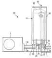
図1は、実施の形態1の貯湯式給湯機を示す図である。図1のように、本実施の形態1の貯湯式給湯機50は、HP(ヒートポンプ)ユニット1と、貯湯タンクユニット40とを備える。貯湯タンクユニット40は、円筒状の形状を有する貯湯タンク10と、直方体状の形状を有する筐体30とを備える。貯湯タンク10は、断熱材に覆われた状態で、筐体30内に収納されている。HPユニット1は、水を加熱して湯を生成する加熱手段の例である。貯湯タンク10に貯留された湯は、必要に応じ所定の給湯先に供給される。加熱手段は、ヒートポンプ式に限定されるものではなく、例えば、貯湯タンク10内にヒータを設置する構成など、いかなる構成でもよい。
Embodiment 1 FIG.
FIG. 1 is a diagram illustrating a hot water storage type hot water supply apparatus according to a first embodiment. As shown in FIG. 1, the hot water storage type water heater 50 according to the first embodiment includes an HP (heat pump) unit 1 and a hot water storage tank unit 40. The hot water storage tank unit 40 includes a hot water storage tank 10 having a cylindrical shape and a housing 30 having a rectangular parallelepiped shape. The hot water storage tank 10 is housed in the housing 30 in a state covered with a heat insulating material. The HP unit 1 is an example of a heating unit that generates hot water by heating water. Hot water stored in the hot water storage tank 10 is supplied to a predetermined hot water supply destination as necessary. The heating means is not limited to the heat pump type, and may be any configuration such as a configuration in which a heater is installed in the hot water storage tank 10.

貯湯タンク10の下部には、給水配管11と、貯湯タンク10内の低温水をHPユニット1に送るためのHP往き配管13aとが接続されている。また、貯湯タンク10の上部には、HPユニット1により加熱された湯を貯湯タンク10内へ戻すためのHP戻り配管13bが接続されている。給湯配管12は、浴室のシャワーあるいは台所の蛇口等の所定の給湯栓(図示せず)に給湯するための配管である。ふろ往き配管14は、浴槽(図示省略)に給湯するための配管である。   Connected to the lower part of the hot water storage tank 10 are a water supply pipe 11 and an HP forward pipe 13 a for sending low temperature water in the hot water storage tank 10 to the HP unit 1. Further, an HP return pipe 13 b for returning hot water heated by the HP unit 1 into the hot water storage tank 10 is connected to the upper part of the hot water storage tank 10. The hot water supply pipe 12 is a pipe for supplying hot water to a predetermined hot water tap (not shown) such as a bathroom shower or a kitchen faucet. The bath piping 14 is a piping for supplying hot water to a bathtub (not shown).

貯湯タンクユニット40の筐体30の上面は、天板32で構成されている。また、筐体30の下部には、前面側が引っ込んだけこみ部31が形成されている。けこみ部31には、上述した給水配管11、HP往き配管13a、HP戻り配管13b、給湯配管12、ふろ往き配管14の各々を貯湯タンクユニット40内に引き込むため、または貯湯タンクユニット40内から引き出すための配管接続部がそれぞれ設けられている。   An upper surface of the housing 30 of the hot water storage tank unit 40 is constituted by a top plate 32. In addition, a recessed portion 31 is formed in the lower portion of the housing 30 so that the front side is retracted. The retracting section 31 is configured to draw each of the water supply pipe 11, the HP forward pipe 13 a, the HP return pipe 13 b, the hot water supply pipe 12, and the bathroom forward pipe 14 into the hot water storage tank unit 40 or from the hot water storage tank unit 40. A pipe connection for drawing out is provided.

筐体30の内部には、湯水が通る配管、ポンプ、バルブ、熱交換器などの各種の機器(図示省略)がさらに配置されてもよい。   Various devices (not shown) such as pipes, pumps, valves, heat exchangers, and the like through which hot water passes may be further arranged inside the housing 30.

筐体30の下部には支持脚35が接続されている。各支持脚35をコンクリート製の土台Cにアンカーボルト(図示省略)で固定することにより、貯湯タンクユニット40が土台Cに据え付けられている。なお、上記の配管接続部および配管接続部に接続された各配管を覆い隠して貯湯タンクユニット40の意匠性を向上させるために、筐体30の下方には配管カバー(図示省略)が設けられる。   Support legs 35 are connected to the lower part of the housing 30. The hot water storage tank unit 40 is installed on the base C by fixing the support legs 35 to the concrete base C with anchor bolts (not shown). In addition, a pipe cover (not shown) is provided below the housing 30 in order to improve the design of the hot water storage tank unit 40 by covering the pipe connection part and each pipe connected to the pipe connection part. .

上述の構成を有する貯湯式給湯機50では、給水配管11からの給水により貯湯タンク10内が上層の高温湯と下層の低温水とで常時満水状態に保たれると共に、貯湯タンク10内の湯水に給水配管11から常時送水圧が付与される。沸上運転時には、貯湯タンク10内の下部にある低温水がHP往き配管13aを通ってHPユニット1内の熱交換器に送られ、熱交換器で沸上げられて高温の湯となる。その湯は、HP戻り配管13bを通って貯湯タンク10に戻り、上部から貯湯タンク10内に流入する。   In the hot water storage type hot water heater 50 having the above-described configuration, the hot water storage tank 10 is always filled with the high temperature hot water in the upper layer and the low temperature water in the lower layer by the water supply from the water supply pipe 11, and the hot water in the hot water storage tank 10 is maintained. A constant water supply pressure is applied to the water supply pipe 11. At the time of boiling operation, the low temperature water in the lower part of the hot water storage tank 10 is sent to the heat exchanger in the HP unit 1 through the HP outgoing pipe 13a, and is boiled by the heat exchanger to become hot hot water. The hot water returns to the hot water storage tank 10 through the HP return pipe 13b and flows into the hot water storage tank 10 from above.

給湯時には、給水配管11からの送水圧により貯湯タンク10内の高温の湯が給湯管路に流入し、その高温の湯と給水配管11からの低温水とが混合弁によって混合されることにより、使用者がリモコン(図示省略)等で設定した給湯温度の湯が生成され、その湯が給湯配管12あるいはふろ往き配管14を通って、浴室、台所等の所定の給湯栓あるいは浴槽に供給される。   At the time of hot water supply, the hot water in the hot water storage tank 10 flows into the hot water supply pipe line by the water supply pressure from the water supply pipe 11, and the hot water and the low temperature water from the water supply pipe 11 are mixed by the mixing valve. Hot water having a hot water temperature set by a user with a remote controller (not shown) or the like is generated, and the hot water is supplied to a predetermined hot water tap or a bathtub in a bathroom, a kitchen, etc. through the hot water supply pipe 12 or the flow-out pipe 14. .

貯湯タンク10の上部には、圧力逃し弁(図示省略)が接続されている。貯湯タンク10内の水をHPユニット1により加熱すると、水が体積膨張することで、貯湯タンク10の内圧が上昇する。圧力逃し弁は、貯湯タンク10の内圧が所定値以上になると開弁する。沸上運転時に、貯湯タンク10の内圧が上昇すると、圧力逃し弁が開弁して、水の体積膨張の分に相当する量の高温水(以下、「膨張水」と称する)が系外に排出されることで、貯湯タンク10の内圧過上昇が防止される。   A pressure relief valve (not shown) is connected to the upper part of the hot water storage tank 10. When the water in the hot water storage tank 10 is heated by the HP unit 1, the internal pressure of the hot water storage tank 10 increases due to the volume expansion of the water. The pressure relief valve opens when the internal pressure of the hot water storage tank 10 exceeds a predetermined value. When the internal pressure of the hot water storage tank 10 rises during boiling operation, the pressure relief valve opens, and an amount of high-temperature water (hereinafter referred to as “expanded water”) corresponding to the volume expansion of water is removed from the system. By discharging, an excessive increase in the internal pressure of the hot water storage tank 10 is prevented.

貯湯タンク10の下部には、排水弁(図示省略)が接続されている。貯湯式給湯機50の使用を休止するとき、あるいは貯湯式給湯機50の修理をするときなどに、貯湯タンク10内の水を抜くことがある。貯湯タンク10内の水を抜く場合に、排水弁を開く操作を行うことで、貯湯タンク10内の水を排水できる。   A drain valve (not shown) is connected to the lower part of the hot water storage tank 10. The water in the hot water storage tank 10 may be drained when the use of the hot water storage type hot water heater 50 is stopped or when the hot water storage type hot water heater 50 is repaired. When the water in the hot water storage tank 10 is drained, the water in the hot water storage tank 10 can be drained by performing an operation of opening the drain valve.

筐体30の底部にドレンパン33が備えられている。万一、貯湯タンクユニット40の内部での漏水、すなわち貯湯タンク10または他の機器からの漏水、が発生した場合に、漏れた水をドレンパン33が受ける。ドレンパン33には、排水部20が取り付けられている。ドレンパン33の上面には、傾斜あるいは溝が形成されている。ドレンパン33が受けた水は、当該傾斜あるいは溝により、ドレンパン33の所定の箇所に集まる。ドレンパン33の水の集まる箇所に排水部20が配置されている。   A drain pan 33 is provided at the bottom of the housing 30. In the unlikely event that water leaks inside the hot water storage tank unit 40, that is, water leaks from the hot water storage tank 10 or other equipment, the drain pan 33 receives the leaked water. The drain pan 20 is attached to the drain pan 33. An inclination or a groove is formed on the upper surface of the drain pan 33. The water received by the drain pan 33 is collected at a predetermined location of the drain pan 33 by the inclination or the groove. The drainage unit 20 is disposed at a location where the water of the drain pan 33 gathers.

排水部20から貯湯タンクユニット40の筐体30の外部へ水が排出される。図示を省略するが、貯湯タンクユニット40の設置場所には、排水部20から排出される水を受ける排水ホッパーと、排水ホッパーから排水溝などへ排水を導く排水経路とが備えられることが望ましい。   Water is discharged from the drainage unit 20 to the outside of the housing 30 of the hot water storage tank unit 40. Although not shown, it is desirable that the installation location of the hot water storage tank unit 40 be provided with a drain hopper that receives water discharged from the drain 20 and a drain passage that guides drainage from the drain hopper to a drain groove or the like.

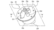
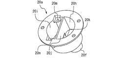
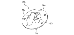
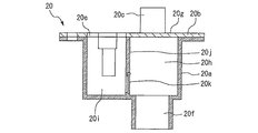
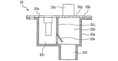
図2は、実施の形態1の貯湯式給湯機50が備える排水部20の斜視図である。図3は、図2に示す排水部20が備えるボディ20aの斜視図である。図4は、図2に示す排水部20が備える蓋部20bの斜視図である。図5及び図6は、図2中のA−A線の位置で切断した断面側面図である。   FIG. 2 is a perspective view of the drainage unit 20 provided in the hot water storage type hot water supply apparatus 50 according to the first embodiment. FIG. 3 is a perspective view of a body 20a included in the drainage unit 20 shown in FIG. FIG. 4 is a perspective view of the lid 20b provided in the drain 20 shown in FIG. 5 and 6 are cross-sectional side views taken along the line AA in FIG.

本実施の形態の排水部20は、図3に示すボディ20aの上面に、図4に示す蓋部20bが取り付けられた構造を有する。図2に示すように、排水部20は、タンク排水流入口20c、逃し弁排水流入口20d、ドレンパン排水流入口20e、及びタンクユニット排水口20fを備える。タンク排水流入口20c、逃し弁排水流入口20d、及びドレンパン排水流入口20eは、蓋部20bに形成されている。タンクユニット排水口20fは、ボディ20aに形成されている。   The drainage unit 20 of the present embodiment has a structure in which a lid 20b shown in FIG. 4 is attached to the upper surface of the body 20a shown in FIG. As shown in FIG. 2, the drainage unit 20 includes a tank drainage inlet 20c, a relief valve drainage inlet 20d, a drain pan drainage inlet 20e, and a tank unit drainage port 20f. The tank drain inlet 20c, the relief valve drain inlet 20d, and the drain pan drain inlet 20e are formed in the lid portion 20b. The tank unit drain port 20f is formed in the body 20a.

タンク排水流入口20cには、前述した排水弁から排出された水を導く排水ホース(図示省略)が接続される。タンク排水流入口20cは、蓋部20bの上面20gより上方へ突出している。タンク排水流入口20cの突出部分に対して当該排水ホースが接続される。排水弁が開かれた場合には、貯湯タンク10内の湯水が、排水弁及び当該排水ホースを通り、タンク排水流入口20cから排水部20内へ流入する。   A drainage hose (not shown) that guides the water discharged from the aforementioned drainage valve is connected to the tank drainage inlet 20c. The tank drainage inlet 20c protrudes upward from the upper surface 20g of the lid 20b. The drain hose is connected to the protruding portion of the tank drain inlet 20c. When the drain valve is opened, hot water in the hot water storage tank 10 passes through the drain valve and the drain hose and flows into the drain section 20 from the tank drain inlet 20c.

逃し弁排水流入口20dには、前述した圧力逃し弁から排出された水を導く排水ホース(図示省略)が接続される。逃し弁排水流入口20dは、蓋部20bの上面20gより上方へ突出している。逃し弁排水流入口20dの突出部分に対して当該排水ホースが接続される。例えば沸上運転時に、圧力逃し弁から排出された膨張水が、圧力逃し弁及び当該排水ホースを通り、逃し弁排水流入口20dから排水部20内へ流入する。   A drainage hose (not shown) that guides the water discharged from the pressure relief valve described above is connected to the relief valve drainage inlet 20d. The relief valve drain inlet 20d protrudes upward from the upper surface 20g of the lid 20b. The drain hose is connected to the protruding portion of the relief valve drain inlet 20d. For example, during boiling operation, the expanded water discharged from the pressure relief valve passes through the pressure relief valve and the drainage hose and flows into the drainage unit 20 from the relief valve drainage inlet 20d.

ドレンパン排水流入口20eは、蓋部20bの上面20gにおいて開口する。ドレンパン排水流入口20eは、貯湯タンクユニット40の筐体30の内部空間に対して開放している。ドレンパン33が受けた水は、ドレンパン33の傾斜あるいは溝により、排水部20の設置箇所に集まり、ドレンパン排水流入口20eから排水部20内へ流入する。   The drain pan drainage inlet 20e opens at the upper surface 20g of the lid 20b. The drain pan drainage inlet 20 e is open to the internal space of the housing 30 of the hot water storage tank unit 40. The water received by the drain pan 33 gathers at the installation location of the drainage part 20 due to the inclination or groove of the drain pan 33 and flows into the drainage part 20 from the drain pan drainage inlet 20e.

図3及び図5に示すように、排水部20は、第一空間20h、第二空間20i、隔壁20j、及び逆止弁20kを備える。タンク排水流入口20c及び逃し弁排水流入口20dを通った水は、第一空間20hに流入する。ドレンパン排水流入口20eを通った水は、第二空間20iに流入する。隔壁20jは、第一空間20hと第二空間20iとの間を隔てる。タンクユニット排水口20fは、第一空間20hの下部にある。第一空間20hは、タンクユニット排水口20fに連通する。   As shown in FIGS. 3 and 5, the drainage unit 20 includes a first space 20h, a second space 20i, a partition wall 20j, and a check valve 20k. The water that has passed through the tank drainage inlet 20c and the relief valve drainage inlet 20d flows into the first space 20h. The water that has passed through the drain pan drainage inlet 20e flows into the second space 20i. The partition wall 20j separates the first space 20h and the second space 20i. The tank unit drain port 20f is in the lower part of the first space 20h. The first space 20h communicates with the tank unit drain 20f.

排水部20において、タンク排水流入口20cから第一空間20hに流入した水は、そのままタンクユニット排水口20fから排水部20外へ排出される。逃し弁排水流入口20dから第一空間20hに流入した水は、そのままタンクユニット排水口20fから排水部20外へ排出される。   In the drainage part 20, the water that flows into the first space 20h from the tank drainage inlet 20c is directly discharged from the tank unit drainage port 20f to the outside of the drainage part 20. The water that has flowed into the first space 20h from the relief valve drain inlet 20d is directly discharged from the tank unit drain port 20f to the outside of the drain section 20.

逆止弁20kは、第二空間20iから第一空間20hへの流体の流れを許容し、第一空間20hから第二空間20iへの流体の流れを阻止する。図5は、逆止弁20kが閉じている状態を示す。図6は、逆止弁20kが開いている状態を示す。   The check valve 20k allows the flow of fluid from the second space 20i to the first space 20h, and blocks the flow of fluid from the first space 20h to the second space 20i. FIG. 5 shows a state where the check valve 20k is closed. FIG. 6 shows a state where the check valve 20k is open.

本実施の形態における逆止弁20kは、スイング式の逆止弁である。図5及び図6に示すように、逆止弁20kは、隔壁20jに形成された通路となる開口を開閉可能な板状の弁体が、上側にあるヒンジを介して隔壁20jに対して回動可能に連結された構造を有する。ドレンパン排水流入口20eから第二空間20iに水が流入すると、その水の圧力によって逆止弁20kが開く。逆止弁20kが開くと、第二空間20iの水が逆止弁20k及び第一空間20hを通ってタンクユニット排水口20fから排水部20外へ排出される。   The check valve 20k in the present embodiment is a swing type check valve. As shown in FIGS. 5 and 6, the check valve 20k is configured such that a plate-like valve body capable of opening and closing an opening serving as a passage formed in the partition wall 20j rotates with respect to the partition wall 20j via an upper hinge. It has a movably connected structure. When water flows into the second space 20i from the drain pan drainage inlet 20e, the check valve 20k is opened by the pressure of the water. When the check valve 20k is opened, the water in the second space 20i passes through the check valve 20k and the first space 20h and is discharged from the tank unit drain port 20f to the outside of the drainage unit 20.

本実施の形態であれば、以下の効果が得られる。排水部20が、タンク排水流入口20c、逃し弁排水流入口20d、ドレンパン排水流入口20e、及びタンクユニット排水口20fを一体的に備えたことで、部品点数を少なくできる。このため、貯湯タンクユニット40からの排水に関する構造部分の低コスト化が図れる。   In the present embodiment, the following effects can be obtained. Since the drainage unit 20 integrally includes the tank drainage inlet 20c, the relief valve drainage inlet 20d, the drain pan drainage inlet 20e, and the tank unit drainage port 20f, the number of parts can be reduced. For this reason, cost reduction of the structure part regarding the waste_water | drain from the hot water storage tank unit 40 can be achieved.

排水弁が開かれた場合には、貯湯タンク10内の湯水がタンク排水流入口20cから排水部20に入り、タンクユニット排水口20fから排出される。その際の排水の流量は、大きい流量になる可能性がある。本実施の形態であれば、タンク排水流入口20cからの水が流入する第一空間20hと、ドレンパン排水流入口20eからの水が流入する第二空間20iとを隔てる隔壁20jを備えたことで、以下の効果が得られる。タンク排水流入口20cから大流量の湯水が第一空間20hに流入しても、第一空間20hから第二空間20iへ湯水が流れることを確実に抑制できる。このため、タンク排水流入口20cから流量した湯水がドレンパン排水流入口20eへ逆流することを確実に抑制できる。すなわち、貯湯タンク10内を排水するときに、ドレンパン排水流入口20eから筐体30の内部空間へ湯水が逆流することを確実に抑制できる。また、貯湯タンク10内の高温の湯がタンク排水流入口20cから流入した場合に、その湯から発生する蒸気がドレンパン排水流入口20eから筐体30の内部空間へ逆流することを確実に抑制できる。筐体30の内部空間への水分の流入を確実に抑制することで、筐体30の内部空間の湿度の増加を抑制でき、各機器の信頼性を向上できる。   When the drain valve is opened, hot water in the hot water storage tank 10 enters the drainage section 20 from the tank drainage inlet 20c and is discharged from the tank unit drainage port 20f. There is a possibility that the flow rate of the waste water at that time becomes a large flow rate. According to this embodiment, the partition 20j is provided to separate the first space 20h into which water from the tank drainage inlet 20c flows and the second space 20i into which water from the drain pan drainage inlet 20e flows. The following effects can be obtained. Even if a large amount of hot water flows into the first space 20h from the tank drainage inlet 20c, the hot water can be reliably suppressed from flowing from the first space 20h to the second space 20i. For this reason, it can suppress reliably that the hot water flowed from the tank waste_water | drain inlet 20c flows back into the drain pan drain_water inlet 20e. That is, when draining the hot water storage tank 10, it is possible to reliably prevent hot water from flowing backward from the drain pan drainage inlet 20 e to the internal space of the housing 30. Moreover, when the hot water in the hot water storage tank 10 flows in from the tank drainage inlet 20c, it is possible to reliably prevent the steam generated from the hot water from flowing back from the drain pan drainage inlet 20e to the internal space of the housing 30. . By reliably suppressing the inflow of moisture into the internal space of the housing 30, an increase in humidity in the internal space of the housing 30 can be suppressed, and the reliability of each device can be improved.

逆止弁20kは、タンク排水流入口20cから流入した水がドレンパン排水流入口20eへ流れることを防止する逆流防止構造の例である。本実施の形態であれば、逆止弁20kを備えたことで、以下の効果が得られる。タンク排水流入口20cから大流量の湯水が第一空間20hに流入しても、第一空間20hから第二空間20iへ湯水が流れることをより確実に抑制できる。このため、タンク排水流入口20cから流量した湯水がドレンパン排水流入口20eへ逆流することをより確実に抑制できる。すなわち、貯湯タンク10内を排水するときに、ドレンパン排水流入口20eから筐体30の内部空間へ水が逆流することをより確実に抑制できる。また、貯湯タンク10内の高温の湯がタンク排水流入口20cから流入した場合に、その湯から発生する蒸気がドレンパン排水流入口20eから筐体30の内部空間へ逆流することをより確実に抑制できる。   The check valve 20k is an example of a backflow prevention structure that prevents water flowing from the tank drainage inlet 20c from flowing to the drain pan drainage inlet 20e. In the present embodiment, the following effects can be obtained by providing the check valve 20k. Even if a large amount of hot water flows into the first space 20h from the tank drainage inlet 20c, it is possible to more reliably suppress the hot water from flowing from the first space 20h to the second space 20i. For this reason, it can suppress more reliably that the hot water flowed from the tank waste_water | drain inlet 20c flows back into the drain pan drain_water inlet 20e. That is, when draining the hot water storage tank 10, it is possible to more reliably prevent water from flowing backward from the drain pan drainage inlet 20 e to the internal space of the housing 30. In addition, when hot water in the hot water storage tank 10 flows in from the tank drain inlet 20c, the steam generated from the hot water is more reliably prevented from flowing back from the drain pan drain inlet 20e to the internal space of the housing 30. it can.

本実施の形態であれば、逆止弁20kがスイング式の逆止弁であることで、さらに以下の効果が得られる。スイング式の逆止弁は、低水頭圧でも開く。このため、ドレンパン排水流入口20eから第二空間20iへ流入した水が少量であっても、より確実に逆止弁20kが開き、その水をタンクユニット排水口20f側へ排出できる。また、スイング式の逆止弁は、構造が簡単で、安価である点においても好ましい。   According to the present embodiment, the check valve 20k is a swing type check valve, and the following effects can be further obtained. Swing check valve opens even at low head pressure. For this reason, even if a small amount of water flows into the second space 20i from the drain pan drainage inlet 20e, the check valve 20k opens more reliably, and the water can be discharged to the tank unit drainage port 20f side. Further, the swing type check valve is preferable in that the structure is simple and the cost is low.

図5及び図6に示すように、本実施の形態では、逆止弁20kは、ドレンパン排水流入口20eからの水が流入する第二空間20iの最下部にある。このため、ドレンパン排水流入口20eから流入した水が第二空間20iに溜まることをより確実に抑制できる。   As shown in FIG.5 and FIG.6, in this Embodiment, the non-return valve 20k exists in the lowest part of the 2nd space 20i into which the water from the drain pan drainage inflow port 20e flows in. For this reason, it can suppress more reliably that the water which flowed in from the drain pan drainage inflow port 20e accumulates in the 2nd space 20i.

逆止弁20kは、無くてもよい。逆止弁20kが無い場合でも、隔壁20jに形成する開口を適度な大きさにすることで、タンク排水流入口20cから大流量の湯水が第一空間20hに流入したときに、第一空間20hから第二空間20iへ湯水が流れることを抑制することが可能である。すなわち、貯湯タンク10内を排水するときに、ドレンパン排水流入口20eから筐体30の内部空間へ湯水が逆流することを抑制することが可能である。また、貯湯タンク10内の高温の湯がタンク排水流入口20cから流入した場合に、その湯から発生する蒸気がドレンパン排水流入口20eから筐体30の内部空間へ逆流することを抑制することが可能である。   The check valve 20k may not be provided. Even when there is no check valve 20k, the opening formed in the partition wall 20j is appropriately sized so that when a large amount of hot water flows into the first space 20h from the tank drainage inlet 20c, the first space 20h It is possible to prevent hot water from flowing from the first to the second space 20i. That is, when draining the hot water storage tank 10, it is possible to prevent hot water from flowing backward from the drain pan drainage inlet 20 e to the internal space of the housing 30. Further, when hot water in the hot water storage tank 10 flows from the tank drainage inlet 20c, it is possible to prevent the steam generated from the hot water from flowing backward from the drain pan drainage inlet 20e to the internal space of the housing 30. Is possible.

本実施の形態であれば、逃し弁排水流入口20dから膨張水が第一空間20hに流入した際にも、上記と同様にして、膨張水、及び膨張水から発生する蒸気が、ドレンパン排水流入口20eから筐体30の内部空間へ逆流することを抑制できる。   In the present embodiment, when the expanded water flows into the first space 20h from the relief valve drain inlet 20d, the expanded water and the steam generated from the expanded water are discharged into the drain pan drain flow in the same manner as described above. Backflow from the inlet 20e to the internal space of the housing 30 can be suppressed.

本発明では、排水部20が逃し弁排水流入口20dを備えなくてもよい。本発明では、圧力逃し弁から排出された水が、排水部20以外の場所から貯湯タンクユニット40外へ排出されてもよい。   In the present invention, the drainage unit 20 may not include the relief valve drainage inlet 20d. In the present invention, the water discharged from the pressure relief valve may be discharged outside the hot water storage tank unit 40 from a place other than the drainage unit 20.

実施の形態2.
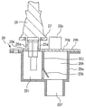
次に、図7を参照して、実施の形態2について説明するが、上述した実施の形態1との相違点を中心に説明し、同一部分または相当部分については説明を簡略化または省略する。図7は、実施の形態2の貯湯式給湯機50が備える排水部20、及び排水部20に取り付けられた漏水センサ25の断面側面図である。実施の形態2の貯湯式給湯機50が備える排水部20自体の構成は、実施の形態1と同様である。
Embodiment 2. FIG.
Next, the second embodiment will be described with reference to FIG. 7. The description will focus on the differences from the first embodiment described above, and the description of the same or corresponding parts will be simplified or omitted. FIG. 7 is a cross-sectional side view of the drainage unit 20 provided in the hot-water storage type hot water heater 50 of the second embodiment and the water leakage sensor 25 attached to the drainage unit 20. The configuration of the drainage section 20 itself provided in the hot water storage type hot water supply apparatus 50 of the second embodiment is the same as that of the first embodiment.

図7に示すように、本実施の形態2の貯湯式給湯機50は、ドレンパン排水流入口20eからの水が流入する第二空間20iに溜まった水を検知する漏水センサ25を備える。漏水センサ25は、ドレンパン排水流入口20eに対向する位置、すなわちドレンパン排水流入口20eの上方の位置に設置されている。漏水センサ25は、一対の電極25aを備える。電極25aの先端すなわち下端は、ドレンパン排水流入口20e内に挿入している。漏水センサ25は、センサ固定部品27を介して、排水部20に対して固定されている。センサ固定部品27は、排水部20のボディ20aに形成されたねじ穴20m(図3参照)に対してねじ止めされている。センサ固定部品27に対して漏水センサ25が固定されている。   As shown in FIG. 7, the hot water storage type water heater 50 of the second embodiment includes a water leakage sensor 25 that detects water accumulated in the second space 20i into which water from the drain pan drainage inlet 20e flows. The water leakage sensor 25 is installed at a position facing the drain pan drain inlet 20e, that is, at a position above the drain pan drain inlet 20e. The water leakage sensor 25 includes a pair of electrodes 25a. The tip, that is, the lower end of the electrode 25a is inserted into the drain pan drainage inlet 20e. The water leakage sensor 25 is fixed to the drainage part 20 via a sensor fixing part 27. The sensor fixing component 27 is screwed to a screw hole 20m (see FIG. 3) formed in the body 20a of the drainage unit 20. The water leakage sensor 25 is fixed to the sensor fixing component 27.

ドレンパン排水流入口20eから流入した水が第二空間20iに溜まり、第二空間20iの水位が上がると、電極25aが水に触れる。電極25aが水に触れると、漏水センサ25が漏水を検知する。貯湯式給湯機50が備える制御装置(図示省略)は、漏水センサ25が漏水を検知した場合には、給水配管11に備えられた給水電磁弁(図示省略)を閉じることで、貯湯タンクユニット40への給水を自動的に停止してもよい。そのようにすることで、漏水の拡大を防止できる。   When the water flowing in from the drain pan drainage inlet 20e accumulates in the second space 20i and the water level of the second space 20i rises, the electrode 25a touches the water. When the electrode 25a touches water, the water leakage sensor 25 detects water leakage. When the water leakage sensor 25 detects water leakage, the control device (not shown) provided in the hot water storage type hot water heater 50 closes the water supply electromagnetic valve (not shown) provided in the water supply pipe 11 to thereby store the hot water storage tank unit 40. The water supply to may be automatically stopped. By doing so, the expansion of water leakage can be prevented.

ドレンパン33で受ける排水には、貯湯タンクユニット40内の貯湯タンク10または他の機器からの漏水のほかに、貯湯タンクユニット40内の気温変化による結露水が自然にドレンパン33に溜まってくる排水、雨水が筐体30の隙間より貯湯タンクユニット40内に侵入した排水などがある。結露水あるいは雨水に起因するドレンパン33から排水部20への排水の流入は、異常ではないので、漏水センサ25で検知すべきではない。結露水あるいは雨水に起因するドレンパン33から排水部20への排水の流量は、例えば0.01L/分程度と小さい。そのような小流量の排水がドレンパン排水流入口20eから第二空間20iに流入した場合には、その水は第二空間20iにほとんど溜まることなく、速やかに逆止弁20kを通過してタンクユニット排水口20fから排出される。この場合には、第二空間20iの水位は上昇せず、電極25aは水に触れず、漏水センサ25は漏水を検知しない。   The drainage received by the drain pan 33 includes drainage in which condensed water due to temperature changes in the hot water storage tank unit 40 naturally accumulates in the drain pan 33 in addition to leakage from the hot water storage tank 10 in the hot water storage tank unit 40 or other devices. There is drainage or the like in which rainwater enters the hot water storage tank unit 40 through a gap between the casings 30. Since the inflow of drainage from the drain pan 33 to the drainage unit 20 due to condensed water or rainwater is not abnormal, it should not be detected by the water leakage sensor 25. The flow rate of drainage from the drain pan 33 to the drainage section 20 due to condensed water or rainwater is as small as, for example, about 0.01 L / min. When such a small flow rate of wastewater flows into the second space 20i from the drain pan drainage inlet 20e, the water hardly accumulates in the second space 20i, and quickly passes through the check valve 20k to the tank unit. It is discharged from the drain port 20f. In this case, the water level of the second space 20i does not rise, the electrode 25a does not touch water, and the water leakage sensor 25 does not detect water leakage.

貯湯タンクユニット40内の貯湯タンク10または他の機器からの漏水が発生した場合には、ドレンパン33から排水部20への排水の流量は、比較的大きい流量、例えば0.3L/分以上になると考えられる。逆止弁20kの口径を適度に設定することで、第二空間20iからタンクユニット排水口20fへ流れる水の流量を制限することが可能である。例えば、ドレンパン排水流入口20eから第二空間20iに流入する排水流量が、所定の漏水閾値(例えば0.3L/分)未満の場合には第二空間20iの水位が上昇せず、当該排水流量が当該漏水閾値を超えると第二空間20iの水位が上昇するように、逆止弁20kの口径を設定することが可能である。すなわち、所定の流量(例えば0.3L/分)以上の排水が流れないように、逆止弁20kの排出量を設定すればよい。   When water leaks from the hot water storage tank 10 or other equipment in the hot water storage tank unit 40, the flow rate of drainage from the drain pan 33 to the drainage unit 20 is relatively large, for example, 0.3 L / min or more. Conceivable. By appropriately setting the diameter of the check valve 20k, the flow rate of water flowing from the second space 20i to the tank unit drain 20f can be limited. For example, when the drainage flow rate flowing into the second space 20i from the drain pan drainage inlet 20e is less than a predetermined water leakage threshold (for example, 0.3 L / min), the water level of the second space 20i does not rise, and the drainage flow rate When the water leakage threshold is exceeded, the diameter of the check valve 20k can be set so that the water level of the second space 20i rises. That is, the discharge amount of the check valve 20k may be set so that drainage at a predetermined flow rate (for example, 0.3 L / min) or more does not flow.

本実施の形態であれば、貯湯タンクユニット40内で漏水閾値を超える流量の漏水が発生すると、第二空間20iの水位が上昇して、漏水センサ25が漏水を検知できる。本実施の形態であれば、結露水あるいは雨水に起因するドレンパン33からの正常な排水を漏水として誤検知することを確実に防止しつつ、貯湯タンクユニット40内での漏水の発生を高精度に検知できる。   In the present embodiment, when a water leak with a flow rate exceeding the water leak threshold value occurs in the hot water storage tank unit 40, the water level in the second space 20i rises and the water leak sensor 25 can detect the water leak. In the present embodiment, the occurrence of water leakage in the hot water storage tank unit 40 can be accurately prevented while reliably preventing normal drainage from the drain pan 33 caused by condensed water or rainwater from being erroneously detected as water leakage. Can be detected.

本実施の形態における逆止弁20kは、第二空間20iからタンクユニット排水口20fへ流れる水の流量を制限する制限手段の例である。   The check valve 20k in the present embodiment is an example of a limiting unit that limits the flow rate of water flowing from the second space 20i to the tank unit drain port 20f.

1 HPユニット、 10 貯湯タンク、 11 給水配管、 12 給湯配管、 13a HP往き配管、 13b HP戻り配管、 14 ふろ往き配管、 20 排水部、 20a ボディ、 20b 蓋部、 20c タンク排水流入口、 20d 逃し弁排水流入口、 20e ドレンパン排水流入口、 20f タンクユニット排水口、 20g 上面、 20h 第一空間、 20i 第二空間、 20j 隔壁、 20k 逆止弁、 20m ねじ穴、 25 漏水センサ、 25a 電極、 27 センサ固定部品、 30 筐体、 31 けこみ部、 32 天板、 33 ドレンパン、 35 支持脚、 40 貯湯タンクユニット、 50 貯湯式給湯機 1 HP unit, 10 hot water storage tank, 11 water supply piping, 12 hot water supply piping, 13a HP forward piping, 13b HP return piping, 14 tapping piping, 20 drainage section, 20a body, 20b lid section, 20c tank drainage inlet, 20d escape Valve drain inlet, 20e drain pan drain inlet, 20f tank unit drain outlet, 20g top surface, 20h first space, 20i second space, 20j bulkhead, 20k check valve, 20m screw hole, 25 water leak sensor, 25a electrode, 27 Sensor fixing parts, 30 housing, 31 indenting part, 32 top plate, 33 drain pan, 35 support legs, 40 hot water storage tank unit, 50 hot water storage type water heater

Claims (7)

貯湯タンクと、
前記貯湯タンクを収納する筐体と、
前記筐体の底部にあるドレンパンと、
排水部と、
を備え、
前記排水部は、前記貯湯タンクから排水される水が流入するタンク排水流入口と、前記ドレンパンが受けた水が流入するドレンパン排水流入口と、前記タンク排水流入口から流入した水と前記ドレンパン排水流入口から流入した水とを前記筐体の外部へ排出するタンクユニット排水口と、を一体的に備える貯湯式給湯機。
A hot water storage tank,
A housing for storing the hot water storage tank;
A drain pan at the bottom of the housing;
A drainage section;
With
The drainage section includes a tank drainage inlet into which water drained from the hot water storage tank flows in, a drain pan drainage inlet into which water received by the drain pan flows, water flowing in from the tank drain inlet, and the drain pan drainage A hot water storage type hot water heater integrally provided with a tank unit drainage port for discharging water flowing in from an inflow port to the outside of the housing.
前記排水部は、前記タンク排水流入口からの水が流入する第一空間と、前記ドレンパン排水流入口からの水が流入する第二空間と、前記第一空間と前記第二空間とを隔てる隔壁とを備える請求項1に記載の貯湯式給湯機。   The drainage portion includes a first space into which water from the tank drainage inlet flows, a second space into which water from the drain pan drainage inlet flows, and a partition that separates the first space and the second space. A hot water storage type water heater according to claim 1. 前記排水部は、前記タンク排水流入口から流入した水が前記ドレンパン排水流入口へ流れることを防止する逆流防止構造を備える請求項1または請求項2に記載の貯湯式給湯機。   The hot water storage hot water supply apparatus according to claim 1 or 2, wherein the drainage unit includes a backflow prevention structure that prevents water flowing from the tank drainage inlet from flowing to the drain pan drainage inlet. 前記逆流防止構造は、前記ドレンパン排水流入口からの水が流入する空間の最下部にある請求項3に記載の貯湯式給湯機。   The hot water storage type water heater according to claim 3, wherein the backflow prevention structure is located at a lowermost part of a space into which water from the drain pan drainage inlet flows. 前記逆流防止構造は、スイング式の逆止弁を備える請求項3または請求項4に記載の貯湯式給湯機。   The hot water storage type water heater according to claim 3 or 4, wherein the backflow prevention structure includes a swing type check valve. 前記ドレンパン排水流入口からの水が流入する空間に溜まった水を検知する漏水センサを備える請求項1から請求項5のいずれか一項に記載の貯湯式給湯機。   The hot water storage type hot water supply apparatus according to any one of claims 1 to 5, further comprising a water leakage sensor that detects water accumulated in a space into which water from the drain pan drainage inlet flows. 前記ドレンパン排水流入口からの水が流入する前記空間から前記タンクユニット排水口へ流れる水の流量を制限する制限手段を備える請求項6に記載の貯湯式給湯機。   The hot water storage type hot water heater according to claim 6, further comprising a restricting unit that restricts a flow rate of water flowing from the space into which water from the drain pan drainage inlet flows into the tank unit drainage port.
JP2016078832A 2016-04-11 2016-04-11 Hot water storage type water heater Expired - Fee Related JP6696275B2 (en)

Priority Applications (1)

Application Number Priority Date Filing Date Title
JP2016078832A JP6696275B2 (en) 2016-04-11 2016-04-11 Hot water storage type water heater

Applications Claiming Priority (1)

Application Number Priority Date Filing Date Title
JP2016078832A JP6696275B2 (en) 2016-04-11 2016-04-11 Hot water storage type water heater

Publications (2)

Publication Number Publication Date
JP2017190882A true JP2017190882A (en) 2017-10-19
JP6696275B2 JP6696275B2 (en) 2020-05-20

Family

ID=60085765

Family Applications (1)

Application Number Title Priority Date Filing Date
JP2016078832A Expired - Fee Related JP6696275B2 (en) 2016-04-11 2016-04-11 Hot water storage type water heater

Country Status (1)

Country Link
JP (1) JP6696275B2 (en)

Citations (2)

* Cited by examiner, † Cited by third party
Publication number Priority date Publication date Assignee Title
US6318403B1 (en) * 2000-07-11 2001-11-20 Sammy G. Fritz Combination manifold and check valve for a water heater
JP2011043272A (en) * 2009-08-20 2011-03-03 Corona Corp Storage water heater

Patent Citations (2)

* Cited by examiner, † Cited by third party
Publication number Priority date Publication date Assignee Title
US6318403B1 (en) * 2000-07-11 2001-11-20 Sammy G. Fritz Combination manifold and check valve for a water heater
JP2011043272A (en) * 2009-08-20 2011-03-03 Corona Corp Storage water heater

Also Published As

Publication number Publication date
JP6696275B2 (en) 2020-05-20

Similar Documents

Publication Publication Date Title
US20120024386A1 (en) System and method for pressure flushing and cleaning water tanks
US8393383B2 (en) Hot water generator
JP4967836B2 (en) bathroom
JP2010002061A (en) Storage type water heater
JP6696275B2 (en) Hot water storage type water heater
US20070186873A1 (en) Pressure control isolation and flood preventative tank for a hot water based heating system
JP5287528B2 (en) Hot water storage water heater
JP6176586B2 (en) Instant hot water system
JP2017227344A (en) Water heater
ES2537882B1 (en) GRAY WATER REUTILIZER MODULAR APPLIANCES
GB2527751A (en) Accumulator system
RU161455U1 (en) TANK - WATER SUPPLY
JP2011226675A (en) Main stop-system electric water heater
JP6529336B2 (en) Valve device and hot water storage type hot water supply device
JP5997649B2 (en) Drainage structure of hot water storage device
KR20230085957A (en) Leakage prevention structure of kitchen head
JP7167650B2 (en) Storage hot water heater
JP2010002087A (en) Storage type hot water supply device, and passage opening/closing device for storage type water heater
JP2008051348A (en) Hot water storage type water heater
DK202200052Y3 (en) Drainage system for outdoor water systems
JP6182732B2 (en) Hot water storage water heater
JP5260364B2 (en) Fire extinguishing equipment
JP4825147B2 (en) Water heater
DK155296B (en) FLOW WATER HEAT HEATED BY DISPOSAL HEATING OR OTHER FLUID UNDER PRESSURE
RU2105247C1 (en) Boiler house

Legal Events

Date Code Title Description
A621 Written request for application examination

Free format text: JAPANESE INTERMEDIATE CODE: A621

Effective date: 20180510

A977 Report on retrieval

Free format text: JAPANESE INTERMEDIATE CODE: A971007

Effective date: 20190118

A131 Notification of reasons for refusal

Free format text: JAPANESE INTERMEDIATE CODE: A131

Effective date: 20190305

A521 Request for written amendment filed

Free format text: JAPANESE INTERMEDIATE CODE: A523

Effective date: 20190422

A131 Notification of reasons for refusal

Free format text: JAPANESE INTERMEDIATE CODE: A131

Effective date: 20190903

A521 Request for written amendment filed

Free format text: JAPANESE INTERMEDIATE CODE: A523

Effective date: 20191029

TRDD Decision of grant or rejection written
A01 Written decision to grant a patent or to grant a registration (utility model)

Free format text: JAPANESE INTERMEDIATE CODE: A01

Effective date: 20200324

A61 First payment of annual fees (during grant procedure)

Free format text: JAPANESE INTERMEDIATE CODE: A61

Effective date: 20200406

R150 Certificate of patent or registration of utility model

Ref document number: 6696275

Country of ref document: JP

Free format text: JAPANESE INTERMEDIATE CODE: R150

LAPS Cancellation because of no payment of annual fees